EP2420780A2 - Unité de stockage pour produit surgelé dotée d'un support de produit surgelé - Google Patents
Unité de stockage pour produit surgelé dotée d'un support de produit surgelé Download PDFInfo
- Publication number
- EP2420780A2 EP2420780A2 EP11172654A EP11172654A EP2420780A2 EP 2420780 A2 EP2420780 A2 EP 2420780A2 EP 11172654 A EP11172654 A EP 11172654A EP 11172654 A EP11172654 A EP 11172654A EP 2420780 A2 EP2420780 A2 EP 2420780A2
- Authority
- EP
- European Patent Office
- Prior art keywords
- refrigerated goods
- support frame
- unit according
- bearing unit
- goods carrier
- Prior art date
- Legal status (The legal status is an assumption and is not a legal conclusion. Google has not performed a legal analysis and makes no representation as to the accuracy of the status listed.)
- Granted
Links
- 230000001419 dependent effect Effects 0.000 claims 1
- 238000001816 cooling Methods 0.000 abstract description 4
- 238000005057 refrigeration Methods 0.000 description 6
- 239000000969 carrier Substances 0.000 description 3
- 239000003507 refrigerant Substances 0.000 description 3
- 238000004873 anchoring Methods 0.000 description 1
- 238000005452 bending Methods 0.000 description 1
- 235000013361 beverage Nutrition 0.000 description 1
- 238000004519 manufacturing process Methods 0.000 description 1
- 230000004048 modification Effects 0.000 description 1
- 238000012986 modification Methods 0.000 description 1
Images


Classifications
-
- F—MECHANICAL ENGINEERING; LIGHTING; HEATING; WEAPONS; BLASTING
- F25—REFRIGERATION OR COOLING; COMBINED HEATING AND REFRIGERATION SYSTEMS; HEAT PUMP SYSTEMS; MANUFACTURE OR STORAGE OF ICE; LIQUEFACTION SOLIDIFICATION OF GASES
- F25D—REFRIGERATORS; COLD ROOMS; ICE-BOXES; COOLING OR FREEZING APPARATUS NOT OTHERWISE PROVIDED FOR
- F25D25/00—Charging, supporting, and discharging the articles to be cooled
- F25D25/02—Charging, supporting, and discharging the articles to be cooled by shelves
- F25D25/024—Slidable shelves
- F25D25/025—Drawers
-
- F—MECHANICAL ENGINEERING; LIGHTING; HEATING; WEAPONS; BLASTING
- F25—REFRIGERATION OR COOLING; COMBINED HEATING AND REFRIGERATION SYSTEMS; HEAT PUMP SYSTEMS; MANUFACTURE OR STORAGE OF ICE; LIQUEFACTION SOLIDIFICATION OF GASES
- F25D—REFRIGERATORS; COLD ROOMS; ICE-BOXES; COOLING OR FREEZING APPARATUS NOT OTHERWISE PROVIDED FOR
- F25D25/00—Charging, supporting, and discharging the articles to be cooled
- F25D25/02—Charging, supporting, and discharging the articles to be cooled by shelves
-
- A—HUMAN NECESSITIES
- A47—FURNITURE; DOMESTIC ARTICLES OR APPLIANCES; COFFEE MILLS; SPICE MILLS; SUCTION CLEANERS IN GENERAL
- A47B—TABLES; DESKS; OFFICE FURNITURE; CABINETS; DRAWERS; GENERAL DETAILS OF FURNITURE
- A47B88/00—Drawers for tables, cabinets or like furniture; Guides for drawers
- A47B88/40—Sliding drawers; Slides or guides therefor
- A47B88/417—Profiled cabinet walls with grooves or protuberances for supporting drawers
-
- A—HUMAN NECESSITIES
- A47—FURNITURE; DOMESTIC ARTICLES OR APPLIANCES; COFFEE MILLS; SPICE MILLS; SUCTION CLEANERS IN GENERAL
- A47B—TABLES; DESKS; OFFICE FURNITURE; CABINETS; DRAWERS; GENERAL DETAILS OF FURNITURE
- A47B95/00—Fittings for furniture
- A47B95/02—Handles
-
- F—MECHANICAL ENGINEERING; LIGHTING; HEATING; WEAPONS; BLASTING
- F25—REFRIGERATION OR COOLING; COMBINED HEATING AND REFRIGERATION SYSTEMS; HEAT PUMP SYSTEMS; MANUFACTURE OR STORAGE OF ICE; LIQUEFACTION SOLIDIFICATION OF GASES
- F25D—REFRIGERATORS; COLD ROOMS; ICE-BOXES; COOLING OR FREEZING APPARATUS NOT OTHERWISE PROVIDED FOR
- F25D23/00—General constructional features
- F25D23/06—Walls
- F25D23/065—Details
- F25D23/067—Supporting elements
-
- F—MECHANICAL ENGINEERING; LIGHTING; HEATING; WEAPONS; BLASTING
- F25—REFRIGERATION OR COOLING; COMBINED HEATING AND REFRIGERATION SYSTEMS; HEAT PUMP SYSTEMS; MANUFACTURE OR STORAGE OF ICE; LIQUEFACTION SOLIDIFICATION OF GASES
- F25D—REFRIGERATORS; COLD ROOMS; ICE-BOXES; COOLING OR FREEZING APPARATUS NOT OTHERWISE PROVIDED FOR
- F25D2400/00—General features of, or devices for refrigerators, cold rooms, ice-boxes, or for cooling or freezing apparatus not covered by any other subclass
- F25D2400/16—Convertible refrigerators
Definitions
- the present invention relates to a storage unit for the refrigerated storage of refrigerated goods, in particular food in the household, with a storage chamber and at least one fixable in a support frame, a base plate having refrigerated goods.
- the support frame may be formed by an inner container of the housing of such a storage unit, and asdeguta act in horizontal grooves of the inner container retractable plates.
- these plates are usually removable from the storage unit to adapt their position therein to the particular needs of a user, but their handling is cumbersome, especially if they are loaded with refrigerated goods.
- Out DE 25 45 667 A1 is a storage unit for refrigerated goods is known in which the walls of a storage chamber form a support frame for a refrigerated goods.
- the refrigerated goods carrier is designed as a wire basket with adjustable handles, wherein in an inserted position of the handles of refrigerated goods from above into the refrigerated goods chamber can be inserted and in an extended position of the handles these support the refrigerated goods at an upper edge of the support frame.
- Such a storage unit is cumbersome to use, since to access one of the lower refrigerated goods all overhead must be removed.
- the object of the present invention is to provide a storage unit in which refrigerated goods carriers are both conveniently selectively removable and safe to handle.
- the object is achieved in which in a storage unit for the refrigerated storage of refrigerated goods with a storage chamber and at least one fixable in a support rack refrigerated goods, which has at least one adjustable handle element, wherein in a first position of the handle element this as a handle for handling the refrigerated goods used is and the refrigerated goods from the support frame can be removed, the direction of removal of the refrigerated goods carrier is horizontal and the handle member is movable to a second position in which it fixes the refrigerated goods in a form-fitting manner in the support frame.
- the Horizontal removal allows easy handling of each refrigerated goods carrier, even if several of these are mounted one above the other in the storage unit or mountable.
- the handle member allows in the first position, a secure handling of the refrigerated goods in the removed state and ensures in the second position for a secure anchoring in the support frame.
- a refrigerator according to the invention has one or more such storage units.
- a refrigeration appliance is understood in particular to be a household refrigeration appliance, that is to say a refrigeration appliance used for household purposes or possibly even in the gastronomy sector, and in particular for storing food and / or beverages in household quantities at specific temperatures, such as, for example, a refrigerator, a freezer , a fridge freezer or a wine storage cabinet.
- a horizontal support contour supporting the refrigerated goods carrier is preferably formed, on which the refrigerated goods carrier is displaceable for removal when the gripping element is in the first position.
- the support frame can also be identical to an inner container of the storage unit here.
- An identical not with the inner container support frame is easily and stably realized by means of two connected by the support contour columns.
- this may have a stop for the refrigerated goods, which is arranged so that the handle member is movable from the first to the second position when the refrigerated goods is located at the stop.
- the gripping element and the support frame can be provided with two pairs of transverse to the direction of movement of the refrigerated goods carrier oriented stop surfaces, which cooperate in the second position of the handle member to fix the refrigerated goods.
- the support surfaces belonging to the stop surfaces are preferably provided on mutually facing edges of the two columns. This facilitates the one-piece production of the columns and stop surfaces, for example by bending of sheets.
- the storage unit can be erected in two different orientations, a first orientation in which the support contour is horizontal as mentioned above to support the refrigerated goods carrier, and a second orientation in which the stop surfaces are able to support the refrigerated goods.
- the handle member is pivotable about a horizontal axis between the first and second positions, and a first-level downwardly facing surface of the handle member which provides good grip to a user's fingers faces the support frame in the second position.
- a user who wants to remove the refrigerated goods purely intuitively pivot the handle element so that the downwardly facing surface provides good support, and in this way release the lock of the refrigerated goods carrier on the support frame.
- the gripping element has a base plate and two legs bent away from the base plate, which form the stop surfaces of the gripping element, and the stop surfaces of the carrier frame define an opening of the carrier frame lying opposite the base plate.
- the refrigerated goods can be formed box-shaped with the base plate surrounding walls;
- the grip element is expediently arranged on an opening of one of the walls, which engages in the second position in order to lock the refrigerated goods carrier on the carrier frame.
- the base plate of the handle element is preferably offset in the second position with respect to the wall inside thedegutas into, so that the base plate and the wall form a downwardly open, easily accessible to the fingers of the user gap.
- the refrigerated goods can also be formed plate-shaped;
- the grip element is expediently arranged on an underside of the plate.
- the support frame can be pulled out of the storage chamber.
- its lateral flanks are exposed.
- it is therefore most convenient if it can be removed from the extracted support frame transversely to its direction of movement.
- the support frame may be attached to a door of the storage unit or the refrigeration device, so that it can be pulled together with the door or pushed back into the storage chamber.
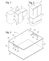
- Fig. 1 shows a schematic perspective view of a modular household refrigerator with a refrigerator unit 1 and two storage units 2, 3.
- the number of connectable to the refrigerator unit 1 and supplied by this with refrigerant storage units is variable, so that a user adjust the number of storage units set up his needs can.
- the dimensions of chillers and storage units are identical. In the case of the two units 1, 2 shown in an upright position, the height is twice the width in each case. A horizontal storage unit could therefore be stacked on the units 1, 2 so that the three units form a cuboid.
- the units 1, 2, 3 are interconnected only by flexible refrigerant lines and electrical lines for control signals. Therefore, there is a great freedom in the arrangement of the individual units, and also irregularly shaped groups, as in Fig. 1 shown to be created.
- Fig. 2 shows an arrangement of modules or units that resembles in their cuboid outer shape of a conventional combination refrigerator.
- the refrigerator unit 1 is here designed for horizontal arrangement, and the ratio of its edge lengths H, B, T is ax2x1, where a is an arbitrary value ⁇ 1, which is essentially only due to the space requirements of the components in the refrigeration unit, such as a compressor, a condenser, a fan for cooling the compressor and condenser and solenoid valves for distributing the refrigerant to the connected storage units 2, 3, is dictated.
- the structure of the upright and the lying storage units 2, 3 is substantially the same.
- the storage units 2, 3 each comprise a body 6 with an open front, a door 4 which covers the open front of the body 6 in the closed position and limits together with this a storage chamber, and a support frame 5, the door 4 attached and pulled out by advancing the door 4 from the storage chamber.
- the support frame 5 comprises a ceiling plate 11, a bottom plate 12, a rear plate 13 connecting the rear edges of the top and bottom plates 11, 12, and a front edge connecting the top and bottom plates 11, 12 Fig. 1 from the door 4 concealed and fixed to the door 4 front panel.
- the lateral flanks of the support frame 5 are open to a comfortable access to held in the support frame 5, in pulled-out position Fig. 1 not shown refrigerated goods and to allow their contents.
- a lying arranged storage unit such as 3
- all four of the support frame 5 forming plates are oriented vertically. By placing a horizontal bottom plate between the plates of the support frame 5, a drawer-like box is obtained, which allows easy access from above to refrigerated goods stored therein.
- refrigerated goods carriers which are used in the storage units 2, 3. It is understood that such refrigerated goods are also in other types of storage unit, especially those in which the body also contains the chiller, are used.
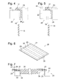
- Fig. 3 is a perspective view of a refrigerated goods carrier 14 according to a first embodiment of the invention.
- the refrigerated goods carrier 14 has essentially the shape of a cuboid, open-topped box. Side walls 15, 16 of the box are stiffened at their upper and lower edges by outwardly angled, forming a continuous frame webs 17, 18. The narrower side walls 15 are adjacent to the upper web 17, each with a handle opening 19 is provided.
- Handle members 20 are pivotally mounted on the handle opening 19 about an adjacent to the upper edge of the handle opening 19 extending horizontal axis.
- the grip elements 20 are pivotable about 90 degrees between two stop positions.
- a base plate 21 of the handle member 20 is oriented substantially horizontally and forms together with the Bottom of the adjacent web 17 has a wide, downwardly facing surface on which a user can engage to lift the box 14.
- the base plate 21 is flanked on two sides by rectangular angled legs 22. In the second position of the handle member 20, shown on the side wall 15 facing the viewer Fig. 3 , these legs 22 protrude through the handle opening 19 and project beyond the web 17 outwards.
- Fig. 4 shows an enlarged section through the upper region of one of the side walls 15 and the handle opening 19 with the handle element 20 hinged thereto.
- a pivot axis of the grip element 20 that is perpendicular to the sectional plane is denoted by 23.
- the second position of the grip element 20 is shown by solid lines, the first dashed lines.
- the base plate 21 of the handle member 20 extends in the second position substantially parallel to the side wall 15, but is offset against this by a few millimeters into the interior of the box 14, so that the side wall 15 and the handle member 20 form a downwardly open gap 24, in a user can insert his fingers from the bottom to grasp the handle member 20 and pivot to the first position.
- Fig. 5 shows a modification of the handle member 20 in one Fig. 4 analogue cut.
- the legs 22 are here each provided with an integrally formed hook 25 which protrudes with respect to the direction of the pivot axis 23 beyond the edges of the handle opening 19, so that its tip comes to lie in the first position shown in dashed lines on an outer side of the side wall 15.
- the hook 25 improves the torque load capacity of the grip element 20, so that the refrigerated goods carrier 14 can be safely lifted even when heavily laden.
- Fig. 6 shows a second embodiment of a refrigerated goods carrier, denoted by 26, in a perspective view.
- the refrigerated goods carrier 26 is formed as a plate or grate, with a circumferential square frame 27 and inserted into the frame 27 strips 28.
- the strips 28 in longitudinal section are substantially trapezoidal, wherein at opposite ends of the trapezoid each have a groove 29 is formed, in which a profile of the frame 27 engages.
- handle members 20 are articulated, which, as with reference to Fig. 3 to 5 described, one each Base plate 21 and from this projecting leg 22 have. Of the two handle elements 20 is in 6 and 7 respectively the left in the first position and the right shown in the second position.
- a central part of the base plate 21 is in the first position, as in Fig. 6 shown between two middle strips 28 free, while the ends of the base plate 21 and the legs 22 each, as in Fig. 7 to see in downwardly open recesses 30 engage the ends of the strips 28 and are supported on the underside of these recesses 30.
- Fig. 8 shows the refrigerated goods 14 Fig. 3
- Back plate 13 and front panel 32 are mirror images of each other.
- a plurality of stacked rectangular or square cutouts 33 divide the plates 13, 31 respectively into right and left pillars 34, which are integrally connected by C-shaped cross sections 35 extending horizontally between the cutouts 33.
- Each section 33 is bordered by a frame consisting of an upper and a lower leg 36, 37 different profiles 35 and the legs 36, 37 interconnecting vertical legs 38 exists.
- the height of the C-profiles 35 is sufficient to receive in each case a lower web 18 of the box-shaped refrigerated goods carrier 14 or the frame 27 of the plate-shaped refrigerated goods carrier 26.
- the height of the box-shaped refrigerated goods carrier 14 is adapted to the shape of the plates 13, 32 so that the upper web 17 of a refrigerated goods carrier 14 mounted in the support frame 5 runs just below a lower horizontal leg 37.
- the plates 13, 32 each have an in Fig. 8 From the viewer facing away from the vertical vertical edge an angled stop leg 39, which defines the depth to which the refrigerated goods 14 can be inserted into the support frame 5 of the observer facing the open side.
- Fig. 9 shows a horizontal section through one of the side walls 15 of the fixed in the set by the stop leg 39 stop position in the support frame 5degutologis 14.
- the protruding through the handle opening 19 from themégutlini 14 legs 22 of the handle member 20 are each at a small distance vertical legs 38 a Section 33 of the back plate 13 opposite.
- the legs 22 could also engage in each case with a small distance from the vertical legs 38 in the cutout 33 to achieve an equivalent locking.
- the storage units are in an upright orientation, as in the description of FIGS. 8 and 9 assumed, and a horizontal orientation can be used, in which all the plates 11, 12, 13, 32 of the support frame 5 are vertically oriented.
- Fig. 10 shows a partial section through the support frame 5 and two refrigerated goods mounted therein in a horizontal orientation of the support frame 5.
- each stop the legs 39 of the plates 13, 32 a support surface on which the lower of the two refrigerated goods 14 rests.
- the legs 22 of the handle member 20th each encompass the outer sides of the upright horizontal legs 36, 37, while one of the upright vertical leg 38 now supports the upper refrigerated goods 14.
- a latching of the upper refrigerated goods carrier 14 by pivoting its gripping elements 20 is not possible here, but also not required, since the each with only short interruptions successive legs 38 of the various cutouts 33 form a nearly continuous support surface from which the upper refrigerated goods 14 fall down can.
Landscapes
- Engineering & Computer Science (AREA)
- Chemical & Material Sciences (AREA)
- Combustion & Propulsion (AREA)
- Physics & Mathematics (AREA)
- Mechanical Engineering (AREA)
- Thermal Sciences (AREA)
- General Engineering & Computer Science (AREA)
- Devices That Are Associated With Refrigeration Equipment (AREA)
Applications Claiming Priority (1)
| Application Number | Priority Date | Filing Date | Title |
|---|---|---|---|
| DE102010031550A DE102010031550A1 (de) | 2010-07-20 | 2010-07-20 | Lagerungseinheit für Kühlgut mit einem Kühlgutträger |
Publications (3)
| Publication Number | Publication Date |
|---|---|
| EP2420780A2 true EP2420780A2 (fr) | 2012-02-22 |
| EP2420780A3 EP2420780A3 (fr) | 2014-11-19 |
| EP2420780B1 EP2420780B1 (fr) | 2017-11-29 |
Family
ID=45437415
Family Applications (1)
| Application Number | Title | Priority Date | Filing Date |
|---|---|---|---|
| EP11172654.3A Active EP2420780B1 (fr) | 2010-07-20 | 2011-07-05 | Unité de stockage pour produit surgelé dotée d'un support de produit surgelé |
Country Status (2)
| Country | Link |
|---|---|
| EP (1) | EP2420780B1 (fr) |
| DE (1) | DE102010031550A1 (fr) |
Families Citing this family (1)
| Publication number | Priority date | Publication date | Assignee | Title |
|---|---|---|---|---|
| DE102017001301A1 (de) * | 2016-11-10 | 2018-05-17 | Liebherr-Hausgeräte Lienz Gmbh | Kühl- und/oder Gefriergerät |
Citations (1)
| Publication number | Priority date | Publication date | Assignee | Title |
|---|---|---|---|---|
| DE2545667A1 (de) | 1974-10-18 | 1976-04-29 | Rene Etienne Jacquet | Korb fuer kuehlkammern |
Family Cites Families (3)
| Publication number | Priority date | Publication date | Assignee | Title |
|---|---|---|---|---|
| ATE390610T1 (de) * | 2003-12-10 | 2008-04-15 | Electrolux Home Prod Corp | Kühl- oder gefriervorrichtung mit vakuumkammer |
| KR100906878B1 (ko) * | 2007-11-05 | 2009-07-08 | 엘지전자 주식회사 | 냉장고의 저장용기 |
| US8267493B2 (en) * | 2009-01-15 | 2012-09-18 | Lg Electronics Inc. | Refrigerator |
-
2010
- 2010-07-20 DE DE102010031550A patent/DE102010031550A1/de not_active Withdrawn
-
2011
- 2011-07-05 EP EP11172654.3A patent/EP2420780B1/fr active Active
Patent Citations (1)
| Publication number | Priority date | Publication date | Assignee | Title |
|---|---|---|---|---|
| DE2545667A1 (de) | 1974-10-18 | 1976-04-29 | Rene Etienne Jacquet | Korb fuer kuehlkammern |
Also Published As
| Publication number | Publication date |
|---|---|
| EP2420780B1 (fr) | 2017-11-29 |
| DE102010031550A1 (de) | 2012-01-26 |
| EP2420780A3 (fr) | 2014-11-19 |
Similar Documents
| Publication | Publication Date | Title |
|---|---|---|
| EP2414756B1 (fr) | Appareil frigorifique ménager | |
| DE102007005951A1 (de) | Butterfach für ein Kältegerät | |
| EP1831626B1 (fr) | Appareil frigorifique | |
| EP1728036B1 (fr) | Support de bouteille pour appareil frigorifique | |
| DE102010001455A1 (de) | Trennelement für ein Haushaltskältegerät | |
| DE102008055038A1 (de) | Kältegerät mit mindestens einer Kühlgutablage sowie Kühlgutablage | |
| WO2007033962A1 (fr) | Appareil de refrigeration dote d'une tablette divisee | |
| WO2011138114A1 (fr) | Système de rangement pour un appareil réfrigérant comportant au moins un plateau de rangement pouvant pivoter horizontalement | |
| DE102016006219A1 (de) | Eierablage | |
| EP2913610A1 (fr) | Réfrigérateur domestique avec tablette et doté d'un dispositif de fixation monté sur la tablette | |
| EP2420780B1 (fr) | Unité de stockage pour produit surgelé dotée d'un support de produit surgelé | |
| WO2008122515A2 (fr) | Élément de rangement de produit à refroidir et réfrigérateur équipé de cet élément | |
| EP3136027B1 (fr) | Appareil ménager frigorifique avec une paroi frontale pour un compartiment de stockage | |
| EP0043540A2 (fr) | Coffret à tiroirs cloisonnés pour assortiment | |
| WO2011160973A1 (fr) | Appareil frigorifique notamment appareil frigorifique ménager | |
| EP3081885B1 (fr) | Appareil frigorifique menager avec une étagère | |
| EP0648990B1 (fr) | Réfrigérateur | |
| DE102009028418A1 (de) | Kältegerät | |
| EP2691717A2 (fr) | Appareil frigorifique | |
| DE102009046027A1 (de) | Kältegerät und Kühlgutträger mit unterteilter Abstellplatte | |
| EP2549211B1 (fr) | Appareil de refroidissement doté d'un support de produit froid pivotant | |
| EP0611932A1 (fr) | Récipient en forme de tiroir | |
| DE102015203835B4 (de) | Haushaltskältegerät mit einem spezifischen Auszugswagen | |
| EP3372930A1 (fr) | Bac à denrées réfrigérées | |
| EP2813790A2 (fr) | Appareil de réfrigération et/ou de congélation |
Legal Events
| Date | Code | Title | Description |
|---|---|---|---|
| AK | Designated contracting states |
Kind code of ref document: A2 Designated state(s): AL AT BE BG CH CY CZ DE DK EE ES FI FR GB GR HR HU IE IS IT LI LT LU LV MC MK MT NL NO PL PT RO RS SE SI SK SM TR |
|
| AX | Request for extension of the european patent |
Extension state: BA ME |
|
| PUAI | Public reference made under article 153(3) epc to a published international application that has entered the european phase |
Free format text: ORIGINAL CODE: 0009012 |
|
| PUAL | Search report despatched |
Free format text: ORIGINAL CODE: 0009013 |
|
| AK | Designated contracting states |
Kind code of ref document: A3 Designated state(s): AL AT BE BG CH CY CZ DE DK EE ES FI FR GB GR HR HU IE IS IT LI LT LU LV MC MK MT NL NO PL PT RO RS SE SI SK SM TR |
|
| AX | Request for extension of the european patent |
Extension state: BA ME |
|
| RIC1 | Information provided on ipc code assigned before grant |
Ipc: F25D 25/02 20060101AFI20141014BHEP |
|
| RAP1 | Party data changed (applicant data changed or rights of an application transferred) |
Owner name: BSH HAUSGERAETE GMBH |
|
| 17P | Request for examination filed |
Effective date: 20150519 |
|
| RBV | Designated contracting states (corrected) |
Designated state(s): AL AT BE BG CH CY CZ DE DK EE ES FI FR GB GR HR HU IE IS IT LI LT LU LV MC MK MT NL NO PL PT RO RS SE SI SK SM TR |
|
| GRAP | Despatch of communication of intention to grant a patent |
Free format text: ORIGINAL CODE: EPIDOSNIGR1 |
|
| INTG | Intention to grant announced |
Effective date: 20170719 |
|
| GRAS | Grant fee paid |
Free format text: ORIGINAL CODE: EPIDOSNIGR3 |
|
| GRAA | (expected) grant |
Free format text: ORIGINAL CODE: 0009210 |
|
| AK | Designated contracting states |
Kind code of ref document: B1 Designated state(s): AL AT BE BG CH CY CZ DE DK EE ES FI FR GB GR HR HU IE IS IT LI LT LU LV MC MK MT NL NO PL PT RO RS SE SI SK SM TR |
|
| REG | Reference to a national code |
Ref country code: CH Ref legal event code: EP |
|
| REG | Reference to a national code |
Ref country code: AT Ref legal event code: REF Ref document number: 950767 Country of ref document: AT Kind code of ref document: T Effective date: 20171215 |
|
| REG | Reference to a national code |
Ref country code: IE Ref legal event code: FG4D Free format text: LANGUAGE OF EP DOCUMENT: GERMAN |
|
| REG | Reference to a national code |
Ref country code: DE Ref legal event code: R096 Ref document number: 502011013351 Country of ref document: DE |
|
| REG | Reference to a national code |
Ref country code: NL Ref legal event code: MP Effective date: 20171129 |
|
| REG | Reference to a national code |
Ref country code: LT Ref legal event code: MG4D |
|
| PG25 | Lapsed in a contracting state [announced via postgrant information from national office to epo] |
Ref country code: FI Free format text: LAPSE BECAUSE OF FAILURE TO SUBMIT A TRANSLATION OF THE DESCRIPTION OR TO PAY THE FEE WITHIN THE PRESCRIBED TIME-LIMIT Effective date: 20171129 Ref country code: NO Free format text: LAPSE BECAUSE OF FAILURE TO SUBMIT A TRANSLATION OF THE DESCRIPTION OR TO PAY THE FEE WITHIN THE PRESCRIBED TIME-LIMIT Effective date: 20180228 Ref country code: LT Free format text: LAPSE BECAUSE OF FAILURE TO SUBMIT A TRANSLATION OF THE DESCRIPTION OR TO PAY THE FEE WITHIN THE PRESCRIBED TIME-LIMIT Effective date: 20171129 Ref country code: SE Free format text: LAPSE BECAUSE OF FAILURE TO SUBMIT A TRANSLATION OF THE DESCRIPTION OR TO PAY THE FEE WITHIN THE PRESCRIBED TIME-LIMIT Effective date: 20171129 Ref country code: ES Free format text: LAPSE BECAUSE OF FAILURE TO SUBMIT A TRANSLATION OF THE DESCRIPTION OR TO PAY THE FEE WITHIN THE PRESCRIBED TIME-LIMIT Effective date: 20171129 |
|
| PG25 | Lapsed in a contracting state [announced via postgrant information from national office to epo] |
Ref country code: HR Free format text: LAPSE BECAUSE OF FAILURE TO SUBMIT A TRANSLATION OF THE DESCRIPTION OR TO PAY THE FEE WITHIN THE PRESCRIBED TIME-LIMIT Effective date: 20171129 Ref country code: GR Free format text: LAPSE BECAUSE OF FAILURE TO SUBMIT A TRANSLATION OF THE DESCRIPTION OR TO PAY THE FEE WITHIN THE PRESCRIBED TIME-LIMIT Effective date: 20180301 Ref country code: LV Free format text: LAPSE BECAUSE OF FAILURE TO SUBMIT A TRANSLATION OF THE DESCRIPTION OR TO PAY THE FEE WITHIN THE PRESCRIBED TIME-LIMIT Effective date: 20171129 Ref country code: RS Free format text: LAPSE BECAUSE OF FAILURE TO SUBMIT A TRANSLATION OF THE DESCRIPTION OR TO PAY THE FEE WITHIN THE PRESCRIBED TIME-LIMIT Effective date: 20171129 Ref country code: BG Free format text: LAPSE BECAUSE OF FAILURE TO SUBMIT A TRANSLATION OF THE DESCRIPTION OR TO PAY THE FEE WITHIN THE PRESCRIBED TIME-LIMIT Effective date: 20180228 |
|
| PG25 | Lapsed in a contracting state [announced via postgrant information from national office to epo] |
Ref country code: NL Free format text: LAPSE BECAUSE OF FAILURE TO SUBMIT A TRANSLATION OF THE DESCRIPTION OR TO PAY THE FEE WITHIN THE PRESCRIBED TIME-LIMIT Effective date: 20171129 |
|
| PG25 | Lapsed in a contracting state [announced via postgrant information from national office to epo] |
Ref country code: CZ Free format text: LAPSE BECAUSE OF FAILURE TO SUBMIT A TRANSLATION OF THE DESCRIPTION OR TO PAY THE FEE WITHIN THE PRESCRIBED TIME-LIMIT Effective date: 20171129 Ref country code: CY Free format text: LAPSE BECAUSE OF FAILURE TO SUBMIT A TRANSLATION OF THE DESCRIPTION OR TO PAY THE FEE WITHIN THE PRESCRIBED TIME-LIMIT Effective date: 20171129 Ref country code: EE Free format text: LAPSE BECAUSE OF FAILURE TO SUBMIT A TRANSLATION OF THE DESCRIPTION OR TO PAY THE FEE WITHIN THE PRESCRIBED TIME-LIMIT Effective date: 20171129 Ref country code: DK Free format text: LAPSE BECAUSE OF FAILURE TO SUBMIT A TRANSLATION OF THE DESCRIPTION OR TO PAY THE FEE WITHIN THE PRESCRIBED TIME-LIMIT Effective date: 20171129 Ref country code: SK Free format text: LAPSE BECAUSE OF FAILURE TO SUBMIT A TRANSLATION OF THE DESCRIPTION OR TO PAY THE FEE WITHIN THE PRESCRIBED TIME-LIMIT Effective date: 20171129 |
|
| REG | Reference to a national code |
Ref country code: DE Ref legal event code: R097 Ref document number: 502011013351 Country of ref document: DE |
|
| PG25 | Lapsed in a contracting state [announced via postgrant information from national office to epo] |
Ref country code: IT Free format text: LAPSE BECAUSE OF FAILURE TO SUBMIT A TRANSLATION OF THE DESCRIPTION OR TO PAY THE FEE WITHIN THE PRESCRIBED TIME-LIMIT Effective date: 20171129 Ref country code: RO Free format text: LAPSE BECAUSE OF FAILURE TO SUBMIT A TRANSLATION OF THE DESCRIPTION OR TO PAY THE FEE WITHIN THE PRESCRIBED TIME-LIMIT Effective date: 20171129 Ref country code: SM Free format text: LAPSE BECAUSE OF FAILURE TO SUBMIT A TRANSLATION OF THE DESCRIPTION OR TO PAY THE FEE WITHIN THE PRESCRIBED TIME-LIMIT Effective date: 20171129 Ref country code: PL Free format text: LAPSE BECAUSE OF FAILURE TO SUBMIT A TRANSLATION OF THE DESCRIPTION OR TO PAY THE FEE WITHIN THE PRESCRIBED TIME-LIMIT Effective date: 20171129 |
|
| PG25 | Lapsed in a contracting state [announced via postgrant information from national office to epo] |
Ref country code: MT Free format text: LAPSE BECAUSE OF FAILURE TO SUBMIT A TRANSLATION OF THE DESCRIPTION OR TO PAY THE FEE WITHIN THE PRESCRIBED TIME-LIMIT Effective date: 20171129 |
|
| PLBE | No opposition filed within time limit |
Free format text: ORIGINAL CODE: 0009261 |
|
| STAA | Information on the status of an ep patent application or granted ep patent |
Free format text: STATUS: NO OPPOSITION FILED WITHIN TIME LIMIT |
|
| 26N | No opposition filed |
Effective date: 20180830 |
|
| PG25 | Lapsed in a contracting state [announced via postgrant information from national office to epo] |
Ref country code: SI Free format text: LAPSE BECAUSE OF FAILURE TO SUBMIT A TRANSLATION OF THE DESCRIPTION OR TO PAY THE FEE WITHIN THE PRESCRIBED TIME-LIMIT Effective date: 20171129 |
|
| REG | Reference to a national code |
Ref country code: CH Ref legal event code: PL |
|
| GBPC | Gb: european patent ceased through non-payment of renewal fee |
Effective date: 20180705 |
|
| PG25 | Lapsed in a contracting state [announced via postgrant information from national office to epo] |
Ref country code: LU Free format text: LAPSE BECAUSE OF NON-PAYMENT OF DUE FEES Effective date: 20180705 Ref country code: MC Free format text: LAPSE BECAUSE OF FAILURE TO SUBMIT A TRANSLATION OF THE DESCRIPTION OR TO PAY THE FEE WITHIN THE PRESCRIBED TIME-LIMIT Effective date: 20171129 |
|
| REG | Reference to a national code |
Ref country code: BE Ref legal event code: MM Effective date: 20180731 |
|
| REG | Reference to a national code |
Ref country code: IE Ref legal event code: MM4A |
|
| PG25 | Lapsed in a contracting state [announced via postgrant information from national office to epo] |
Ref country code: FR Free format text: LAPSE BECAUSE OF NON-PAYMENT OF DUE FEES Effective date: 20180731 Ref country code: IE Free format text: LAPSE BECAUSE OF NON-PAYMENT OF DUE FEES Effective date: 20180705 Ref country code: GB Free format text: LAPSE BECAUSE OF NON-PAYMENT OF DUE FEES Effective date: 20180705 Ref country code: CH Free format text: LAPSE BECAUSE OF NON-PAYMENT OF DUE FEES Effective date: 20180731 Ref country code: LI Free format text: LAPSE BECAUSE OF NON-PAYMENT OF DUE FEES Effective date: 20180731 |
|
| PG25 | Lapsed in a contracting state [announced via postgrant information from national office to epo] |
Ref country code: BE Free format text: LAPSE BECAUSE OF NON-PAYMENT OF DUE FEES Effective date: 20180731 |
|
| REG | Reference to a national code |
Ref country code: AT Ref legal event code: MM01 Ref document number: 950767 Country of ref document: AT Kind code of ref document: T Effective date: 20180705 |
|
| PG25 | Lapsed in a contracting state [announced via postgrant information from national office to epo] |
Ref country code: AT Free format text: LAPSE BECAUSE OF NON-PAYMENT OF DUE FEES Effective date: 20180705 |
|
| PG25 | Lapsed in a contracting state [announced via postgrant information from national office to epo] |
Ref country code: PT Free format text: LAPSE BECAUSE OF FAILURE TO SUBMIT A TRANSLATION OF THE DESCRIPTION OR TO PAY THE FEE WITHIN THE PRESCRIBED TIME-LIMIT Effective date: 20171129 Ref country code: HU Free format text: LAPSE BECAUSE OF FAILURE TO SUBMIT A TRANSLATION OF THE DESCRIPTION OR TO PAY THE FEE WITHIN THE PRESCRIBED TIME-LIMIT; INVALID AB INITIO Effective date: 20110705 |
|
| PG25 | Lapsed in a contracting state [announced via postgrant information from national office to epo] |
Ref country code: MK Free format text: LAPSE BECAUSE OF NON-PAYMENT OF DUE FEES Effective date: 20171129 |
|
| PG25 | Lapsed in a contracting state [announced via postgrant information from national office to epo] |
Ref country code: AL Free format text: LAPSE BECAUSE OF FAILURE TO SUBMIT A TRANSLATION OF THE DESCRIPTION OR TO PAY THE FEE WITHIN THE PRESCRIBED TIME-LIMIT Effective date: 20171129 Ref country code: IS Free format text: LAPSE BECAUSE OF FAILURE TO SUBMIT A TRANSLATION OF THE DESCRIPTION OR TO PAY THE FEE WITHIN THE PRESCRIBED TIME-LIMIT Effective date: 20180329 |
|
| REG | Reference to a national code |
Ref country code: DE Ref legal event code: R084 Ref document number: 502011013351 Country of ref document: DE |
|
| PGFP | Annual fee paid to national office [announced via postgrant information from national office to epo] |
Ref country code: TR Payment date: 20230626 Year of fee payment: 13 |
|
| PGFP | Annual fee paid to national office [announced via postgrant information from national office to epo] |
Ref country code: DE Payment date: 20230731 Year of fee payment: 13 |