EP2420760A1 - Freezer-refrigerator and cooling storage unit - Google Patents
Freezer-refrigerator and cooling storage unit Download PDFInfo
- Publication number
- EP2420760A1 EP2420760A1 EP09843369A EP09843369A EP2420760A1 EP 2420760 A1 EP2420760 A1 EP 2420760A1 EP 09843369 A EP09843369 A EP 09843369A EP 09843369 A EP09843369 A EP 09843369A EP 2420760 A1 EP2420760 A1 EP 2420760A1
- Authority
- EP
- European Patent Office
- Prior art keywords
- refrigerant
- disposed
- evaporator
- freeze cycle
- heat exchanger
- Prior art date
- Legal status (The legal status is an assumption and is not a legal conclusion. Google has not performed a legal analysis and makes no representation as to the accuracy of the status listed.)
- Withdrawn
Links
- 238000001816 cooling Methods 0.000 title claims description 110
- 238000003860 storage Methods 0.000 title claims description 15
- 239000003507 refrigerant Substances 0.000 claims abstract description 711
- 238000005057 refrigeration Methods 0.000 claims abstract description 205
- 238000007710 freezing Methods 0.000 claims abstract description 8
- 230000008014 freezing Effects 0.000 claims abstract description 8
- 239000003638 chemical reducing agent Substances 0.000 claims description 127
- 238000010257 thawing Methods 0.000 claims description 84
- 238000009413 insulation Methods 0.000 claims description 56
- 238000000034 method Methods 0.000 claims description 38
- NNPPMTNAJDCUHE-UHFFFAOYSA-N isobutane Chemical compound CC(C)C NNPPMTNAJDCUHE-UHFFFAOYSA-N 0.000 claims description 36
- 239000007788 liquid Substances 0.000 claims description 26
- 238000009833 condensation Methods 0.000 claims description 21
- 230000005494 condensation Effects 0.000 claims description 21
- 230000005855 radiation Effects 0.000 claims description 20
- 238000009835 boiling Methods 0.000 claims description 19
- 230000009977 dual effect Effects 0.000 claims description 18
- 239000001282 iso-butane Substances 0.000 claims description 18
- CURLTUGMZLYLDI-UHFFFAOYSA-N Carbon dioxide Chemical compound O=C=O CURLTUGMZLYLDI-UHFFFAOYSA-N 0.000 claims description 12
- 238000001514 detection method Methods 0.000 claims description 11
- 238000011144 upstream manufacturing Methods 0.000 claims description 11
- ATUOYWHBWRKTHZ-UHFFFAOYSA-N Propane Chemical compound CCC ATUOYWHBWRKTHZ-UHFFFAOYSA-N 0.000 claims description 10
- 229910052751 metal Inorganic materials 0.000 claims description 10
- 239000002184 metal Substances 0.000 claims description 10
- 229910002092 carbon dioxide Inorganic materials 0.000 claims description 6
- 239000001569 carbon dioxide Substances 0.000 claims description 6
- 238000005304 joining Methods 0.000 claims description 6
- XLYOFNOQVPJJNP-UHFFFAOYSA-N water Substances O XLYOFNOQVPJJNP-UHFFFAOYSA-N 0.000 claims description 6
- 230000002265 prevention Effects 0.000 claims description 5
- 239000001294 propane Substances 0.000 claims description 5
- VQTUBCCKSQIDNK-UHFFFAOYSA-N Isobutene Chemical compound CC(C)=C VQTUBCCKSQIDNK-UHFFFAOYSA-N 0.000 claims description 4
- 238000000638 solvent extraction Methods 0.000 claims description 2
- 230000006835 compression Effects 0.000 description 21
- 238000007906 compression Methods 0.000 description 21
- 235000013311 vegetables Nutrition 0.000 description 18
- 238000001704 evaporation Methods 0.000 description 15
- 230000008020 evaporation Effects 0.000 description 15
- 230000007423 decrease Effects 0.000 description 14
- 238000010586 diagram Methods 0.000 description 12
- 230000000694 effects Effects 0.000 description 5
- 238000001035 drying Methods 0.000 description 4
- 238000005192 partition Methods 0.000 description 4
- 238000010521 absorption reaction Methods 0.000 description 3
- 238000006073 displacement reaction Methods 0.000 description 3
- 230000009545 invasion Effects 0.000 description 3
- 238000005476 soldering Methods 0.000 description 3
- 229910052782 aluminium Inorganic materials 0.000 description 2
- XAGFODPZIPBFFR-UHFFFAOYSA-N aluminium Chemical compound [Al] XAGFODPZIPBFFR-UHFFFAOYSA-N 0.000 description 2
- 229910052799 carbon Inorganic materials 0.000 description 2
- 238000009826 distribution Methods 0.000 description 2
- 230000007613 environmental effect Effects 0.000 description 2
- 238000004519 manufacturing process Methods 0.000 description 2
- 239000000126 substance Substances 0.000 description 2
- 101100190806 Arabidopsis thaliana PLT3 gene Proteins 0.000 description 1
- 101100190807 Arabidopsis thaliana PLT4 gene Proteins 0.000 description 1
- 101100190808 Arabidopsis thaliana PLT5 gene Proteins 0.000 description 1
- 101100190809 Arabidopsis thaliana PLT6 gene Proteins 0.000 description 1
- 229910001369 Brass Inorganic materials 0.000 description 1
- RYGMFSIKBFXOCR-UHFFFAOYSA-N Copper Chemical compound [Cu] RYGMFSIKBFXOCR-UHFFFAOYSA-N 0.000 description 1
- 101100494367 Mus musculus C1galt1 gene Proteins 0.000 description 1
- 101150035415 PLT1 gene Proteins 0.000 description 1
- 101150095879 PLT2 gene Proteins 0.000 description 1
- 241000270295 Serpentes Species 0.000 description 1
- 229910000831 Steel Inorganic materials 0.000 description 1
- 238000004378 air conditioning Methods 0.000 description 1
- 239000010951 brass Substances 0.000 description 1
- 239000012141 concentrate Substances 0.000 description 1
- 229910052802 copper Inorganic materials 0.000 description 1
- 239000010949 copper Substances 0.000 description 1
- 230000007797 corrosion Effects 0.000 description 1
- 238000005260 corrosion Methods 0.000 description 1
- 230000003247 decreasing effect Effects 0.000 description 1
- 230000006866 deterioration Effects 0.000 description 1
- 238000010438 heat treatment Methods 0.000 description 1
- 239000000463 material Substances 0.000 description 1
- 229910001220 stainless steel Inorganic materials 0.000 description 1
- 239000010935 stainless steel Substances 0.000 description 1
- 239000010959 steel Substances 0.000 description 1
- 238000009834 vaporization Methods 0.000 description 1
- 230000008016 vaporization Effects 0.000 description 1
Images










Classifications
-
- F—MECHANICAL ENGINEERING; LIGHTING; HEATING; WEAPONS; BLASTING
- F25—REFRIGERATION OR COOLING; COMBINED HEATING AND REFRIGERATION SYSTEMS; HEAT PUMP SYSTEMS; MANUFACTURE OR STORAGE OF ICE; LIQUEFACTION SOLIDIFICATION OF GASES
- F25B—REFRIGERATION MACHINES, PLANTS OR SYSTEMS; COMBINED HEATING AND REFRIGERATION SYSTEMS; HEAT PUMP SYSTEMS
- F25B7/00—Compression machines, plants or systems, with cascade operation, i.e. with two or more circuits, the heat from the condenser of one circuit being absorbed by the evaporator of the next circuit
-
- F—MECHANICAL ENGINEERING; LIGHTING; HEATING; WEAPONS; BLASTING
- F25—REFRIGERATION OR COOLING; COMBINED HEATING AND REFRIGERATION SYSTEMS; HEAT PUMP SYSTEMS; MANUFACTURE OR STORAGE OF ICE; LIQUEFACTION SOLIDIFICATION OF GASES
- F25B—REFRIGERATION MACHINES, PLANTS OR SYSTEMS; COMBINED HEATING AND REFRIGERATION SYSTEMS; HEAT PUMP SYSTEMS
- F25B40/00—Subcoolers, desuperheaters or superheaters
-
- F—MECHANICAL ENGINEERING; LIGHTING; HEATING; WEAPONS; BLASTING
- F25—REFRIGERATION OR COOLING; COMBINED HEATING AND REFRIGERATION SYSTEMS; HEAT PUMP SYSTEMS; MANUFACTURE OR STORAGE OF ICE; LIQUEFACTION SOLIDIFICATION OF GASES
- F25B—REFRIGERATION MACHINES, PLANTS OR SYSTEMS; COMBINED HEATING AND REFRIGERATION SYSTEMS; HEAT PUMP SYSTEMS
- F25B5/00—Compression machines, plants or systems, with several evaporator circuits, e.g. for varying refrigerating capacity
- F25B5/04—Compression machines, plants or systems, with several evaporator circuits, e.g. for varying refrigerating capacity arranged in series
-
- F—MECHANICAL ENGINEERING; LIGHTING; HEATING; WEAPONS; BLASTING
- F25—REFRIGERATION OR COOLING; COMBINED HEATING AND REFRIGERATION SYSTEMS; HEAT PUMP SYSTEMS; MANUFACTURE OR STORAGE OF ICE; LIQUEFACTION SOLIDIFICATION OF GASES
- F25D—REFRIGERATORS; COLD ROOMS; ICE-BOXES; COOLING OR FREEZING APPARATUS NOT OTHERWISE PROVIDED FOR
- F25D11/00—Self-contained movable devices, e.g. domestic refrigerators
- F25D11/02—Self-contained movable devices, e.g. domestic refrigerators with cooling compartments at different temperatures
- F25D11/022—Self-contained movable devices, e.g. domestic refrigerators with cooling compartments at different temperatures with two or more evaporators
-
- F—MECHANICAL ENGINEERING; LIGHTING; HEATING; WEAPONS; BLASTING
- F25—REFRIGERATION OR COOLING; COMBINED HEATING AND REFRIGERATION SYSTEMS; HEAT PUMP SYSTEMS; MANUFACTURE OR STORAGE OF ICE; LIQUEFACTION SOLIDIFICATION OF GASES
- F25D—REFRIGERATORS; COLD ROOMS; ICE-BOXES; COOLING OR FREEZING APPARATUS NOT OTHERWISE PROVIDED FOR
- F25D19/00—Arrangement or mounting of refrigeration units with respect to devices or objects to be refrigerated, e.g. infrared detectors
- F25D19/04—Arrangement or mounting of refrigeration units with respect to devices or objects to be refrigerated, e.g. infrared detectors with more than one refrigeration unit
Definitions
- the present invention relates to a freezer-refrigerator that includes first and second evaporators that cool a refrigeration compartment and a freeze compartment, respectively. Besides, the present invention relates to a cooling storage unit that includes first and second compartments that have different temperatures from each other.
- a refrigerant flows to operate a freeze cycle; in a low-temperature portion of the freeze cycle, first and second evaporators are disposed in parallel with each other.
- the first evaporator is disposed behind the freeze compartment. Thanks to driving of an air blower, cold air generated by heat exchange with the first evaporator circulates in the freeze compartment and the refrigeration compartment, whereby the inside of the freeze compartment and the inside of the refrigeration compartment are cooled.
- the second evaporator is disposed in the freeze compartment to directly freeze a stored thing in the freeze compartment.
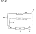
- FIG. 25 shows a freeze cycle of a freezer-refrigerator disclosed in the patent document 2.
- a freeze cycle 40 has a compressor 41; thanks to the compressor 41, a refrigerant flows in an arrow direction, whereby the freeze cycle 40 is operated.
- a heat radiator 42 is connected; branched at a three-way valve 46, first and second evaporators 44a, 44b are disposed in parallel with each other via first and second pressure reducers 43a, 43b. According to this, the heat radiator 42 is disposed in a high-temperature portion of the freeze cycle 40, while the first and second evaporators 44a, 44b are disposed in a low-temperature portion.
- the first and second evaporators 44a, 44b are disposed behind the refrigeration compartment and the freeze compartment, respectively. Near the first and second evaporators 44a, 44b, air blowers (not shown) are disposed, respectively. Thanks to driving of each air blower, cold air generated by heat exchange with the first and second evaporators 44a, 44b circulates in the refrigerator compartment and the freeze compartment, whereby the refrigeration compartment and the freeze compartment are cooled.
- patent documents 3, 4 disclose a dual freeze cycle that includes first and second freeze cycles which are operated by first and second compressors. In the first and second freeze cycles, a refrigerant including carbon dioxide flows, respectively. An intermediate heat exchanger, which performs heat exchange between a low-temperature portion of the first freeze cycle and a high-temperature portion of the second freeze cycle, is disposed; and in the high-temperature portion of the second freeze cycle, an evaporator is disposed.
- the intermediate heat exchanger in the low-temperature portion of the first freeze cycle is kept at a low temperature.
- the refrigerant in the second freeze cycle radiates heat in the intermediate heat exchanger to be condensed.
- An evaporator in a low-temperature portion of the second freeze cycle is kept at a temperature lower than the intermediate heat exchanger. According to this, it is possible to supply extremely cold air into a storing compartment.
- a receiver is disposed in a subsequent stage of the intermediate heat exchanger.
- the receiver separates the refrigerant, which flows from the intermediate heat exchanger, into a gas and a liquid; and outputs the liquid refrigerant. According to this, it is possible to secure a circulation amount of the refrigerant by decreasing bubbles contained in the refrigerant that flows in the evaporator; and prevent deterioration of the cooling capability.
- a patent document 5 discloses a conventional freezer-refrigerator.
- a freeze compartment is disposed in an upper portion of a main body portion and a refrigeration compartment is disposed in a lower portion of the main body portion.
- a mechanical compartment is disposed; in the mechanical compartment, first and second compressors are disposed.
- the first compressor operates a first freeze cycle and the refrigeration compartment is cooled by an evaporator disposed in a low-temperature portion of the first freeze cycle.
- the second compressor operates a second freeze cycle and the freeze compartment is cooled by an evaporator disposed in a low-temperature portion of the second freeze cycle.
- the refrigeration compartment and the freeze compartment are independently cooled, whereby it is possible to achieve energy saving.
- defrosting heaters are disposed below the first and second evaporators. By stopping the compressor and driving the defrosting heaters, the first and second evaporators are defrosted.
- a patent document 6 discloses a freezer-refrigerator that defrosts an evaporator by means of a freeze cycle.
- an evaporator is disposed in a low-temperature portion of the freeze cycle and a heat radiator is disposed in a high-temperature portion of the freeze cycle.
- the heat radiator is disposed on a metal rear plate or the like of the freezer-refrigerator; and thanks to operation of the freeze cycle, radiates heat into the outside air via the rear plate.
- the evaporator is cooled thanks to the operation of the freeze cycle; and a storing compartment is cooled by cold air that performs heat exchange with the evaporator.
- a refrigerant in the freeze cycle is made to flow in an opposite direction by a switching means.
- the evaporator is disposed in the high-temperature portion of the freeze cycle and raised in temperature, whereby the defrosting is performed.
- a freezer-refrigerator disclosed in a patent document 7 has first and second evaporators that are connected in parallel with a compressor which operates a freeze cycle.
- the first and second evaporators are disposed in a low-temperature portion of the freeze cycle and the flowing of a refrigerant is switched by a switching means.
- a cooling plate is mounted on a refrigerant pipe in which the refrigerant flows.
- the cooling plate covers a wide area of a rear surface of the refrigeration compartment and is exposed.
- the second evaporator is disposed in a duct that is disposed behind the freeze compartment; and many fms are mounted on a refrigerant pipe in which the refrigerant flows.
- An air blower is disposed in the duct.
- the first evaporator is lowered in temperature and the inside of the refrigeration compartment is cooled by cold heat that is radiated from the cooling plate. If the flow path of the refrigerant is switched to the second evaporator, the second evaporator is lowered in temperature.
- the air which flows in the duct thanks to driving of the air blower, and the second evaporator perform heat exchange with each other, whereby cold air is generated; and the cold air is output into the freeze compartment, whereby the freeze compartment is cooled.
- the refrigeration compartment refrigerates and preserves the stored things at, for example, 0°C to 5°C and is kept at a compartment temperature higher than the freeze compartment that freezes and preserves the stored things at, for example, -20°C.
- the first and second evaporators are disposed in parallel with each other, accordingly, kept at about the same temperature. Because of this, the first evaporator, which performs the cooling of the refrigeration compartment, is kept at a temperature lower than the temperature of the freeze compartment.
- the evaporator disposed in the low-temperature portion of the freeze cycle is able to sufficiently cool the refrigeration compartment at a temperature a few degrees lower than the temperature of the refrigeration compartment.
- thermodynamics it is known from a principle of thermodynamics that the lower the temperature of the low-temperature portion is, the lower the cooling effect of the freeze cycle becomes. Because of this, if the refrigeration compartment is cooled by means of the first evaporator that has a temperature extremely lower than the compartment temperature of the refrigeration compartment, the COP (Coefficient Of Performance) of the freeze cycle becomes low. Accordingly, there is a problem that power consumption of the freezer-refrigerator becomes large.
- the evaporator for generating the cold air is disposed in the second freeze cycle. Because of this, even if the dual freeze cycle is disposed in a freezer-refrigerator, the refrigeration compartment and the freeze compartment are cooled by the same evaporator. According to this, like the above description, the temperature of the evaporator becomes an extremely low temperature compared with the compartment temperature of the refrigeration compartment, and there is a problem that the power consumption of the freezer-refrigerator becomes large.
- the first and second compressors are disposed in the mechanical compartment that is disposed in the lower portion of the main body portion.
- the first and second compressors are point sound sources as well, so that sounds released from them are superposed.
- sounds, which have frequencies close to each other and the same phase are likely to be released from the respective compressors. If the sounds having the same phase are superposed, the sound-pressure level becomes double.
- a hum sound becomes likely to occur. Accordingly, there is a problem that the noise of the freezer-refrigerator becomes large.
- the first and second evaporators are raised in temperature by the defrosting heater to perform the defrosting, so that there is a problem that the power consumption of the freezer-refrigerator becomes large.
- a defrosting heater is not disposed, so that the power consumption is reduced.
- the heat radiator disposed in the high-temperature portion of the freeze cycle is disposed in the low-temperature portion during a time of defrosting, so that there is a problem that condensation occurs on the heat radiator and the rear plate.
- the refrigerant selectively flows in the first and second evaporators, so that it is impossible to cool the refrigeration compartment and the freeze compartment at the same time. Because of this, there is a problem that during a high load time immediately after the stored things are housed, it is impossible to obtain a sufficient cooling capability in the refrigeration compartment and the freeze compartment at the same time. Especially, the refrigeration compartment undergoes the radiation cooling, so that it takes a long time to lower the temperature; and the freeze compartment is not cooled enough during the high load time of the refrigeration compartment.
- a freezer-refrigerator includes:
- the first and second freeze cycles are operated by the first and second compressors; the first and second refrigerants flow, so that the low-temperature portion and high-temperature portion of the first and second freeze cycles are formed.
- the first refrigerant which has a high temperature and high pressure, flows in the first heat radiator of the high-temperature portion of the first freeze cycle to radiate heat, so that the first refrigerant is condensed.
- the first refrigerant which has a low temperature and low pressure, flows in the first evaporator of the low-temperature portion of the first freeze cycle and the intermediate heat exchanger, so that the refrigeration compartment is cooled by cold air which is lowered in temperature by the first evaporator.
- the second refrigerant which has a high temperature and high pressure, flows in the high-temperature portion of the second freeze cycle; and has heat sucked by the intermediate heat exchanger to radiate heat.
- the second refrigerant which has a low temperature and low pressure, flows in the second evaporator of the low-temperature portion of the second freeze cycle, so that the freeze compartment is cooled by cold air which is lowered in temperature by the second evaporator.
- the first evaporator and the intermediate heat exchanger may be disposed in series with each other or disposed in parallel with each other.
- the intermediate heat exchanger is disposed in a subsequent stage of the first evaporator.
- the first refrigerant after absorbing heat in the first evaporator, flows in the intermediate heat exchanger to perform heat exchange with the high-temperature portion of the second freeze cycle.
- the freezer-refrigerator having the above structure according to the present invention includes a second heat radiator disposed in the high-temperature portion of the second freeze cycle.
- the second refrigerant which has the high temperature and high pressure, flows in the second heat radiator of the high-temperature portion of the second freeze cycle and the intermediate heat exchanger, so that the second refrigerant radiates heat via the second heat radiator and the intermediate heat exchanger to be condensed.
- the intermediate heat exchanger is disposed in a subsequent stage of the second heat radiator.
- the second refrigerant after radiating heat via the second heat radiator, flows in the intermediate heat exchanger to perform heat exchange with the low-temperature portion of the first freeze cycle.
- heat exchange is performed between the second refrigerant flowing from the second evaporator and the first refrigerant after flowing in the first evaporator.
- the low-temperature second refrigerant flowing from the second evaporator absorbs heat from the first refrigerant before flowing in the first evaporator; the enthalpy of the first refrigerant decreases; and the first refrigerant as a refrigerant having a higher cooling capability flows in the first evaporator.
- heat exchange is performed between the second refrigerant flowing from the second evaporator and the second refrigerant before flowing into the second evaporator.
- the low-temperature second refrigerant flowing from the second evaporator absorbs heat from the second refrigerant before flowing in the second evaporator; the enthalpy of the second refrigerant decreases; and the second refrigerant as a refrigerant having a higher cooling capability flows in the second evaporator.
- freezer-refrigerator having the above structure according to the present invention includes:
- the intermediate heat exchange is disposed, so that it is possible to make compression ratios of a high-temperature cycle compressor and a low-temperature cycle compressor smaller than that of the conventional cycle; according to this, the compression efficiency increases, and it is possible to obtain the freezer-refrigerator that is excellent in energy saving characteristic.
- the third internal heat exchanger performs heat exchange between the first refrigerant flowing from the first heat radiator and the first refrigerant flowing from the intermediate heat exchanger.
- the second heat radiator disposed in the high-temperature portion of the second freeze cycle is disposed in a previous stage of the intermediate heat exchanger; and the second internal heat exchanger performs heat exchange between the second refrigerant flowing from the intermediate heat exchanger and the second refrigerant flowing from the second evaporator.
- the first internal heat exchanger performs heat exchange between the first refrigerant flowing from the third internal heat exchanger and the second refrigerant flowing from the second internal heat exchanger.
- freezer-refrigerator having the above structure according to the present invention includes:
- freezer-refrigerator having the above structure according to the present invention includes:
- the freezer-refrigerator having the above structure according to the present invention includes a receiver that is disposed in the flow path for the first refrigerant of intermediate heat exchanger; separates the first refrigerant into a gas and a liquid; and outputs a gas refrigerant.
- the first and second freeze cycles are operated by the first and second compressors; the first and second refrigerants flow, so that the low-temperature portion and high-temperature portion of the first and second freeze cycles are formed.
- the first refrigerant which has the low temperature and low pressure, flows in the first evaporator of the low-temperature portion of the first freeze cycle and the intermediate heat exchanger; and the refrigeration compartment is cooled by the cold air that is lowered in temperature by the first evaporator.
- the second refrigerant which has the high temperature and high pressure, flows in the high-temperature portion of the second freeze cycle; and has heat absorbed by the intermediate heat exchanger to radiate heat.
- the second refrigerant which has the low temperature and low pressure, flows in the second evaporator of the low-temperature portion of the second freeze cycle; and the freeze compartment is cooled by the cold air that is lowered in temperature by the second evaporator.
- the first refrigerant which flows in the intermediate heat exchanger, performs, in a mixed state of a gas and a liquid, heat exchange with the second refrigerant; thereafter, the first refrigerant in the gas state, which is separated by the receiver, performs heat exchange with the second refrigerant to absorb heat.
- the freezer-refrigerator having the above structure according to the present invention, in the intermediate heat exchanger, an upstream side of the first freeze cycle and a downstream side of the second freeze cycle perform heat exchange with each other; and a downstream side of the first freeze cycle and an upstream side of the second freeze cycle perform heat exchange with each other.
- the first refrigerant which flows in the intermediate heat exchanger and is in the mixed state of a gas and a liquid, performs heat exchange with the second refrigerant that has heat radiated by the intermediate heat exchanger.
- the first refrigerant which passes through the receiver and is in the gas state, performs heat exchange with the high-temperature second refrigerant.
- the intermediate heat exchanger includes:
- the freezer-refrigerator having the above structure according to the present invention includes the first and second heat radiators that are disposed in the high-temperature portions of the first and second freeze cycles, respectively; and the intermediate heat exchanger is disposed in a subsequent stage of the second heat radiator.
- the first refrigerant radiates heat via the first heat radiator; thereafter, flows in the first evaporator of the low-temperature portion and the intermediate heart exchanger.
- the second refrigerant radiates heat via the second heat radiator; thereafter, flows in the intermediate heat exchanger to perform heat exchange with the first refrigerant.
- the second refrigerant flowing from the second evaporator performs heat exchange with the second refrigerant that flows from the intermediate heat exchanger; thereafter, performs heat exchange with the first refrigerant that flows from the first heat radiator.
- the second refrigerant, which flows from the intermediate heat exchanger has heat absorbed by the second refrigerant, which flows from the second evaporator and has the low temperature; and the enthalpy decreases.
- the first refrigerant, which flows from the first heat radiator has heat absorbed by the second refrigerant, which flows from the second evaporator and has the low temperature; and the enthalpy decreases.
- the first and second refrigerants, which each have a high cooling capability flow in the first and second evaporators.
- the first and second refrigerants include isobutane.
- a boiling point of the first refrigerant is higher than a boiling point of the second refrigerant.
- the first refrigerant includes isobutene; and the second refrigerant includes propane or carbon dioxide.
- the freezer-refrigerator according to the present invention includes:
- the first and second freeze cycles are operated by the first and second compressors; the first and second refrigerants flow, so that the low-temperature portion and high-temperature portion of the first and second freeze cycles are formed.
- the refrigeration compartment is cooled by the first evaporator of the low-temperature portion of the first freeze cycle, while the freeze compartment is cooled by the second evaporator of the low-temperature portion of the second freeze cycle.
- the first and second compressors are disposed in the first and second mechanical compartments, which are disposed in the main body portion, respectively.
- the first mechanical compartment is disposed in the upper portion of the main body portion
- the second mechanical compartment is disposed in the lower portion of the main body portion. According to this, the first and second compressors are disposed away from each other.
- the freezer-refrigerator having the above structure according to the present invention includes an intermediate heat exchanger that performs heat exchange between a first heat exchange portion disposed in a subsequent stage of the first evaporator and a second heat exchange portion disposed in a high-temperature portion of the second freeze cycle.
- the first refrigerant which has the low temperature and low pressure, flows in the first heat exchange portion of the low-temperature portion of the first freeze cycle
- the second refrigerant which has the high temperature and high pressure
- heat of the second refrigerant is absorbed by the first refrigerant in the intermediate heat exchanger.
- the refrigeration compartment and the freeze compartment are vertically disposed in parallel with each other, and the first and second mechanical compartments are disposed near the refrigeration compartment and the freeze compartment, respectively; the first and second evaporators are disposed behind the refrigeration compartment and the freeze compartment, respectively; the intermediate heat exchanger is disposed between the first compressor and the second compressor, formed to vertically extend; the first heat exchange portion and the second heat exchange portion bend in a vertical direction; and refrigerant flow-in openings and refrigerant flow-out openings of the first and second heat exchange portions are disposed near the first mechanical compartment.
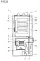
- the refrigeration compartment is disposed at an upper position of the main body portion; the first mechanical compartment, which includes the first compressor, is disposed in the upper portion of the main body portion; the freeze compartment is disposed at a lower position of the main body portion; and the second mechanical compartment, which includes the second compressor, is disposed in the lower portion of the main body portion.
- the first evaporator is disposed in the upper portion of the main body portion, while the second evaporator is disposed in the lower portion of the main body portion.
- the intermediate heat exchanger is so disposed as to extend vertically in the main body portion; and is so formed as to bend in a vertical direction.
- a refrigerant flow-in opening and a refrigerant flow-out opening are formed.
- the refrigerant flow-in opening is connected to the first evaporator, while the refrigerant flow-out opening is connected to the first compressor.
- the refrigerant flow-in opening is connected to the second compressor, while the refrigerant flow-out opening is connected to the second evaporator.
- freezer-refrigerator having the above structure according to the present invention includes:
- the first refrigerant which has the high temperature and high pressure, flows in the first heat radiator to radiate heat, so that the first refrigerant is condensed.
- the first refrigerant, which is condensed by the first heat radiator flows in the first pressure reducer, so that the first refrigerant is decompressed and expanded to become a damp vapor that has a low dry degree and a low temperature.
- the second refrigerant, which is condensed by the intermediate heat exchanger flows in the second pressure reducer, so that the second refrigerant is decompressed and expanded to become a damp vapor that has a low dry degree and a low temperature.
- the second refrigerant which flows from the second evaporator, performs heat exchange with the first pressure reducer in the first internal heat exchanger to absorb heat. According to this, the enthalpy of the first refrigerant decreases; and the first refrigerant having a higher cooling capability flows in the first evaporator.
- the second refrigerant which flows from the second evaporator, performs heat exchange with the second pressure reducer in the second internal heat exchanger to absorb heat. According to this, the enthalpy of the second refrigerant decreases; and the second refrigerant having a higher cooling capability flows in the second evaporator.
- the second internal heat exchanger is so disposed as to extend vertically; and the refrigerant flow-in side of the second pressure reducer is disposed in the upper portion of the main body portion.
- the refrigerant flow-out side of the second pressure reducer is connected to the second evaporator that is disposed in the lower portion.
- the first internal heat exchanger is so disposed as to continuously extend vertically from an upper end of the second internal heat exchanger.
- the refrigerant flow-in side of the first pressure reducer is disposed in the lower portion of the main body portion, while the refrigerant flow-out side of the first pressure reducer is connected to the first evaporator that is disposed in the upper portion.
- a first dryer which dehumidifies the first refrigerant before flowing into the first pressure reducer, is disposed in the second mechanical compartment; and a second dryer, which dehumidifies the second refrigerant before flowing into the second pressure reducer, is disposed in the first mechanical compartment.
- the first refrigerant moisture of which is removed by the first dryer
- the second refrigerator moisture of which is removed by the second dryer
- the first pressure reducer flows in the first pressure reducer
- the first dryer is disposed in the lower portion of the main body portion and connected to the refrigerant flow-in side of the first pressure reducer
- the second dryer is disposed in the upper portion of the main body portion and connected to the refrigerant flow-in side of the second pressure reducer.
- the second dryer is covered by a heat insulation member.
- the intermediate heat exchanger includes a dual pipe in which an inside pipe is covered by an outside pipe; the first refrigerant flows in the inside pipe to form the first heat exchange portion; and the second refrigerant flows in the outside pipe in a direction opposite to the first refrigerant to form the second heat exchange portion.
- the first refrigerant flowing in the inside pipe and the second refrigerant flowing in the outside pipe perform heat exchange via the inside pipe.
- the second heat radiator is disposed between the second compressor and the intermediate heat exchanger.
- the second refrigerant which has the high temperature and high pressure, flows in the second heat radiator to radiate heat, so that the second refrigerant is lowered in temperature.
- the second refrigerant, which is lowered in temperature by the second heat radiator, is further cooled by the intermediate heat exchanger to condense.
- the first and second internal heat exchangers are embedded in a rear wall of the heat insulation box body; and the second heat radiator is disposed on a rear surface of the main body portion.
- the intermediate heat exchanger is embedded in the rear wall of the heat insulation box body.
- an accumulator for separating a gas and a liquid from each other is disposed on a refrigerant flow-out side of the second evaporator and is not disposed on a refrigerant flow-out side of the first evaporator.
- the second refrigerant flowing from the second evaporator is separated into a gas and a liquid; and the gas refrigerant is sent to the second compressor.
- the first refrigerant which flows from the first evaporator and in which a gas and a liquid are mixed with each other, flows in the intermediate heat exchanger; and thanks to heat exchange with the high-temperature portion of the second freeze cycle, the first refrigerant becomes a gas refrigerant and is sent to the first compressor.
- a heat insulation wall for partitioning the refrigeration compartment and the freeze compartment has a heat insulation performance in a level that is equal to that of a circumferential wall of the heat insulation box body.
- part of heat radiation from the first heat radiator is used for a drained water process and prevention of condensation in the freezer-refrigerator.
- the present invention includes:
- the first and second freeze cycles are operated by the first and second compressors; the first and second refrigerants flow, so that the low-temperature portion and high-temperature portion of the first and second freeze cycles are formed.
- the first refrigerant which has a low temperature and low pressure, flows in the first heat radiator of the high-temperature portion of the first freeze cycle, so that the first refrigerant is cooled by the cold air that is lowered in temperature by the first evaporator.
- the second refrigerant which has a low temperature and low pressure, flows in the second evaporator of the low-temperature portion of the second freeze cycle, so that the freeze compartment is cooled by the cold air that is lowered in temperature by the second evaporator.
- the operation of the second freeze cycle is stopped, while the first freeze cycle is operated.
- the high-temperature portion of the first freeze compartment and the second evaporator perform heat exchange, so that the second evaporator is raised in temperature and the defrosting is performed.
- freezer-refrigerator having the above structure according to the present invention includes:
- a flow path of the first refrigerant is switched to the first heat radiator by the three-way valve.
- the first and second evaporators are cooled and heat is radiated from the first heat radiator.
- the flow of the first refrigerant which is from the refrigerant flow-out side of the first heat radiator to the defrosting heat exchanger, is stopped by the check valve.
- the flow path of the first refrigerant is switched to the defrosting heat exchanger by the threes-way valve.
- the first evaporator is cooled and heat is radiated from the defrosting heat exchanger.
- the second evaporator performs heat exchange with the defrosting heat exchanger, so that the second evaporator is raised in temperature and the defrosting is performed.
- the check valve is disposed near a joining point of a refrigerant flow-out side of the first heat radiator and a refrigerant flow-out side of the defrosting heat exchanger. According to this, the check valve and the defrosting heat exchanger are disposed away from each other. Because of this, when the flow path of the first refrigerant is switched to the first heat radiator by the three-way valve, the temperature rise of the second evaporator due to the first refrigerant, which flows from the first heat radiator and has the high temperature, is reduced.
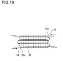
- the second evaporator and the defrosting heat exchanger include first and second refrigerant pipes in which the first and second refrigerants flow, respectively; and the first and second refrigerant pipes are connected to each other by a plurality of fins. According to this structure, heat of the first refrigerant having the high temperature is conducted to the second evaporator via the fins that connect the first and second refrigerant pipes to each other.
- the second evaporator and the defrosting heat exchanger include first and second refrigerant pipes in which the first and second refrigerants flow, respectively; and the first and second refrigerant pipes are disposed side by side. According to this structure, heat of the first refrigerant having the high temperature is conducted to the second evaporator via a border wall between the first and second refrigerant pipes.
- the sectional area of a refrigerant pipe of the defrosting heat exchanger is half of the sectional area of a refrigerant pipe of the first evaporator. According to this structure, the internal volume of the refrigerant pipe of the defrosting heat exchanger is made small and a large amount of the refrigerant is prevented from collecting in the defrosting heat exchanger after the defrosting.
- the first compressor before defrosting the second evaporator, the first compressor is stopped for a predetermined period.
- the first compressor is stopped and the three-way valve is switched to the defrosting heat exchanger, the compartment temperature of the refrigeration compartment rises; and if the predetermined period elapses, the first compressor is driven.
- the first refrigerant flows in the defrosting heat exchanger, so that the second evaporator is defrosted and the refrigeration compartment is cooled.
- the three-way valve may be switched to the defrosting heat exchanger.
- the present invention includes:
- the first and second freeze cycles are operated by the first and second compressors; the first and second refrigerants flow, so that the low-temperature portion and high-temperature portion of the first and second freeze cycles are formed.
- the first refrigerant which has a low temperature and low pressure, flows in the refrigerant pipe of the first evaporator of the first freeze cycle, so that cold heat is radiated from the cooling plate and the refrigeration compartment is cooled.
- the second refrigerant which has a low temperature and low pressure, flows in the second evaporator of the low-temperature portion of the second freeze cycle, so that the freeze compartment is cooled by the cold air which is lowered in temperature by the second evaporator
- freezer-refrigerator having the above structure according to the present invention includes:
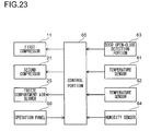
- the temperature and the humidity of the refrigeration compartment are detected by the temperature sensor and the humidity sensor.
- the dew point temperature of the refrigeration compartment is obtained from calculation and the like based on the detection results from the temperature sensor and the humidity sensor; and the first evaporator is kept at the dew point temperature or below. According to this, moisture of the outside air, which flows in thanks to the opening and closing of the door, condenses on a surface of the cooling plate.
- an intermediate heat exchanger which performs heat exchange between the low-temperature portion of the first freeze cycle and a high-temperature portion of the second freeze cycle, is disposed.
- the first refrigerant which has the low temperature and low pressure, flows in the first evaporator of the low-temperature portion of the first freeze cycle and the intermediate heat exchanger.
- the second refrigerant which has the high temperature and high pressure, flows in the high-temperature portion of the second freeze cycle; and has heat absorbed by the intermediate heat exchanger to radiate heat.
- the first evaporator and the intermediate heat exchanger may be disposed in series with each other or disposed in parallel with each other.
- an insulation compartment having a temperature lower than a temperature of an upper portion is disposed; and in the refrigerant pipe of the first evaporator, a refrigerant flows from lower to upper.
- the insulation compartments such as a chilled compartment, an ice compartment and the like which have a low temperature.
- the cooling plate in the lower portion of the first evaporator touches the refrigerant pipe, which has the low temperature, to cool the insulation compartments.
- a cooling storage unit includes:
- the cooling storage unit having the above structure according to the present invention includes:
- the cooling storage unit having the above structure according to the present invention includes a receiver that is disposed in a first freeze cycle of the intermediate heat exchanger, separates the first refrigerant into a gas and a liquid, and outputs the liquid refrigerant.
- the cooling storage unit having the above structure according to the present invention includes:
- the cooling storage unit having the above structure according to the present invention includes:
- the refrigeration compartment is cooled by the first evaporator that is disposed in the first freeze cycle, while the freeze compartment is cooled by the second evaporator that is disposed in the second freeze cycle. Because of this, it is possible make a temperature difference between the first evaporator and the refrigeration compartment small; and it is possible to drive the first and second compressors with a high efficiency. Accordingly, the COP of the freeze cycle increases; and it is possible to reduce power consumption of the freezer-refrigerator.
- the receiver is disposed in the first freeze cycle of the intermediate heat exchanger, so that even if a heat load on the freezer-refrigerator increases, the first refrigerant as the gas refrigerant performs the heat exchange with the second refrigerant. According to this, the first refrigerant surely rises in temperature and is sent to the first compressor, so that it is possible to keep the capability of the intermediate heat exchanger.
- the first refrigerant as the gas refrigerant which flows from the receiver, absorbs heat to rise in temperature, thereafter, flows in the first compressor, so that it is possible to reduce a cold heat loss.
- one of the first and second mechanical compartments, in which the first and second compressors are disposed is disposed in the upper portion of the main body portion, while the other is disposed in the lower portion, so that the first and second compressors, which are also point sound sources, are disposed away from each other.
- the sound-pressure level of the point sound source decreases as the distance increases; and when a user comes close to one point sound source, the user is away from the other point sound source, so that the noise level the user hears becomes small.
- the first and second compressors are disposed in the compartments different from each other, so that the same-phase sound and the same-frequency sound become unlikely to occur. According to this, the sound pressure due to the sounds, overlapping with each other, from the first and second compressors becomes low; and it is possible to reduce occurrence of a hum. Accordingly, it is possible to lower the noise of the freezer-refrigerator.
- the second evaporator of the second freeze cycle is defrosted by the heat of the high-temperature portion of the first freeze cycle, so that first heat radiator of the first freeze cycle and the second heat radiator of the second freeze cycle do not reach a low temperature. Accordingly, it is possible to prevent condensation on the rear plate and the like of the freezer-refrigerator. Besides, it is unnecessary to additionally dispose a heater that defrosts the second evaporator, so that it is possible to curb temperature rise caused by a heater and the like during the defrosting time. Besides, most of the heat, which heats the second evaporator during the defrosting time, is heat from the refrigeration compartment, so that it is possible to cool the refrigeration compartment performing the defrosting. Accordingly, it is possible to curb the power consumption caused by the defrosting; and keep the power consumption of the freezer-refrigerator low.
- the first and second freeze cycles are operated by the first and second compressors, respectively; the refrigeration compartment and the freeze compartment are cooled by the first and second evaporators; and the first evaporator has the cooling plate, so that it is possible to prevent the drying of the stored things; and during a high-load time and the like immediately after the stored things are housed, it is possible to obtain a sufficient cooling capability of the refrigeration compartment and the freeze compartment.
- the high-load time of the refrigeration compartment it is possible to lower the second evaporator in temperature, so that it is possible to prevent insufficient cooling of the freeze compartment.
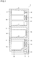
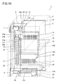
- FIG. 1 is a side sectional view showing a freezer-refrigerator according to a first embodiment.
- a freezer-refrigerator 1 is provided with a refrigeration compartment 2 in an upper portion for refrigerating and preserving stored things.
- a vegetable compartment 3 which is kept at a temperature that is higher than a temperature of the refrigeration compartment 2 and suitable for preserving vegetables, is disposed.
- a freeze compartment 4 for freezing and preserving stored things is disposed in a lower portion of the freezer-refrigerator 1.
- a front surface of the refrigeration compartment 2 is opened and closed by a rotatable heat insulation door 2a.
- Front surfaces of the vegetable compartment 3 and the freeze compartment 4 are opened and closed by drawer type of heat insulation doors 3a and 4a that are unitary with housing cases 3b and 4b, respectively.
- a mechanical compartment 5 is disposed In the mechanical compartment 5, first and second compressors 11 and 21, which operate first and second freeze cycles 10 and 20 (see Fig. 2 ) described in detail later, respectively, are disposed.
- first and second compressors 11 and 21 which operate first and second freeze cycles 10 and 20 (see Fig. 2 ) described in detail later, respectively, are disposed.
- a first evaporator 14 connected to the first compressor 11 is disposed; and over the first evaporator 14, a refrigeration compartment air blower 15 is disposed.
- a second evaporator 24 connected to the second compressor 21 is disposed; and over the second evaporator 24, a freeze compartment air blower 25 is disposed.
- a defrosting heater 51 is disposed below the first evaporator 14, a defrosting heater 51 is disposed.
- Cold air cooled by heat exchange with the first evaporator 14 is output into the refrigeration compartment 2 by the refrigeration compartment air blower 15.
- the cold air flows in the refrigeration compartment 2 and flows in the vegetable compartment 3 that communicates with the refrigeration compartment 2.
- the cold air flowing in the vegetable compartment 3 flows in the vegetable compartment 3 and returns to the first evaporator 14. According to this, the refrigeration compartment 2 and the vegetable compartment 3 are cooled.
- Cold air cooled by heat exchange with the second evaporator 24 is output into the freeze compartment 4 by the freeze compartment air blower 25.
- the cold air output into the freeze compartment 4 flows in the freeze compartment 4 and returns to the second evaporator 24. According to this, the freeze compartment 4 is cooled.
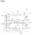
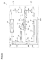
- FIG. 2 shows a freeze cycle of the freezer-refrigerator 1.
- a freeze cycle 30 of the freezer-refrigerator 1 is a cascade type of dual freeze cycle in which the first and second freeze cycles 10, 20 are connected to each other by an intermediate heat exchanger 31.
- the first freeze cycle 10 forms a high temperature cycle while the second freeze cycle 20 forms a low temperature cycle.
- heat exchange is performed between a low-temperature portion of the first freeze cycle 10 and a high-temperature portion of the second freeze cycle 20 by the intermediate heat exchanger 31. According to this, a low-temperature portion of the second freeze cycle 20 is kept at a temperature lower than the low-temperature portion of the first freeze cycle 10.
- the first freeze cycle 10 operated by the first compressor 11 has: a first heat radiator 12, a first pressure reducer 13, and a first evaporator 14 that are connected by a refrigerant pipe 10a.
- a first refrigerant such as isobutane and the like flows in an arrow S1 direction.
- the first refrigerant flows and circulates via the first compressor 11, the first heat radiator 12, the first pressure reducer 13, the first evaporator 14 and the first compressor 11 in this order.
- the second freeze cycle 20 operated by the second compressor 21 has: a second heat radiator 22, a second pressure reducer 23, and a second evaporator 24 that are connected by a refrigerant pipe 20a.
- a second refrigerant such as isobutane and the like flows in an arrow S2 direction.
- the second refrigerant flows and circulates via the second compressor 21, the second heat radiator 22, the second pressure reducer 23, the second evaporator 24 and the second compressor 21 in this order.
- a heat exchange portion 31a disposed in the first freeze cycle 10 and a heat exchange portion 31c disposed in the second freeze cycle 20 are disposed side by side; and so formed as to be able to perform heat exchange with each other via a wall surface.
- the heat exchange portion 31a is disposed in a subsequent stage of the first evaporator 14 while the heat exchange portion 31c is disposed in a subsequent stage of the second heat radiator 22.
- first and second internal heat exchangers 32, 33 are disposed.
- a heat exchange portion 32a disposed in the first freeze cycle 10 and a heat exchange portion 32b disposed in the second freeze cycle 20 are disposed side by side; and so formed as to be able to perform heat exchange with each other via a wall surface.
- the heat exchange portion 32a is disposed in a subsequent stage of the first heat radiator 12; and the first refrigerant having a high temperature before flowing in the first evaporator 14 flows in the heat exchange portion 32a.
- the heat exchange portion 32b is disposed in a subsequent stage of the second evaporator 24; and the second refrigerant having a low temperature after flowing from the second evaporator 24 flows in the heat exchange portion 32b.
- the first pressure reducer 13 includes a capillary tube
- the heat exchange portion 32a may double as the first pressure reducer 13.
- a heat exchange portion 33a disposed in a subsequent portion of the heat exchanger 31c and a heat exchange portion 33b disposed in a subsequent stage of the second evaporator 24 are disposed side by side; and so formed as to be able to perform heat exchange with each other via a wall surface.
- the heat exchange portion 33a the second refrigerant having a high temperature before flowing in the second evaporator 24 flows, while in the heat exchange portion 33b, the second refrigerant having a low temperature after flowing from the second evaporator 24 flows.
- the heat exchange portion 33a may double as the second pressure reducer 23.
- the first and second refrigerants flow in the refrigerant pipes 10a and 20a, respectively.
- the first and second compressors 11, 21 compress the first and second refrigerants to a high temperature and a high pressure, while the first and second pressure reducers 13 and 23 decompress and expand the first and second refrigerants to a low temperature and a low pressure.
- the first and second refrigerants flow from the first and second compressors; and thereafter flow in the first and second pressure reducers 13, 23, the first and second refrigerants serve as high-temperature portions of the first and second freeze cycles 10, 20.
- the first and second refrigerants flow from the first and second pressure reducers 13, 23; and thereafter flow in the first and second compressors 11, 21, the first and second refrigerants serve as low-temperature portions of the first and second freeze cycles 10, 20.
- the first refrigerant which is compressed by the first compressor 11 and has the high temperature and high pressure, is deprived of heat by the surrounding air via the first heat radiator 12 to condense.
- the first refrigerant which is liquefied by the first heat radiator 12, is deprived of heat by the second refrigerant in the low-temperature portion of the second freeze cycle 20 in the first internal heat exchanger 32 to be further lowered in temperature.
- the first refrigerant which is cooled to a large over-cooling degree by the first internal heat exchanger 32 and in the liquefied state, flows in the first pressure reducer 13.
- the first refrigerant is decompressed and expanded by the first pressure reducer 13 and becomes a damp vapor that has a low dry degree and a low temperature.
- the first refrigerant which becomes the low-temperature damp vapor, flows in the first evaporator 14, deprives the cold air in the refrigeration compartment 2 of heat to evaporate; and becomes a damp vapor that has a higher dry degree.
- the first refrigerant which flows from the first evaporator 14 and is in the damp vapor state, flows in the intermediate heat exchanger 31, deprives the second refrigerant in the high-temperature portion of the second freeze cycle of heat to evaporate; and becomes an over-heated vapor.
- the first refrigerant which becomes the over-heated vapor, returns to the first compressor 11. According to this, the first refrigerant circulates, whereby the first freeze cycle 10 is operated.
- the second refrigerant which is compressed by the second compressor 21 and has the high temperature and high pressure, is deprived of heat by the surrounding air via the second heat radiator 22.
- the second refrigerant which is lowered in temperature by the second heat radiator 22, flows in the intermediate heat exchanger 31 and is deprived of heat by the first refrigerant in the low-temperature portion of the first freeze cycle 10 to be further cooled to condense.
- the liquefied second refrigerant is deprived of heat by the second refrigerant in the low-temperature portion of the second freeze cycle 20 in the second internal heat exchanger 33 to be further lowered in temperature.
- the second refrigerant which is cooled to a large over-cooling degree by the second internal heat exchanger 33 and in the liquefied state, flows in the second pressure reducer 23.
- the second refrigerant is decompressed and expanded by the second pressure reducer 23 and becomes a damp vapor that has a low temperature.
- the second refrigerant which becomes the low-temperature damp vapor, flows in the second evaporator 24, deprives the cold air in the freeze compartment 4 of heat to evaporate; and becomes a damp vapor.
- the second refrigerant which flows from the second evaporator 24 and is in the damp vapor state, is guided to the second internal heat exchanger 33 and the first internal heat exchanger 32; deprives the high-temperature second refrigerant and the high-temperature first refrigerant of heat to become an over-heated vapor.
- the second refrigerant which becomes the over-heated vapor, returns to the second compressor 21. According to this, the second refrigerant circulates, whereby the second freeze cycle 20 is operated.
- the second compressor 21 is driven after the first compressor 11 is driven and the temperature of the intermediate heat exchanger 31 decreases. And, the temperatures of the refrigeration compartment 2 and the freeze compartment 4 and a temperature difference between the heat exchange portions 31a and 31c of the intermediate heat exchanger 31 are monitored; and the rotation speeds of the first and second compressors 11, 21 are controlled by inverter control such that these speeds become predetermined values.
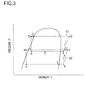
- Fig. 3 shows a pressure-enthalpy diagram (P-H diagram) of the freeze cycle 30.
- a vertical axis indicates pressure while a lateral axis indicates enthalpy.
- the respective points A, B, C, D, E, E', a, b, b', c, d, e, and f correspond to the respective points of the freeze cycle shown in Fig. 2 .
- the A-B indicates a process in the first compressor 11.
- the B-C indicates a process in the first heat radiator 12.
- the C-D indicates a process in the heat exchange portion 32a of the first internal heat exchanger 32.
- the D-E indicates a process in the first pressure reducer 13.
- the E-E' indicates a process in the first evaporator 14.
- the E'-A indicates a process in the heat exchange portion 31a of the intermediate heat exchanger 31.
- the a-b indicates a process in the second compressor 21.
- the b-b' indicates a process in the second heat radiator 22.
- the b'-c indicates a process in the heat exchange portion 31c of the intermediate heat exchanger 31.
- the c-d indicates a process in the heat exchange portion 33a of the second internal heat exchanger 33.
- the d-e indicates a process in the second pressure reducer 23.
- the e-f indicates a process in the second evaporator 24.
- the f-a indicates processes in the heat exchange portion 33b of the second internal heat exchanger 33 and the heat exchange portion 32b of the first internal heat exchanger 32.
- the first and second freeze cycles 10, 20 are filled with the same refrigerant (e.g., isobutane), so that a temperature relationship and a pressure relationship between the first and second freeze cycles 10, 20 are easily understandable in the PH-diagram.
- a pressure PA at the A point of the first freeze cycle 10 is slightly lower than a pressure Pb at the b point of the second freeze cycle 20. This is because the first freeze cycle 10 deprives the second freeze cycle 20 of heat.
- the evaporation temperatures of the first and second evaporators 44a, 44b are about a temperature indicated by the e-f in Fig. 3 .
- the evaporation temperature of the first evaporator 14 which cools the refrigeration compartment 2 according to the present embodiment, is indicated by the E-F in Fig. 3 .
- the pressure P is, the higher the temperature is, so that the evaporation temperature of the first evaporator 14 becomes higher than the temperature in the case of the single freeze cycle.
- Fig. 4 shows a relationship between an adiabatic compression efficiency and a compression ratio of a positive displacement compressor according to " Guide and Data Book" (1961, p. 498) from ASHRAE (American Society of Heating, Refrigerating and Air-Conditioning Engineers ).
- a vertical axis indicates the adiabatic compression efficiency while a lateral axis indicates the compression ratio.
- most of the compressors used in usual freezer-refrigerators today are positive displacement type. According to experimental data of refrigerants R12 and R22, it is possible to say that other refrigerants have the same tendency. According to this figure, the smaller the compression ratio of the compressor is, the higher the adiabatic compression efficiency of the compressor becomes.
- the compression ratio of the conventional single freeze cycle 40 (see Fig. 25 ) is about 8.
- the compression ratios of the first and second freeze cycles 10, 20 each become abut 2 to 3. Accordingly, both of the compression ratios of the first and second freeze cycles 10, 20 are smaller than the conventional, so that it is possible to drive the first and second compressors 11, 21 with a high efficiency.
- the refrigeration compartment 2 is cooled by the first evaporator 14 disposed in the first freeze cycle 10, while the freeze compartment 4 is cooled by the second evaporator 24 disposed in the second freeze cycle 20. Because of this, it is possible to make the temperature difference between the first evaporator 14 and the refrigeration compartment 2 small; and drive the first and second compressors 11, 21 with a high efficiency. Accordingly, the COP of the freeze cycle 30 increases from the conventional, and it is possible to reduce the power consumption of the freezer-refrigerator 1.
- the intermediate heat exchanger 31 may be disposed in parallel with the first evaporator 14. However, if the intermediate heat exchanger 31 is disposed in the subsequent stage of the first evaporator 14 in series, the first refrigerant flows in the first evaporator 14 before the second refrigerant is deprived of heat by the intermediate heat exchanger 31. Accordingly, the first evaporator 14 deprives the air in the refrigeration compartment 2 of heat without lowering the temperature of the air in the refrigeration compartment 2 by means of heat exchange that uses latent heat, so that it is possible to increase the cooling efficiency.
- the second heat radiator 22 is provided which is disposed in the high-temperature portion of the second freeze cycle 20, so that it is possible to further lower the radiation heat of the entire first and second freeze cycles 10, 20. Accordingly, the COP of the freeze cycle 30 increases.
- the intermediate heat exchanger 31 may be disposed in parallel with the second heat radiator 22. However, the intermediate heat exchanger 31 is disposed in the subsequent stage of the second heat radiator 22, so that the second refrigerant flows in the second heat radiator 22 before the second refrigerant is deprived of heat by the first refrigerant in the intermediate heat exchanger 31. Accordingly, after the second refrigerant performs heat exchange in the second heat radiator 22 to radiate heat, the second refrigerant is cooled by the intermediate heat exchanger 31, so that it is possible to more efficiently perform the heat exchange.
- the first internal heat exchanger 32 is disposed which performs the heat exchange between: the second refrigerant flowing from the second evaporator 24; and the first refrigerant before flowing in the first evaporator 14, so that it is possible to lower the enthalpy of the first refrigerant; and further increase the cooling capability of the first refrigerant that flows in the first evaporator 14.
- the second internal heat exchanger 33 is disposed which performs the heat exchange between: the second refrigerant flowing from the second evaporator 24; and the second refrigerant before flowing in the second evaporator 24, so that it is possible to lower the enthalpy of the second refrigerant; and further increase the cooling capability of the second refrigerant that flows in the second evaporator 24.
- the second refrigerant which flows from the second evaporator 24, is heated to about the ambient temperature during a heat absorption process f-a in Fig. 3 . Because of this, a suction pipe of the second compressor 21 disposed in the mechanical compartment does not deprive the surrounding air of heat, so that it is possible to curb a heat loss. Besides, the temperature of the second refrigerant compressed by the second compressor 21 becomes higher than the ambient temperature, so that it becomes possible to radiate heat from the second heat radiator 22 into the surrounding area during a heat radiation process b-b' in Fig. 3 .
- the heat radiation level of the entire freeze cycle 30 is high; and an output temperature Tb from the second compressor 21 is lower than an output temperature TB from the first compressor 11. Because of this, it is impossible to sufficiently raise the temperature of the refrigerant, which is sucked into the second compressor 21, by means of the second internal heat exchanger 33 only.
- the first internal heat exchanger 32 in addition to the second internal heat exchanger 33, it is possible to raise the temperature of the second refrigerant sucked into the second compressor 21 such that the temperature of the second refrigerant after compression becomes over the ambient temperature. According to this, it becomes possible to radiate heat from the second heat radiator 22 into the surrounding area during the heat radiation process b-b' in Fig. 3 .
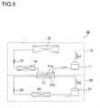
- Fig. 5 is a view showing a freeze cycle of the freezer-refrigerator 1 according to a second embodiment.
- the same portions as those shown in Fig. 1 to Fig. 4 described above are indicated by the same reference numbers.
- the second heat radiator 22, the first and second internal heat exchangers 32 and 33 are removed from the first embodiment.
- the other portions are the same as the first embodiment.
- the second heat radiator 22 and the first and second internal heat exchangers 32, 33 are removed from the first embodiment, so that it is impossible to use the effects of the first and second internal heat exchangers 32, 33; and that the COP of the freeze cycle 30 slightly decreases.
- the COP of the freeze cycle 30 slightly decreases.
- the refrigeration compartment 2 is cooled by the first evaporator 14 disposed in the first freeze cycle 10, while the freeze compartment 4 is cooled by the second evaporator 24 disposed in the second freeze cycle 20. Because of this, it is possible to make the temperature difference between the first evaporator 14 and the refrigeration compartment 2 small; and drive the first and second compressors 11, 21 with a high efficiency. Accordingly, the COP of the freeze cycle 30 increases from the conventional, and it is possible to reduce the power consumption of the freezer-refrigerator 1.
- Fig. 6 shows a freeze cycle of the freezer-refrigerator 1 according to a third embodiment.
- a first receiver 17 is disposed in the flow path for the first refrigerant of the intermediate heat exchanger 31, while a second receiver 27 is disposed in a downstream with respect to the second evaporator 24.
- the other portions are the same as the first embodiment.
- the first and second receivers 17, 27 separate a gas and a liquid from each other, store the liquid refrigerant and output the gas refrigerant.
- the first receiver 17 prevents the liquid refrigerant from flowing in the first compressor 11, while the second receiver 27 prevents the liquid refrigerant from flowing in the second compressor 21.
- Fig. 7 is a view showing details of the intermediate heat exchanger 31.
- the heat exchange portions 31a, 31b disposed in the first freeze cycle 10 and the heat exchange portions 31c, 31d disposed in the second freeze cycle 20 are disposed side by side; and so formed as to be able to perform heat exchange with each other via a wall surface.
- the heat exchange portion 31a is disposed in the subsequent stage of the first evaporator 14, while the heat exchange portion 31d is disposed in the subsequent stage of the second heat radiator 22.
- the heat exchangers 31a, 31b are disposed in an upstream and a downstream with respect to the first receiver 17, respectively. According to this, in the heat exchange portion 31a, the first refrigerant, in which a gas and a liquid are mixed with each other, is given vaporization heat (latent heat) to vaporize, while in the heat exchange portion 31b, the first refrigerant in a gas state is given sensible heat to rise in temperature.
- the heat exchange portion 31a in an upstream of the first freeze cycle 1 is close to the heat exchange portion 31c in a downstream of the second freeze cycle 20 to perform heat exchange.
- the heat exchange portion 31b in a downstream of the first freeze cycle 1 is close to the heat exchange portion 31d in an upstream of the second freeze cycle 20 to perform heat exchange.
- the lengths of the heat exchange portions 31c, 31d are set such that the heat exchange portion 31d radiates sensible heat chiefly from the second refrigerant that has a high temperature; and the second refrigerant, which falls in temperature in the heat exchange portion 31d, radiates condensation heat (latent heat) chiefly at the heat exchange portion 31c.
- the heat exchange portions 31a, 31c each constitute a latent-heat exchange portion that gives the latent heat of the second refrigerant as the latent heat of the first refrigerant
- the heat exchange portions 31b, 31d each constitute a sensible-heat exchange portion that gives the sensible heat of the second refrigerant as the sensible heat of the first refrigerant.
- the first refrigerant which flows from the first evaporator 14 and is in a damp vapor state, flows in the heat exchange portion 31a of the intermediate heat exchanger 31.
- the first refrigerant in the heat exchange portion 31a deprives the second refrigerant in the heat exchange portion 31c of latent heat to vaporize; and flows in the first receiver 17.
- the first refrigerant which flows in the first receiver 17, is separated into a gas and a liquid; the liquid refrigerant is stored and the gas refrigerant is output.
- the first refrigerant which is output from the first receiver 17 and in the gas state, deprives the heat exchange portion 31d of sensible heat chiefly by means of the heat exchange portion 31b to rise in temperature; and becomes an over-heated vapor.
- the second refrigerant which is lowered in temperature by the second heat radiator 22, flows in the heat exchange portion 31d of the intermediate heat exchanger 31.
- the second refrigerator which flows in the heat exchange portion 31d, is deprived of latent heat chiefly by the first refrigerant in the heat exchange portion 31b to be further cooled.
- the second refrigerant which is lowered in temperature and in the gas state, flows in the heat exchange portion 31c and is deprived of latent heat chiefly by the first refrigerant in the heat exchange portion 31a to condense.
- the second refrigerant which condenses, is deprived of heat by the second refrigerants in the low-temperature portion of the second freeze cycle 20 to be further lowered in temperature.
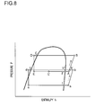
- Fig. 8 shows a pressure-enthalpy diagram (P-H diagram) of the freeze cycle 30 according to the present embodiment.
- a vertical axis indicates pressure while a lateral axis indicates enthalpy.
- the respective points A, B, C, D, E, E', F, a, b, b', b", c, d, e, and f correspond to the respective points of the freeze cycle shown in Fig. 6 ; a point F and a point b" are added to Fig. 3 described above.
- the E'-F indicates a process in the heat exchange portion 31a of the intermediate heat exchanger 31.
- the F-A indicates a process in the heat exchange portion 31b of the intermediate heat exchanger 31.
- the b'-b" indicates a process in the heat exchange portion 31d of the intermediate heat exchanger 31.
- the b"-c indicates a process in the heat exchange portion 31c of the intermediate heat exchanger 31.
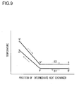
- Fig. 9 is a view showing a relationship between a position and a temperature of the intermediate heat exchanger 31.
- Fig. 11 shows a relationship between a position and a temperature of the intermediate heat exchanger 31 of a freeze cycle 30' shown in Fig. 10 .
- the first receive 17 is disposed in a subsequent stage of the intermediate heat exchanger 31.
- the other portions are the same as the freeze cycle 30 shown in Fig. 25 described above.
- vertical axes indicate the temperature and lateral axes indicate the position of the intermediate heat exchanger 31.
- the respective points A, F, E', b', b", and c correspond to the respective points of the freeze cycles 30, 30' shown in Fig. 25 and Fig. 20 .
- the second refrigerant undergoes heat radiation in the heat exchange portion 31d (b'-b"); and is condensed by the heat exchange portion 31 c (b" -c).
- the first refrigerant evaporates in the heat exchange portion 31a (E' -F); and evaporates in the heat exchange portion 31b (F-A) as well.
- the temperature difference between the first and second refrigerants in the heat exchange portion 31b becomes large, so that a loss due to the heat exchange is large.
- the first refrigerant which is the gas refrigerant flowing from the first receiver 17, does not absorb heat from the second freeze cycle 20, so that the first refrigerant flows in the first compressor 11 keeping the evaporation temperature unchanged. Accordingly, a cold heat loss is likely to occur.
- the first refrigerant evaporates in the heat exchange portion 31a (E'-F); and undergoes heat absorption in the heat exchange portion 31b (F-A). Because of this, in the intermediate heat exchanger 31, the latent-heat exchange and the sensible-heat exchange are performed matching with each other. Accordingly, it is possible to curb the temperature difference to the smallest limit; and reduce an effective energy loss caused by the heat exchange. Besides, the first refrigerant absorbs heat to rise in temperature, thereafter, flows in the first compressor 11, so that it is possible to reduce the cold heat loss.
- the refrigeration compartment 2 is cooled by the first evaporator 14 disposed in the first freeze cycle 10, while the freeze compartment 4 is cooled by the second evaporator 24 disposed in the second freeze cycle 20. Because of this, it is possible to make the temperature difference between the first evaporator 14 and the refrigeration compartment 2 small; and drive the first and second compressors 11, 21 with a high efficiency. Accordingly, the COP of the freeze cycle 30 increases from the conventional, and it is possible to reduce the power consumption of the freezer-refrigerator 1.
- the first receiver 17 is disposed in the flow path for the first refrigerant of the intermediate heat exchanger 31, so that even if the heat load on the freezer-refrigerator 1 changes, the first refrigerant, which is the gas refrigerant, performs the heat exchange with the second refrigerant. According to this, the first refrigerant surely rises in temperature and is sent to the first compressor 11, so that it is possible to keep the capability of the intermediate heat exchanger 31.
- the first refrigerant, which is the gas refrigerant flowing from the first receiver 17 absorbs heat to rise in temperature, thereafter, flows in the first compressor 11, so that it is possible to reduce the cold heat loss.
- the heat exchange portion 31a in the upstream of the first freeze cycle 10 and the heat exchange portion 31c in the downstream of the second freeze cycle 20 perform the heat exchange with each other
- the heat exchange portion 31b in the downstream of the first freeze cycle 10 and the heat exchange portion 31d in the upstream of the second freeze cycle 20 perform the heat exchange with each other, so that the first refrigerant in the gas state flowing from the first receiver 17 and the second refrigerant having the high temperature perform the heat exchange with each other.
- the sensible heat due to the heat radiation from the second refrigerant is used as the sensible heat for raising the first refrigerant in temperature; and it is possible to make the temperature difference in the heat exchange between the first and second refrigerants. Accordingly, it is possible to decrease the effective energy loss caused by the heat exchange and further reduce the power consumption of the freezer-refrigerator 1.
- the first refrigerant deprives the second refrigerant of latent heat chiefly
- the sensible-heat exchange portion 31b, 31d
- the first refrigerant deprives the second refrigerant of sensible heat chiefly, so that the latent-heat exchange and the sensible-heat exchange between the first refrigerant and the second refrigerant are performed matching with each other, so that it is possible to make the temperature difference between both smaller.
- Fig. 12 shows a freeze cycle of the freezer-refrigerator 1 according to a fourth embodiment.
- the same portions as the third embodiment shown in Fig. 6 described above are indicated by the same reference numbers.
- a third internal heat exchanger 34 is disposed in the subsequent stage of the first heat radiator 12. The other portions are the same as the third embodiment.
- the heat exchange portion 34a disposed in the subsequent stage of the first heat radiator 12 and the heat exchange portion 34b disposed in the subsequent stage of the intermediate heat exchanger 31 are disposed side by side; and so formed as to be able to perform heat exchange with each other via a wall surface.
- the first refrigerant having the hot temperature and flowing from the first heat radiator 12 flows, while in the heat exchange portion 34b, the first refrigerant having the low temperature and flowing from the intermediate heat exchanger 31 flows.
- the first refrigerant which is liquefied by the first heat radiator 12, flows in the heat exchange portion 34a of the third internal heat exchanger 34. Besides, the first refrigerant, which flows from the heat exchange portion 31b of the intermediate heat exchanger 31, flows in the heat exchange portion 34b of the third internal heat exchanger 34.
- the first refrigerant (high-temperature refrigerant) in the heat exchange portion 34a is deprived of heat by the first refrigerant (low-temperature refrigerant) that flows in the heat exchange portion 34b.
- the first refrigerant which flows from the heat exchange portion 34a of the third internal heat exchanger 34, flows in the heat exchange portion 32a of the first internal heat exchanger 32.
- the first refrigerant which flows from the heat exchange portion 34b of the third internal heat exchanger 34, returns to the first compressor 11.
- Fig. 13 shows a pressure-enthalpy diagram (P-H diagram) of the freeze cycle 30 according to the present embodiment.
- a vertical axis indicates pressure while a lateral axis indicates enthalpy.
- the respective points A, B, C, C', D, E, E', F, F', a, b, b', b", c, d, e, and f correspond to the respective points of the freeze cycle shown in Fig. 12 ; points C', F', and f are added to Fig. 8 described above.
- the C-C' indicates a process in the heat exchange portion 34a of the third internal heat exchanger 34.
- the C'-D indicates a process in the heat exchange portion 32a of the first internal heat exchanger 32.
- the F-F' indicates a process in the heat exchange portion 31b of the intermediate heat exchanger 31.
- the F'-A indicates a process in the heat exchange portion 34b of the third internal heat exchanger 34.
- the f-f' indicates a process in the heat exchange portion 33b of the second internal heat exchanger 33.
- the f'-a indicates a process in the heat exchange portion 32b of the first internal heat exchanger 32.
- the first refrigerant in the first freeze cycle 10 deprives the second refrigerant in the second freeze cycle 20 of heat in the intermediate heat exchanger 31
- the temperature of the first refrigerant becomes lower than the ambient temperature by 10°C or more in many cases. Because of this, in a case where the third internal heat exchanger 34 is not present, a suction pipe of the first compressor 11, which is disposed in the mechanical compartment, has a temperature lower than the ambient temperature, so that a heat loss occurs.
- the third internal heat exchanger 34 is disposed, the first refrigerant flowing from the intermediate heat exchanger 31 is heated to about the ambient temperature by heat collection of the third internal heat exchanger 34 during the heat absorption process F'-A in Fig. 13 . Because of this, it is possible to curb the heat loss caused by the suction pipe of the first compressor 11.
- Fig. 14 shows an example in which making use of the fact that the first pressure reducer 13 is a capillary tube, the first internal heat exchanger 32 and the third internal heat exchanger 34 are composed.
- the first pressure reducer 13 functions as a heat exchange pipe of the first internal heat exchanger 32 or the third internal heat exchanger 34.
- the first pressure reducer 13 constitutes the heat exchange portion 32a of the first internal heat exchanger 32 and the heat exchange portion 34a of the first internal heat exchanger 34; however, may constitute either one of them.
- the first pressure reducer 13 forms the heat exchange portion 34a of the third internal heat exchanger 34; the pipes are connected to each other by soldering and the like and brought into tight contact with the heat exchange portion 34b.
- the first pressure reducer 13 forms the heat exchange portion 32a of the third internal heat exchanger 32; the pipes are connected to each other by soldering and the like and brought into tight contact with the heat exchange portion 32b.
- the first refrigerant which has the high temperature and high pressure and flows in the first pressure reducer 13, is, first in the third internal heat exchanger 34, deprived of heat by the first refrigerant which flows from the intermediate heat exchanger 31 and has the low temperature and low pressure. Thereafter, in the first internal heat exchanger 32, the first refrigerant is deprived of heat by the second refrigerant which flows from the second internal heat exchanger 33 and has the low temperature and low pressure. Accordingly, the first refrigerant is deprived of heat in the third internal heat exchanger 34 and the first internal heat exchanger 32 to expand; and becomes a refrigerant that has a low temperature and a low pressure.
- the first pressure reducer 13 formed of the capillary tube function as the heat exchange pipe of the first internal heat exchanger 32 or the third internal heat exchanger 34, it is possible to reduce the number of components and lower the production cost of the freezer-refrigerator 1.
- the second pressure reducer 23 is a capillary tube, it is possible to make the second pressure reducer 23 function as the heat exchange portion 33a of the second internal heat exchanger 33.
- the second pressure reducer 23 is brought into tight contact with and connected by soldering and the like to the heat exchange portion 33b in the inside of the second internal heat exchanger 33.
- the second refrigerant which flows in the second pressure reducer 23 and has the high temperature and high pressure, is, in the second internal heat exchanger 33, deprived of heat by the second refrigerant which flows from the second receiver 27 and has the low temperature and low pressure.
- the second refrigerant is deprived of heat in the second internal heat exchanger 33 to expand; and becomes a refrigerant that has a low temperature and a low pressure. According to this, like the above description, it is possible to reduce the number of components and lower the production cost of the freezer-refrigerator 1.
- first and second pressure reducers 13, 23 in the above first and third embodiments each may be formed of a capillary tube; and the first and second internal heat exchangers 32, 33 may be structured alike.
- the refrigeration compartment 2 is cooled by the first evaporator 14 disposed in the first freeze cycle 10, while the freeze compartment 4 is cooled by the second evaporator 24 disposed in the second freeze cycle 20. Because of this, it is possible to make the temperature difference between the first evaporator 14 and the refrigeration compartment 2 small; and drive the first and second compressors 11, 21 with a high efficiency. Accordingly, the COP of the freeze cycle 30 increases from the conventional, and it is possible to reduce the power consumption of the freezer-refrigerator 1.
- the third internal heat exchanger 34 is disposed which performs the heat exchange between the high-temperature first refrigerant of the first freeze cycle 10 and the low-temperature first refrigerant of the first freeze cycle 10, so that the low-temperature first refrigerant is heated to about the ambient temperature by the cold heat collection of the third internal heat exchanger 34. Because of this, it is possible to curb the heat loss caused by the suction pipe of the first compressor 11.
- the third internal heat exchanger 34 performs the heat exchange between: the first refrigerant flowing from the first heat radiator 12; and the first refrigerant flowing from the intermediate heat exchanger 31, so that it is possible to easily collect the cold heat of the first refrigerant.
- the second internal heat exchanger 33 performs the heat exchange between: the second refrigerant flowing from the intermediate heat exchanger 31; and the second refrigerant flowing from the second evaporator 24, so that it is possible to easily collect the cold heat of the second refrigerant.
- the low-temperature second refrigerant is heated to about the ambient temperature by the cold heat collection of the second internal heat exchanger 33. Because of this, it is possible to curb the heat loss caused by the suction pipe of the second compressor 21.
- the first internal heat exchanger 32 performs the heat exchange between: the first refrigerant flowing from the third internal heat exchanger 34; and the second refrigerant flowing from the second internal heat exchanger 33, so that it is possible to easily collect the cold heat of the second refrigerant.
- the first pressure reducer 13 disposed in a previous stage of the first evaporator 14 includes the capillary tube; and the first pressure reducer 13 functions as the heat exchange pipe of the first internal heat exchanger 32 or the third internal heat exchanger 34, so that it is possible to reduce the number of components and lower the cost of the freezer-refrigerator 1.
- the second pressure reducer 23 disposed in a previous stage of the second evaporator 24 includes the capillary tube; and the second pressure reducer 23 functions as the heat exchange pipe of the second internal heat exchanger 33, so that it is possible to reduce the number of components and lower the cost of the freezer-refrigerator 1.
- the description is performed using the same refrigerant such as the isobutane and the like for the first and second refrigerants; however, different refrigerants may be used.
- the boiling point of the first refrigerant is set higher than the boiling point of the second refrigerant.
- the second refrigerant becomes higher than the first refrigerant in vapor density, so that it is possible to further increase the performance of the second freeze cycle 20, which is more preferred.
- refrigerant the boiling point -12°C
- propane the boiling point -40.09°C
- carbon dioxide the boiling point -78.5°C
- refrigerants are all natural refrigerants that use substances which are present in large quantities in the natural world. Accordingly, by increasing the cooling efficiency of the freeze cycle that uses the natural refrigerant, it is possible to achieve further reduction of the environmental load on the freezer-refrigerator 1.
- Fig. 15 is a side sectional view showing a freezer-refrigerator according to a fifth embodiment of the present invention.
- the main body portion of the freezer-refrigerator 1 has a heat insulation box body 3.
- the refrigeration compartment 2 for refrigerating and preserving stored things is disposed in an upper portion of the heat insulation box body 3.
- the front surface of the refrigeration compartment 2 is opened and closed by a rotary type of heat insulation door 2a.
- the freeze compartment 4 for freezing and preserving stored things is disposed via a heat insulation wall 7.
- the freeze compartment 4 is partitioned by a partition wall 8 disposed in a front portion; and housing cases 4c, 4d are vertically disposed.
- the front surface of the freeze compartment 4 is opened and closed by drawer type of heat insulation doors 4a, 4b that are unitary with the housing cases 4c, and 4d, respectively.
- the heat insulation wall 7 has a heat insulation performance in the same level of circumferential walls (upper wall, bottom wall, side wall and rear wall) of the heat insulation box body 3. According to this, heat exchange between the refrigeration compartment 2 and the freeze compartment 4 is curbed.
- the first mechanical compartment 5 is disposed in which the first compressor 11 is disposed.
- a second mechanical compartment 6 is disposed in which the second compressor 21 is disposed.
- the first and second freeze cycles 10, 20 are operated by the first and second compressors 11, 21, respectively.
- the first evaporator 14 connected to the first compressor 11 is disposed; over the first evaporator 14, the refrigeration compartment air blower 15 is disposed.
- the second evaporator 24 connected to the second compressor 21 is disposed; over the second evaporator 24, the refrigeration compartment air blower 25 is disposed.
- the cold air cooled by the heat exchange with the first evaporator 14 is output into the refrigeration compartment 2 by the refrigeration compartment air blower 15.
- the cold air flows in the refrigeration compartment 2 and returns to the first evaporator 14. According to this, the refrigeration compartment 2 is cooled.
- the cold air cooled by the heat exchange with the second evaporator 24 is output into the freeze compartment 4 by the freeze compartment air blower 25.
- the cold air output into the freeze compartment 4 flows in the freeze compartment 4 and returns to the second evaporator 24. According to this, the freeze compartment 4 is cooled.
- Fig. 16 is a rear perspective view showing pipe arrangement of the freezer-refrigerator 1.
- Fig. 17 shows a freeze cycle of the freezer-refrigerator 1.
- the freeze cycle 30 of the freezer-refrigerator 1 is a cascade type of dual freeze cycle in which the first and second freeze cycles 10, 20 are connected to each other by the intermediate heat exchanger 31.
- the first freeze cycle 10 is indicated by a solid line
- the second freeze cycle 20 is indicated by a broken line.
- the first freeze cycle 10 operated by the first compressor 11 has: the first heat radiator 12, a first dryer 19, the first pressure reducer 13, and the first evaporator 14 that are connected by the refrigerant pipe 10a.
- the first refrigerant such as isobutane and the like flows in the arrow S1 direction.
- the first refrigerant flows and circulates via the first compressor 11, the first heat radiator 12, the first dryer 19, the first pressure reducer 13, the first evaporator 14 and the first compressor 11 in this order.
- the first heat radiator 12 is formed by fixing the refrigerant pipe l0a to a metal plate that covers the rear surface and the side surfaces of the main body portion; and radiates heat into the outside air. Besides, the first heat radiator 12 has a front surface portion 12a and an evaporation portion 12b.
- the front surface portion 12a is embedded in a front portion of the partition wall 8 and the like (see Fig. 15 ); and prevents, by means of the heat radiation, condensation on an opening circumferential portion of the freeze compartment 4 that touches the heat insulation doors 4a, 4b.
- the evaporation portion 12b is disposed in the first mechanical compartment 6; and by means of the heat radiation, evaporates drained water collected on an evaporation tray (not shown). According to this, by means of the first heat radiator 12 of the first freeze cycle having a high temperature, it is possible to efficiently perform the prevention of condensation and the evaporation of drained water.
- the first dryer 19 is disposed in the second mechanical compartment 6; and dehumidifies the first refrigerant that flows in the first pressure reducer 13.
- the first pressure reducer 13 includes a capillary tube; forms the first internal heat exchanger 32; and performs the heat exchange with the second refrigerant that flows from the second evaporator 24.
- the second freeze cycle 20 operated by the second compressor 21 has: the second heat radiator 22, a second dryer 29, the second pressure reducer 23, and the second evaporator 24 that are connected by the refrigerant pipe 20a.
- the second refrigerant such as isobutane and the like flows in the arrow S2 direction.
- the second refrigerant flows and circulates via the second compressor 21, the second heat radiator 22, the second dryer 29, the second pressure reducer 23, the second evaporator 24 and the second compressor 21 in this order.
- the second heat radiator 22 is formed by fixing the refrigerant pipe 20a to a metal plate that covers the rear surface of the main body portion; and radiates heat into the outside air.
- the second dryer 29 is disposed in the first mechanical compartment 5.
- the second pressure reducer 23 includes a capillary tube; forms the second internal heat exchanger 33; and performs the heat exchange with the second refrigerant that flows from the second evaporator 24.
- an accumulator 28 for separating a gas and a liquid from each other is disposed.
- the intermediate heat exchanger 31 includes: the heat exchange portion 31a disposed in the first freeze cycle 10; and the heat exchange portion 31c disposed in the second freeze cycle 20.
- the heat exchange portion 31a is disposed in the subsequent stage of the first evaporator 14, while the heat exchange portion 31c is disposed in the subsequent stage of the second heat radiator 22.
- the first and second heat exchange portions 31a, 31c are formed side by side; and so formed as to be able to perform the heat exchange via a border wall.
- the intermediate heat exchanger 31 includes a dual pipe that has an inside pipe and an outside pipe that are embedded in a rear wall of the heat insulation box body 3 (see Fig. 15 ); and is formed into a U-shape pipe that extends in a vertical direction and bends at a lower end.
- the first refrigerant flows in the inside pipe to form the heat exchange portion 31a, while the second refrigerant flows in the outside pipe to form the heat exchange portion 31c.
- a refrigerant flow-in opening 31g and a refrigerant flow-out opening 31h are formed at upper ends.
- the first and second freeze cycles 10, 20 are provided with the first and second internal heat exchangers 32, 33.
- the first and second internal heat exchangers 32, 33 are embedded in the rear wall of the heat insulation box body 3 (see Fig. 15 ).
- the second pressure reducer 23 and the heat exchange portions 33b disposed in the second freeze cycle 20 are disposed side by side; and so formed as to be able to perform heat exchange with each other via a border wall.
- a capillary tube forming the second pressure reducer 23 and a refrigerant pipe forming the heat exchange portion 33b are welded to each other, whereby the second internal heat exchanger 33 is formed.
- the heat exchange portion 33b is disposed in the subsequent stage of the second evaporator 24; and the low-temperature second refrigerant flowing from the second evaporator 24 flows in the heat exchange portion 33b.
- a refrigerant flow-in side of the second pressure reducer 23 is disposed in the main-body upper portion near the first compressor 11. According to this, the second internal heat exchanger 33 is so formed as to extend from the upper portion of the main body portion to the lower portion in which the second evaporator 24 is disposed, so that it is possible to secure a long heat exchange length.
- the first pressure reducer 13 and the heat exchange portion 32b disposed in the second freeze cycle 20 are disposed side by side; and so formed as to be able to perform heat exchange with each other via a wall surface.
- a capillary tube forming the second pressure reducer 13 and a refrigerant pipe forming the heat exchange portion 32b are welded to each other, whereby the first internal heat exchanger 32 is formed.
- the heat exchange portion 32b is disposed in a subsequent stage of the heat exchange portion 33b of the second internal heat exchanger 33; and the low-temperature second refrigerant flowing from the second evaporator 24 flows in the heat exchange portion 32b.
- a refrigerant flow-in side of the first pressure reducer 13 is disposed in the main-body lower portion near the second compressor 21. According to this, the first internal heat exchanger 32 is so formed as to extend from the lower portion of the main body portion to the upper portion in which the first evaporator 14 is disposed, so that it is possible to secure a long heat exchange length.
- the first and second refrigerants flow in the refrigerant pipes l0a and 20a.
- the first and second compressors 11, 21 compress the first and second refrigerants to a high temperature and a high pressure, while the first and second pressure reducers 13 and 23 decompress and expand the first and second refrigerants to a low temperature and a low pressure.
- the first and second refrigerants flow from the first and second compressors 11, 21; and thereafter flow in the first and second pressure reducers 13, 23, the first and second refrigerants serve as high-temperature portions of the first and second freeze cycles 10, 20.
- the first and second refrigerants flow from the first and second pressure reducers 13, 23; and thereafter flow in the first and second compressors 11, 21, the first and second refrigerants serve as low-temperature portions of the first and second freeze cycles 10, 20.
- the first refrigerant which is compressed by the first compressor 11 and has the high temperature and high pressure, is deprived of heat by the surrounding air via the first heat radiator 12 to condense.
- the first refrigerant which is liquefied by the first heat radiator 12, is dehumidified by the first dryer 19 to be dehydrated.
- the first refrigerant which flows from the first dryer 19, is decompressed and expanded by the first pressure reducer 13 to become a damp vapor that has a low dry degree and a low temperature.
- the first refrigerant is, in the first internal heat exchanger 32, deprived of heat by the second refrigerant in the low-temperature portion of the second freeze cycle 20 to be further lowered in temperature.
- the first refrigerant which becomes the low-temperature damp vapor, flows in the first evaporator 14; deprives the cold air in the refrigeration compartment 2 of heat to evaporate; and becomes a damp vapor that has a higher dry degree.
- the first refrigerant which flows from the first evaporator 14 and is in the damp vapor state, flows in the intermediate heat exchanger 31, deprives the second refrigerant in the high-temperature portion of the second freeze cycle of heat to evaporate; and becomes an over-heated vapor.
- the first refrigerant which becomes the over-heated vapor, returns to the first compressor 11. According to this, the first refrigerant circulates, whereby the first freeze cycle 10 is operated.
- the second refrigerant which is compressed by the second compressor 21 and has the high temperature and high pressure, is deprived of heat by the surrounding air via the second heat radiator 22.
- the second refrigerant which is lowered in temperature by the second heat radiator 22, flows in the intermediate heat exchanger 31; and is deprived of heat by the first refrigerant in the low-temperature portion of the first freeze cycle 10 to be further cooled to condense.
- the second refrigerant which is liquefied by the second heat radiator 22 and the intermediate heat exchanger 31, is dehumidified by the second dryer 29 to be dehydrated.
- the second refrigerant which flows from the second dryer 29, is decompressed and expanded by the second pressure reducer 23 to become a damp vapor that has a low dry degree and a low temperature.
- the second refrigerant is, in the second internal heat exchanger 32, deprived of heat by the second refrigerant in the low-temperature portion of the second freeze cycle 20 to be further lowered in temperature.
- the second refrigerant, which becomes the low-temperature damp vapor flows in the second evaporator 24; deprives the cold air in the freeze compartment 4 of heat to evaporate; and becomes a damp vapor.
- the second refrigerant which flows from the second evaporator 24 and is in the damp vapor state, is guided to the second internal heat exchanger 33 and the first internal heat exchanger 32; deprives the high-temperature second refrigerant and the high-temperature first refrigerant of heat to become an over-heated vapor.
- the second refrigerant which becomes the over-heated vapor, returns to the second compressor 21. According to this, the second refrigerant circulates, whereby the second freeze cycle 20 is operated.
- the rotation speeds of the first and second compressors 11, 21 are controlled by an inverter. According to this, the temperature levels of the first evaporator 14 and the second evaporator 24 are so controlled as to correspond to the temperatures of the refrigeration compartment 2 and the freeze compartment 4, respectively.
- the freeze cycle 30 is so formed as to be the cascade type of dual freeze cycle in which the first and second freeze cycles 10, 20 are connected to each other by the intermediate heat exchanger 31; the refrigeration compartment 2 is cooled by the first evaporator 14, while the freeze compartment 4 is cooled by the second evaporator 24. Because of this, it is possible to make the temperature difference between the first evaporator 14 and the refrigeration compartment 2 small. Besides, the compression ratios of the first and second compressors 11, 21 become small, so that it is possible to drive the first and second compressors 11, 21 with a high efficiency. Accordingly, the COP of the freeze cycle 30 increases, and it is possible to reduce the power consumption of the freezer-refrigerator 1.
- the refrigeration compartment 2 and the freeze compartment 4 are cooled, corresponding to the temperatures of the refrigeration compartment 2 and the freeze compartment 4, by the first and second evaporators 14, 24 disposed in the first and second freeze cycles 10, 20, so that it is possible to achieve dramatic reduction of the power consumption of the freezer-refrigerator 1 compared with the conventional.
- the first mechanical compartment 5, in which the first compressor 11 is disposed is disposed in the upper portion of the main body portion; and the second mechanical compartment 6, in which the second compressor 21 is disposed, is disposed in the lower portion of the main body portion, so that the first and second compressors 11,21, which are also point sound sources, are disposed away from each other.
- the sound pressure level of the point sound source decreases as the distance increases. For example, if the distance becomes double, the sound pressure level decreases about 6 dB. Because of this, when a user comes close to one sound source, the user is away from the other, so that the noise level the user hears becomes small.
- the first and second compressors 11, 21 are disposed in the compartments different from each other, so that the same-phase sounds and the same-frequency sounds become unlikely to occur. According to this, the sound pressure due to the sounds, overlapping with each other, from the first and second compressors 11, 21 becomes low; and it is possible to reduce occurrence of a hum. Accordingly, it is possible to lower the noise of the freezer-refrigerator 1.
- first mechanical compartment 5 is disposed in the lower portion of the main body portion and the second mechanical compartment 6 is disposed in the upper portion of the main body portion, likewise, it is possible to lower the noise.
- the first mechanical compartment 5 and the refrigeration compartment 2 are disposed in the upper portion of the main body portion; the first evaporator 14 is disposed behind the refrigeration compartment 2; the second mechanical compartment 6 and the freeze compartment 4 are disposed in the lower portion of the main body portion; and the second evaporator 24 is disposed behind the freeze compartment 4.
- the intermediate heat exchanger 31 extends vertically and is bent at a position away from the first compressor 11; and in the upper portion of the main body portion near the first mechanical compartment 5, the refrigerant flow-in openings 31g, 31e, and the refrigerant flow-out openings 31h, 31f are disposed.
- connection length for the first evaporator 14, the intermediate heat exchanger 31 and the first compressor 11 is shortened. Accordingly, it is possible to shorten the pipe length of the first freeze cycle 10; and further increase the cooling efficiency of the first freeze cycle 10.
- the first mechanical compartment 5 and the refrigeration compartment 2 may be disposed in the lower portion of the main body portion, while the second mechanical compartment 6 and the freeze compartment 4 may be disposed in the upper portion of the main body portion.
- the intermediate heat exchanger 31 may be bent at an upper end; and at lower ends, the refrigerant flow-in openings 3 1 g, 31e, and the refrigerant flow-out openings 31h, 31f may be disposed.
- the refrigeration compartment 2 and the freeze compartment 4 are vertically disposed; and the first and second mechanical compartments 5, 6 are disposed near the refrigeration compartment 2 and the freeze compartment 4, respectively.
- the intermediate heat exchanger 31 is bent at a position away from the first compressor 11; and the refrigerant flow-in openings 31g, 31e, and the refrigerant flow-out openings 31h, 31f are disposed near the first mechanical compartment 5.
- the first internal heat exchanger 32 which performs the heat exchange between: the first pressure reducer 13; and the low-temperature second refrigerant flowing from the second evaporator 24, is disposed, it is possible to lower the enthalpy of the first refrigerant that flows in the first evaporator 14. Accordingly, it is possible to further increase the cooling capability of the first refrigerant that flows in the first evaporator 14.
- the second internal heat exchanger 33 which performs the heat exchange between: the second pressure reducer 23; and the low-temperature second refrigerant flowing from the second evaporator 24, is disposed, it is possible to lower the enthalpy of the second refrigerant that flows in the second evaporator 24. Accordingly, it is possible to further increase the cooling capability of the second refrigerant that flows in the second evaporator 24.
- the refrigerant flow-in side of the first pressure reducer 13 is disposed in the lower portion of the main body portion; and the first internal heat exchanger 32 extends upward to be connected to the first evaporator 14.
- the refrigerant flow-in side of the second pressure reducer 23 is disposed in the upper portion of the main body portion; and the first internal heat exchanger 32 extends downward to be connected to the second evaporator 24. According to this, it is possible to lengthen heat exchange lengths of the first and second internal heat exchanger 32, 33; and surely lower the enthalpy of the first and second refrigerants that flow in the first and second evaporators 14, 24.
- the refrigerant flow-in side of the first pressure reducer 13 is disposed in the upper portion of the main body portion; and the refrigerant flow-in side of the second pressure reducer 23 is disposed in the lower portion of the main body portion.
- the refrigerant flow-in side of the first pressure reducer 13 is disposed near the second compressor 21; and the refrigerant flow-in side of the second pressure reducer 23 is disposed near the first compressor 11.
- the refrigerant flow-out opening 31 f of the heat exchange portion 31c of the intermediate heat exchanger 31 is disposed in the upper portion of the main body portion, so that it is possible to shorten the connection between the intermediate heat exchanger 31 and the second pressure reducer 23; and further increase the cooling efficiency of the second freeze cycle 20.
- the refrigerant flow-out opening 31f of the heat exchange portion 31c is disposed in the lower portion of the main body portion. In other words, it is desirable that the refrigerant flow-out opening 31f of the heat exchange portion 31 c is disposed near the first compressor 11.
- first mechanical compartment 5 and the freeze compartment 4 may be disposed in the lower portion of the main body portion, while the second mechanical compartment 6 and the refrigeration compartment 2 may be disposed in the upper portion of the main body portion.
- the first dryer 19 is disposed in the second mechanical compartment 6, while the second dryer 29 is disposed in the first mechanical compartment 5, so that it is possible to shorten the pipe arrangement of the first dryer 19 and the first internal heat exchanger 32; and shorten the pipe arrangement of the second dryer 29 and the intermediate heat exchanger 31.
- the second dryer 29 is covered by a heat insulation member 50, so that it is possible to prevent temperature rise of the low-temperature second refrigerant of the second freeze cycle 20 caused by heat invasion from the first mechanical compartment 5.
- the intermediate heat exchanger 31 includes the dual pipe; and the first refrigerant flows in the inside pipe, while the second refrigerant flows in the outside pipe, so that the first refrigerant easily touches the inside pipe. According to this, it is possible to speed the evaporation of the first refrigerant and return the first refrigerant to the first compressor 11.
- the second refrigerant touches the inside pipe and the outside pipe and condenses thanks to the heat radiation.
- the flow directions of the first and second refrigerants that flow in the inside pipe and the outside pipe are opposite to each other, so that it is possible to efficiently conduct the sensible heat of the first refrigerant after the evaporation to the second refrigerant that is on the flow-in side. Accordingly, it is possible to increase the cooling efficiency of the freeze cycle 30.
- the second heat radiator 22 is disposed between the second compressor 21 and the intermediate heat exchanger 31, so that it is possible to further lower the heat radiation temperature of the entire first and second freeze cycles 10, 20.
- the second refrigerant flows in the second heat radiator 22 before the second refrigerant is deprived of heat by the first refrigerant in the intermediate heat exchanger 31. According to this, after the second refrigerant performs the heat exchange in the second heat radiator 22 to radiate heat, the second refrigerant is cooled by the intermediate heat exchanger 31, so that it is possible to more efficiently perform the heat exchange.
- the first and second internal heat exchangers 32, 33 are embedded in the rear wall of the heat insulation box body 3; and the second heat radiator 22 is disposed on the rear surface of the main body portion, so that it is possible to concentrate the complicated pipe arrangement on the rear surface. According to this, it is possible to easily dispose a vacuum heat insulation member in the heat insulation box body 3; and increase the heat insulation performance of the heat insulation box body 3.
- the intermediate heat exchanger 31 is embedded in the rear wall of the heat insulation box body 3, so that the intermediate heat exchanger 31, the second heat radiator 22, the first and second internal heat exchangers 32, 33, which all have a relatively low temperature, are concentratedly disposed on the rear surface. Accordingly, it is possible to reduce the heat loss of the freezer-refrigerator 1.
- the accumulator 28 is disposed on the refrigerant flow-out side of the second evaporator 24 and an accumulator is not disposed on the refrigerant flow-out side of the first evaporator 14.
- the intermediate heat exchanger 31 is disposed in the subsequent stage of the first evaporator 14, so that it is possible to surely make the first refrigerant evaporate. Because of this, even if an accumulator is not used, it is possible to prevent invasion of the liquid refrigerant into the first compressor 11. Accordingly, it is possible to reduce the cost.
- the heat insulation wall 7, which partitions the refrigeration compartment 2 and the freeze compartment 4 has the heat insulation performance in the same level as the circumferential wall (upper wall, bottom wall side walls and rear wall) of the heat insulation box body 3, so that it is possible to surely prevent heat invasion from the refrigeration compartment 2 into the freeze compartment 4. According to this, it is possible to use the low-temperature cold air, which is cooled by the second freeze cycle 20, for only the cooling of the freeze compartment 4. Accordingly, it is possible to further reduce the power consumption of the freezer-refrigerator 1.
- part of the heat radiation from the first heat radiator 12 is used for the condensation prevention by means of the front surface portion 12a; and used for the drained water process in the freezer-refrigerator 1 by means of the evaporation portion 12b, so that it is possible to efficiently perform the condensation prevention and the drained water process by means of the high-temperature first heat radiator 12 of the first freeze cycle 10.
- the description is performed using the same refrigerant such as the isobutane and the like for the first and second refrigerants; however, different refrigerants may be used.
- the boiling point of the first refrigerant is set higher than the boiling point of the second refrigerant.
- the second refrigerant becomes higher than the first refrigerant in vapor density, so that it is possible to further increase the performance of the second freeze cycle 20, which is more preferred.
- refrigerant the boiling point -12°C
- propane the boiling point -40.09°C
- carbon dioxide the boiling point -78.5°C
- refrigerants are all natural refrigerants that use substances which are present in large quantities in the natural world. Accordingly, by increasing the cooling efficiency of the freeze cycle that uses the natural refrigerant, it is possible to achieve further reduction of the environmental load on the freezer-refrigerator 1.
- the first and second freeze cycles 10, 20 are independently operated by the first and second compressors 11, 21, by dispersing and disposing the first and second mechanical compartments 5, 6 in the upper portion and the lower portion of the main body portion, it is possible to reduce the noise.
- the freezer-refrigerator 1 according to the present embodiment has the same structure as the first embodiment, while the structure of the freeze cycle 30 is different.
- Fig. 18 shows a freeze cycle of the freezer-refrigerator 1 according to the present embodiment.
- the freezer-refrigerator 1 has the first freeze cycle 10 operated by the first compressor 11 and the second freeze cycle 20 operated by the second compressor 21.
- the first freeze cycle 10 has: the first heat radiator 12, the first pressure reducer 13, and the first evaporator 14 that are connected by the refrigerant pipe 10a.
- the first refrigerant such as the isobutane and the like flows in the arrow S1 direction.
- the first refrigerant flows and circulates via the first compressor 11, the first heat radiator 12, the first pressure reducer 13, the first evaporator 14 and the first compressor 11 in this order.
- the defrosting heat exchanger 35 is disposed in parallel with the first heat radiator 12.
- a three-way valve 36 for switching the flow path is disposed; and the refrigerant pipe 10a, which branches off at the three-way valve 36, is connected to the defrosting heat exchanger 35.
- a check valve 37 is disposed on the refrigerant flow-out side of the defrosting heat exchanger 35. The check valve 37 is disposed near a joining point 10b between: the refrigerant flow-out side of the first heat radiator 12; and the refrigerant flow-out side of the defrosting heat exchanger 35, and disposed away from the defrosting heat exchanger 35.
- the first refrigerant flows as indicated by an arrow S1'. According to this, the first refrigerant flows and circulates via the first compressor 11, the defrosting heat exchange 35, the first pressure reducer 13, the first evaporator 14 and the first compressor 11 in this order.
- the second freeze cycle 20 operated by the second compressor 21 has: the second heat radiator 22, the second pressure reducer 23, and the second evaporator 24 that are connected by the refrigerant pipe 20a.
- the second refrigerant such as the isobutane and the like flows in the arrow S2 direction.
- the second refrigerant flows and circulates via the second compressor 21, the second heat radiator 22, the second pressure reducer 23, the second evaporator 24 and the second compressor 21 in this order.
- the defrosting heat exchanger 35 and the second evaporator 24 are so formed as to be able to perform heat exchange with each other.
- Fig. 19 shows a detailed view of the defrosting heat exchanger 35 and the second evaporator 24.
- the refrigerant pipes 10a, 20a of the defrosting heat exchanger 35 and the second evaporator 24 are so disposed as to be close to each other and to snake their way; and connected by many fins 37. According to this, the defrosting heat exchanger 35 and the second evaporator 24 easily perform the heat exchange via the fins 37.
- the refrigerant pipes 10a, 20a may be disposed side by side; and may be so formed as to be able to perform the heat exchange via a border wall between the defrosting heat exchanger 35 and the second evaporator 24.
- the sectional area of the first refrigerant pipe 10a of the defrosting heat exchanger 35 is so formed as to be half or below the sectional area of the first refrigerant pipe l0a of the first evaporator 14. According to this, when the three-way valve 36 is switched to the first heat radiator 12, it is possible to lessen the amount of the first refrigerant that remains in the defrosting heat exchanger 35.
- the first and second heat radiators 12, 22 are joined to and disposed on the rear side of the metal plate (not shown) that covers the side surfaces, the rear surface and the like of the freezer-refrigerator 1. Besides, the first and second heat radiators 12, 22 extend in a heat insulation box body 6 and are disposed near the doors 2a, 3a, and 4a of the heat insulation walls 7, 8. According to this, it is possible to secure a sufficient heat radiation area and prevent condensation near the doors 2a, 3a and 4a.
- the second and third internal heat exchangers 33, 34 are disposed which are the same as those in the fourth embodiment (see Fig. 12 ); and the first internal heat exchanger 32 (see Fig. 12 ) is removed.
- the heat exchange portion 33a disposed in the subsequent stage of the second heat radiator 22 and the heat exchange portions 33b disposed in the subsequent stage of the second heat radiator 22 are disposed side by side; and so formed as to be able to perform the heat exchange with each other via the border wall.
- the high-temperature second refrigerant flowing from the second heat radiator 22 flows in the heat exchange portion 33a, while the low-temperature second refrigerant flowing from the second heat radiator 22 flows in the heat exchange portion 33b.
- the heat exchange portion 33a may double as the second pressure reducer 23.
- the heat exchange portion 34a disposed in the subsequent stage of the first heat radiator 12 and the heat exchange portions 34b disposed in the subsequent stage of the first evaporator 14 are disposed side by side; and so formed as to be able to perform the heat exchange with each other via the border wall.
- the high-temperature first refrigerant flowing from the first heat radiator 12 flows in the heat exchange portion 34a, while the low-temperature first refrigerant flowing from the first evaporator 14 flows in the heat exchange portion 34b.
- the heat exchange portion 34a may double as the first pressure reducer 13.
- the freezer-refrigerator 1 having the above structure, during a time the refrigeration compartment 2, the vegetable compartment 3, and the freeze compartment 4 are cooled, thanks to driving of the first and second compressors 11 and 21, the first and second refrigerants flow in the refrigerant pipes l0a and 20a.
- the first and second compressors 11, 21 compress the first and second refrigerants to a high temperature and a high pressure, while the first and second pressure reducers 13 and 23 decompress and expand the first and second refrigerants to a low temperature and a low pressure.
- the first refrigerant which is compressed by the first compressor 11 and has the high temperature and high pressure, is deprived of heat by the surrounding air via the first heat radiator 12 to condense.
- the first refrigerant flowing from the first heat radiator 12 is prevented from flowing in the defrosting heat exchanger 35 by the check valve 37.
- the check valve 37 is so disposed as to be away from the defrosting heat exchanger 35 and to be near the joining point 10b. Because of this, it is possible to reduce temperature rise of the second evaporator 24 caused by heat conduction via the first refrigerant l0a from the high-temperature first refrigerant that flows from the first heat radiator 12.
- the first refrigerant which is liquefied by the first heat radiator 12, flows in the third internal heat exchanger 34 and performs the heat exchange with the first refrigerant flowing from the first evaporator 14 to be further lowered in temperature.
- the first refrigerant which is cooled to a large over-cooling degree by the third internal heat exchanger 34 and in a liquid state, flows in the first pressure reducer 13.
- the first refrigerant is decompressed and expanded by the first pressure reducer 13 and becomes a damp vapor that has a low dry degree and a low temperature.
- the first refrigerant which becomes the low-temperature damp vapor, flows in the first evaporator 14, deprives the cold air in the refrigeration compartment 2 of heat to evaporate; and becomes a damp vapor that has a higher dry degree.
- the first refrigerant which flows from the first evaporator 14 and is in the damp vapor state, flows in the third internal heat exchanger 34, deprives the high-temperature first refrigerant flowing from the first heat radiator 12 to evaporate; and becomes an over-heated vapor.
- the first refrigerant which becomes the over-heated vapor, returns to the first compressor 11. According to this, the first refrigerant circulates, so that the first freeze cycle 10 is operated and the refrigeration compartment 2 and the vegetable compartment 3 are cooled.
- the second refrigerant which is compressed by the second compressor 21 and has the high temperature and high pressure, is deprived of heat by the surrounding air via the second heat radiator 22 to condense.
- the second refrigerant which is liquefied by the second heat radiator 22, flows in the second internal heat exchanger 33 and performs the heat exchange with the second refrigerant flowing from the second evaporator 24 to be further lowered in temperature.
- the second refrigerant which is cooled to a large over-cooling degree by the second internal heat exchanger 33 and in a liquid state, flows in the second pressure reducer 23.
- the second refrigerant is decompressed and expanded by the second pressure reducer 23 and becomes a damp vapor that has a low dry degree and a low temperature.
- the second refrigerant which becomes the low-temperature damp vapor, flows in the second evaporator 24, deprives the cold air in the freeze compartment 4 of heat to evaporate; and becomes a damp vapor that has a higher dry degree.
- the second refrigerant which flows from the second evaporator 24 and is in the damp vapor state, flows in the second internal heat exchanger 33, deprives the high-temperature second refrigerant flowing from the second heat radiator 22 of heat to evaporate; and becomes an over-heated vapor.
- the second refrigerant which becomes the over-heated vapor, returns to the second compressor 21. According to this, the second refrigerant circulates, so that the second freeze cycle 10 is operated and the freeze compartment 4 is cooled.
- Fig. 20 is a flow chart showing operation of the second evaporator 24 during a defrosting time.
- a step #11 to perform defrosting of the second evaporator 24, the second compressor 21 is stopped.
- the first compressor 11 is stopped.
- the three-way valve 36 is switched to the defrosting heat exchanger 35.
- a step #14 the process stands by from the time the first compressor 11 is stopped to a time a predetermined time elapses. According to this, the temperatures of the refrigeration compartment 2 and the vegetable compartment 3 rise. If the predetermined time elapses; and the refrigeration compartment 2 and the vegetable compartment 3 rise near an upper limit of a set temperature, the process goes to a step #15.
- the three-way valve 36 may be switched to the defrosting heat exchanger 35 after the predetermined time elapses.
- the standby time does not need to depend on time.
- a sensor may be disposed in the refrigeration compartment 2 or the vegetable compartment 3; and the process may stand by until the upper limit of the set temperature is detected by the temperature sensor; thereafter may go to the step #15.
- the first compressor 11 is driven. According to this, the first freeze cycle 10 is operated; and thanks to the heat exchange with the defrosting heat exchanger 35 in the high-temperature portion, the second evaporator 24 is raised in temperature and defrosted. Besides, the refrigeration compartment 2 and the vegetable compartment 3 are cooled. By raising the temperatures of the refrigeration compartment 2 and the vegetable compartment 3 in advance in the step #14, it is possible to prevent the refrigeration compartment 2 and the vegetable compartment 3 from being over-cooled during the defrosting time.
- a step #16 the process stands by until a predetermined time elapses. According to this, the defrosting of the second evaporator 24 advances; if the predetermined time elapses and the defrosting is completed, the process goes to a step #17. In the step #17, the three-way valve 36 is switched to the first heat radiator 12. In a step #18, the process stands by until a predetermined time elapses. At the time of switching the three-way valve 36, the first compressor 11 may be temporarily stopped Besides, after the predetermined time elapses, the three-way valve 36 may be switched to the first heat radiator 12.
- step #19 the second compressor 21 is driven. According to this, the second freeze cycle 20 is operated and the freeze compartment 4 is cooled.
- the first evaporator 14 for cooling the refrigeration compartment 2 is higher than the second evaporator 24 in temperature; accordingly, is less than the second evaporator 24 in frost amount thereon.
- the temperature of the air in the refrigeration compartment 2 is 0°C or higher. Accordingly, by only stopping the first compressor 11 and driving the refrigeration compartment air blower 31, it is possible to defrost the first evaporator 14 by means of the heat of the air in the refrigeration compartment 2. Because of this, a defrosting heater 51 (see Fig. 1 ) is not driven usually, and driven at an unusual frost occurrence time.
- the first and second freeze cycles 10, 20 are operated by the first and second compressors 11, 21, respectively; and the refrigeration compartment 2 and the freeze compartment 4 are cooled by the first and second evaporators 14, 24, so that the temperature of the first evaporator 14 for cooling the refrigeration compartment 2 is kept higher than the temperature of the second evaporator 24 to increase the cooling efficiency; and it is possible to reduce the power consumption of the freezer-refrigerator 1.
- the second evaporator 24 of the second freeze cycle 20 is defrosted by the heat of the high-temperature portion of the first freeze cycle 10, so that first heat radiator 12 of the first freeze cycle 10 and the second heat radiator 22 of the second freeze cycle 20 do not reach a low temperature. Accordingly, it is possible to prevent condensation on the side surfaces, the rear surface and the like of the freezer-refrigerator 1. Besides, it is unnecessary to additionally dispose a heater that defrosts the second evaporator 22, so that it is possible to curb temperature rise caused by a heater and the like during the defrosting time. Accordingly, it is possible to curb the power consumption caused by the defrosting; and keep the power consumption of the freezer-refrigerator 1 low.
- the first heat radiator 12 and the defrosting heat exchanger 35 are disposed in parallel with each other; and the three-way valves 36 and the check valve 37 are disposed on the refrigerant flow-in side and the refrigerant flow-out side, respectively, so that it is possible to easily achieve the freezer-refrigerator 1 that defrosts the second evaporator 24 of the second freeze cycle 20 by means of the heat of the high-temperature portion of the first freeze cycle 10.
- the check valve 37 is so disposed as to be away from the defrosting heat exchanger 35 and to be near the joining point 10b, so that it is possible to reduce temperature rise of the second evaporator 24 caused by heat conduction via the first refrigerant pipe l0a from the high-temperature first refrigerant that flows from the first heat radiator 12. Accordingly, it is possible to increase the cooling efficiency of the freezer-refrigerator 1.
- the first compressor 11 is stopped for the predetermined period before the defrosting of the second evaporator 24, so that it is possible to raise in advance the temperatures of the refrigeration compartment 2 and the vegetable compartment 3 to prevent the refrigeration compartment 2 and the vegetable compartment 3 from being over-cooled during the defrosting time.
- the sectional area of the first refrigerant pipe l0a of the defrosting heat exchanger 35 is so formed as to be half or below the sectional area of the first refrigerant pipe l0a of the first evaporator 14, so that after the defrosting of the second evaporator 24 is ended and the three-way valve 36 is switched to the first heat radiator 12, a large quantity of the first refrigerant does not remain in the defrosting heat exchanger 35. Accordingly, it is possible to curb the amount the refrigerant that is injected in the first freeze cycle 10.
- the present invention is applicable to any cooling storage units alike that include the dual type of freeze cycle in which the first and second evaporators 14, 24 are disposed in the first and second cooling compartments that have the compartment temperatures different from each other.
- the present invention is applicable to a freeze cycle application apparatus, typically, the freezer-refrigerator 1 for home use.
- Fig. 21 is a front view showing a freezer-refrigerator according to a seventh embodiment.
- the freezer-refrigerator 1 is provided with the refrigeration compartment 2 for refrigerating and preserving stored things in an upper portion of the heat insulation box body 6 that forms the main body portion.
- the freeze compartment 4 for freezing and preserving stored things is disposed via the heat insulation wall 8.
- the front surface of the refrigeration compartment 2 is opened and closed by a rotatable door (not shown).
- the front surface of the freeze compartment 4 is opened and closed by a drawer type of door (not shown) that is unitary with a housing case (not shown).
- the mechanical compartment 5 is disposed behind the freeze compartment 4.
- the first and second compressors 11, 21 which operate the first and second freeze cycles 10, 20 respectively described in detail later, are disposed.
- insulation compartments 7a, 7b which are insulated from an upper portion by a partition wall 2a, are disposed.
- the insulation compartments 7a, 7b include an ice compartment and a chilled compartment that are kept at temperatures lower than the upper portion f the refrigeration compartment 2.
- the rear surface of the refrigeration compartment 2 is covered by a metal cooling plate 14b. As described in detail later, the cooling plate 14b forms the first evaporator 14 (see Fig. 22 ) to radiate cold heat.
- a duct (not shown) is formed behind the freeze compartment 4; and in the duct, the second evaporator 24 is disposed. Over the second evaporator 24, the freeze compartment air blower 25 is disposed. Thanks to driving of the freeze compartment air blower 25, the cold air performing the heat exchange with the second evaporator 24 is output into the freeze compartment 4 from an output opening 4a in the upper portion. The cold air in the freeze compartment 4 is returned to the second evaporator 24 via a return opening 4b in the lower portion.
- Fig. 22 is a front sectional view showing pipe arrangement of the freeze cycle of the freezer-refrigerator 1.
- the freezer-refrigerator 1 has the first freeze cycle 10 operated by the first compressor 11 and the second freeze cycle 20 operated by the second compressor 21.
- the first freeze cycle 10 has: the first heat radiator 12, the first pressure reducer 13, and the first evaporator 14 that are connected by the refrigerant pipe 10a.
- the first refrigerant such as the isobutane and the like flows in the arrow S1 direction.
- the first refrigerant flows and circulates via the first compressor 11, the first heat radiator 12, the first pressure reducer 13, the first evaporator 14 and the first compressor 11 in this order.
- the second freeze cycle 20 operated by the second compressor 21 has: the second heat radiator 22, the second pressure reducer 23, and the second evaporator 24 that are connected by the refrigerant pipe 20a.
- the second refrigerant such as the isobutane and the like flows in the arrow S2 direction.
- the second refrigerant flows and circulates via the second compressor 21, the second heat radiator 22, the second pressure reducer 23, the second evaporator 24 and the second compressor 21 in this order.
- the first evaporator 14 is formed by fixing the cooling plate 14 to the refrigerant pipe 14a in which the refrigerant flows.
- the cooling plate 14 includes a metal plate that has a high thermal conductivity; and the front shape is formed into substantially a rectangular shape.
- As a material of the cooling plate 14b it is possible to select aluminum, stainless steel, copper, brass, a plated steel plate and the like. It is more desirable that considering thermal conductivity, resistance to corrosion, strength, light weight, price and the like, the cooling plate 14b is formed of aluminum.
- the thickness of the cooling plate 14b is formed to be 0.5 mm to 1 mm. According to this, it is possible to have a sufficient thermal conduction performance and obtain a high strength at low price.
- the refrigerant flow-in side is disposed at a lower position and the refrigerant flow-out side is disposed at an upper position; and the first refrigerant flows from lower to upper.
- the cooling plate 14b has a high thermal conductivity, accordingly, the temperature is substantially evened; however, the refrigerant flow-in side becomes lower than the refrigerant flow-out side in temperature. Because of this, the temperature of the refrigerant pipe 14a that faces the insulation compartments 7a, 7b is low, so that it is possible to surely keep the insulation compartments 7a, 7b at low temperatures.
- the second evaporator 24 is formed by joining many fins to the refrigerant pipe.
- the cold air flowing in the duct (not shown) on the rear surface of the freeze compartment 4 performs heat exchange with the fins, whereby cold air is generated and output into the freeze compartment 4.
- the first and second heat radiators 12, 22 are joined to and disposed on a metal rear plate (not shown) that covers a rear surface of the heat insulation box body 6. Besides, the first and second heat radiators 12, 22 extend in the heat insulation box body 6 and are disposed in front of the heat insulation wall 8. According to this, it is possible to secure a sufficient heat radiation area and prevent condensation near the doors of the refrigeration compartment 2 and the freeze compartment 4.
- Fig. 23 is a block diagram showing a structure of the freezer-refrigerator 1.
- the freezer-refrigerator 1 includes a control portion 65 that controls each portion.
- the first and second compressors 11, 21, the freeze compartment air blower 25, an operation panel 66, a door open-close detection portion 63, temperature sensors 61, 62, and a humidity sensor 64 are connected to the control portion 65.
- the operation panel 66 is disposed on the door of the refrigeration compartment 2 and sets the compartment temperatures of the refrigeration compartment 2 and the freeze compartment 4.
- the door open-close detection portion 63 detects opening and closing of the door of the refrigeration compartment 2.
- the temperature sensors 61, 62 detect the compartment temperatures of the refrigeration compartment 2 and the freeze compartment 4, respectively. Based on detected temperatures by the temperature sensors 61, 62, the control portion 65 drives the first and second compressors 11,21, and the refrigeration compartment 2 and the freeze compartment 4 are kept at the set temperatures.
- the humidity sensor 64 detects the humidity in the refrigeration compartment 2.
- the freezer-refrigerator 1 having the above structure, during a time the refrigeration compartment 2 and the freeze compartment 4 are cooled, thanks to driving of the first and second compressors 11 and 21, the first and second refrigerants flow in the refrigerant pipes l0a and 20a.
- the first and second compressors 11, 21 compress the first and second refrigerants to a high temperature and a high pressure, while the first and second pressure reducers 13 and 23 decompress and expand the first and second refrigerants to a low temperature and a low pressure.
- the first refrigerant which is compressed by the first compressor 11 and has the high temperature and high pressure, is deprived of heat by the surrounding air via the first heat radiator 12 to condense.
- the first refrigerant which is liquefied by the first heat radiator 12, flows in the first pressure reducer 13.
- the first refrigerant is decompressed and expanded by the first pressure reducer 13 and becomes a damp vapor that has a low dry degree and a low temperature.
- the first refrigerant which becomes the low-temperature damp vapor, flows in the first evaporator 14, deprives the cold air in the refrigeration compartment 2 of heat to evaporate; and becomes a damp vapor that has a higher dry degree.
- the first refrigerant which flows from the first evaporator 14 and is in the damp vapor state, returns to the first compressor 11. According to this, the first refrigerant circulates, so that the first freeze cycle 10 is operated.
- the refrigeration compartment 2 cold heat is radiated from the entire cooling plate 14b that covers the rear surface of the refrigeration compartment 2, so that the refrigeration compartment 2 undergoes radiation cooling. According to this, the cold air does not directly impinge on the stored things in the refrigeration compartment 2, so that it is possible to prevent the stored things from being dried.
- the second refrigerant which is compressed by the second compressor 21 and has the high temperature and high pressure, is deprived of heat by the surrounding air via the second heat radiator 22 to condense.
- the second refrigerant which is liquefied by the second heat radiator 22, flows in the second pressure reducer 23.
- the second refrigerant is decompressed and expanded by the second pressure reducer 23 and becomes a damp vapor that has a low dry degree and a low temperature.
- the second refrigerant which becomes the low-temperature damp vapor, flows in the second evaporator 24, deprives the cold air that flows in the duct of the freeze compartment 4 of heat to evaporate; and becomes a damp vapor that has a higher dry degree.
- the second refrigerant which flows from the second evaporator 24 and is in the damp vapor state, returns to the second compressor 21. According to this, the second refrigerant circulates, so that the second freeze cycle 20 is operated.
- the freeze compartment 4 the cold air, which performs the heat exchange in the second evaporator 24, is output, and the freeze compartment 4 is cooled.
- the door open-close detection portion 63 the temperature and humidity in the refrigeration compartment 2 are detected by the temperature sensor 61 and the humidity sensor 64.
- the control portion 65 based on the temperature and humidity in the refrigeration compartment 2, obtains a dew point temperature by calculation. And, the control portion 65 drives the first compressor 11 for a predetermined period such that the temperature in the refrigeration compartment 2 becomes the dew point temperature or below.
- the cooling plate 14b goes into a foggy state. If the humidity in the refrigeration compartment 2 is found lower than a predetermined value based on the detection by the humidity sensor 64, the first compressor 11 is controlled such that the refrigeration compartment 2 has the set temperature. Here, the condensation on the surface of the cooling plate 14b gradually evaporates, so that the stored things in the refrigeration compartment 2 are further prevented from being dried.
- the first and second freeze cycles 10, 20 are operated by the first and second compressors 11,21, respectively; the refrigeration compartment 2 and the freeze compartment 4 are cooled by the first and second evaporators 14, 24; and the first evaporator 14 has the cooling plate 14b. According to this, it is possible to prevent the stored things from being dried without directly directing the cold air to the stored things; and even the temperature distribution in the refrigeration compartment 2 by equally radiating cold heat from the cooling plate 14b that covers the wall surface of the refrigeration compartment 2.
- the refrigeration compartment 2 and the freeze compartment 4 are able to obtain a sufficient cooling capability. Especially, during the high-load time of the refrigeration compartment 2, it is possible to lower the second evaporator 24 in temperature, so that it is possible to prevent insufficient cooling of the freeze compartment 4. Besides, during the high-load time of the freeze compartment 4, it is possible to lower the first evaporator 14 in temperature; and keep the humidity in the refrigeration compartment 2 by holding the condensation on the cooling plate 14b. According to this, even in a case where the freeze compartment 4 has a high load, it is possible to further reduce the drying of the stored things in the refrigeration compartment 2.
- the adiabatic compression efficiency of the compressor increases as the compression ratio decreases. Because of this, by operating the first and second freeze cycles 10, 20 by means of the first and second compressors 11, 21 respectively, it is possible to lower the compression ratio; and drive the first and second compressors 11, 21 with a high efficiency.
- the first freeze cycle 10 is operated such that the first evaporator reaches the dew point temperature or below when the door of the refrigeration compartment 2 is opened and then closed, so that it is possible to condense moisture of the outside air and hold the condensation by the cooling plate 14b; and further reduce the drying of the stored things.
- the insulation compartments 7a, 7b having temperatures lower than the upper portion are disposed; and the refrigerant flows from lower to upper in the refrigerant pipe 14a of the first evaporator 14.
- the cooling plate including the metal plate has a high thermal conductivity, accordingly, the temperature is evened; however, the refrigerant flow-in side becomes lower than the refrigerant flow-out side in temperature. Because of this, the temperature of the refrigerant pipe 14a that faces the insulation compartments 7a, 7b is low, so that it is possible to surely keep the insulation compartments 7a, 7b at low temperatures.
- Fig. 24 is a front sectional view showing pipe arrangement of a freeze cycle of a freezer-refrigerator according to an eighth embodiment.
- the freeze cycle 30 of the freezer-refrigerator 1 according to the present embodiment is structured in the same way as the second embodiment shown in Fig. 5 described above.
- the freeze cycle 30 is so formed as to be the cascade type of dual freeze cycle in which the first and second freeze cycles 10, 20 are connected to each other by the intermediate heat exchanger 31.
- the other portions are the same as the first embodiment.
- the heat exchange portion 31a disposed in the first freeze cycle 10 and the heat exchange portions 31b disposed in the second freeze cycle 20 are disposed side by side; and so formed as to be able to perform the heat exchange with each other via the wall surface.
- the heat exchange portion 31a is disposed in the subsequent stage of the first evaporator 14, while the heat exchange portion 31b is disposed in the subsequent stage of the second heat radiator 22. Accordingly, thanks to the intermediate heat exchanger 31, the heat exchange is performed between the low-temperature portion of the first freeze cycle 10 and the high-temperature portion of the second freeze cycle 20.
- the first and second refrigerants flow in the refrigerant pipes l0a and 20a.
- the first and second compressors 11, 21 compress the first and second refrigerants to a high temperature and a high pressure, while the first and second pressure reducers 13 and 23 decompress and expand the first and second refrigerants to a low temperature and a low pressure.
- the first refrigerant which is compressed by the first compressor 11 and has the high temperature and high pressure, is deprived of heat by the surrounding air via the first heat radiator 12 to condense.
- the first refrigerant which is liquefied by the first heat radiator 12, flows in the first pressure reducer 13.
- the first refrigerant is decompressed and expanded by the first pressure reducer 13 and becomes a damp vapor that has a low dry degree and a low temperature.
- the first refrigerant which becomes the low-temperature damp vapor, flows in the first evaporator 14, deprives the cold air in the refrigeration compartment 2 of heat to evaporate; and becomes a damp vapor that has a higher dry degree.
- the first refrigerant which flows from the first evaporator 14 and is in the damp vapor state, flows in the intermediate heat exchanger 31, deprives the second refrigerant in the high-temperature portion of the second freeze cycle 20 of heat to evaporate; and becomes an over-heated vapor.
- the first refrigerant which becomes the over-heated vapor, returns to the first compressor 11. According to this, the first refrigerant circulates, so that the first freeze cycle 10 is operated.
- the second refrigerant which is compressed by the second compressor 21 and has the high temperature and high pressure, is deprived of heat by the surrounding air via the second heat radiator 22.
- the second refrigerant which is lowered in temperature by the second heat radiator 22, flows in the intermediate heat exchanger 31 and is deprived of heat by the first refrigerant in the low-temperature portion of the first freeze cycle 10 to be further cooled to condense.
- the liquefied second refrigerant flows in the second pressure reducer 23.
- the second refrigerant is decompressed and expanded by the second pressure reducer 23 and becomes a damp vapor that has a low temperature.
- the second refrigerant which becomes the low-temperature damp vapor, flows in the second evaporator 24, deprives the cold air in the freeze compartment 4 of heat to evaporate; and becomes a damp vapor.
- the second refrigerant which flows from the second evaporator 24 and is in the damp vapor state, returns to the second compressor 21 According to this, the second refrigerant circulates, so that the second freeze cycle 20 is operated.
- the second compressor 21 is driven after the first compressor 11 is driven and the temperature of the intermediate heat exchanger 31 decreases. And, the temperatures of the refrigeration compartment 2 and the freeze compartment 4 and a temperature difference between the heat exchange portions 31a and 31b of the intermediate heat exchanger 31 are monitored; and the rotation speeds of the first and second compressors 11, 21 are controlled by inverter control such that these speeds become predetermined values.
- the intermediate heat exchanger 31 is disposed, so that heat of the high-temperature portion of the second freeze cycle 20 is absorbed by the intermediate heat exchanger 31. According to this, the second evaporator 24 is lowered in temperature further than the intermediate heat exchanger 31, whereby it is possible to easily generate the cold air that has a low temperature.
- the first and second refrigerants which flow in the first and second freeze cycles 10, 21, include isobutane; however, different refrigerants may be used.
- the boiling point of the second refrigerant is set lower than the boiling point of the first refrigerant.
- the second refrigerant becomes higher than the first refrigerant in vapor density, so that it is possible to further increase the performance of the second freeze cycle 20.
- isobutane the boiling point -12°C
- propane the boiling point -40.09°C
- carbon dioxide the boiling point -78.5°C
- an internal heat exchanger may be disposed which performs heat exchange between the first refrigerant flowing from the first heat radiator 12 and the first refrigerant flowing from the first evaporator 14. According to this, it is possible to lower the enthalpy of the first refrigerant before flowing in the first evaporator 14; and it is possible to further increase the cooling capability of the first refrigerant that flows in the first evaporator 14.
- an internal heat exchanger may be disposed which performs heat exchange between the second refrigerant flowing from the second heat radiator 22 and the second refrigerant flowing from the second evaporator 24.
- the present invention is applicable to a freezer-refrigerator that includes first and second evaporators which cool a refrigeration compartment and a freeze compartment, respectively.
- the present invention is applicable to a cooling storage unit that includes first and second evaporators which cool first and second cooling compartments that have temperatures different from each other.
Landscapes
- Engineering & Computer Science (AREA)
- Physics & Mathematics (AREA)
- Mechanical Engineering (AREA)
- Thermal Sciences (AREA)
- General Engineering & Computer Science (AREA)
- Chemical & Material Sciences (AREA)
- Combustion & Propulsion (AREA)
- Devices That Are Associated With Refrigeration Equipment (AREA)
Abstract
A freezer-refrigerator comprising: a refrigeration compartment (2) for refrigerating and storing an object to be stored; a freezing compartment (4) for freezing and storing an object to be stored; a first compressor (11) for operating a first refrigeration cycle (10) in which a first refrigerant flows; a first heat dissipater (12) provided to a high-temperature section of the first refrigeration cycle (10); a first evaporator (14) provided to a low-temperature section of the first refrigeration cycle (10); a second compressor (21) for operating a second refrigeration cycle (20) in which a second refrigerant flows; a second evaporator (24) provided to a low-temperature section of the second refrigeration cycle (20); and an intermediate heat exchanger (31) for performing heat exchange between the low-temperature section of the first refrigeration cycle (10) and a high-temperature section of the second refrigeration cycle (20). The first evaporator (14) cools the refrigeration compartment (2), and the second evaporator (24) cools the freezing compartment (4).
Description
- The present invention relates to a freezer-refrigerator that includes first and second evaporators that cool a refrigeration compartment and a freeze compartment, respectively. Besides, the present invention relates to a cooling storage unit that includes first and second compartments that have different temperatures from each other.
- Conventional freezer-refrigerators are disclosed in
patent documents patent document 1, thanks to a compressor, a refrigerant flows to operate a freeze cycle; in a low-temperature portion of the freeze cycle, first and second evaporators are disposed in parallel with each other. The first evaporator is disposed behind the freeze compartment. Thanks to driving of an air blower, cold air generated by heat exchange with the first evaporator circulates in the freeze compartment and the refrigeration compartment, whereby the inside of the freeze compartment and the inside of the refrigeration compartment are cooled. The second evaporator is disposed in the freeze compartment to directly freeze a stored thing in the freeze compartment. -
Fig. 25 shows a freeze cycle of a freezer-refrigerator disclosed in thepatent document 2. Afreeze cycle 40 has acompressor 41; thanks to thecompressor 41, a refrigerant flows in an arrow direction, whereby thefreeze cycle 40 is operated. To a subsequent stage of thecompressor 41, aheat radiator 42 is connected; branched at a three-way valve 46, first andsecond evaporators second pressure reducers heat radiator 42 is disposed in a high-temperature portion of thefreeze cycle 40, while the first andsecond evaporators - The first and
second evaporators second evaporators second evaporators - On the other hand,
patent documents - Thanks to driving of the first compressor, the intermediate heat exchanger in the low-temperature portion of the first freeze cycle is kept at a low temperature. Thanks to driving of the second compressor, the refrigerant in the second freeze cycle radiates heat in the intermediate heat exchanger to be condensed. An evaporator in a low-temperature portion of the second freeze cycle is kept at a temperature lower than the intermediate heat exchanger. According to this, it is possible to supply extremely cold air into a storing compartment.
- Besides, in the second freeze cycle of the dual freeze cycle of the
patent document 4, a receiver is disposed in a subsequent stage of the intermediate heat exchanger. The receiver separates the refrigerant, which flows from the intermediate heat exchanger, into a gas and a liquid; and outputs the liquid refrigerant. According to this, it is possible to secure a circulation amount of the refrigerant by decreasing bubbles contained in the refrigerant that flows in the evaporator; and prevent deterioration of the cooling capability. - Besides, a
patent document 5 discloses a conventional freezer-refrigerator. In this freezer-refrigerator, a freeze compartment is disposed in an upper portion of a main body portion and a refrigeration compartment is disposed in a lower portion of the main body portion. Behind the refrigeration compartment, a mechanical compartment is disposed; in the mechanical compartment, first and second compressors are disposed. The first compressor operates a first freeze cycle and the refrigeration compartment is cooled by an evaporator disposed in a low-temperature portion of the first freeze cycle. The second compressor operates a second freeze cycle and the freeze compartment is cooled by an evaporator disposed in a low-temperature portion of the second freeze cycle. According to this, the refrigeration compartment and the freeze compartment are independently cooled, whereby it is possible to achieve energy saving. - Besides, in the freezer-refrigerator disclosed in the
patent document 2, defrosting heaters are disposed below the first and second evaporators. By stopping the compressor and driving the defrosting heaters, the first and second evaporators are defrosted. - Besides, a
patent document 6 discloses a freezer-refrigerator that defrosts an evaporator by means of a freeze cycle. In this freezer-refrigerator, an evaporator is disposed in a low-temperature portion of the freeze cycle and a heat radiator is disposed in a high-temperature portion of the freeze cycle. The heat radiator is disposed on a metal rear plate or the like of the freezer-refrigerator; and thanks to operation of the freeze cycle, radiates heat into the outside air via the rear plate. The evaporator is cooled thanks to the operation of the freeze cycle; and a storing compartment is cooled by cold air that performs heat exchange with the evaporator. - During a time of defrosting the evaporator, a refrigerant in the freeze cycle is made to flow in an opposite direction by a switching means. According to this, the evaporator is disposed in the high-temperature portion of the freeze cycle and raised in temperature, whereby the defrosting is performed.
- Besides, a freezer-refrigerator disclosed in a
patent document 7 has first and second evaporators that are connected in parallel with a compressor which operates a freeze cycle. The first and second evaporators are disposed in a low-temperature portion of the freeze cycle and the flowing of a refrigerant is switched by a switching means. In the first evaporator, a cooling plate is mounted on a refrigerant pipe in which the refrigerant flows. The cooling plate covers a wide area of a rear surface of the refrigeration compartment and is exposed. The second evaporator is disposed in a duct that is disposed behind the freeze compartment; and many fms are mounted on a refrigerant pipe in which the refrigerant flows. An air blower is disposed in the duct. - If the flow path of the refrigerant is switched to the first evaporator, the first evaporator is lowered in temperature and the inside of the refrigeration compartment is cooled by cold heat that is radiated from the cooling plate. If the flow path of the refrigerant is switched to the second evaporator, the second evaporator is lowered in temperature. The air, which flows in the duct thanks to driving of the air blower, and the second evaporator perform heat exchange with each other, whereby cold air is generated; and the cold air is output into the freeze compartment, whereby the freeze compartment is cooled.
- Stored things in the refrigeration compartment undergo radiation cooling performed by the cooling plate, so that the cold air does not directly hit the stored things and it is possible to prevent the stored things from being dried. Besides, the cold heat is evenly output from the cooling plate, so that it is possible to make temperature distribution in the refrigeration compartment even.
-
- PLT1:
JP Utility Model Application No. 1984-127887 Fig. 1 ) - PLT2:
JP-A-2002-122374 Fig. 1 ) - PLT3:
JP-A-2004-279014 Fig. 1 ) - PLT4:
JP-U-1993-36258 Fig. 1 ) - PLT5:
JP-A-1998-153375 Fig. 1 ) - PLT6:
JP-A-2002-340449 Fig. 1 ) - PLT7:
JP-A-2000-356445 Fig. 1 ) - The refrigeration compartment refrigerates and preserves the stored things at, for example, 0°C to 5°C and is kept at a compartment temperature higher than the freeze compartment that freezes and preserves the stored things at, for example, -20°C. In the freezer-refrigerators disclosed in the
patent documents - The evaporator disposed in the low-temperature portion of the freeze cycle is able to sufficiently cool the refrigeration compartment at a temperature a few degrees lower than the temperature of the refrigeration compartment. On the other hand, it is known from a principle of thermodynamics that the lower the temperature of the low-temperature portion is, the lower the cooling effect of the freeze cycle becomes. Because of this, if the refrigeration compartment is cooled by means of the first evaporator that has a temperature extremely lower than the compartment temperature of the refrigeration compartment, the COP (Coefficient Of Performance) of the freeze cycle becomes low. Accordingly, there is a problem that power consumption of the freezer-refrigerator becomes large.
- Besides, in the dual freeze cycles disclosed in the
patent documents - Besides, according to the conventional freezer-refrigerator disclosed in the
above patent document 5, the first and second compressors are disposed in the mechanical compartment that is disposed in the lower portion of the main body portion. The first and second compressors are point sound sources as well, so that sounds released from them are superposed. Besides, if the first and second compressors are disposed close to each other, sounds, which have frequencies close to each other and the same phase, are likely to be released from the respective compressors. If the sounds having the same phase are superposed, the sound-pressure level becomes double. Besides, because of the sounds having the frequencies close to each other, a hum sound becomes likely to occur. Accordingly, there is a problem that the noise of the freezer-refrigerator becomes large. - Besides, according to the freezer-refrigerator disclosed in the
patent document 2, the first and second evaporators are raised in temperature by the defrosting heater to perform the defrosting, so that there is a problem that the power consumption of the freezer-refrigerator becomes large. Besides, according to the freezer-refrigerator disclosed in thepatent document 6, a defrosting heater is not disposed, so that the power consumption is reduced. However, the heat radiator disposed in the high-temperature portion of the freeze cycle is disposed in the low-temperature portion during a time of defrosting, so that there is a problem that condensation occurs on the heat radiator and the rear plate. - Besides, according to the freezer-refrigerator disclosed in the
patent document 7, the refrigerant selectively flows in the first and second evaporators, so that it is impossible to cool the refrigeration compartment and the freeze compartment at the same time. Because of this, there is a problem that during a high load time immediately after the stored things are housed, it is impossible to obtain a sufficient cooling capability in the refrigeration compartment and the freeze compartment at the same time. Especially, the refrigeration compartment undergoes the radiation cooling, so that it takes a long time to lower the temperature; and the freeze compartment is not cooled enough during the high load time of the refrigeration compartment. - It is an object of the present invention to provide a freezer-refrigerator that is able to reduce the power consumption. Besides, it is an object of the the present invention to provide a freezer-refrigerator and a cooling storage unit that are able to reduce the noise. Besides, it is an object of the present invention to provide a freezer-refrigerator that is able to prevent the condensation during a time of defrosting and reduce the power consumption. Besides, it is an object of the present invention to provide a freezer-refrigerator that is able to increase the cooling capability.
- To achieve the above objects, a freezer-refrigerator according to the present invention includes:
- a refrigeration compartment that refrigerates and preserves a stored thing;
- a freeze compartment that freezes and preserves a stored thing;
- a first compressor that operates a first freeze cycle in which a first refrigerant flows;
- a first heat radiator that is disposed in a high-temperature portion of the first freeze cycle;
- a first evaporator that is disposed in a low-temperature portion of the first freeze cycle;
- a second compressor that operates a second freeze cycle in which a second refrigerant flows;
- a second evaporator that is disposed in a low-temperature portion of the second freeze cycle; and
- an intermediate heat exchanger that performs heat exchange between the low-temperature portion of the first freeze cycle and a high-temperature portion of the second freeze cycle;
- wherein the refrigeration compartment is cooled by the first evaporator and the freeze compartment is cooled by the second evaporator.
- According to this structure, the first and second freeze cycles are operated by the first and second compressors; the first and second refrigerants flow, so that the low-temperature portion and high-temperature portion of the first and second freeze cycles are formed. The first refrigerant, which has a high temperature and high pressure, flows in the first heat radiator of the high-temperature portion of the first freeze cycle to radiate heat, so that the first refrigerant is condensed. The first refrigerant, which has a low temperature and low pressure, flows in the first evaporator of the low-temperature portion of the first freeze cycle and the intermediate heat exchanger, so that the refrigeration compartment is cooled by cold air which is lowered in temperature by the first evaporator. The second refrigerant, which has a high temperature and high pressure, flows in the high-temperature portion of the second freeze cycle; and has heat sucked by the intermediate heat exchanger to radiate heat. The second refrigerant, which has a low temperature and low pressure, flows in the second evaporator of the low-temperature portion of the second freeze cycle, so that the freeze compartment is cooled by cold air which is lowered in temperature by the second evaporator. The first evaporator and the intermediate heat exchanger may be disposed in series with each other or disposed in parallel with each other.
- Besides, in the freezer-refrigerator having the above structure according to the present invention, the intermediate heat exchanger is disposed in a subsequent stage of the first evaporator. According to this structure, the first refrigerant, after absorbing heat in the first evaporator, flows in the intermediate heat exchanger to perform heat exchange with the high-temperature portion of the second freeze cycle.
- The freezer-refrigerator having the above structure according to the present invention includes a second heat radiator disposed in the high-temperature portion of the second freeze cycle. According to this structure, the second refrigerant, which has the high temperature and high pressure, flows in the second heat radiator of the high-temperature portion of the second freeze cycle and the intermediate heat exchanger, so that the second refrigerant radiates heat via the second heat radiator and the intermediate heat exchanger to be condensed.
- Besides, in the freezer-refrigerator having the above structure according to the present invention, the intermediate heat exchanger is disposed in a subsequent stage of the second heat radiator. According to this structure, the second refrigerant, after radiating heat via the second heat radiator, flows in the intermediate heat exchanger to perform heat exchange with the low-temperature portion of the first freeze cycle.
- Besides, in the freezer-refrigerator having the above structure according to the present invention, heat exchange is performed between the second refrigerant flowing from the second evaporator and the first refrigerant after flowing in the first evaporator. According to this structure, the low-temperature second refrigerant flowing from the second evaporator absorbs heat from the first refrigerant before flowing in the first evaporator; the enthalpy of the first refrigerant decreases; and the first refrigerant as a refrigerant having a higher cooling capability flows in the first evaporator.
- Besides, in the freezer-refrigerator having the above structure according to the present invention, heat exchange is performed between the second refrigerant flowing from the second evaporator and the second refrigerant before flowing into the second evaporator. According to this structure, the low-temperature second refrigerant flowing from the second evaporator absorbs heat from the second refrigerant before flowing in the second evaporator; the enthalpy of the second refrigerant decreases; and the second refrigerant as a refrigerant having a higher cooling capability flows in the second evaporator.
- Besides, the freezer-refrigerator having the above structure according to the present invention includes:
- a first internal heat exchanger that performs heat exchange between the first refrigerant of the first freeze cycle having a high temperature and the second refrigerant of the second freeze cycle having a low temperature;
- a second internal heat exchanger that performs heat exchange between the second refrigerant of the second freeze cycle having a high temperature and the second refrigerant of the second freeze cycle having a low temperature; and
- a third internal heat exchanger that performs heat exchange between the first refrigerant of the first freeze cycle having a high temperature and the first refrigerant of the first freeze cycle having a low temperature.
- According to this structure, it becomes easy to adjust an evaporation temperature of a high-temperature cycle evaporator for cooling the refrigeration compartment, and an evaporation temperature of a low-temperature cycle evaporator for cooling the freeze compartment to respective set temperatures of the refrigeration compartment and the freeze compartment. Besides, the intermediate heat exchange is disposed, so that it is possible to make compression ratios of a high-temperature cycle compressor and a low-temperature cycle compressor smaller than that of the conventional cycle; according to this, the compression efficiency increases, and it is possible to obtain the freezer-refrigerator that is excellent in energy saving characteristic. Besides, thanks to the dispositions of the third internal heat exchanger, the second internal heat exchanger and the first internal heat exchanger, it is possible to increase the freeze capability of the freeze cycle; and keep the temperatures of the refrigerants, which the high-temperature cycle compressor and the low-temperature cycle compressor suck, at a temperature near the ambient temperature, so that it is possible to curb a heat loss and obtain the freezer-refrigerator that is more rational.
- Besides, in the freezer-refrigerator having the above structure according to the present invention, the third internal heat exchanger performs heat exchange between the first refrigerant flowing from the first heat radiator and the first refrigerant flowing from the intermediate heat exchanger.
- Besides, in the freezer-refrigerator having the above structure according to the present invention,
the second heat radiator disposed in the high-temperature portion of the second freeze cycle is disposed in a previous stage of the intermediate heat exchanger; and
the second internal heat exchanger performs heat exchange between the second refrigerant flowing from the intermediate heat exchanger and the second refrigerant flowing from the second evaporator. - Besides, in the freezer-refrigerator having the above structure according to the present invention, the first internal heat exchanger performs heat exchange between the first refrigerant flowing from the third internal heat exchanger and the second refrigerant flowing from the second internal heat exchanger.
- Besides, the freezer-refrigerator having the above structure according to the present invention includes:
- a first pressure reducer that is disposed on a previous stage of the first evaporator, decompresses the first refrigerant and includes a capillary tube;
- wherein the first pressure reducer functions as a heat exchange pipe of the first internal heat exchanger or of the third internal heat exchanger.
- Besides, the freezer-refrigerator having the above structure according to the present invention includes:
- a second pressure reducer that is disposed in a previous stage of the second evaporator, decompresses the second refrigerant and includes a capillary tube;
- wherein the second pressure reducer functions as a heat exchange pipe of the second internal heat exchanger.
- Besides, the freezer-refrigerator having the above structure according to the present invention includes a receiver that is disposed in the flow path for the first refrigerant of intermediate heat exchanger; separates the first refrigerant into a gas and a liquid; and outputs a gas refrigerant.
- According to this structure, the first and second freeze cycles are operated by the first and second compressors; the first and second refrigerants flow, so that the low-temperature portion and high-temperature portion of the first and second freeze cycles are formed. The first refrigerant, which has the low temperature and low pressure, flows in the first evaporator of the low-temperature portion of the first freeze cycle and the intermediate heat exchanger; and the refrigeration compartment is cooled by the cold air that is lowered in temperature by the first evaporator. The second refrigerant, which has the high temperature and high pressure, flows in the high-temperature portion of the second freeze cycle; and has heat absorbed by the intermediate heat exchanger to radiate heat. The second refrigerant, which has the low temperature and low pressure, flows in the second evaporator of the low-temperature portion of the second freeze cycle; and the freeze compartment is cooled by the cold air that is lowered in temperature by the second evaporator. The first refrigerant, which flows in the intermediate heat exchanger, performs, in a mixed state of a gas and a liquid, heat exchange with the second refrigerant; thereafter, the first refrigerant in the gas state, which is separated by the receiver, performs heat exchange with the second refrigerant to absorb heat.
- Besides, in the freezer-refrigerator having the above structure according to the present invention, in the intermediate heat exchanger, an upstream side of the first freeze cycle and a downstream side of the second freeze cycle perform heat exchange with each other; and a downstream side of the first freeze cycle and an upstream side of the second freeze cycle perform heat exchange with each other. According to this structure, the first refrigerant, which flows in the intermediate heat exchanger and is in the mixed state of a gas and a liquid, performs heat exchange with the second refrigerant that has heat radiated by the intermediate heat exchanger. The first refrigerant, which passes through the receiver and is in the gas state, performs heat exchange with the high-temperature second refrigerant.
- Besides, in the freezer-refrigerator having the above structure according to the present invention, the intermediate heat exchanger includes:
- a latent-heat exchange portion that in an upstream with respect to the receiver of the first freeze cycle, deprives the second refrigerant of latent heat chiefly and gives the latent heat to the first refrigerant; and
- a sensible-heat exchange portion that in a downstream with respect to the receiver of the first freeze cycle, deprives the second refrigerant of sensible heat chiefly and gives the sensible heat to the first refrigerant.
- Beside, the freezer-refrigerator having the above structure according to the present invention includes the first and second heat radiators that are disposed in the high-temperature portions of the first and second freeze cycles, respectively; and the intermediate heat exchanger is disposed in a subsequent stage of the second heat radiator. According to this structure, thanks to driving of the first compressor, the first refrigerant radiates heat via the first heat radiator; thereafter, flows in the first evaporator of the low-temperature portion and the intermediate heart exchanger. Thanks to driving of the second compressor, the second refrigerant radiates heat via the second heat radiator; thereafter, flows in the intermediate heat exchanger to perform heat exchange with the first refrigerant.
- Besides, in the freezer-refrigerator having the above structure according to the present invention, the second refrigerant flowing from the second evaporator performs heat exchange with the second refrigerant that flows from the intermediate heat exchanger; thereafter, performs heat exchange with the first refrigerant that flows from the first heat radiator. According to this structure, the second refrigerant, which flows from the intermediate heat exchanger, has heat absorbed by the second refrigerant, which flows from the second evaporator and has the low temperature; and the enthalpy decreases. Besides, the first refrigerant, which flows from the first heat radiator, has heat absorbed by the second refrigerant, which flows from the second evaporator and has the low temperature; and the enthalpy decreases. According to this, the first and second refrigerants, which each have a high cooling capability, flow in the first and second evaporators.
- Besides, in the freezer-refrigerator having the above structure according to the present invention, the first and second refrigerants include isobutane.
- Besides, in the freezer-refrigerator having the above structure according to the present invention, a boiling point of the first refrigerant is higher than a boiling point of the second refrigerant.
- besides, in the freezer-refrigerator having the above structure according to the present invention, the first refrigerant includes isobutene; and the second refrigerant includes propane or carbon dioxide.
- To achieve the above objects, the freezer-refrigerator according to the present invention includes:
- a main body portion that has a heat insulation box body in which a refrigeration compartment for refrigerating and preserving a stored thing, and a freeze compartment for freezing and preserving a stored thing are formed;
- a first compressor that operates a first freeze cycle in which a first refrigerant flows;
- a first evaporator that is disposed in a low-temperature portion of the first freeze cycle, and cools the refrigeration compartment;
- a second compressor that operates a second freeze cycle in which a second refrigerant flows;
- a second evaporator that is disposed in a low-temperature portion of the second freeze cycle, and cools the freeze compartment;
- a first mechanical compartment in which the first compressor is disposed; and
- a second mechanical compartment in which the second compressor is disposed;
- wherein one of the first and second mechanical compartments is disposed in an upper portion of the main body portion and the other is disposed in a lower portion of the main body portion.
- According to this structure, the first and second freeze cycles are operated by the first and second compressors; the first and second refrigerants flow, so that the low-temperature portion and high-temperature portion of the first and second freeze cycles are formed. The refrigeration compartment is cooled by the first evaporator of the low-temperature portion of the first freeze cycle, while the freeze compartment is cooled by the second evaporator of the low-temperature portion of the second freeze cycle. The first and second compressors are disposed in the first and second mechanical compartments, which are disposed in the main body portion, respectively. For example, the first mechanical compartment is disposed in the upper portion of the main body portion, while the second mechanical compartment is disposed in the lower portion of the main body portion. According to this, the first and second compressors are disposed away from each other.
- Besides, the freezer-refrigerator having the above structure according to the present invention includes an intermediate heat exchanger that performs heat exchange between a first heat exchange portion disposed in a subsequent stage of the first evaporator and a second heat exchange portion disposed in a high-temperature portion of the second freeze cycle. According to this structure, the first refrigerant, which has the low temperature and low pressure, flows in the first heat exchange portion of the low-temperature portion of the first freeze cycle, while the second refrigerant, which has the high temperature and high pressure, flows in the second heat exchange portion of the high-temperature portion of the second freeze cycle. According to this, heat of the second refrigerant is absorbed by the first refrigerant in the intermediate heat exchanger.
- Besides, in the freezer-refrigerator having the above structure according to the present invention,
the refrigeration compartment and the freeze compartment are vertically disposed in parallel with each other, and the first and second mechanical compartments are disposed near the refrigeration compartment and the freeze compartment, respectively;
the first and second evaporators are disposed behind the refrigeration compartment and the freeze compartment, respectively;
the intermediate heat exchanger is disposed between the first compressor and the second compressor, formed to vertically extend;
the first heat exchange portion and the second heat exchange portion bend in a vertical direction; and
refrigerant flow-in openings and refrigerant flow-out openings of the first and second heat exchange portions are disposed near the first mechanical compartment. - According to this structure, for example, the refrigeration compartment is disposed at an upper position of the main body portion; the first mechanical compartment, which includes the first compressor, is disposed in the upper portion of the main body portion; the freeze compartment is disposed at a lower position of the main body portion; and the second mechanical compartment, which includes the second compressor, is disposed in the lower portion of the main body portion. Besides, the first evaporator is disposed in the upper portion of the main body portion, while the second evaporator is disposed in the lower portion of the main body portion. The intermediate heat exchanger is so disposed as to extend vertically in the main body portion; and is so formed as to bend in a vertical direction. At upper ends of each of the first and second heat exchange portions, a refrigerant flow-in opening and a refrigerant flow-out opening are formed. In the first heat exchange portion, the refrigerant flow-in opening is connected to the first evaporator, while the refrigerant flow-out opening is connected to the first compressor. In the second heat exchange portion, the refrigerant flow-in opening is connected to the second compressor, while the refrigerant flow-out opening is connected to the second evaporator.
- Besides, the freezer-refrigerator having the above structure according to the present invention includes:
- a first heat radiator disposed in a high-temperature portion of the first freeze cycle;
- a first pressure reducer disposed in a subsequent stage of the first heat radiator;
- a second pressure reducer disposed in a subsequent stage of the intermediate heat exchanger of the second freeze cycle;
- a first internal heat exchanger that vertically extends and performs heat exchange between the second refrigerant flowing from the second evaporator and the first pressure reducer; and
- a second internal heat exchanger that vertically extends and performs heat exchange between the second refrigerant flowing from the second evaporator and the second pressure reducer;
- wherein a refrigerant flow-in side of the first pressure reducer is disposed near the second compressor and a refrigerant flow-in side of the second pressure reducer is disposed near the first compressor.
- According to this structure, the first refrigerant, which has the high temperature and high pressure, flows in the first heat radiator to radiate heat, so that the first refrigerant is condensed. The first refrigerant, which is condensed by the first heat radiator, flows in the first pressure reducer, so that the first refrigerant is decompressed and expanded to become a damp vapor that has a low dry degree and a low temperature. The second refrigerant, which is condensed by the intermediate heat exchanger, flows in the second pressure reducer, so that the second refrigerant is decompressed and expanded to become a damp vapor that has a low dry degree and a low temperature.
- The second refrigerant, which flows from the second evaporator, performs heat exchange with the first pressure reducer in the first internal heat exchanger to absorb heat. According to this, the enthalpy of the first refrigerant decreases; and the first refrigerant having a higher cooling capability flows in the first evaporator. Besides, the second refrigerant, which flows from the second evaporator, performs heat exchange with the second pressure reducer in the second internal heat exchanger to absorb heat. According to this, the enthalpy of the second refrigerant decreases; and the second refrigerant having a higher cooling capability flows in the second evaporator.
- For example, if the first mechanical compartment is disposed in the upper portion, the second internal heat exchanger is so disposed as to extend vertically; and the refrigerant flow-in side of the second pressure reducer is disposed in the upper portion of the main body portion. The refrigerant flow-out side of the second pressure reducer is connected to the second evaporator that is disposed in the lower portion. The first internal heat exchanger is so disposed as to continuously extend vertically from an upper end of the second internal heat exchanger. The refrigerant flow-in side of the first pressure reducer is disposed in the lower portion of the main body portion, while the refrigerant flow-out side of the first pressure reducer is connected to the first evaporator that is disposed in the upper portion.
- Besides, in the freezer-refrigerator having the above structure according to the present invention,
a first dryer, which dehumidifies the first refrigerant before flowing into the first pressure reducer, is disposed in the second mechanical compartment; and
a second dryer, which dehumidifies the second refrigerant before flowing into the second pressure reducer, is disposed in the first mechanical compartment. - According to this structure, the first refrigerant, moisture of which is removed by the first dryer, flows in the first pressure reducer, while the second refrigerator, moisture of which is removed by the second dryer, flows in the second pressure reducer. For example, if the first mechanical compartment is disposed in the upper portion, the first dryer is disposed in the lower portion of the main body portion and connected to the refrigerant flow-in side of the first pressure reducer, while the second dryer is disposed in the upper portion of the main body portion and connected to the refrigerant flow-in side of the second pressure reducer.
- Besides, in the freezer-refrigerator having the above structure according to the present invention, the second dryer is covered by a heat insulation member.
- Besides, in the freezer-refrigerator having the above structure according to the present invention,
the intermediate heat exchanger includes a dual pipe in which an inside pipe is covered by an outside pipe;
the first refrigerant flows in the inside pipe to form the first heat exchange portion; and
the second refrigerant flows in the outside pipe in a direction opposite to the first refrigerant to form the second heat exchange portion.
According to this structure, the first refrigerant flowing in the inside pipe and the second refrigerant flowing in the outside pipe perform heat exchange via the inside pipe. - Besides, in the freezer-refrigerator having the above structure according to the present invention, the second heat radiator is disposed between the second compressor and the intermediate heat exchanger. According to this structure, the second refrigerant, which has the high temperature and high pressure, flows in the second heat radiator to radiate heat, so that the second refrigerant is lowered in temperature. The second refrigerant, which is lowered in temperature by the second heat radiator, is further cooled by the intermediate heat exchanger to condense.
- Besides, in the freezer-refrigerator having the above structure according to the present invention,
the first and second internal heat exchangers are embedded in a rear wall of the heat insulation box body; and
the second heat radiator is disposed on a rear surface of the main body portion. - Besides, in the freezer-refrigerator having the above structure according to the present invention, the intermediate heat exchanger is embedded in the rear wall of the heat insulation box body.
- Besides, in the freezer-refrigerator having the above structure according to the present invention, an accumulator for separating a gas and a liquid from each other is disposed on a refrigerant flow-out side of the second evaporator and is not disposed on a refrigerant flow-out side of the first evaporator. According to this structure, the second refrigerant flowing from the second evaporator is separated into a gas and a liquid; and the gas refrigerant is sent to the second compressor. The first refrigerant, which flows from the first evaporator and in which a gas and a liquid are mixed with each other, flows in the intermediate heat exchanger; and thanks to heat exchange with the high-temperature portion of the second freeze cycle, the first refrigerant becomes a gas refrigerant and is sent to the first compressor.
- Besides, in the freezer-refrigerator having the above structure according to the present invention, a heat insulation wall for partitioning the refrigeration compartment and the freeze compartment has a heat insulation performance in a level that is equal to that of a circumferential wall of the heat insulation box body.
- Besides, in the freezer-refrigerator having the above structure according to the present invention, part of heat radiation from the first heat radiator is used for a drained water process and prevention of condensation in the freezer-refrigerator.
- Besides, the present invention includes:
- a refrigeration compartment that refrigerates and preserves a stored thing;
- a freeze compartment that freezes and preserves a stored thing;
- a first compressor that operates a first freeze cycle in which a first refrigerant flows;
- a first evaporator that is disposed in a low-temperature portion of the first freeze cycle, and cools the refrigeration compartment;
- a second compressor that operates a second freeze cycle in which a second refrigerant flows; and
- a second evaporator that is disposed in a low-temperature portion of the second freeze cycle, and cools the freeze compartment;
- wherein the second evaporator is defrosted by heat of a high-temperature portion of the first freeze cycle.
- According to this structure, the first and second freeze cycles are operated by the first and second compressors; the first and second refrigerants flow, so that the low-temperature portion and high-temperature portion of the first and second freeze cycles are formed. The first refrigerant, which has a low temperature and low pressure, flows in the first heat radiator of the high-temperature portion of the first freeze cycle, so that the first refrigerant is cooled by the cold air that is lowered in temperature by the first evaporator. The second refrigerant, which has a low temperature and low pressure, flows in the second evaporator of the low-temperature portion of the second freeze cycle, so that the freeze compartment is cooled by the cold air that is lowered in temperature by the second evaporator.
- During a time of defrosting the second evaporator, the operation of the second freeze cycle is stopped, while the first freeze cycle is operated. The high-temperature portion of the first freeze compartment and the second evaporator perform heat exchange, so that the second evaporator is raised in temperature and the defrosting is performed.
- Besides, the freezer-refrigerator having the above structure according to the present invention includes:
- a first heat radiator disposed in the high-temperature portion of the first freeze cycle;
- a three-way valve disposed on a refrigerant flow-in side of the first heat radiator;
- a defrosting heat exchanger that is disposed in parallel with the first heat radiator in a flow path branched at the three-way valve, and performs heat exchange with the second evaporator; and
- a check valve disposed on a refrigerant flow-out side of the defrosting heat exchanger;
- wherein in defrosting the second evaporator, the three-way valve is switched to the defrosting heat exchanger.
- According to this structure, during the time of cooling the refrigeration compartment and the freeze compartment, a flow path of the first refrigerant is switched to the first heat radiator by the three-way valve. According to this, the first and second evaporators are cooled and heat is radiated from the first heat radiator. Here, the flow of the first refrigerant, which is from the refrigerant flow-out side of the first heat radiator to the defrosting heat exchanger, is stopped by the check valve. During the time of defrosting the second evaporator, the flow path of the first refrigerant is switched to the defrosting heat exchanger by the threes-way valve. According to this, the first evaporator is cooled and heat is radiated from the defrosting heat exchanger. The second evaporator performs heat exchange with the defrosting heat exchanger, so that the second evaporator is raised in temperature and the defrosting is performed.
- Besides, in the freezer-refrigerator having the above structure according to the present invention, the check valve is disposed near a joining point of a refrigerant flow-out side of the first heat radiator and a refrigerant flow-out side of the defrosting heat exchanger. According to this, the check valve and the defrosting heat exchanger are disposed away from each other. Because of this, when the flow path of the first refrigerant is switched to the first heat radiator by the three-way valve, the temperature rise of the second evaporator due to the first refrigerant, which flows from the first heat radiator and has the high temperature, is reduced.
- Besides, in the freezer-refrigerator having the above structure according to the present invention,
the second evaporator and the defrosting heat exchanger include first and second refrigerant pipes in which the first and second refrigerants flow, respectively; and
the first and second refrigerant pipes are connected to each other by a plurality of fins.
According to this structure, heat of the first refrigerant having the high temperature is conducted to the second evaporator via the fins that connect the first and second refrigerant pipes to each other. - Besides, in the freezer-refrigerator having the above structure according to the present invention,
the second evaporator and the defrosting heat exchanger include first and second refrigerant pipes in which the first and second refrigerants flow, respectively; and
the first and second refrigerant pipes are disposed side by side.
According to this structure, heat of the first refrigerant having the high temperature is conducted to the second evaporator via a border wall between the first and second refrigerant pipes. - Besides, in the freezer-refrigerator having the above structure according to the present invention, the sectional area of a refrigerant pipe of the defrosting heat exchanger is half of the sectional area of a refrigerant pipe of the first evaporator. According to this structure, the internal volume of the refrigerant pipe of the defrosting heat exchanger is made small and a large amount of the refrigerant is prevented from collecting in the defrosting heat exchanger after the defrosting.
- Besides, in the freezer-refrigerator having the above structure according to the present invention, before defrosting the second evaporator, the first compressor is stopped for a predetermined period. According to this structure, if the first compressor is stopped and the three-way valve is switched to the defrosting heat exchanger, the compartment temperature of the refrigeration compartment rises; and if the predetermined period elapses, the first compressor is driven. According to this, the first refrigerant flows in the defrosting heat exchanger, so that the second evaporator is defrosted and the refrigeration compartment is cooled. After the predetermined period elapses, the three-way valve may be switched to the defrosting heat exchanger.
- Besides, the present invention includes:
- a refrigeration compartment that refrigerates and preserves a stored thing;
- a freeze compartment that freezes and preserves a stored thing;
- a first compressor that operates a first freeze cycle in which a first refrigerant flows;
- a first evaporator that is disposed in a low-temperature portion of the first freeze cycle, and cools the refrigeration compartment;
- a second compressor that operates a second freeze cycle in which a second refrigerant flows; and
- a second evaporator that is disposed in a low-temperature portion of the second freeze cycle, and cools the freeze compartment;
- wherein the evaporator is formed by fixing a metal cooling plate, which covers a wall surface of the refrigeration compartment, to a refrigerant pipe; and
- the refrigeration compartment is cooled by radiation my means of the cooling plate.
- According to this structure, the first and second freeze cycles are operated by the first and second compressors; the first and second refrigerants flow, so that the low-temperature portion and high-temperature portion of the first and second freeze cycles are formed. The first refrigerant, which has a low temperature and low pressure, flows in the refrigerant pipe of the first evaporator of the first freeze cycle, so that cold heat is radiated from the cooling plate and the refrigeration compartment is cooled. The second refrigerant, which has a low temperature and low pressure, flows in the second evaporator of the low-temperature portion of the second freeze cycle, so that the freeze compartment is cooled by the cold air which is lowered in temperature by the second evaporator
- Besides, the freezer-refrigerator having the above structure according to the present invention includes:
- a door open-close detection portion that detects opening and closing of a door of the refrigeration compartment;
- a temperature sensor that detects a temperature of the refrigeration compartment; and
- a humidity sensor that detects a humidity of the refrigeration compartment;
- wherein when the door is opened and closed, a dew point temperature of the refrigeration compartment is obtained thanks to detection of the temperature sensor and the humidity sensor.
- According to this structure, if it is detected by the door open-close detection portion that the door is opened then closed, the temperature and the humidity of the refrigeration compartment are detected by the temperature sensor and the humidity sensor. The dew point temperature of the refrigeration compartment is obtained from calculation and the like based on the detection results from the temperature sensor and the humidity sensor; and the first evaporator is kept at the dew point temperature or below. According to this, moisture of the outside air, which flows in thanks to the opening and closing of the door, condenses on a surface of the cooling plate.
- Besides, in the freezer-refrigerator having the above structure according to the present invention, an intermediate heat exchanger, which performs heat exchange between the low-temperature portion of the first freeze cycle and a high-temperature portion of the second freeze cycle, is disposed. According to this structure, the first refrigerant, which has the low temperature and low pressure, flows in the first evaporator of the low-temperature portion of the first freeze cycle and the intermediate heat exchanger. The second refrigerant, which has the high temperature and high pressure, flows in the high-temperature portion of the second freeze cycle; and has heat absorbed by the intermediate heat exchanger to radiate heat. Here, the first evaporator and the intermediate heat exchanger may be disposed in series with each other or disposed in parallel with each other.
- Besides, in the freezer-refrigerator having the above structure according to the present invention,
in a lower portion of the refrigeration compartment, an insulation compartment having a temperature lower than a temperature of an upper portion is disposed; and
in the refrigerant pipe of the first evaporator, a refrigerant flows from lower to upper.
According to this structure, in the lower portion of the refrigeration compartment, there disposed are the insulation compartments such as a chilled compartment, an ice compartment and the like which have a low temperature. The cooling plate in the lower portion of the first evaporator touches the refrigerant pipe, which has the low temperature, to cool the insulation compartments. - Besides, a cooling storage unit according to the present invention includes:
- first and second cooling compartments;
- a first compressor that operates a first freeze cycle in which a first refrigerant flows;
- a first heat radiator that is disposed in a high-temperature portion of the first freeze cycle;
- a first evaporator that is disposed in a low-temperature portion of the first freeze cycle;
- a second compressor that operates a second freeze cycle in which a second refrigerant flows;
- a second evaporator that is disposed in a low-temperature portion of the second freeze cycle; and
- an intermediate heat exchanger that performs heat exchange between the low-temperature portion of the first freeze cycle and a high-temperature portion of the second freeze cycle;
- wherein the first cooling compartment is cooled by the first evaporator; and the second cooling compartment is cooled by the second evaporator.
- Besides, the cooling storage unit having the above structure according to the present invention includes:
- a first internal heat exchanger that performs heat exchange between the first refrigerant of the first freeze cycle having a high temperature and the first refrigerant of the second freeze cycle having a low temperature;
- a second internal heat exchanger that performs heat exchange between the second refrigerant of the second freeze cycle having a high temperature and the second refrigerant of the second freeze cycle having a low temperature; and
- a third internal heat exchanger that performs heat exchange between the first refrigerant of the first freeze cycle having a high temperature and the first refrigerant of the first freeze cycle having a low temperature.
- Besides, the cooling storage unit having the above structure according to the present invention includes a receiver that is disposed in a first freeze cycle of the intermediate heat exchanger, separates the first refrigerant into a gas and a liquid, and outputs the liquid refrigerant.
- Besides, the cooling storage unit having the above structure according to the present invention includes:
- a main body portion that has first and second cooling compartments;
- a first compressor that operates a first freeze cycle in which a first refrigerant flows;
- a first evaporator that is disposed in a low-temperature portion of the first freeze cycle, and cools the first cooling compartment;
- a second compressor that operates a second freeze cycle in which a second refrigerant flows;
- a second evaporator that is disposed in a low-temperature portion of the second freeze cycle, and cools the second cooling compartment;
- a first mechanical compartment in which the first compressor is disposed; and
- a second mechanical compartment in which the second compressor is disposed;
- wherein one of the first and second mechanical compartments is disposed in an upper portion of the main body portion and the other is disposed in a lower portion of the main body portion.
- Besides, the cooling storage unit having the above structure according to the present invention includes:
- first and second cooling compartments;
- a first compressor that operates a first freeze cycle in which a first refrigerant flows;
- a first evaporator that is disposed in a low-temperature portion of the first freeze cycle, and cools the first cooling compartment;
- a second compressor that operates a second freeze cycle in which a second refrigerant flows; and
- a second evaporator that is disposed in a low-temperature portion of the second freeze cycle, and cools the first cooling compartment;
- wherein the second evaporator is defrosted by heat of a high-temperature portion of the first freeze cycle.
- According to the present invention, in a dual freeze cycle type of freezer-refrigerator which disposes the intermediate heat exchanger that performs the heat exchange between: the low-temperature portion of the first freeze cycle operated by the first compressor; and the high-temperature portion of the second freeze cycle operated by the second compressor, the refrigeration compartment is cooled by the first evaporator that is disposed in the first freeze cycle, while the freeze compartment is cooled by the second evaporator that is disposed in the second freeze cycle. Because of this, it is possible make a temperature difference between the first evaporator and the refrigeration compartment small; and it is possible to drive the first and second compressors with a high efficiency. Accordingly, the COP of the freeze cycle increases; and it is possible to reduce power consumption of the freezer-refrigerator.
- Besides, according to the present invention, the receiver is disposed in the first freeze cycle of the intermediate heat exchanger, so that even if a heat load on the freezer-refrigerator increases, the first refrigerant as the gas refrigerant performs the heat exchange with the second refrigerant. According to this, the first refrigerant surely rises in temperature and is sent to the first compressor, so that it is possible to keep the capability of the intermediate heat exchanger. In addition, the first refrigerant as the gas refrigerant, which flows from the receiver, absorbs heat to rise in temperature, thereafter, flows in the first compressor, so that it is possible to reduce a cold heat loss.
- Besides, according to the present invention, one of the first and second mechanical compartments, in which the first and second compressors are disposed, is disposed in the upper portion of the main body portion, while the other is disposed in the lower portion, so that the first and second compressors, which are also point sound sources, are disposed away from each other. The sound-pressure level of the point sound source decreases as the distance increases; and when a user comes close to one point sound source, the user is away from the other point sound source, so that the noise level the user hears becomes small. Besides, the first and second compressors are disposed in the compartments different from each other, so that the same-phase sound and the same-frequency sound become unlikely to occur. According to this, the sound pressure due to the sounds, overlapping with each other, from the first and second compressors becomes low; and it is possible to reduce occurrence of a hum. Accordingly, it is possible to lower the noise of the freezer-refrigerator.
- Besides, according to the present invention, the second evaporator of the second freeze cycle is defrosted by the heat of the high-temperature portion of the first freeze cycle, so that first heat radiator of the first freeze cycle and the second heat radiator of the second freeze cycle do not reach a low temperature. Accordingly, it is possible to prevent condensation on the rear plate and the like of the freezer-refrigerator. Besides, it is unnecessary to additionally dispose a heater that defrosts the second evaporator, so that it is possible to curb temperature rise caused by a heater and the like during the defrosting time. Besides, most of the heat, which heats the second evaporator during the defrosting time, is heat from the refrigeration compartment, so that it is possible to cool the refrigeration compartment performing the defrosting. Accordingly, it is possible to curb the power consumption caused by the defrosting; and keep the power consumption of the freezer-refrigerator low.
- Besides, according to the present invention, the first and second freeze cycles are operated by the first and second compressors, respectively; the refrigeration compartment and the freeze compartment are cooled by the first and second evaporators; and the first evaporator has the cooling plate, so that it is possible to prevent the drying of the stored things; and during a high-load time and the like immediately after the stored things are housed, it is possible to obtain a sufficient cooling capability of the refrigeration compartment and the freeze compartment. Especially, during the high-load time of the refrigeration compartment, it is possible to lower the second evaporator in temperature, so that it is possible to prevent insufficient cooling of the freeze compartment. Besides, during the high-load time of the freeze compartment, it is possible to lower the first evaporator in temperature; and keep the humidity in the refrigeration compartment by holding condensation on the cooling plate. According to this, even in a case where the freeze compartment has a high load, it is possible to reduce the drying of the stored things in the refrigeration compartment.
-
- [
Fig. 1 ] is a side sectional view showing a freezer-refrigerator according to a first embodiment of the present invention. - [
Fig. 2 ] is a view showing a freeze cycle of the freezer-refrigerator according to the first embodiment of the present invention. - [
Fig. 3 ] is a P-H diagram of the freezer-refrigerator according to the first embodiment of the present invention. - [
Fig. 4 ] is a view showing a relationship between an adiabatic compression efficiency and a compression ratio of a positive displacement compressor. - [
Fig. 5 ] is a view showing a freeze cycle of a freezer-refrigerator according to a second embodiment of the present invention. - [
Fig. 6 ] is a view showing a freeze cycle of a freezer-refrigerator according to a third embodiment of the present invention. - [
Fig. 7 ] is a view showing details of an intermediate heat exchanger in the freeze cycle of the freezer-refrigerator according to the third embodiment of the present invention. - [
Fig. 8 ] is a P-H diagram of the freezer-refrigerator according to the third embodiment of the present invention. - [
Fig. 9 ] is a view showing a relationship between a position and a temperature of the intermediate heat exchanger in the freeze cycle of the freezer-refrigerator according to the third embodiment of the present invention. - [
Fig. 10 ] is a view showing a freeze cycle of a comparison example. - [
Fig. 11 ] is a view showing a relationship between a position and a temperature of an intermediate heat exchanger in a freeze cycle of a comparison example. - [
Fig. 12 ] is a view showing a freeze cycle of a freezer-refrigerator according to a fourth embodiment of the present invention. - [
Fig. 13 ] is a P-H diagram of the freezer-refrigerator according to the fourth embodiment of the present invention. - [
Fig. 14 ] is a view showing other structures of first and third internal heat exchangers in the freeze cycle of the freezer-refrigerator according to the fourth embodiment of the present invention. - [
Fig. 15 ] is a side sectional view showing a freezer-refrigerator according to a fifth embodiment of the present invention. - [
Fig. 16 ] is a rear perspective view showing pipe arrangement of the freezer-refrigerator according to the fifth embodiment of the present invention. - [
Fig. 17 ] is a view showing a freeze cycle of the freezer-refrigerator according to the fifth embodiment of the present invention. - [
Fig. 18 ] is a view showing a freeze cycle of a freezer-refrigerator according to a sixth embodiment of the present invention. - [
Fig. 19 ] is a detailed view showing a defrosting heat exchanger and a second evaporator of the freezer-refrigerator according to the sixth embodiment of the present invention. - [
Fig. 20 ] is a flow chart showing operation of the second evaporator of the freezer-refrigerator according to the sixth embodiment of the present invention. - [
Fig. 21 ] is a front view showing a freezer-refrigerator according to a seventh embodiment of the present invention. - [
Fig. 22 ] is a front sectional view showing pipe arrangement of the freezer-refrigerator according to the seventh embodiment of the present invention. - [
Fig. 23 ] is a block diagram showing a structure of the freezer-refrigerator according to the seventh embodiment of the present invention. - [
Fig. 24 ] is a front sectional view showing pipe arrangement of a freezer-refrigerator according to an eighth embodiment of the present invention. - [
Fig. 25 ] is a view showing a freeze cycle of a conventional freezer-refrigerator. - Hereinafter, embodiments of the present invention are described with reference to the drawings.
Fig. 1 is a side sectional view showing a freezer-refrigerator according to a first embodiment. A freezer-refrigerator 1 is provided with arefrigeration compartment 2 in an upper portion for refrigerating and preserving stored things. Below therefrigeration compartment 2, avegetable compartment 3, which is kept at a temperature that is higher than a temperature of therefrigeration compartment 2 and suitable for preserving vegetables, is disposed. In a lower portion of the freezer-refrigerator 1, afreeze compartment 4 for freezing and preserving stored things is disposed. A front surface of therefrigeration compartment 2 is opened and closed by a rotatableheat insulation door 2a. Front surfaces of thevegetable compartment 3 and thefreeze compartment 4 are opened and closed by drawer type ofheat insulation doors housing cases - Behind the
freeze compartment 4, amechanical compartment 5 is disposed In themechanical compartment 5, first andsecond compressors Fig. 2 ) described in detail later, respectively, are disposed. On a rear surface of therefrigeration compartment 2, afirst evaporator 14 connected to thefirst compressor 11 is disposed; and over thefirst evaporator 14, a refrigerationcompartment air blower 15 is disposed. On a rear surface of thefreeze compartment 4, asecond evaporator 24 connected to thesecond compressor 21 is disposed; and over thesecond evaporator 24, a freezecompartment air blower 25 is disposed. Below thefirst evaporator 14, a defrostingheater 51 is disposed. - Cold air cooled by heat exchange with the
first evaporator 14 is output into therefrigeration compartment 2 by the refrigerationcompartment air blower 15. The cold air flows in therefrigeration compartment 2 and flows in thevegetable compartment 3 that communicates with therefrigeration compartment 2. The cold air flowing in thevegetable compartment 3 flows in thevegetable compartment 3 and returns to thefirst evaporator 14. According to this, therefrigeration compartment 2 and thevegetable compartment 3 are cooled. Cold air cooled by heat exchange with thesecond evaporator 24 is output into thefreeze compartment 4 by the freezecompartment air blower 25. The cold air output into thefreeze compartment 4 flows in thefreeze compartment 4 and returns to thesecond evaporator 24. According to this, thefreeze compartment 4 is cooled. -
Fig. 2 shows a freeze cycle of the freezer-refrigerator 1. Afreeze cycle 30 of the freezer-refrigerator 1 is a cascade type of dual freeze cycle in which the first and second freeze cycles 10, 20 are connected to each other by anintermediate heat exchanger 31. In other words, thefirst freeze cycle 10 forms a high temperature cycle while thesecond freeze cycle 20 forms a low temperature cycle. And, heat exchange is performed between a low-temperature portion of thefirst freeze cycle 10 and a high-temperature portion of thesecond freeze cycle 20 by theintermediate heat exchanger 31. According to this, a low-temperature portion of thesecond freeze cycle 20 is kept at a temperature lower than the low-temperature portion of thefirst freeze cycle 10. - The
first freeze cycle 10 operated by thefirst compressor 11 has: afirst heat radiator 12, afirst pressure reducer 13, and afirst evaporator 14 that are connected by arefrigerant pipe 10a. In therefrigerant pipe 10a, a first refrigerant such as isobutane and the like flows in an arrow S1 direction. In other words, the first refrigerant flows and circulates via thefirst compressor 11, thefirst heat radiator 12, thefirst pressure reducer 13, thefirst evaporator 14 and thefirst compressor 11 in this order. - The
second freeze cycle 20 operated by thesecond compressor 21 has: asecond heat radiator 22, asecond pressure reducer 23, and asecond evaporator 24 that are connected by arefrigerant pipe 20a. In therefrigerant pipe 20a, a second refrigerant such as isobutane and the like flows in an arrow S2 direction. In other words, the second refrigerant flows and circulates via thesecond compressor 21, thesecond heat radiator 22, thesecond pressure reducer 23, thesecond evaporator 24 and thesecond compressor 21 in this order. - In the
intermediate heat exchanger 31, aheat exchange portion 31a disposed in thefirst freeze cycle 10 and aheat exchange portion 31c disposed in thesecond freeze cycle 20 are disposed side by side; and so formed as to be able to perform heat exchange with each other via a wall surface. Theheat exchange portion 31a is disposed in a subsequent stage of thefirst evaporator 14 while theheat exchange portion 31c is disposed in a subsequent stage of thesecond heat radiator 22. - In the first and second freeze cycles 10 and 20, first and second
internal heat exchangers internal heat exchanger 32, aheat exchange portion 32a disposed in thefirst freeze cycle 10 and aheat exchange portion 32b disposed in thesecond freeze cycle 20 are disposed side by side; and so formed as to be able to perform heat exchange with each other via a wall surface. - The
heat exchange portion 32a is disposed in a subsequent stage of thefirst heat radiator 12; and the first refrigerant having a high temperature before flowing in thefirst evaporator 14 flows in theheat exchange portion 32a. Theheat exchange portion 32b is disposed in a subsequent stage of thesecond evaporator 24; and the second refrigerant having a low temperature after flowing from thesecond evaporator 24 flows in theheat exchange portion 32b. In a case where thefirst pressure reducer 13 includes a capillary tube, theheat exchange portion 32a may double as thefirst pressure reducer 13. - In the second
internal heat exchanger 33, aheat exchange portion 33a disposed in a subsequent portion of theheat exchanger 31c and aheat exchange portion 33b disposed in a subsequent stage of thesecond evaporator 24 are disposed side by side; and so formed as to be able to perform heat exchange with each other via a wall surface. In theheat exchange portion 33a, the second refrigerant having a high temperature before flowing in thesecond evaporator 24 flows, while in theheat exchange portion 33b, the second refrigerant having a low temperature after flowing from thesecond evaporator 24 flows. In a case where thesecond pressure reducer 23 includes a capillary tube, theheat exchange portion 33a may double as thesecond pressure reducer 23. - In the freezer-
refrigerator 1 having the above structure, thanks to driving of the first andsecond compressors refrigerant pipes second compressors second pressure reducers - Accordingly, during a time the first and second refrigerants flow from the first and second compressors; and thereafter flow in the first and
second pressure reducers second pressure reducers second compressors - The first refrigerant, which is compressed by the
first compressor 11 and has the high temperature and high pressure, is deprived of heat by the surrounding air via thefirst heat radiator 12 to condense. The first refrigerant, which is liquefied by thefirst heat radiator 12, is deprived of heat by the second refrigerant in the low-temperature portion of thesecond freeze cycle 20 in the firstinternal heat exchanger 32 to be further lowered in temperature. The first refrigerant, which is cooled to a large over-cooling degree by the firstinternal heat exchanger 32 and in the liquefied state, flows in thefirst pressure reducer 13. The first refrigerant is decompressed and expanded by thefirst pressure reducer 13 and becomes a damp vapor that has a low dry degree and a low temperature. - The first refrigerant, which becomes the low-temperature damp vapor, flows in the
first evaporator 14, deprives the cold air in therefrigeration compartment 2 of heat to evaporate; and becomes a damp vapor that has a higher dry degree. The first refrigerant, which flows from thefirst evaporator 14 and is in the damp vapor state, flows in theintermediate heat exchanger 31, deprives the second refrigerant in the high-temperature portion of the second freeze cycle of heat to evaporate; and becomes an over-heated vapor. The first refrigerant, which becomes the over-heated vapor, returns to thefirst compressor 11. According to this, the first refrigerant circulates, whereby thefirst freeze cycle 10 is operated. - The second refrigerant, which is compressed by the
second compressor 21 and has the high temperature and high pressure, is deprived of heat by the surrounding air via thesecond heat radiator 22. The second refrigerant, which is lowered in temperature by thesecond heat radiator 22, flows in theintermediate heat exchanger 31 and is deprived of heat by the first refrigerant in the low-temperature portion of thefirst freeze cycle 10 to be further cooled to condense. The liquefied second refrigerant is deprived of heat by the second refrigerant in the low-temperature portion of thesecond freeze cycle 20 in the secondinternal heat exchanger 33 to be further lowered in temperature. - The second refrigerant, which is cooled to a large over-cooling degree by the second
internal heat exchanger 33 and in the liquefied state, flows in thesecond pressure reducer 23. The second refrigerant is decompressed and expanded by thesecond pressure reducer 23 and becomes a damp vapor that has a low temperature. The second refrigerant, which becomes the low-temperature damp vapor, flows in thesecond evaporator 24, deprives the cold air in thefreeze compartment 4 of heat to evaporate; and becomes a damp vapor. - The second refrigerant, which flows from the
second evaporator 24 and is in the damp vapor state, is guided to the secondinternal heat exchanger 33 and the firstinternal heat exchanger 32; deprives the high-temperature second refrigerant and the high-temperature first refrigerant of heat to become an over-heated vapor. The second refrigerant, which becomes the over-heated vapor, returns to thesecond compressor 21. According to this, the second refrigerant circulates, whereby thesecond freeze cycle 20 is operated. - Here, the
second compressor 21 is driven after thefirst compressor 11 is driven and the temperature of theintermediate heat exchanger 31 decreases. And, the temperatures of therefrigeration compartment 2 and thefreeze compartment 4 and a temperature difference between theheat exchange portions intermediate heat exchanger 31 are monitored; and the rotation speeds of the first andsecond compressors -
Fig. 3 shows a pressure-enthalpy diagram (P-H diagram) of thefreeze cycle 30. A vertical axis indicates pressure while a lateral axis indicates enthalpy. Besides, in this figure, the respective points A, B, C, D, E, E', a, b, b', c, d, e, and f correspond to the respective points of the freeze cycle shown inFig. 2 . - In a case of the first freeze cycle 10 (A-B-C-D-E-E' -A), the A-B indicates a process in the
first compressor 11. The B-C indicates a process in thefirst heat radiator 12. The C-D indicates a process in theheat exchange portion 32a of the firstinternal heat exchanger 32. The D-E indicates a process in thefirst pressure reducer 13. The E-E' indicates a process in thefirst evaporator 14. The E'-A indicates a process in theheat exchange portion 31a of theintermediate heat exchanger 31. - In a case of the second freeze cycle 20 (a-b-b'-c-d-e-f-a), likewise, the a-b indicates a process in the
second compressor 21. The b-b' indicates a process in thesecond heat radiator 22. The b'-c indicates a process in theheat exchange portion 31c of theintermediate heat exchanger 31. The c-d indicates a process in theheat exchange portion 33a of the secondinternal heat exchanger 33. The d-e indicates a process in thesecond pressure reducer 23. The e-f indicates a process in thesecond evaporator 24. The f-a indicates processes in theheat exchange portion 33b of the secondinternal heat exchanger 33 and theheat exchange portion 32b of the firstinternal heat exchanger 32. - The first and second freeze cycles 10, 20 are filled with the same refrigerant (e.g., isobutane), so that a temperature relationship and a pressure relationship between the first and second freeze cycles 10, 20 are easily understandable in the PH-diagram. For example, a pressure PA at the A point of the
first freeze cycle 10 is slightly lower than a pressure Pb at the b point of thesecond freeze cycle 20. This is because thefirst freeze cycle 10 deprives thesecond freeze cycle 20 of heat. - In a case of the conventional single freeze cycle 40 (see
Fig. 25 ), if thefreeze compartment 4 has the same set temperature, the evaporation temperatures of the first andsecond evaporators Fig. 25 ) are about a temperature indicated by the e-f inFig. 3 . In contrast, the evaporation temperature of thefirst evaporator 14, which cools therefrigeration compartment 2 according to the present embodiment, is indicated by the E-F inFig. 3 . In a damp vapor region of the refrigerant, the higher the pressure P is, the higher the temperature is, so that the evaporation temperature of thefirst evaporator 14 becomes higher than the temperature in the case of the single freeze cycle. - According to this, in the case of the conventional
single freeze cycle 40, it is possible to dramatically make small a temperature difference of, for example, 20°C between thefirst evaporator 14 and therefrigeration compartment 2 to, for example, 5°C or below. Accordingly, without using unnecessary energy for the cooling of therefrigeration compartment 2, it is possible to provide the freezer-refrigerator 1 that is highly efficient. - Besides, in the case of the conventional
single freeze cycle 40, under the same set condition, a condensation pressure becomes a pressure PB at the B point, while an evaporation pressure becomes a pressure Pa at the a point. Because of this, the pressure ratio of the compressor 41 (seeFig. 25 ) becomes PB/Pa. On the other hand, in the present embodiment, the compression ratio of thefirst freeze cycle 10 becomes PB/PA, while the compression ratio of thesecond freeze cycle 20 becomes Pb/Pa. Because of this, both become smaller than the compression ratio of thefreeze cycle 40. -
Fig. 4 shows a relationship between an adiabatic compression efficiency and a compression ratio of a positive displacement compressor according to "Guide and Data Book" (1961, p. 498) from ASHRAE (American Society of Heating, Refrigerating and Air-Conditioning Engineers). A vertical axis indicates the adiabatic compression efficiency while a lateral axis indicates the compression ratio. Here, most of the compressors used in usual freezer-refrigerators today are positive displacement type. According to experimental data of refrigerants R12 and R22, it is possible to say that other refrigerants have the same tendency. According to this figure, the smaller the compression ratio of the compressor is, the higher the adiabatic compression efficiency of the compressor becomes. - In a case where the ambient temperature is 25°C; the temperature of the
refrigeration compartment 2 is 3°C; the temperature of thefreeze compartment 4 is - 18°C; and the first and second refrigerants are isobutane that is usually often used, the compression ratio of the conventional single freeze cycle 40 (seeFig. 25 ) is about 8. In contrast, the compression ratios of the first and second freeze cycles 10, 20 each become abut 2 to 3. Accordingly, both of the compression ratios of the first and second freeze cycles 10, 20 are smaller than the conventional, so that it is possible to drive the first andsecond compressors - According to the present embodiment, in the dual freeze cycle type of the freezer-
refrigerator 1 which disposes theintermediate heat exchanger 31 for performing the heat exchange between: the low-temperature portion of thefirst freeze cycle 10 operated by thefirst compressor 11; and the high-temperature portion of thesecond freeze cycle 20 operated by thesecond compressor 21, therefrigeration compartment 2 is cooled by thefirst evaporator 14 disposed in thefirst freeze cycle 10, while thefreeze compartment 4 is cooled by thesecond evaporator 24 disposed in thesecond freeze cycle 20. Because of this, it is possible to make the temperature difference between thefirst evaporator 14 and therefrigeration compartment 2 small; and drive the first andsecond compressors freeze cycle 30 increases from the conventional, and it is possible to reduce the power consumption of the freezer-refrigerator 1. - Here, the
intermediate heat exchanger 31 may be disposed in parallel with thefirst evaporator 14. However, if theintermediate heat exchanger 31 is disposed in the subsequent stage of thefirst evaporator 14 in series, the first refrigerant flows in thefirst evaporator 14 before the second refrigerant is deprived of heat by theintermediate heat exchanger 31. Accordingly, thefirst evaporator 14 deprives the air in therefrigeration compartment 2 of heat without lowering the temperature of the air in therefrigeration compartment 2 by means of heat exchange that uses latent heat, so that it is possible to increase the cooling efficiency. - Besides, the
second heat radiator 22 is provided which is disposed in the high-temperature portion of thesecond freeze cycle 20, so that it is possible to further lower the radiation heat of the entire first and second freeze cycles 10, 20. Accordingly, the COP of thefreeze cycle 30 increases. - Here, the
intermediate heat exchanger 31 may be disposed in parallel with thesecond heat radiator 22. However, theintermediate heat exchanger 31 is disposed in the subsequent stage of thesecond heat radiator 22, so that the second refrigerant flows in thesecond heat radiator 22 before the second refrigerant is deprived of heat by the first refrigerant in theintermediate heat exchanger 31. Accordingly, after the second refrigerant performs heat exchange in thesecond heat radiator 22 to radiate heat, the second refrigerant is cooled by theintermediate heat exchanger 31, so that it is possible to more efficiently perform the heat exchange. - Besides, the first
internal heat exchanger 32 is disposed which performs the heat exchange between: the second refrigerant flowing from thesecond evaporator 24; and the first refrigerant before flowing in thefirst evaporator 14, so that it is possible to lower the enthalpy of the first refrigerant; and further increase the cooling capability of the first refrigerant that flows in thefirst evaporator 14. - Besides, the second
internal heat exchanger 33 is disposed which performs the heat exchange between: the second refrigerant flowing from thesecond evaporator 24; and the second refrigerant before flowing in thesecond evaporator 24, so that it is possible to lower the enthalpy of the second refrigerant; and further increase the cooling capability of the second refrigerant that flows in thesecond evaporator 24. - Besides, thanks to cold-heat collection by the first and second
internal heat exchangers second evaporator 24, is heated to about the ambient temperature during a heat absorption process f-a inFig. 3 . Because of this, a suction pipe of thesecond compressor 21 disposed in the mechanical compartment does not deprive the surrounding air of heat, so that it is possible to curb a heat loss. Besides, the temperature of the second refrigerant compressed by thesecond compressor 21 becomes higher than the ambient temperature, so that it becomes possible to radiate heat from thesecond heat radiator 22 into the surrounding area during a heat radiation process b-b' inFig. 3 . - In addition, the heat radiation level of the
entire freeze cycle 30 is high; and an output temperature Tb from thesecond compressor 21 is lower than an output temperature TB from thefirst compressor 11. Because of this, it is impossible to sufficiently raise the temperature of the refrigerant, which is sucked into thesecond compressor 21, by means of the secondinternal heat exchanger 33 only. By disposing the firstinternal heat exchanger 32 in addition to the secondinternal heat exchanger 33, it is possible to raise the temperature of the second refrigerant sucked into thesecond compressor 21 such that the temperature of the second refrigerant after compression becomes over the ambient temperature. According to this, it becomes possible to radiate heat from thesecond heat radiator 22 into the surrounding area during the heat radiation process b-b' inFig. 3 . - Next,
Fig. 5 is a view showing a freeze cycle of the freezer-refrigerator 1 according to a second embodiment. For convenience of description, the same portions as those shown inFig. 1 to Fig. 4 described above are indicated by the same reference numbers. In thefreeze cycle 30 of the freezer-refrigerator 1 according to the present embodiment, thesecond heat radiator 22, the first and secondinternal heat exchangers 32 and 33 (seeFig. 2 for both) are removed from the first embodiment. The other portions are the same as the first embodiment. - According to the present embodiment, the
second heat radiator 22 and the first and secondinternal heat exchangers 32, 33 (seeFig. 2 ) are removed from the first embodiment, so that it is impossible to use the effects of the first and secondinternal heat exchangers freeze cycle 30 slightly decreases. However, by simplifying the structure of thefreeze cycle 30 compared with the first embodiment, it is possible to achieve cost reduction. - Besides, like the first embodiment, in the dual freeze cycle type of the freezer-
refrigerator 1 which disposes theintermediate heat exchanger 31 for performing the heat exchange between: the low-temperature portion of thefirst freeze cycle 10 operated by thefirst compressor 11; and the high-temperature portion of thesecond freeze cycle 20 operated by thesecond compressor 21, therefrigeration compartment 2 is cooled by thefirst evaporator 14 disposed in thefirst freeze cycle 10, while thefreeze compartment 4 is cooled by thesecond evaporator 24 disposed in thesecond freeze cycle 20. Because of this, it is possible to make the temperature difference between thefirst evaporator 14 and therefrigeration compartment 2 small; and drive the first andsecond compressors freeze cycle 30 increases from the conventional, and it is possible to reduce the power consumption of the freezer-refrigerator 1. - Next,
Fig. 6 shows a freeze cycle of the freezer-refrigerator 1 according to a third embodiment. For convenience of description, the same portions as those shown inFig. 1 to Fig. 4 described above are indicated by the same reference numbers. In the present embodiment, afirst receiver 17 is disposed in the flow path for the first refrigerant of theintermediate heat exchanger 31, while asecond receiver 27 is disposed in a downstream with respect to thesecond evaporator 24. The other portions are the same as the first embodiment. - The first and
second receivers first receiver 17 prevents the liquid refrigerant from flowing in thefirst compressor 11, while thesecond receiver 27 prevents the liquid refrigerant from flowing in thesecond compressor 21. -
Fig. 7 is a view showing details of theintermediate heat exchanger 31. In theintermediate heat exchanger 31, theheat exchange portions first freeze cycle 10 and theheat exchange portions second freeze cycle 20 are disposed side by side; and so formed as to be able to perform heat exchange with each other via a wall surface. Theheat exchange portion 31a is disposed in the subsequent stage of thefirst evaporator 14, while theheat exchange portion 31d is disposed in the subsequent stage of thesecond heat radiator 22. - In the
first freeze cycle 10 of theintermediate heat exchanger 31, theheat exchangers first receiver 17, respectively. According to this, in theheat exchange portion 31a, the first refrigerant, in which a gas and a liquid are mixed with each other, is given vaporization heat (latent heat) to vaporize, while in theheat exchange portion 31b, the first refrigerant in a gas state is given sensible heat to rise in temperature. - The
heat exchange portion 31a in an upstream of thefirst freeze cycle 1 is close to theheat exchange portion 31c in a downstream of thesecond freeze cycle 20 to perform heat exchange. Besides, theheat exchange portion 31b in a downstream of thefirst freeze cycle 1 is close to theheat exchange portion 31d in an upstream of thesecond freeze cycle 20 to perform heat exchange. Here, the lengths of theheat exchange portions heat exchange portion 31d radiates sensible heat chiefly from the second refrigerant that has a high temperature; and the second refrigerant, which falls in temperature in theheat exchange portion 31d, radiates condensation heat (latent heat) chiefly at theheat exchange portion 31c. Accordingly, theheat exchange portions heat exchange portions - In the freezer-
refrigerator 1 having the above structure, the first refrigerant, which flows from thefirst evaporator 14 and is in a damp vapor state, flows in theheat exchange portion 31a of theintermediate heat exchanger 31. The first refrigerant in theheat exchange portion 31a deprives the second refrigerant in theheat exchange portion 31c of latent heat to vaporize; and flows in thefirst receiver 17. - The first refrigerant, which flows in the
first receiver 17, is separated into a gas and a liquid; the liquid refrigerant is stored and the gas refrigerant is output. The first refrigerant, which is output from thefirst receiver 17 and in the gas state, deprives theheat exchange portion 31d of sensible heat chiefly by means of theheat exchange portion 31b to rise in temperature; and becomes an over-heated vapor. - The second refrigerant, which is lowered in temperature by the
second heat radiator 22, flows in theheat exchange portion 31d of theintermediate heat exchanger 31. The second refrigerator, which flows in theheat exchange portion 31d, is deprived of latent heat chiefly by the first refrigerant in theheat exchange portion 31b to be further cooled. The second refrigerant, which is lowered in temperature and in the gas state, flows in theheat exchange portion 31c and is deprived of latent heat chiefly by the first refrigerant in theheat exchange portion 31a to condense. In the secondinternal heat exchanger 33, the second refrigerant, which condenses, is deprived of heat by the second refrigerants in the low-temperature portion of thesecond freeze cycle 20 to be further lowered in temperature. -
Fig. 8 shows a pressure-enthalpy diagram (P-H diagram) of thefreeze cycle 30 according to the present embodiment. A vertical axis indicates pressure while a lateral axis indicates enthalpy. Besides, in this figure, the respective points A, B, C, D, E, E', F, a, b, b', b", c, d, e, and f correspond to the respective points of the freeze cycle shown inFig. 6 ; a point F and a point b" are added toFig. 3 described above. - Specifically, the E'-F indicates a process in the
heat exchange portion 31a of theintermediate heat exchanger 31. The F-A indicates a process in theheat exchange portion 31b of theintermediate heat exchanger 31. Besides, the b'-b" indicates a process in theheat exchange portion 31d of theintermediate heat exchanger 31. The b"-c indicates a process in theheat exchange portion 31c of theintermediate heat exchanger 31. -
Fig. 9 is a view showing a relationship between a position and a temperature of theintermediate heat exchanger 31. For comparison,Fig. 11 shows a relationship between a position and a temperature of theintermediate heat exchanger 31 of a freeze cycle 30' shown inFig. 10 . In the freeze cycle 30' as the comparison example, the first receive 17 is disposed in a subsequent stage of theintermediate heat exchanger 31. The other portions are the same as thefreeze cycle 30 shown inFig. 25 described above. Here, inFig. 9 andFig. 11 , vertical axes indicate the temperature and lateral axes indicate the position of theintermediate heat exchanger 31. Here, the respective points A, F, E', b', b", and c correspond to the respective points of the freeze cycles 30, 30' shown inFig. 25 andFig. 20 . - In the
second freeze cycle 20 of theintermediate heat exchanger 31 in the comparison example, the second refrigerant undergoes heat radiation in theheat exchange portion 31d (b'-b"); and is condensed by theheat exchange portion 31 c (b" -c). Besides, in thefirst freeze cycle 10 of theintermediate heat exchanger 31, the first refrigerant evaporates in theheat exchange portion 31a (E' -F); and evaporates in theheat exchange portion 31b (F-A) as well. - Because of this, the temperature difference between the first and second refrigerants in the
heat exchange portion 31b becomes large, so that a loss due to the heat exchange is large. Besides, the first refrigerant, which is the gas refrigerant flowing from thefirst receiver 17, does not absorb heat from thesecond freeze cycle 20, so that the first refrigerant flows in thefirst compressor 11 keeping the evaporation temperature unchanged. Accordingly, a cold heat loss is likely to occur. - In contrast, in the
first freeze cycle 10 of theintermediate heat exchanger 31 in the present embodiment, the first refrigerant evaporates in theheat exchange portion 31a (E'-F); and undergoes heat absorption in theheat exchange portion 31b (F-A). Because of this, in theintermediate heat exchanger 31, the latent-heat exchange and the sensible-heat exchange are performed matching with each other. Accordingly, it is possible to curb the temperature difference to the smallest limit; and reduce an effective energy loss caused by the heat exchange. Besides, the first refrigerant absorbs heat to rise in temperature, thereafter, flows in thefirst compressor 11, so that it is possible to reduce the cold heat loss. - According to the present embodiment, like the first embodiment, in the dual freeze cycle type of the freezer-
refrigerator 1 which disposes theintermediate heat exchanger 31 for performing the heat exchange between: the low-temperature portion of thefirst freeze cycle 10 operated by thefirst compressor 11; and the high-temperature portion of thesecond freeze cycle 20 operated by thesecond compressor 21, therefrigeration compartment 2 is cooled by thefirst evaporator 14 disposed in thefirst freeze cycle 10, while thefreeze compartment 4 is cooled by thesecond evaporator 24 disposed in thesecond freeze cycle 20. Because of this, it is possible to make the temperature difference between thefirst evaporator 14 and therefrigeration compartment 2 small; and drive the first andsecond compressors freeze cycle 30 increases from the conventional, and it is possible to reduce the power consumption of the freezer-refrigerator 1. - Besides, the
first receiver 17 is disposed in the flow path for the first refrigerant of theintermediate heat exchanger 31, so that even if the heat load on the freezer-refrigerator 1 changes, the first refrigerant, which is the gas refrigerant, performs the heat exchange with the second refrigerant. According to this, the first refrigerant surely rises in temperature and is sent to thefirst compressor 11, so that it is possible to keep the capability of theintermediate heat exchanger 31. In addition, the first refrigerant, which is the gas refrigerant flowing from thefirst receiver 17, absorbs heat to rise in temperature, thereafter, flows in thefirst compressor 11, so that it is possible to reduce the cold heat loss. - Besides, in the
intermediate heat exchanger 31, theheat exchange portion 31a in the upstream of thefirst freeze cycle 10 and theheat exchange portion 31c in the downstream of thesecond freeze cycle 20 perform the heat exchange with each other, while theheat exchange portion 31b in the downstream of thefirst freeze cycle 10 and theheat exchange portion 31d in the upstream of thesecond freeze cycle 20 perform the heat exchange with each other, so that the first refrigerant in the gas state flowing from thefirst receiver 17 and the second refrigerant having the high temperature perform the heat exchange with each other. According to this, the sensible heat due to the heat radiation from the second refrigerant is used as the sensible heat for raising the first refrigerant in temperature; and it is possible to make the temperature difference in the heat exchange between the first and second refrigerants. Accordingly, it is possible to decrease the effective energy loss caused by the heat exchange and further reduce the power consumption of the freezer-refrigerator 1. - Besides, in the latent-heat exchange portion (31a, 31c), the first refrigerant deprives the second refrigerant of latent heat chiefly, while in the sensible-heat exchange portion (31b, 31d), the first refrigerant deprives the second refrigerant of sensible heat chiefly, so that the latent-heat exchange and the sensible-heat exchange between the first refrigerant and the second refrigerant are performed matching with each other, so that it is possible to make the temperature difference between both smaller.
- Next,
Fig. 12 shows a freeze cycle of the freezer-refrigerator 1 according to a fourth embodiment. For convenience of description, the same portions as the third embodiment shown inFig. 6 described above are indicated by the same reference numbers. In the present embodiment, a thirdinternal heat exchanger 34 is disposed in the subsequent stage of thefirst heat radiator 12. The other portions are the same as the third embodiment. - In the third
internal heat exchanger 34, theheat exchange portion 34a disposed in the subsequent stage of thefirst heat radiator 12 and theheat exchange portion 34b disposed in the subsequent stage of theintermediate heat exchanger 31 are disposed side by side; and so formed as to be able to perform heat exchange with each other via a wall surface. In theheat exchange portion 34a, the first refrigerant having the hot temperature and flowing from thefirst heat radiator 12 flows, while in theheat exchange portion 34b, the first refrigerant having the low temperature and flowing from theintermediate heat exchanger 31 flows. - The first refrigerant, which is liquefied by the
first heat radiator 12, flows in theheat exchange portion 34a of the thirdinternal heat exchanger 34. Besides, the first refrigerant, which flows from theheat exchange portion 31b of theintermediate heat exchanger 31, flows in theheat exchange portion 34b of the thirdinternal heat exchanger 34. The first refrigerant (high-temperature refrigerant) in theheat exchange portion 34a is deprived of heat by the first refrigerant (low-temperature refrigerant) that flows in theheat exchange portion 34b. - And, the first refrigerant, which flows from the
heat exchange portion 34a of the thirdinternal heat exchanger 34, flows in theheat exchange portion 32a of the firstinternal heat exchanger 32. Besides, the first refrigerant, which flows from theheat exchange portion 34b of the thirdinternal heat exchanger 34, returns to thefirst compressor 11. -
Fig. 13 shows a pressure-enthalpy diagram (P-H diagram) of thefreeze cycle 30 according to the present embodiment. A vertical axis indicates pressure while a lateral axis indicates enthalpy. Besides, in this figure, the respective points A, B, C, C', D, E, E', F, F', a, b, b', b", c, d, e, and f correspond to the respective points of the freeze cycle shown inFig. 12 ; points C', F', and f are added toFig. 8 described above. - Specifically, the C-C' indicates a process in the
heat exchange portion 34a of the thirdinternal heat exchanger 34. The C'-D indicates a process in theheat exchange portion 32a of the firstinternal heat exchanger 32. The F-F' indicates a process in theheat exchange portion 31b of theintermediate heat exchanger 31. The F'-A indicates a process in theheat exchange portion 34b of the thirdinternal heat exchanger 34. Besides, the f-f' indicates a process in theheat exchange portion 33b of the secondinternal heat exchanger 33. The f'-a indicates a process in theheat exchange portion 32b of the firstinternal heat exchanger 32. - The
second freeze cycle 20, which is less than thefirst freeze cycle 10 in generation amount of evaporation heat, is less than thefirst freeze cycle 10 in refrigerant flow rate. However, if the first refrigerant in thefirst freeze cycle 10 deprives the second refrigerant in thesecond freeze cycle 20 of heat in theintermediate heat exchanger 31, the temperature of the first refrigerant becomes lower than the ambient temperature by 10°C or more in many cases. Because of this, in a case where the thirdinternal heat exchanger 34 is not present, a suction pipe of thefirst compressor 11, which is disposed in the mechanical compartment, has a temperature lower than the ambient temperature, so that a heat loss occurs. - In contrast, if the third
internal heat exchanger 34 is disposed, the first refrigerant flowing from theintermediate heat exchanger 31 is heated to about the ambient temperature by heat collection of the thirdinternal heat exchanger 34 during the heat absorption process F'-A inFig. 13 . Because of this, it is possible to curb the heat loss caused by the suction pipe of thefirst compressor 11. -
Fig. 14 shows an example in which making use of the fact that thefirst pressure reducer 13 is a capillary tube, the firstinternal heat exchanger 32 and the thirdinternal heat exchanger 34 are composed. In other words, thefirst pressure reducer 13 functions as a heat exchange pipe of the firstinternal heat exchanger 32 or the thirdinternal heat exchanger 34. In this figure, thefirst pressure reducer 13 constitutes theheat exchange portion 32a of the firstinternal heat exchanger 32 and theheat exchange portion 34a of the firstinternal heat exchanger 34; however, may constitute either one of them. - The
first pressure reducer 13 forms theheat exchange portion 34a of the thirdinternal heat exchanger 34; the pipes are connected to each other by soldering and the like and brought into tight contact with theheat exchange portion 34b. Besides, thefirst pressure reducer 13 forms theheat exchange portion 32a of the thirdinternal heat exchanger 32; the pipes are connected to each other by soldering and the like and brought into tight contact with theheat exchange portion 32b. - The first refrigerant, which has the high temperature and high pressure and flows in the
first pressure reducer 13, is, first in the thirdinternal heat exchanger 34, deprived of heat by the first refrigerant which flows from theintermediate heat exchanger 31 and has the low temperature and low pressure. Thereafter, in the firstinternal heat exchanger 32, the first refrigerant is deprived of heat by the second refrigerant which flows from the secondinternal heat exchanger 33 and has the low temperature and low pressure. Accordingly, the first refrigerant is deprived of heat in the thirdinternal heat exchanger 34 and the firstinternal heat exchanger 32 to expand; and becomes a refrigerant that has a low temperature and a low pressure. - According to this, by making the
first pressure reducer 13 formed of the capillary tube function as the heat exchange pipe of the firstinternal heat exchanger 32 or the thirdinternal heat exchanger 34, it is possible to reduce the number of components and lower the production cost of the freezer-refrigerator 1. - Likewise, by making use of the fact that the
second pressure reducer 23 is a capillary tube, it is possible to make thesecond pressure reducer 23 function as theheat exchange portion 33a of the secondinternal heat exchanger 33. Here, thesecond pressure reducer 23 is brought into tight contact with and connected by soldering and the like to theheat exchange portion 33b in the inside of the secondinternal heat exchanger 33. - The second refrigerant, which flows in the
second pressure reducer 23 and has the high temperature and high pressure, is, in the secondinternal heat exchanger 33, deprived of heat by the second refrigerant which flows from thesecond receiver 27 and has the low temperature and low pressure. The second refrigerant is deprived of heat in the secondinternal heat exchanger 33 to expand; and becomes a refrigerant that has a low temperature and a low pressure. According to this, like the above description, it is possible to reduce the number of components and lower the production cost of the freezer-refrigerator 1. - Here, the first and
second pressure reducers internal heat exchangers - According to the present embodiment, like the first embodiment, in the dual freeze cycle type of the freezer-
refrigerator 1 which disposes theintermediate heat exchanger 31 for performing the heat exchange between: the low-temperature portion of thefirst freeze cycle 10 operated by thefirst compressor 11; and the high-temperature portion of thesecond freeze cycle 20 operated by thesecond compressor 21, therefrigeration compartment 2 is cooled by thefirst evaporator 14 disposed in thefirst freeze cycle 10, while thefreeze compartment 4 is cooled by thesecond evaporator 24 disposed in thesecond freeze cycle 20. Because of this, it is possible to make the temperature difference between thefirst evaporator 14 and therefrigeration compartment 2 small; and drive the first andsecond compressors freeze cycle 30 increases from the conventional, and it is possible to reduce the power consumption of the freezer-refrigerator 1. - Besides, the third
internal heat exchanger 34 is disposed which performs the heat exchange between the high-temperature first refrigerant of thefirst freeze cycle 10 and the low-temperature first refrigerant of thefirst freeze cycle 10, so that the low-temperature first refrigerant is heated to about the ambient temperature by the cold heat collection of the thirdinternal heat exchanger 34. Because of this, it is possible to curb the heat loss caused by the suction pipe of thefirst compressor 11. - Besides, the third
internal heat exchanger 34 performs the heat exchange between: the first refrigerant flowing from thefirst heat radiator 12; and the first refrigerant flowing from theintermediate heat exchanger 31, so that it is possible to easily collect the cold heat of the first refrigerant. - Besides, the second
internal heat exchanger 33 performs the heat exchange between: the second refrigerant flowing from theintermediate heat exchanger 31; and the second refrigerant flowing from thesecond evaporator 24, so that it is possible to easily collect the cold heat of the second refrigerant. According to this, the low-temperature second refrigerant is heated to about the ambient temperature by the cold heat collection of the secondinternal heat exchanger 33. Because of this, it is possible to curb the heat loss caused by the suction pipe of thesecond compressor 21. - Besides, the first
internal heat exchanger 32 performs the heat exchange between: the first refrigerant flowing from the thirdinternal heat exchanger 34; and the second refrigerant flowing from the secondinternal heat exchanger 33, so that it is possible to easily collect the cold heat of the second refrigerant. - Besides, the
first pressure reducer 13 disposed in a previous stage of thefirst evaporator 14 includes the capillary tube; and thefirst pressure reducer 13 functions as the heat exchange pipe of the firstinternal heat exchanger 32 or the thirdinternal heat exchanger 34, so that it is possible to reduce the number of components and lower the cost of the freezer-refrigerator 1. - Besides, the
second pressure reducer 23 disposed in a previous stage of thesecond evaporator 24 includes the capillary tube; and thesecond pressure reducer 23 functions as the heat exchange pipe of the secondinternal heat exchanger 33, so that it is possible to reduce the number of components and lower the cost of the freezer-refrigerator 1. - In the first to fourth embodiments, the description is performed using the same refrigerant such as the isobutane and the like for the first and second refrigerants; however, different refrigerants may be used. Here, it is desirable that the boiling point of the first refrigerant is set higher than the boiling point of the second refrigerant. According to this, the second refrigerant becomes higher than the first refrigerant in vapor density, so that it is possible to further increase the performance of the
second freeze cycle 20, which is more preferred. - For example, if isobutane (the boiling point -12°C) is used as the first refrigerant; and propane (the boiling point -40.09°C) or carbon dioxide (the boiling point -78.5°C) is used as the second refrigerant, it is possible to easily make an achievement. These refrigerants are all natural refrigerants that use substances which are present in large quantities in the natural world. Accordingly, by increasing the cooling efficiency of the freeze cycle that uses the natural refrigerant, it is possible to achieve further reduction of the environmental load on the freezer-
refrigerator 1. - Next,
Fig. 15 is a side sectional view showing a freezer-refrigerator according to a fifth embodiment of the present invention. The main body portion of the freezer-refrigerator 1 has a heatinsulation box body 3. In an upper portion of the heatinsulation box body 3, therefrigeration compartment 2 for refrigerating and preserving stored things is disposed. The front surface of therefrigeration compartment 2 is opened and closed by a rotary type ofheat insulation door 2a. - Below the
refrigeration compartment 2, thefreeze compartment 4 for freezing and preserving stored things is disposed via aheat insulation wall 7. Thefreeze compartment 4 is partitioned by apartition wall 8 disposed in a front portion; andhousing cases freeze compartment 4 is opened and closed by drawer type ofheat insulation doors housing cases - The
heat insulation wall 7 has a heat insulation performance in the same level of circumferential walls (upper wall, bottom wall, side wall and rear wall) of the heatinsulation box body 3. According to this, heat exchange between therefrigeration compartment 2 and thefreeze compartment 4 is curbed. - In an upper rear portion of the
refrigeration compartment 2, the firstmechanical compartment 5 is disposed in which thefirst compressor 11 is disposed. In a lower rear portion of thefreeze compartment 4, a secondmechanical compartment 6 is disposed in which thesecond compressor 21 is disposed. The first and second freeze cycles 10, 20 (seeFig. 16 ) are operated by the first andsecond compressors - On the rear surface of the
refrigeration compartment 2, thefirst evaporator 14 connected to thefirst compressor 11 is disposed; over thefirst evaporator 14, the refrigerationcompartment air blower 15 is disposed. On the rear surface of thefreeze compartment 4, thesecond evaporator 24 connected to thesecond compressor 21 is disposed; over thesecond evaporator 24, the refrigerationcompartment air blower 25 is disposed. - The cold air cooled by the heat exchange with the
first evaporator 14 is output into therefrigeration compartment 2 by the refrigerationcompartment air blower 15. The cold air flows in therefrigeration compartment 2 and returns to thefirst evaporator 14. According to this, therefrigeration compartment 2 is cooled. The cold air cooled by the heat exchange with thesecond evaporator 24 is output into thefreeze compartment 4 by the freezecompartment air blower 25. The cold air output into thefreeze compartment 4 flows in thefreeze compartment 4 and returns to thesecond evaporator 24. According to this, thefreeze compartment 4 is cooled. -
Fig. 16 is a rear perspective view showing pipe arrangement of the freezer-refrigerator 1. Besides,Fig. 17 shows a freeze cycle of the freezer-refrigerator 1. Thefreeze cycle 30 of the freezer-refrigerator 1 is a cascade type of dual freeze cycle in which the first and second freeze cycles 10, 20 are connected to each other by theintermediate heat exchanger 31. Here, inFig. 16 , thefirst freeze cycle 10 is indicated by a solid line, while thesecond freeze cycle 20 is indicated by a broken line. - The
first freeze cycle 10 operated by thefirst compressor 11 has: thefirst heat radiator 12, afirst dryer 19, thefirst pressure reducer 13, and thefirst evaporator 14 that are connected by therefrigerant pipe 10a. In therefrigerant pipe 10a, the first refrigerant such as isobutane and the like flows in the arrow S1 direction. In other words, the first refrigerant flows and circulates via thefirst compressor 11, thefirst heat radiator 12, thefirst dryer 19, thefirst pressure reducer 13, thefirst evaporator 14 and thefirst compressor 11 in this order. - The
first heat radiator 12 is formed by fixing the refrigerant pipe l0a to a metal plate that covers the rear surface and the side surfaces of the main body portion; and radiates heat into the outside air. Besides, thefirst heat radiator 12 has afront surface portion 12a and anevaporation portion 12b. Thefront surface portion 12a is embedded in a front portion of thepartition wall 8 and the like (seeFig. 15 ); and prevents, by means of the heat radiation, condensation on an opening circumferential portion of thefreeze compartment 4 that touches theheat insulation doors evaporation portion 12b is disposed in the firstmechanical compartment 6; and by means of the heat radiation, evaporates drained water collected on an evaporation tray (not shown). According to this, by means of thefirst heat radiator 12 of the first freeze cycle having a high temperature, it is possible to efficiently perform the prevention of condensation and the evaporation of drained water. - The
first dryer 19 is disposed in the secondmechanical compartment 6; and dehumidifies the first refrigerant that flows in thefirst pressure reducer 13. Thefirst pressure reducer 13 includes a capillary tube; forms the firstinternal heat exchanger 32; and performs the heat exchange with the second refrigerant that flows from thesecond evaporator 24. - The
second freeze cycle 20 operated by thesecond compressor 21 has: thesecond heat radiator 22, asecond dryer 29, thesecond pressure reducer 23, and thesecond evaporator 24 that are connected by therefrigerant pipe 20a. In therefrigerant pipe 20a, the second refrigerant such as isobutane and the like flows in the arrow S2 direction. In other words, the second refrigerant flows and circulates via thesecond compressor 21, thesecond heat radiator 22, thesecond dryer 29, thesecond pressure reducer 23, thesecond evaporator 24 and thesecond compressor 21 in this order. - The
second heat radiator 22 is formed by fixing therefrigerant pipe 20a to a metal plate that covers the rear surface of the main body portion; and radiates heat into the outside air. Thesecond dryer 29 is disposed in the firstmechanical compartment 5. Thesecond pressure reducer 23 includes a capillary tube; forms the secondinternal heat exchanger 33; and performs the heat exchange with the second refrigerant that flows from thesecond evaporator 24. Besides, on a refrigerant flow-out side of thesecond evaporator 24, anaccumulator 28 for separating a gas and a liquid from each other is disposed. - The
intermediate heat exchanger 31 includes: theheat exchange portion 31a disposed in thefirst freeze cycle 10; and theheat exchange portion 31c disposed in thesecond freeze cycle 20. Theheat exchange portion 31a is disposed in the subsequent stage of thefirst evaporator 14, while theheat exchange portion 31c is disposed in the subsequent stage of thesecond heat radiator 22. The first and secondheat exchange portions - The
intermediate heat exchanger 31 includes a dual pipe that has an inside pipe and an outside pipe that are embedded in a rear wall of the heat insulation box body 3 (seeFig. 15 ); and is formed into a U-shape pipe that extends in a vertical direction and bends at a lower end. The first refrigerant flows in the inside pipe to form theheat exchange portion 31a, while the second refrigerant flows in the outside pipe to form theheat exchange portion 31c. In theheat exchange portion 31a, a refrigerant flow-inopening 31g and a refrigerant flow-outopening 31h are formed at upper ends. Likewise, in theheat exchange portion 31c as well, a refrigerant flow-inopening 3 1 e and a refrigerant flow-outopening 31 fare formed at upper ends; and a refrigerant flow direction is opposite to theheat exchange portion 31a. - Besides, the first and second freeze cycles 10, 20 are provided with the first and second
internal heat exchangers internal heat exchangers Fig. 15 ). In the secondinternal heat exchanger 33, thesecond pressure reducer 23 and theheat exchange portions 33b disposed in thesecond freeze cycle 20 are disposed side by side; and so formed as to be able to perform heat exchange with each other via a border wall. In the present embodiment, a capillary tube forming thesecond pressure reducer 23 and a refrigerant pipe forming theheat exchange portion 33b are welded to each other, whereby the secondinternal heat exchanger 33 is formed. - The
heat exchange portion 33b is disposed in the subsequent stage of thesecond evaporator 24; and the low-temperature second refrigerant flowing from thesecond evaporator 24 flows in theheat exchange portion 33b. A refrigerant flow-in side of thesecond pressure reducer 23 is disposed in the main-body upper portion near thefirst compressor 11. According to this, the secondinternal heat exchanger 33 is so formed as to extend from the upper portion of the main body portion to the lower portion in which thesecond evaporator 24 is disposed, so that it is possible to secure a long heat exchange length. - In the first
internal heat exchanger 32, thefirst pressure reducer 13 and theheat exchange portion 32b disposed in thesecond freeze cycle 20 are disposed side by side; and so formed as to be able to perform heat exchange with each other via a wall surface. In the present embodiment, a capillary tube forming thesecond pressure reducer 13 and a refrigerant pipe forming theheat exchange portion 32b are welded to each other, whereby the firstinternal heat exchanger 32 is formed. - The
heat exchange portion 32b is disposed in a subsequent stage of theheat exchange portion 33b of the secondinternal heat exchanger 33; and the low-temperature second refrigerant flowing from thesecond evaporator 24 flows in theheat exchange portion 32b. A refrigerant flow-in side of thefirst pressure reducer 13 is disposed in the main-body lower portion near thesecond compressor 21. According to this, the firstinternal heat exchanger 32 is so formed as to extend from the lower portion of the main body portion to the upper portion in which thefirst evaporator 14 is disposed, so that it is possible to secure a long heat exchange length. - In the freezer-
refrigerator 1 having the above structure, thanks to driving of the first andsecond compressors second compressors second pressure reducers - Accordingly, during a time the first and second refrigerants flow from the first and
second compressors second pressure reducers second pressure reducers second compressors - The first refrigerant, which is compressed by the
first compressor 11 and has the high temperature and high pressure, is deprived of heat by the surrounding air via thefirst heat radiator 12 to condense. The first refrigerant, which is liquefied by thefirst heat radiator 12, is dehumidified by thefirst dryer 19 to be dehydrated. The first refrigerant, which flows from thefirst dryer 19, is decompressed and expanded by thefirst pressure reducer 13 to become a damp vapor that has a low dry degree and a low temperature. Here, the first refrigerant is, in the firstinternal heat exchanger 32, deprived of heat by the second refrigerant in the low-temperature portion of thesecond freeze cycle 20 to be further lowered in temperature. - The first refrigerant, which becomes the low-temperature damp vapor, flows in the
first evaporator 14; deprives the cold air in therefrigeration compartment 2 of heat to evaporate; and becomes a damp vapor that has a higher dry degree. The first refrigerant, which flows from thefirst evaporator 14 and is in the damp vapor state, flows in theintermediate heat exchanger 31, deprives the second refrigerant in the high-temperature portion of the second freeze cycle of heat to evaporate; and becomes an over-heated vapor. The first refrigerant, which becomes the over-heated vapor, returns to thefirst compressor 11. According to this, the first refrigerant circulates, whereby thefirst freeze cycle 10 is operated. - The second refrigerant, which is compressed by the
second compressor 21 and has the high temperature and high pressure, is deprived of heat by the surrounding air via thesecond heat radiator 22. The second refrigerant, which is lowered in temperature by thesecond heat radiator 22, flows in theintermediate heat exchanger 31; and is deprived of heat by the first refrigerant in the low-temperature portion of thefirst freeze cycle 10 to be further cooled to condense. The second refrigerant, which is liquefied by thesecond heat radiator 22 and theintermediate heat exchanger 31, is dehumidified by thesecond dryer 29 to be dehydrated. - The second refrigerant, which flows from the
second dryer 29, is decompressed and expanded by thesecond pressure reducer 23 to become a damp vapor that has a low dry degree and a low temperature. Here, the second refrigerant is, in the secondinternal heat exchanger 32, deprived of heat by the second refrigerant in the low-temperature portion of thesecond freeze cycle 20 to be further lowered in temperature. The second refrigerant, which becomes the low-temperature damp vapor, flows in thesecond evaporator 24; deprives the cold air in thefreeze compartment 4 of heat to evaporate; and becomes a damp vapor. - The second refrigerant, which flows from the
second evaporator 24 and is in the damp vapor state, is guided to the secondinternal heat exchanger 33 and the firstinternal heat exchanger 32; deprives the high-temperature second refrigerant and the high-temperature first refrigerant of heat to become an over-heated vapor. The second refrigerant, which becomes the over-heated vapor, returns to thesecond compressor 21. According to this, the second refrigerant circulates, whereby thesecond freeze cycle 20 is operated. - Here, the rotation speeds of the first and
second compressors first evaporator 14 and thesecond evaporator 24 are so controlled as to correspond to the temperatures of therefrigeration compartment 2 and thefreeze compartment 4, respectively. - According to the present embodiment, like the first embodiment, the
freeze cycle 30 is so formed as to be the cascade type of dual freeze cycle in which the first and second freeze cycles 10, 20 are connected to each other by theintermediate heat exchanger 31; therefrigeration compartment 2 is cooled by thefirst evaporator 14, while thefreeze compartment 4 is cooled by thesecond evaporator 24. Because of this, it is possible to make the temperature difference between thefirst evaporator 14 and therefrigeration compartment 2 small. Besides, the compression ratios of the first andsecond compressors second compressors freeze cycle 30 increases, and it is possible to reduce the power consumption of the freezer-refrigerator 1. - Besides, the
refrigeration compartment 2 and thefreeze compartment 4 are cooled, corresponding to the temperatures of therefrigeration compartment 2 and thefreeze compartment 4, by the first andsecond evaporators refrigerator 1 compared with the conventional. - Besides, the first
mechanical compartment 5, in which thefirst compressor 11 is disposed, is disposed in the upper portion of the main body portion; and the secondmechanical compartment 6, in which thesecond compressor 21 is disposed, is disposed in the lower portion of the main body portion, so that the first andsecond compressors - Besides, the first and
second compressors second compressors refrigerator 1. - In a case as well where the first
mechanical compartment 5 is disposed in the lower portion of the main body portion and the secondmechanical compartment 6 is disposed in the upper portion of the main body portion, likewise, it is possible to lower the noise. - Besides, the first
mechanical compartment 5 and therefrigeration compartment 2 are disposed in the upper portion of the main body portion; thefirst evaporator 14 is disposed behind therefrigeration compartment 2; the secondmechanical compartment 6 and thefreeze compartment 4 are disposed in the lower portion of the main body portion; and thesecond evaporator 24 is disposed behind thefreeze compartment 4. And, theintermediate heat exchanger 31 extends vertically and is bent at a position away from thefirst compressor 11; and in the upper portion of the main body portion near the firstmechanical compartment 5, the refrigerant flow-inopenings openings - According to this, the connection length for the
first evaporator 14, theintermediate heat exchanger 31 and thefirst compressor 11 is shortened. Accordingly, it is possible to shorten the pipe length of thefirst freeze cycle 10; and further increase the cooling efficiency of thefirst freeze cycle 10. - Here, the first
mechanical compartment 5 and therefrigeration compartment 2 may be disposed in the lower portion of the main body portion, while the secondmechanical compartment 6 and thefreeze compartment 4 may be disposed in the upper portion of the main body portion. In this case, theintermediate heat exchanger 31 may be bent at an upper end; and at lower ends, the refrigerant flow-inopenings 3 1 g, 31e, and the refrigerant flow-outopenings refrigeration compartment 2 and thefreeze compartment 4 are vertically disposed; and the first and secondmechanical compartments refrigeration compartment 2 and thefreeze compartment 4, respectively. And, it is desirable that theintermediate heat exchanger 31 is bent at a position away from thefirst compressor 11; and the refrigerant flow-inopenings openings mechanical compartment 5. - Besides, the first
internal heat exchanger 32, which performs the heat exchange between: thefirst pressure reducer 13; and the low-temperature second refrigerant flowing from thesecond evaporator 24, is disposed, it is possible to lower the enthalpy of the first refrigerant that flows in thefirst evaporator 14. Accordingly, it is possible to further increase the cooling capability of the first refrigerant that flows in thefirst evaporator 14. - Likewise, the second
internal heat exchanger 33, which performs the heat exchange between: thesecond pressure reducer 23; and the low-temperature second refrigerant flowing from thesecond evaporator 24, is disposed, it is possible to lower the enthalpy of the second refrigerant that flows in thesecond evaporator 24. Accordingly, it is possible to further increase the cooling capability of the second refrigerant that flows in thesecond evaporator 24. - Here, the refrigerant flow-in side of the
first pressure reducer 13 is disposed in the lower portion of the main body portion; and the firstinternal heat exchanger 32 extends upward to be connected to thefirst evaporator 14. Besides, the refrigerant flow-in side of thesecond pressure reducer 23 is disposed in the upper portion of the main body portion; and the firstinternal heat exchanger 32 extends downward to be connected to thesecond evaporator 24. According to this, it is possible to lengthen heat exchange lengths of the first and secondinternal heat exchanger second evaporators - Here, in a case where the
first compressor 11 and thefirst evaporator 14 are disposed in the lower portion of the main body portion; and thesecond compressor 21 and thesecond evaporator 24 are disposed in the upper portion of the main body portion, it is desirable that the refrigerant flow-in side of thefirst pressure reducer 13 is disposed in the upper portion of the main body portion; and the refrigerant flow-in side of thesecond pressure reducer 23 is disposed in the lower portion of the main body portion. In other words, it is desirable that the refrigerant flow-in side of thefirst pressure reducer 13 is disposed near thesecond compressor 21; and the refrigerant flow-in side of thesecond pressure reducer 23 is disposed near thefirst compressor 11. - Besides, the refrigerant flow-out
opening 31 f of theheat exchange portion 31c of theintermediate heat exchanger 31 is disposed in the upper portion of the main body portion, so that it is possible to shorten the connection between theintermediate heat exchanger 31 and thesecond pressure reducer 23; and further increase the cooling efficiency of thesecond freeze cycle 20. In a case where thesecond compressor 21 and thesecond evaporator 24 are disposed in the upper portion of the main body portion, it is desirable that the refrigerant flow-outopening 31f of theheat exchange portion 31c is disposed in the lower portion of the main body portion. In other words, it is desirable that the refrigerant flow-outopening 31f of theheat exchange portion 31 c is disposed near thefirst compressor 11. - Here, the first
mechanical compartment 5 and thefreeze compartment 4 may be disposed in the lower portion of the main body portion, while the secondmechanical compartment 6 and therefrigeration compartment 2 may be disposed in the upper portion of the main body portion. - Besides, the
first dryer 19 is disposed in the secondmechanical compartment 6, while thesecond dryer 29 is disposed in the firstmechanical compartment 5, so that it is possible to shorten the pipe arrangement of thefirst dryer 19 and the firstinternal heat exchanger 32; and shorten the pipe arrangement of thesecond dryer 29 and theintermediate heat exchanger 31. - Besides, the
second dryer 29 is covered by aheat insulation member 50, so that it is possible to prevent temperature rise of the low-temperature second refrigerant of thesecond freeze cycle 20 caused by heat invasion from the firstmechanical compartment 5. - Besides, the
intermediate heat exchanger 31 includes the dual pipe; and the first refrigerant flows in the inside pipe, while the second refrigerant flows in the outside pipe, so that the first refrigerant easily touches the inside pipe. According to this, it is possible to speed the evaporation of the first refrigerant and return the first refrigerant to thefirst compressor 11. Here, the second refrigerant touches the inside pipe and the outside pipe and condenses thanks to the heat radiation. The flow directions of the first and second refrigerants that flow in the inside pipe and the outside pipe are opposite to each other, so that it is possible to efficiently conduct the sensible heat of the first refrigerant after the evaporation to the second refrigerant that is on the flow-in side. Accordingly, it is possible to increase the cooling efficiency of thefreeze cycle 30. - Besides, the
second heat radiator 22 is disposed between thesecond compressor 21 and theintermediate heat exchanger 31, so that it is possible to further lower the heat radiation temperature of the entire first and second freeze cycles 10, 20. In addition, the second refrigerant flows in thesecond heat radiator 22 before the second refrigerant is deprived of heat by the first refrigerant in theintermediate heat exchanger 31. According to this, after the second refrigerant performs the heat exchange in thesecond heat radiator 22 to radiate heat, the second refrigerant is cooled by theintermediate heat exchanger 31, so that it is possible to more efficiently perform the heat exchange. - Besides, the first and second
internal heat exchangers insulation box body 3; and thesecond heat radiator 22 is disposed on the rear surface of the main body portion, so that it is possible to concentrate the complicated pipe arrangement on the rear surface. According to this, it is possible to easily dispose a vacuum heat insulation member in the heatinsulation box body 3; and increase the heat insulation performance of the heatinsulation box body 3. - Besides, the
intermediate heat exchanger 31 is embedded in the rear wall of the heatinsulation box body 3, so that theintermediate heat exchanger 31, thesecond heat radiator 22, the first and secondinternal heat exchangers refrigerator 1. - Besides, the
accumulator 28 is disposed on the refrigerant flow-out side of thesecond evaporator 24 and an accumulator is not disposed on the refrigerant flow-out side of thefirst evaporator 14. Theintermediate heat exchanger 31 is disposed in the subsequent stage of thefirst evaporator 14, so that it is possible to surely make the first refrigerant evaporate. Because of this, even if an accumulator is not used, it is possible to prevent invasion of the liquid refrigerant into thefirst compressor 11. Accordingly, it is possible to reduce the cost. - Besides, the
heat insulation wall 7, which partitions therefrigeration compartment 2 and thefreeze compartment 4, has the heat insulation performance in the same level as the circumferential wall (upper wall, bottom wall side walls and rear wall) of the heatinsulation box body 3, so that it is possible to surely prevent heat invasion from therefrigeration compartment 2 into thefreeze compartment 4. According to this, it is possible to use the low-temperature cold air, which is cooled by thesecond freeze cycle 20, for only the cooling of thefreeze compartment 4. Accordingly, it is possible to further reduce the power consumption of the freezer-refrigerator 1. - Besides, part of the heat radiation from the
first heat radiator 12 is used for the condensation prevention by means of thefront surface portion 12a; and used for the drained water process in the freezer-refrigerator 1 by means of theevaporation portion 12b, so that it is possible to efficiently perform the condensation prevention and the drained water process by means of the high-temperaturefirst heat radiator 12 of thefirst freeze cycle 10. - In the present embodiment, the description is performed using the same refrigerant such as the isobutane and the like for the first and second refrigerants; however, different refrigerants may be used. Here, it is desirable that the boiling point of the first refrigerant is set higher than the boiling point of the second refrigerant. According to this, the second refrigerant becomes higher than the first refrigerant in vapor density, so that it is possible to further increase the performance of the
second freeze cycle 20, which is more preferred. - For example, if isobutane (the boiling point -12°C) is used as the first refrigerant; and propane (the boiling point -40.09°C) or carbon dioxide (the boiling point -78.5°C) is used as the second refrigerant, it is possible to easily make an achievement. These refrigerants are all natural refrigerants that use substances which are present in large quantities in the natural world. Accordingly, by increasing the cooling efficiency of the freeze cycle that uses the natural refrigerant, it is possible to achieve further reduction of the environmental load on the freezer-
refrigerator 1. - Here, in the freezer-refrigerator in which the
intermediate heat exchanger 31 is not used; and the first and second freeze cycles 10, 20 are independently operated by the first andsecond compressors mechanical compartments - Next, a freezer-refrigerator according to a sixth embodiment is described. The freezer-
refrigerator 1 according to the present embodiment has the same structure as the first embodiment, while the structure of thefreeze cycle 30 is different. -
Fig. 18 shows a freeze cycle of the freezer-refrigerator 1 according to the present embodiment. The freezer-refrigerator 1 has thefirst freeze cycle 10 operated by thefirst compressor 11 and thesecond freeze cycle 20 operated by thesecond compressor 21. Thefirst freeze cycle 10 has: thefirst heat radiator 12, thefirst pressure reducer 13, and thefirst evaporator 14 that are connected by therefrigerant pipe 10a. In therefrigerant pipe 10a, the first refrigerant such as the isobutane and the like flows in the arrow S1 direction. In other words, the first refrigerant flows and circulates via thefirst compressor 11, thefirst heat radiator 12, thefirst pressure reducer 13, thefirst evaporator 14 and thefirst compressor 11 in this order. - Besides, the
defrosting heat exchanger 35 is disposed in parallel with thefirst heat radiator 12. On the refrigerant flow-in side of thefirst heat radiator 12, a three-way valve 36 for switching the flow path is disposed; and therefrigerant pipe 10a, which branches off at the three-way valve 36, is connected to thedefrosting heat exchanger 35. On the refrigerant flow-out side of thedefrosting heat exchanger 35, acheck valve 37 is disposed. Thecheck valve 37 is disposed near a joiningpoint 10b between: the refrigerant flow-out side of thefirst heat radiator 12; and the refrigerant flow-out side of thedefrosting heat exchanger 35, and disposed away from thedefrosting heat exchanger 35. - By switching the three-
way valve 36 to thedefrosting heat exchanger 35, the first refrigerant flows as indicated by an arrow S1'. According to this, the first refrigerant flows and circulates via thefirst compressor 11, the defrostingheat exchange 35, thefirst pressure reducer 13, thefirst evaporator 14 and thefirst compressor 11 in this order. - The
second freeze cycle 20 operated by thesecond compressor 21 has: thesecond heat radiator 22, thesecond pressure reducer 23, and thesecond evaporator 24 that are connected by therefrigerant pipe 20a. In therefrigerant pipe 20a, the second refrigerant such as the isobutane and the like flows in the arrow S2 direction. In other words, the second refrigerant flows and circulates via thesecond compressor 21, thesecond heat radiator 22, thesecond pressure reducer 23, thesecond evaporator 24 and thesecond compressor 21 in this order. - The
defrosting heat exchanger 35 and thesecond evaporator 24 are so formed as to be able to perform heat exchange with each other.Fig. 19 shows a detailed view of thedefrosting heat exchanger 35 and thesecond evaporator 24. Therefrigerant pipes defrosting heat exchanger 35 and thesecond evaporator 24 are so disposed as to be close to each other and to snake their way; and connected bymany fins 37. According to this, thedefrosting heat exchanger 35 and thesecond evaporator 24 easily perform the heat exchange via thefins 37. Therefrigerant pipes heat exchanger 35 and thesecond evaporator 24. - The sectional area of the first
refrigerant pipe 10a of thedefrosting heat exchanger 35 is so formed as to be half or below the sectional area of the first refrigerant pipe l0a of thefirst evaporator 14. According to this, when the three-way valve 36 is switched to thefirst heat radiator 12, it is possible to lessen the amount of the first refrigerant that remains in thedefrosting heat exchanger 35. - The first and
second heat radiators refrigerator 1. Besides, the first andsecond heat radiators insulation box body 6 and are disposed near thedoors heat insulation walls doors - In the first and second freeze cycles 10, 20, the second and third
internal heat exchangers Fig. 12 ); and the first internal heat exchanger 32 (seeFig. 12 ) is removed. - In the second
internal heat exchanger 33, theheat exchange portion 33a disposed in the subsequent stage of thesecond heat radiator 22 and theheat exchange portions 33b disposed in the subsequent stage of thesecond heat radiator 22 are disposed side by side; and so formed as to be able to perform the heat exchange with each other via the border wall. The high-temperature second refrigerant flowing from thesecond heat radiator 22 flows in theheat exchange portion 33a, while the low-temperature second refrigerant flowing from thesecond heat radiator 22 flows in theheat exchange portion 33b. In a case where thesecond pressure reducer 23 includes a capillary tube, theheat exchange portion 33a may double as thesecond pressure reducer 23. - In the third
internal heat exchanger 34, theheat exchange portion 34a disposed in the subsequent stage of thefirst heat radiator 12 and theheat exchange portions 34b disposed in the subsequent stage of thefirst evaporator 14 are disposed side by side; and so formed as to be able to perform the heat exchange with each other via the border wall. The high-temperature first refrigerant flowing from thefirst heat radiator 12 flows in theheat exchange portion 34a, while the low-temperature first refrigerant flowing from thefirst evaporator 14 flows in theheat exchange portion 34b. In a case where thefirst pressure reducer 13 includes a capillary tube, theheat exchange portion 34a may double as thefirst pressure reducer 13. - In the freezer-
refrigerator 1 having the above structure, during a time therefrigeration compartment 2, thevegetable compartment 3, and thefreeze compartment 4 are cooled, thanks to driving of the first andsecond compressors second compressors second pressure reducers - The first refrigerant, which is compressed by the
first compressor 11 and has the high temperature and high pressure, is deprived of heat by the surrounding air via thefirst heat radiator 12 to condense. The first refrigerant flowing from thefirst heat radiator 12 is prevented from flowing in thedefrosting heat exchanger 35 by thecheck valve 37. Here, thecheck valve 37 is so disposed as to be away from thedefrosting heat exchanger 35 and to be near the joiningpoint 10b. Because of this, it is possible to reduce temperature rise of thesecond evaporator 24 caused by heat conduction via the first refrigerant l0a from the high-temperature first refrigerant that flows from thefirst heat radiator 12. - The first refrigerant, which is liquefied by the
first heat radiator 12, flows in the thirdinternal heat exchanger 34 and performs the heat exchange with the first refrigerant flowing from thefirst evaporator 14 to be further lowered in temperature. The first refrigerant, which is cooled to a large over-cooling degree by the thirdinternal heat exchanger 34 and in a liquid state, flows in thefirst pressure reducer 13. The first refrigerant is decompressed and expanded by thefirst pressure reducer 13 and becomes a damp vapor that has a low dry degree and a low temperature. - The first refrigerant, which becomes the low-temperature damp vapor, flows in the
first evaporator 14, deprives the cold air in therefrigeration compartment 2 of heat to evaporate; and becomes a damp vapor that has a higher dry degree. The first refrigerant, which flows from thefirst evaporator 14 and is in the damp vapor state, flows in the thirdinternal heat exchanger 34, deprives the high-temperature first refrigerant flowing from thefirst heat radiator 12 to evaporate; and becomes an over-heated vapor. The first refrigerant, which becomes the over-heated vapor, returns to thefirst compressor 11. According to this, the first refrigerant circulates, so that thefirst freeze cycle 10 is operated and therefrigeration compartment 2 and thevegetable compartment 3 are cooled. - The second refrigerant, which is compressed by the
second compressor 21 and has the high temperature and high pressure, is deprived of heat by the surrounding air via thesecond heat radiator 22 to condense. The second refrigerant, which is liquefied by thesecond heat radiator 22, flows in the secondinternal heat exchanger 33 and performs the heat exchange with the second refrigerant flowing from thesecond evaporator 24 to be further lowered in temperature. The second refrigerant, which is cooled to a large over-cooling degree by the secondinternal heat exchanger 33 and in a liquid state, flows in thesecond pressure reducer 23. The second refrigerant is decompressed and expanded by thesecond pressure reducer 23 and becomes a damp vapor that has a low dry degree and a low temperature. - The second refrigerant, which becomes the low-temperature damp vapor, flows in the
second evaporator 24, deprives the cold air in thefreeze compartment 4 of heat to evaporate; and becomes a damp vapor that has a higher dry degree. The second refrigerant, which flows from thesecond evaporator 24 and is in the damp vapor state, flows in the secondinternal heat exchanger 33, deprives the high-temperature second refrigerant flowing from thesecond heat radiator 22 of heat to evaporate; and becomes an over-heated vapor. The second refrigerant, which becomes the over-heated vapor, returns to thesecond compressor 21. According to this, the second refrigerant circulates, so that thesecond freeze cycle 10 is operated and thefreeze compartment 4 is cooled. -
Fig. 20 is a flow chart showing operation of thesecond evaporator 24 during a defrosting time. In astep # 11, to perform defrosting of thesecond evaporator 24, thesecond compressor 21 is stopped. In astep # 12, thefirst compressor 11 is stopped. In astep # 13, the three-way valve 36 is switched to thedefrosting heat exchanger 35. - In a
step # 14, the process stands by from the time thefirst compressor 11 is stopped to a time a predetermined time elapses. According to this, the temperatures of therefrigeration compartment 2 and thevegetable compartment 3 rise. If the predetermined time elapses; and therefrigeration compartment 2 and thevegetable compartment 3 rise near an upper limit of a set temperature, the process goes to astep # 15. The three-way valve 36 may be switched to thedefrosting heat exchanger 35 after the predetermined time elapses. Besides, the standby time does not need to depend on time. Specifically, a sensor may be disposed in therefrigeration compartment 2 or thevegetable compartment 3; and the process may stand by until the upper limit of the set temperature is detected by the temperature sensor; thereafter may go to thestep # 15. - In the
step # 15, thefirst compressor 11 is driven. According to this, thefirst freeze cycle 10 is operated; and thanks to the heat exchange with thedefrosting heat exchanger 35 in the high-temperature portion, thesecond evaporator 24 is raised in temperature and defrosted. Besides, therefrigeration compartment 2 and thevegetable compartment 3 are cooled. By raising the temperatures of therefrigeration compartment 2 and thevegetable compartment 3 in advance in thestep # 14, it is possible to prevent therefrigeration compartment 2 and thevegetable compartment 3 from being over-cooled during the defrosting time. - In a
step # 16, the process stands by until a predetermined time elapses. According to this, the defrosting of thesecond evaporator 24 advances; if the predetermined time elapses and the defrosting is completed, the process goes to astep # 17. In thestep # 17, the three-way valve 36 is switched to thefirst heat radiator 12. In astep # 18, the process stands by until a predetermined time elapses. At the time of switching the three-way valve 36, thefirst compressor 11 may be temporarily stopped Besides, after the predetermined time elapses, the three-way valve 36 may be switched to thefirst heat radiator 12. - If the predetermined time elapses, the process goes to a
step # 19, where thesecond compressor 21 is driven. According to this, thesecond freeze cycle 20 is operated and thefreeze compartment 4 is cooled. - The
first evaporator 14 for cooling therefrigeration compartment 2 is higher than thesecond evaporator 24 in temperature; accordingly, is less than thesecond evaporator 24 in frost amount thereon. Besides, the temperature of the air in therefrigeration compartment 2 is 0°C or higher. Accordingly, by only stopping thefirst compressor 11 and driving the refrigerationcompartment air blower 31, it is possible to defrost thefirst evaporator 14 by means of the heat of the air in therefrigeration compartment 2. Because of this, a defrosting heater 51 (seeFig. 1 ) is not driven usually, and driven at an unusual frost occurrence time. - According to the present embodiment, the first and second freeze cycles 10, 20 are operated by the first and
second compressors refrigeration compartment 2 and thefreeze compartment 4 are cooled by the first andsecond evaporators first evaporator 14 for cooling therefrigeration compartment 2 is kept higher than the temperature of thesecond evaporator 24 to increase the cooling efficiency; and it is possible to reduce the power consumption of the freezer-refrigerator 1. - Besides, the
second evaporator 24 of thesecond freeze cycle 20 is defrosted by the heat of the high-temperature portion of thefirst freeze cycle 10, so thatfirst heat radiator 12 of thefirst freeze cycle 10 and thesecond heat radiator 22 of thesecond freeze cycle 20 do not reach a low temperature. Accordingly, it is possible to prevent condensation on the side surfaces, the rear surface and the like of the freezer-refrigerator 1. Besides, it is unnecessary to additionally dispose a heater that defrosts thesecond evaporator 22, so that it is possible to curb temperature rise caused by a heater and the like during the defrosting time. Accordingly, it is possible to curb the power consumption caused by the defrosting; and keep the power consumption of the freezer-refrigerator 1 low. - Besides, the
first heat radiator 12 and thedefrosting heat exchanger 35 are disposed in parallel with each other; and the three-way valves 36 and thecheck valve 37 are disposed on the refrigerant flow-in side and the refrigerant flow-out side, respectively, so that it is possible to easily achieve the freezer-refrigerator 1 that defrosts thesecond evaporator 24 of thesecond freeze cycle 20 by means of the heat of the high-temperature portion of thefirst freeze cycle 10. - Besides, the
check valve 37 is so disposed as to be away from thedefrosting heat exchanger 35 and to be near the joiningpoint 10b, so that it is possible to reduce temperature rise of thesecond evaporator 24 caused by heat conduction via the first refrigerant pipe l0a from the high-temperature first refrigerant that flows from thefirst heat radiator 12. Accordingly, it is possible to increase the cooling efficiency of the freezer-refrigerator 1. - Besides, the
first compressor 11 is stopped for the predetermined period before the defrosting of thesecond evaporator 24, so that it is possible to raise in advance the temperatures of therefrigeration compartment 2 and thevegetable compartment 3 to prevent therefrigeration compartment 2 and thevegetable compartment 3 from being over-cooled during the defrosting time. - Besides, the sectional area of the first refrigerant pipe l0a of the
defrosting heat exchanger 35 is so formed as to be half or below the sectional area of the first refrigerant pipe l0a of thefirst evaporator 14, so that after the defrosting of thesecond evaporator 24 is ended and the three-way valve 36 is switched to thefirst heat radiator 12, a large quantity of the first refrigerant does not remain in thedefrosting heat exchanger 35. Accordingly, it is possible to curb the amount the refrigerant that is injected in thefirst freeze cycle 10. - Here, in the first to sixth embodiments, the present invention is applicable to any cooling storage units alike that include the dual type of freeze cycle in which the first and
second evaporators refrigerator 1 for home use. - Next,
Fig. 21 is a front view showing a freezer-refrigerator according to a seventh embodiment. The freezer-refrigerator 1 is provided with therefrigeration compartment 2 for refrigerating and preserving stored things in an upper portion of the heatinsulation box body 6 that forms the main body portion. Below therefrigeration compartment 2, thefreeze compartment 4 for freezing and preserving stored things is disposed via theheat insulation wall 8. The front surface of therefrigeration compartment 2 is opened and closed by a rotatable door (not shown). The front surface of thefreeze compartment 4 is opened and closed by a drawer type of door (not shown) that is unitary with a housing case (not shown). - The
mechanical compartment 5 is disposed behind thefreeze compartment 4. In themechanical compartment 5, the first andsecond compressors 11, 21 (seeFig. 22 ), which operate the first and second freeze cycles 10, 20 respectively described in detail later, are disposed. - In a lower portion of the
refrigeration compartment 2,insulation compartments 7a, 7b, which are insulated from an upper portion by apartition wall 2a, are disposed. The insulation compartments 7a, 7b include an ice compartment and a chilled compartment that are kept at temperatures lower than the upper portion f therefrigeration compartment 2. The rear surface of therefrigeration compartment 2 is covered by ametal cooling plate 14b. As described in detail later, thecooling plate 14b forms the first evaporator 14 (seeFig. 22 ) to radiate cold heat. - A duct (not shown) is formed behind the
freeze compartment 4; and in the duct, thesecond evaporator 24 is disposed. Over thesecond evaporator 24, the freezecompartment air blower 25 is disposed. Thanks to driving of the freezecompartment air blower 25, the cold air performing the heat exchange with thesecond evaporator 24 is output into thefreeze compartment 4 from anoutput opening 4a in the upper portion. The cold air in thefreeze compartment 4 is returned to thesecond evaporator 24 via areturn opening 4b in the lower portion. -
Fig. 22 is a front sectional view showing pipe arrangement of the freeze cycle of the freezer-refrigerator 1. The freezer-refrigerator 1 has thefirst freeze cycle 10 operated by thefirst compressor 11 and thesecond freeze cycle 20 operated by thesecond compressor 21. Thefirst freeze cycle 10 has: thefirst heat radiator 12, thefirst pressure reducer 13, and thefirst evaporator 14 that are connected by therefrigerant pipe 10a. In therefrigerant pipe 10a, the first refrigerant such as the isobutane and the like flows in the arrow S1 direction. In other words, the first refrigerant flows and circulates via thefirst compressor 11, thefirst heat radiator 12, thefirst pressure reducer 13, thefirst evaporator 14 and thefirst compressor 11 in this order. - The
second freeze cycle 20 operated by thesecond compressor 21 has: thesecond heat radiator 22, thesecond pressure reducer 23, and thesecond evaporator 24 that are connected by therefrigerant pipe 20a. In therefrigerant pipe 20a, the second refrigerant such as the isobutane and the like flows in the arrow S2 direction. In other words, the second refrigerant flows and circulates via thesecond compressor 21, thesecond heat radiator 22, thesecond pressure reducer 23, thesecond evaporator 24 and thesecond compressor 21 in this order. - The
first evaporator 14 is formed by fixing the coolingplate 14 to therefrigerant pipe 14a in which the refrigerant flows. The coolingplate 14 includes a metal plate that has a high thermal conductivity; and the front shape is formed into substantially a rectangular shape. As a material of thecooling plate 14b, it is possible to select aluminum, stainless steel, copper, brass, a plated steel plate and the like. It is more desirable that considering thermal conductivity, resistance to corrosion, strength, light weight, price and the like, thecooling plate 14b is formed of aluminum. Besides, the thickness of thecooling plate 14b is formed to be 0.5 mm to 1 mm. According to this, it is possible to have a sufficient thermal conduction performance and obtain a high strength at low price. - As for the
refrigerant pipe 14a of thefirst evaporator 14, the refrigerant flow-in side is disposed at a lower position and the refrigerant flow-out side is disposed at an upper position; and the first refrigerant flows from lower to upper. Thecooling plate 14b has a high thermal conductivity, accordingly, the temperature is substantially evened; however, the refrigerant flow-in side becomes lower than the refrigerant flow-out side in temperature. Because of this, the temperature of therefrigerant pipe 14a that faces theinsulation compartments 7a, 7b is low, so that it is possible to surely keep theinsulation compartments 7a, 7b at low temperatures. - The
second evaporator 24 is formed by joining many fins to the refrigerant pipe. The cold air flowing in the duct (not shown) on the rear surface of thefreeze compartment 4 performs heat exchange with the fins, whereby cold air is generated and output into thefreeze compartment 4. - The first and
second heat radiators insulation box body 6. Besides, the first andsecond heat radiators insulation box body 6 and are disposed in front of theheat insulation wall 8. According to this, it is possible to secure a sufficient heat radiation area and prevent condensation near the doors of therefrigeration compartment 2 and thefreeze compartment 4. -
Fig. 23 is a block diagram showing a structure of the freezer-refrigerator 1. The freezer-refrigerator 1 includes acontrol portion 65 that controls each portion. The first andsecond compressors compartment air blower 25, anoperation panel 66, a door open-close detection portion 63,temperature sensors humidity sensor 64 are connected to thecontrol portion 65. Theoperation panel 66 is disposed on the door of therefrigeration compartment 2 and sets the compartment temperatures of therefrigeration compartment 2 and thefreeze compartment 4. - The door open-
close detection portion 63 detects opening and closing of the door of therefrigeration compartment 2. Thetemperature sensors refrigeration compartment 2 and thefreeze compartment 4, respectively. Based on detected temperatures by thetemperature sensors control portion 65 drives the first andsecond compressors refrigeration compartment 2 and thefreeze compartment 4 are kept at the set temperatures. Thehumidity sensor 64 detects the humidity in therefrigeration compartment 2. - In the freezer-
refrigerator 1 having the above structure, during a time therefrigeration compartment 2 and thefreeze compartment 4 are cooled, thanks to driving of the first andsecond compressors second compressors second pressure reducers - The first refrigerant, which is compressed by the
first compressor 11 and has the high temperature and high pressure, is deprived of heat by the surrounding air via thefirst heat radiator 12 to condense. The first refrigerant, which is liquefied by thefirst heat radiator 12, flows in thefirst pressure reducer 13. The first refrigerant is decompressed and expanded by thefirst pressure reducer 13 and becomes a damp vapor that has a low dry degree and a low temperature. - The first refrigerant, which becomes the low-temperature damp vapor, flows in the
first evaporator 14, deprives the cold air in therefrigeration compartment 2 of heat to evaporate; and becomes a damp vapor that has a higher dry degree. The first refrigerant, which flows from thefirst evaporator 14 and is in the damp vapor state, returns to thefirst compressor 11. According to this, the first refrigerant circulates, so that thefirst freeze cycle 10 is operated. - As for the
refrigeration compartment 2, cold heat is radiated from theentire cooling plate 14b that covers the rear surface of therefrigeration compartment 2, so that therefrigeration compartment 2 undergoes radiation cooling. According to this, the cold air does not directly impinge on the stored things in therefrigeration compartment 2, so that it is possible to prevent the stored things from being dried. - The second refrigerant, which is compressed by the
second compressor 21 and has the high temperature and high pressure, is deprived of heat by the surrounding air via thesecond heat radiator 22 to condense. The second refrigerant, which is liquefied by thesecond heat radiator 22, flows in thesecond pressure reducer 23. The second refrigerant is decompressed and expanded by thesecond pressure reducer 23 and becomes a damp vapor that has a low dry degree and a low temperature. - The second refrigerant, which becomes the low-temperature damp vapor, flows in the
second evaporator 24, deprives the cold air that flows in the duct of thefreeze compartment 4 of heat to evaporate; and becomes a damp vapor that has a higher dry degree. The second refrigerant, which flows from thesecond evaporator 24 and is in the damp vapor state, returns to thesecond compressor 21. According to this, the second refrigerant circulates, so that thesecond freeze cycle 20 is operated. As for thefreeze compartment 4, the cold air, which performs the heat exchange in thesecond evaporator 24, is output, and thefreeze compartment 4 is cooled. - Besides, if the door of the
refrigeration compartment 2 is opened and then closed, damp outside air flows in therefrigeration compartment 2. If the opening and closing of the door is detected by the door open-close detection portion 63, the temperature and humidity in therefrigeration compartment 2 are detected by thetemperature sensor 61 and thehumidity sensor 64. Thecontrol portion 65, based on the temperature and humidity in therefrigeration compartment 2, obtains a dew point temperature by calculation. And, thecontrol portion 65 drives thefirst compressor 11 for a predetermined period such that the temperature in therefrigeration compartment 2 becomes the dew point temperature or below. - According to this, moisture of the damp outside air condenses on a surface of the
cooling plate 14b, whereby thecooling plate 14b goes into a foggy state. If the humidity in therefrigeration compartment 2 is found lower than a predetermined value based on the detection by thehumidity sensor 64, thefirst compressor 11 is controlled such that therefrigeration compartment 2 has the set temperature. Here, the condensation on the surface of thecooling plate 14b gradually evaporates, so that the stored things in therefrigeration compartment 2 are further prevented from being dried. - To hold the condensation on the surface of the
cooling plate 14b, outside air flows in without allowing moisture to flow out when the door is opened again. According to this, every time the door is opened, moisture of the damp outside air is made to condense and the condensation is held by thecooling plate 14b, so that it is possible to increase the humidity keeping effect of therefrigeration compartment 2. - According to the present embodiment, the first and second freeze cycles 10, 20 are operated by the first and
second compressors refrigeration compartment 2 and thefreeze compartment 4 are cooled by the first andsecond evaporators first evaporator 14 has thecooling plate 14b. According to this, it is possible to prevent the stored things from being dried without directly directing the cold air to the stored things; and even the temperature distribution in therefrigeration compartment 2 by equally radiating cold heat from thecooling plate 14b that covers the wall surface of therefrigeration compartment 2. - Besides, during a high-load time and the like immediately after the stored things are housed, the
refrigeration compartment 2 and thefreeze compartment 4 are able to obtain a sufficient cooling capability. Especially, during the high-load time of therefrigeration compartment 2, it is possible to lower thesecond evaporator 24 in temperature, so that it is possible to prevent insufficient cooling of thefreeze compartment 4. Besides, during the high-load time of thefreeze compartment 4, it is possible to lower thefirst evaporator 14 in temperature; and keep the humidity in therefrigeration compartment 2 by holding the condensation on thecooling plate 14b. According to this, even in a case where thefreeze compartment 4 has a high load, it is possible to further reduce the drying of the stored things in therefrigeration compartment 2. - Besides, the adiabatic compression efficiency of the compressor increases as the compression ratio decreases. Because of this, by operating the first and second freeze cycles 10, 20 by means of the first and
second compressors second compressors - Besides, the
first freeze cycle 10 is operated such that the first evaporator reaches the dew point temperature or below when the door of therefrigeration compartment 2 is opened and then closed, so that it is possible to condense moisture of the outside air and hold the condensation by thecooling plate 14b; and further reduce the drying of the stored things. - Besides, in the lower portion of the
refrigeration compartment 2, theinsulation compartments 7a, 7b having temperatures lower than the upper portion are disposed; and the refrigerant flows from lower to upper in therefrigerant pipe 14a of thefirst evaporator 14. The cooling plate including the metal plate has a high thermal conductivity, accordingly, the temperature is evened; however, the refrigerant flow-in side becomes lower than the refrigerant flow-out side in temperature. Because of this, the temperature of therefrigerant pipe 14a that faces theinsulation compartments 7a, 7b is low, so that it is possible to surely keep theinsulation compartments 7a, 7b at low temperatures. - Next,
Fig. 24 is a front sectional view showing pipe arrangement of a freeze cycle of a freezer-refrigerator according to an eighth embodiment. Thefreeze cycle 30 of the freezer-refrigerator 1 according to the present embodiment is structured in the same way as the second embodiment shown inFig. 5 described above. In other words, thefreeze cycle 30 is so formed as to be the cascade type of dual freeze cycle in which the first and second freeze cycles 10, 20 are connected to each other by theintermediate heat exchanger 31. The other portions are the same as the first embodiment. - In the third
internal heat exchanger 31, theheat exchange portion 31a disposed in thefirst freeze cycle 10 and theheat exchange portions 31b disposed in thesecond freeze cycle 20 are disposed side by side; and so formed as to be able to perform the heat exchange with each other via the wall surface. Theheat exchange portion 31a is disposed in the subsequent stage of thefirst evaporator 14, while theheat exchange portion 31b is disposed in the subsequent stage of thesecond heat radiator 22. Accordingly, thanks to theintermediate heat exchanger 31, the heat exchange is performed between the low-temperature portion of thefirst freeze cycle 10 and the high-temperature portion of thesecond freeze cycle 20. - In the freezer-
refrigerator 1 having the above structure, thanks to driving of the first andsecond compressors second compressors second pressure reducers - The first refrigerant, which is compressed by the
first compressor 11 and has the high temperature and high pressure, is deprived of heat by the surrounding air via thefirst heat radiator 12 to condense. The first refrigerant, which is liquefied by thefirst heat radiator 12, flows in thefirst pressure reducer 13. The first refrigerant is decompressed and expanded by thefirst pressure reducer 13 and becomes a damp vapor that has a low dry degree and a low temperature. - The first refrigerant, which becomes the low-temperature damp vapor, flows in the
first evaporator 14, deprives the cold air in therefrigeration compartment 2 of heat to evaporate; and becomes a damp vapor that has a higher dry degree. The first refrigerant, which flows from thefirst evaporator 14 and is in the damp vapor state, flows in theintermediate heat exchanger 31, deprives the second refrigerant in the high-temperature portion of thesecond freeze cycle 20 of heat to evaporate; and becomes an over-heated vapor. The first refrigerant, which becomes the over-heated vapor, returns to thefirst compressor 11. According to this, the first refrigerant circulates, so that thefirst freeze cycle 10 is operated. - The second refrigerant, which is compressed by the
second compressor 21 and has the high temperature and high pressure, is deprived of heat by the surrounding air via thesecond heat radiator 22. The second refrigerant, which is lowered in temperature by thesecond heat radiator 22, flows in theintermediate heat exchanger 31 and is deprived of heat by the first refrigerant in the low-temperature portion of thefirst freeze cycle 10 to be further cooled to condense. The liquefied second refrigerant flows in thesecond pressure reducer 23. - The second refrigerant is decompressed and expanded by the
second pressure reducer 23 and becomes a damp vapor that has a low temperature. The second refrigerant, which becomes the low-temperature damp vapor, flows in thesecond evaporator 24, deprives the cold air in thefreeze compartment 4 of heat to evaporate; and becomes a damp vapor. The second refrigerant, which flows from thesecond evaporator 24 and is in the damp vapor state, returns to thesecond compressor 21 According to this, the second refrigerant circulates, so that thesecond freeze cycle 20 is operated. - Here, the
second compressor 21 is driven after thefirst compressor 11 is driven and the temperature of theintermediate heat exchanger 31 decreases. And, the temperatures of therefrigeration compartment 2 and thefreeze compartment 4 and a temperature difference between theheat exchange portions intermediate heat exchanger 31 are monitored; and the rotation speeds of the first andsecond compressors - According to the present embodiment, it is possible to obtain the same effects as the seventh embodiment. Further, the
intermediate heat exchanger 31 is disposed, so that heat of the high-temperature portion of thesecond freeze cycle 20 is absorbed by theintermediate heat exchanger 31. According to this, thesecond evaporator 24 is lowered in temperature further than theintermediate heat exchanger 31, whereby it is possible to easily generate the cold air that has a low temperature. - In the present embodiment, the first and second refrigerants, which flow in the first and second freeze cycles 10, 21, include isobutane; however, different refrigerants may be used. Here, it is more desirable that the boiling point of the second refrigerant is set lower than the boiling point of the first refrigerant. According to this, the second refrigerant becomes higher than the first refrigerant in vapor density, so that it is possible to further increase the performance of the
second freeze cycle 20. For example, if isobutane (the boiling point -12°C) is used as the first refrigerant; and propane (the boiling point -40.09°C) or carbon dioxide (the boiling point -78.5°C) is used as the second refrigerant, it is possible to easily make an achievement. - Besides, in the seventh and eighth embodiments, an internal heat exchanger may be disposed which performs heat exchange between the first refrigerant flowing from the
first heat radiator 12 and the first refrigerant flowing from thefirst evaporator 14. According to this, it is possible to lower the enthalpy of the first refrigerant before flowing in thefirst evaporator 14; and it is possible to further increase the cooling capability of the first refrigerant that flows in thefirst evaporator 14. Likewise, an internal heat exchanger may be disposed which performs heat exchange between the second refrigerant flowing from thesecond heat radiator 22 and the second refrigerant flowing from thesecond evaporator 24. - The present invention is applicable to a freezer-refrigerator that includes first and second evaporators which cool a refrigeration compartment and a freeze compartment, respectively. Besides, the present invention is applicable to a cooling storage unit that includes first and second evaporators which cool first and second cooling compartments that have temperatures different from each other.
-
- 1
- freezer-refrigerator
- 2
- refrigeration compartment
- 3
- vegetable compartment
- 4
- freeze compartment
- 10
- first freeze cycle
- 10a, 20a
- refrigerant pipe
- 11
- first compressor
- 12
- first heat radiator
- 13, 43a
- first pressure reducer
- 14, 44a
- first evaporator
- 14a
- cooling plate
- 15
- refrigeration compartment air blower
- 16
- first dryer
- 17
- first receiver
- 20
- second freeze cycle
- 21
- second compressor
- 22
- second heat radiator
- 23, 43b
- second pressure reducer
- 24, 44b
- second evaporator
- 25
- freeze compartment air blower
- 26
- second dryer
- 27
- second receiver
- 30, 40
- freeze cycle
- 31
- intermediate heat exchanger
- 32
- first internal heat exchanger
- 33
- second internal heat exchanger
- 34
- fourth internal heat exchanger
- 35
- defrosting heat exchanger
- 36
- three-way valve
- 37
- check valve
- 41
- compressor
- 42
- heat radiator
- 50
- heat insulation member
- 51
- defrosting heater
- 61, 62
- temperature sensor
- 63
- door open-close detection portion
- 64
- humidity sensor
- 65
- control portion
- 66
- operation panel
Claims (47)
- A freezer-refrigerator comprising:a refrigeration compartment that refrigerates and preserves a stored thing;a freeze compartment that freezes and preserves a stored thing;a first compressor that operates a first freeze cycle in which a first refrigerant flows;a first heat radiator that is disposed in a high-temperature portion of the first freeze cycle;a first evaporator that is disposed in a low-temperature portion of the first freeze cycle;a second compressor that operates a second freeze cycle in which a second refrigerant flows;a second evaporator that is disposed in a low-temperature portion of the second freeze cycle; andan intermediate heat exchanger that performs heat exchange between the low-temperature portion of the first freeze cycle and a high-temperature portion of the second freeze cycle;wherein the refrigeration compartment is cooled by the first evaporator and the freeze compartment is cooled by the second evaporator.
- The freezer-refrigerator according to claim 1, wherein
the intermediate heat exchanger is disposed in a subsequent stage of the first evaporator. - The freezer-refrigerator according to claim 1, further comprising a second heat radiator disposed in the high-temperature portion of the second freeze cycle.
- The freezer-refrigerator according to claim 3, wherein
the intermediate heat exchanger is disposed in a subsequent stage of the second heat radiator. - The freezer-refrigerator according to claim 1, wherein
heat exchange is performed between the second refrigerant flowing from the second evaporator and the first refrigerant before flowing in the first evaporator. - The freezer-refrigerator according to claim 1, wherein
heat exchange is performed between the second refrigerant flowing from the second evaporator and the second refrigerant before flowing in the second evaporator. - The freezer-refrigerator according to claim 1, further comprising:a first internal heat exchanger that performs heat exchange between the first refrigerant of the first freeze cycle having a high temperature and the second refrigerant of the second freeze cycle having a low temperature;a second internal heat exchanger that performs heat exchange between the second refrigerant of the second freeze cycle having a high temperature and the second refrigerant of the second freeze cycle having a low temperature; anda third internal heat exchanger that performs heat exchange between the first refrigerant of the first freeze cycle having a high temperature and the first refrigerant of the first freeze cycle having a low temperature.
- The freezer-refrigerator according to claim 7, wherein
the third internal heat exchanger performs heat exchange between the first refrigerant flowing from the first heat radiator and the first refrigerant flowing from the intermediate heat exchanger. - The freezer-refrigerator according to claim 7, wherein
the second heat radiator disposed in the high-temperature portion of the second freeze cycle is disposed in a previous stage of the intermediate heat exchanger; and
the second internal heat exchanger performs heat exchange between the second refrigerant flowing from the intermediate heat exchanger and the second refrigerant flowing from the second evaporator. - The freezer-refrigerator according to claim 7, wherein
the first internal heat exchanger performs heat exchange between the first refrigerant flowing from the third internal heat exchanger and the second refrigerant flowing from the second internal heat exchanger. - The freezer-refrigerator according to claim 7, further comprising a first pressure reducer that is disposed in a previous stage of the first evaporator, decompresses the first refrigerant and includes a capillary tube;
wherein the first pressure reducer functions as a heat exchange pipe of the first internal heat exchanger or of the third internal heat exchanger. - The freezer-refrigerator according to claim 7, further comprising a second pressure reducer that is disposed in a previous stage of the second evaporator, decompresses the second refrigerant and includes a capillary tube;
wherein the second pressure reducer functions as a heat exchange pipe of the second internal heat exchanger. - The freezer-refrigerator according to claim 1, further comprising a receiver that is disposed in a flow path for the first refrigerant of the intermediate heat exchanger; separates the first refrigerant into a gas and a liquid; and outputs a gas refrigerant.
- The freezer-refrigerator according to claim 13, wherein in the intermediate heat exchanger,
an upstream side of the first freeze cycle and a downstream side of the second freeze cycle perform heat exchange with each other; and
an downstream side of the first freeze cycle and an upstream side of the second freeze cycle perform heat exchange with each other. - The freezer-refrigerator according to claim 14, wherein
the intermediate heat exchanger includes:a latent-heat exchange portion that in an upstream with respect to the receiver of the first freeze cycle, deprives the second refrigerant of latent heat chiefly and gives the latent heat to the first refrigerant; anda sensible-heat exchange portion that in a downstream with respect to the receiver of the first freeze cycle, deprives the second refrigerant of sensible heat chiefly and gives the sensible heat to the first refrigerant. - The freezer-refrigerator according to claim 1, wherein
the first and second refrigerants include isobutane. - The freezer-refrigerator according to claim 1, wherein
a boiling point of the first refrigerant is higher than a boiling point of the second refrigerant. - The freezer-refrigerator according to claim 17, wherein
the first refrigerant includes isobutene; and
the second refrigerant includes propane or carbon dioxide. - A freezer-refrigerator comprising:a main body portion that has a heat insulation box body in which a refrigeration compartment for refrigerating and preserving a stored thing, and a freeze compartment for freezing and preserving a stored thing are formed;a first compressor that operates a first freeze cycle in which a first refrigerant flows;a first evaporator that is disposed in a low-temperature portion of the first freeze cycle, and cools the refrigeration compartment;a second compressor that operates a second freeze cycle in which a second refrigerant flows;a second evaporator that is disposed in a low-temperature portion of the second freeze cycle, and cools the freeze compartment;a first mechanical compartment in which the first compressor is disposed; anda second mechanical compartment in which the second compressor is disposed;wherein one of the first and second mechanical compartments is disposed in an upper portion of the main body portion and the other is disposed in a lower portion of the main body portion.
- The freezer-refrigerator according to claim 19, further comprising an intermediate heat exchanger that performs heat exchange between a first heat exchange portion disposed in a subsequent stage of the first evaporator and a second heat exchange portion disposed in a high-temperature portion of the second freeze cycle.
- The freezer-refrigerator according to claim 20, wherein
the refrigeration compartment and the freeze compartment are vertically disposed in parallel with each other, and the first and second mechanical compartments are disposed near the refrigeration compartment and the freeze compartment, respectively;
the first and second evaporators are disposed behind the refrigeration compartment and the freeze compartment, respectively;
the intermediate heat exchanger is disposed between the first compressor and the second compressor, formed to vertically extend;
the first heat exchange portion and the second heat exchange portion bend in a vertical direction; and
refrigerant flow-in openings and refrigerant flow-out openings of the first and second heat exchange portions are disposed near the first mechanical compartment. - The freezer-refrigerator according to claim 21, further comprising:a first heat radiator disposed in a high-temperature portion of the first freeze cycle;a first pressure reducer disposed in a subsequent stage of the first heat radiator;a second pressure reducer disposed in a subsequent stage of the intermediate heat exchanger of the second freeze cycle;a first internal heat exchanger that vertically extends and performs heat exchange between the second refrigerant flowing from the second evaporator and the first pressure reducer; anda second internal heat exchanger that vertically extends and performs heat exchange between the second refrigerant flowing from the second evaporator and the second pressure reducer;wherein a refrigerant flow-in side of the first pressure reducer is disposed near the second compressor and a refrigerant flow-in side of the second pressure reducer is disposed near the first compressor.
- The freezer-refrigerator according to claim 22, wherein
a first dryer, which dehumidifies the first refrigerant before flowing into the first pressure reducer, is disposed in the second mechanical compartment; and
a second dryer, which dehumidifies the second refrigerant before flowing into the second pressure reducer, is disposed in the first mechanical compartment. - The freezer-refrigerator according to claim 23, wherein
the second dryer is covered by a heat insulation member. - The freezer-refrigerator according to claim 22, wherein
the intermediate heat exchanger includes a dual pipe in which an inside pipe is covered by an outside pipe;
the first refrigerant flows in the inside pipe to form the first heat exchange portion; and
the second refrigerant flows in the outside pipe in a direction opposite to the first refrigerant to form the second heat exchange portion. - The freezer-refrigerator according to claim 22, wherein
a second heat radiator is disposed between the second compressor and the intermediate heat exchanger. - The freezer-refrigerator according to claim 26, wherein
the first and second internal heat exchangers are embedded in a rear wall of a heat insulation box body; and
the second heat radiator is disposed on a rear surface of the main body portion. - The freezer-refrigerator according to claim 27, wherein
the intermediate heat exchanger is embedded in the rear wall of the heat insulation box body. - The freezer-refrigerator according to claim 20, wherein
an accumulator for separating a gas and a liquid from each other is disposed on a refrigerant flow-out side of the second evaporator and is not disposed on a refrigerant flow-out side of the first evaporator. - The freezer-refrigerator according to claim 19, wherein
a heat insulation wall for partitioning the refrigeration compartment and the freeze compartment has a heat insulation performance in a level that is equal to that of a circumferential wall of the heat insulation box body. - The freezer-refrigerator according to claim 19, wherein
part of heat radiation from the first heat radiator is used for a drained water process and prevention of condensation in the freezer-refrigerator. - A freezer-refrigerator comprising:a refrigeration compartment that refrigerates and preserves a stored thing;a freeze compartment that freezes and preserves a stored thing;a first compressor that operates a first freeze cycle in which a first refrigerant flows;a first evaporator that is disposed in a low-temperature portion of the first freeze cycle, and cools the refrigeration compartment;a second compressor that operates a second freeze cycle in which a second refrigerant flows; anda second evaporator that is disposed in a low-temperature portion of the second freeze cycle, and cools the freeze compartment;wherein the second evaporator is defrosted by heat of a high-temperature portion of the first freeze cycle.
- The freezer-refrigerator according to claim 32, further comprising:a first heat radiator disposed in the high-temperature portion of the first freeze cycle;a three-way valve disposed on a refrigerant flow-in side of the first heat radiator;a defrosting heat exchanger that is disposed in parallel with the first heat radiator in a flow path branched at the three-way valve, and performs heat exchange with the second evaporator; anda check valve disposed on a refrigerant flow-out side of the defrosting heat exchanger;wherein in defrosting the second evaporator, the three-way valve is switched to the defrosting heat exchanger.
- The freezer-refrigerator according to claim 33, wherein
the check valve is disposed near a joining point of a refrigerant flow-out side of the first heat radiator and a refrigerant flow-out side of the defrosting heat exchanger. - The freezer-refrigerator according to claim 32, wherein
the second evaporator and the defrosting heat exchanger include first and second refrigerant pipes in which the first and second refrigerants flow, respectively; and
the first and second refrigerant pipes are connected to each other by a plurality of fins. - The freezer-refrigerator according to claim 32, wherein
the second evaporator and the defrosting heat exchanger include first and second refrigerant pipes in which the first and second refrigerants flow, respectively; and
the first and second refrigerant pipes are disposed side by side. - The freezer-refrigerator according to claim 32, wherein
a sectional area of a refrigerant pipe of the defrosting heat exchanger is half of a sectional area of a refrigerant pipe of the first evaporator. - The freezer-refrigerator according to claim 32, wherein
before defrosting the second evaporator, the first compressor is stopped for a predetermined period. - A freezer-refrigerator comprising:a refrigeration compartment that refrigerates and preserves a stored thing;a freeze compartment that freezes and preserves a stored thing;a first compressor that operates a first freeze cycle in which a first refrigerant flows;a first evaporator that is disposed in a low-temperature portion of the first freeze cycle;a second compressor that operates a second freeze cycle in which a second refrigerant flows;a second evaporator that is disposed in a low-temperature portion of the second freeze cycle;wherein the evaporator is formed by fixing a metal cooling plate which covers a wall surface of the refrigeration compartment to a refrigerant pipe; andthe refrigeration compartment is cooled by radiation my means of the cooling plate.
- The freezer-refrigerator according to claim 39, further comprising:a door open-closse detection portion that detects opening and closing of a door of the refrigeration compartment;a temperature sensor that detects a temperature of the refrigeration compartment; anda humidity sensor that detects a humidity of the refrigeration compartment;wherein when the door is opened and closed, a dew point temperature of the refrigeration compartment is obtained thanks to detection of the temperature sensor and the humidity sensor.
- The freezer-refrigerator according to claim 39, wherein
an intermediate heat exchanger, which performs heat exchange between the low-temperature portion of the first freeze cycle and a high-temperature portion of the second freeze cycle, is disposed. - The freezer-refrigerator according to claim 39, wherein
in a lower portion of the refrigeration compartment, an insulation compartment having a temperature lower than a temperature of an upper portion is disposed; and
in the refrigerant pipe of the first evaporator, a refrigerant flows from lower to upper. - A cooling storage unit comprising:first and second cooling compartments;a first compressor that operates a first freeze cycle in which a first refrigerant flows;a first heat radiator that is disposed in a high-temperature portion of the first freeze cycle;a first evaporator that is disposed in a low-temperature portion of the first freeze cycle;a second compressor that operates a second freeze cycle in which a second refrigerant flows;a second evaporator that is disposed in a low-temperature portion of the second freeze cycle; andan intermediate heat exchanger that performs heat exchange between the low-temperature portion of the first freeze cycle and a high-temperature portion of the second freeze cycle;wherein the first cooling compartment is cooled by the first evaporator; and the second cooling compartment is cooled by the second evaporator.
- The cooling storage unit according to claim 43, further comprising:a first internal heat exchanger that performs heat exchange between the first refrigerant of the first freeze cycle having a high temperature and the first refrigerant of the second freeze cycle having a low temperature;a second internal heat exchanger that performs heat exchange between the second refrigerant of the second freeze cycle having a high temperature and the second refrigerant of the second freeze cycle having a low temperature; anda third internal heat exchanger that performs heat exchange between the first refrigerant of the first freeze cycle having a high temperature and the first refrigerant of the first freeze cycle having a low temperature.
- The cooling storage unit according to claim 43, further comprising a receiver that is disposed in a first freeze cycle of the intermediate heat exchanger, separates the first refrigerant into a gas and a liquid, and outputs a liquid refrigerant.
- A cooling storage unit comprising:a main body portion that has first and second cooling compartments;a first compressor that operates a first freeze cycle in which a first refrigerant flows;a first evaporator that is disposed in a low-temperature portion of the first freeze cycle, and cools the first cooling compartment;a second compressor that operates a second freeze cycle in which a second refrigerant flows;a second evaporator that is disposed in a low-temperature portion of the second freeze cycle, and cools the second cooling compartment;a first mechanical compartment in which the first compressor is disposed; anda second mechanical compartment in which the second compressor is disposed;wherein one of the first and second mechanical compartments is disposed in an upper portion of the main body portion and the other is disposed in a lower portion of the main body portion.
- A cooling storage unit comprising:first and second cooling compartments;a first compressor that operates a first freeze cycle in which a first refrigerant flows;a first evaporator that is disposed in a low-temperature portion of the first freeze cycle, and cools the first cooling compartment;a second compressor that operates a second freeze cycle in which a second refrigerant flows; anda second evaporator that is disposed in a low-temperature portion of the second freeze cycle, and cools the first cooling compartment;wherein the second evaporator is defrosted by heat of a high-temperature portion of the first freeze cycle.
Applications Claiming Priority (3)
| Application Number | Priority Date | Filing Date | Title |
|---|---|---|---|
| JP2009100721A JP2010249444A (en) | 2009-04-17 | 2009-04-17 | Freezer refrigerator |
| JP2009276795A JP5270523B2 (en) | 2009-12-04 | 2009-12-04 | Freezer refrigerator |
| PCT/JP2009/070739 WO2010119591A1 (en) | 2009-04-17 | 2009-12-11 | Freezer-refrigerator and cooling storage unit |
Publications (1)
| Publication Number | Publication Date |
|---|---|
| EP2420760A1 true EP2420760A1 (en) | 2012-02-22 |
Family
ID=42982268
Family Applications (1)
| Application Number | Title | Priority Date | Filing Date |
|---|---|---|---|
| EP09843369A Withdrawn EP2420760A1 (en) | 2009-04-17 | 2009-12-11 | Freezer-refrigerator and cooling storage unit |
Country Status (4)
| Country | Link |
|---|---|
| EP (1) | EP2420760A1 (en) |
| CN (1) | CN102395840B (en) |
| RU (1) | RU2496063C2 (en) |
| WO (1) | WO2010119591A1 (en) |
Cited By (37)
| Publication number | Priority date | Publication date | Assignee | Title |
|---|---|---|---|---|
| FR3001794A1 (en) * | 2013-02-04 | 2014-08-08 | Jean-Luc Maire | Active subcooler device for air-conditioning system for producing cold and/or heat in cold store, has evaporator including primary circuit connected to system fluid circulation circuits, and secondary circuit connected to device circuit |
| WO2016117934A1 (en) * | 2015-01-23 | 2016-07-28 | Lg Electronics Inc. | Refrigerator |
| CN106352573A (en) * | 2016-08-26 | 2017-01-25 | 青岛海信电子设备股份有限公司 | Refrigerant direct cooling system and control method thereof |
| US20170030619A1 (en) * | 2015-07-28 | 2017-02-02 | Lg Electronics Inc. | Refrigerator |
| EP2941603A4 (en) * | 2012-12-17 | 2017-06-21 | Astronautics Corporation Of America | Use of unidirectional flow modes of magnetic cooling systems |
| US10060654B2 (en) | 2014-10-16 | 2018-08-28 | Sanden Holdings Corporation | Heat pump type heating apparatus |
| US20180283764A1 (en) * | 2017-03-28 | 2018-10-04 | Haier Us Appliance Solutions, Inc. | Refrigerator appliance with a caloric heat pump |
| US10527325B2 (en) | 2017-03-28 | 2020-01-07 | Haier Us Appliance Solutions, Inc. | Refrigerator appliance |
| US10541070B2 (en) | 2016-04-25 | 2020-01-21 | Haier Us Appliance Solutions, Inc. | Method for forming a bed of stabilized magneto-caloric material |
| US10551095B2 (en) | 2018-04-18 | 2020-02-04 | Haier Us Appliance Solutions, Inc. | Magneto-caloric thermal diode assembly |
| US10557649B2 (en) | 2018-04-18 | 2020-02-11 | Haier Us Appliance Solutions, Inc. | Variable temperature magneto-caloric thermal diode assembly |
| US10648705B2 (en) | 2018-04-18 | 2020-05-12 | Haier Us Appliance Solutions, Inc. | Magneto-caloric thermal diode assembly |
| US10648704B2 (en) | 2018-04-18 | 2020-05-12 | Haier Us Appliance Solutions, Inc. | Magneto-caloric thermal diode assembly |
| US10648706B2 (en) | 2018-04-18 | 2020-05-12 | Haier Us Appliance Solutions, Inc. | Magneto-caloric thermal diode assembly with an axially pinned magneto-caloric cylinder |
| US10648703B2 (en) | 2016-07-19 | 2020-05-12 | Haier US Applicance Solutions, Inc. | Caloric heat pump system |
| US10684044B2 (en) | 2018-07-17 | 2020-06-16 | Haier Us Appliance Solutions, Inc. | Magneto-caloric thermal diode assembly with a rotating heat exchanger |
| US10782051B2 (en) | 2018-04-18 | 2020-09-22 | Haier Us Appliance Solutions, Inc. | Magneto-caloric thermal diode assembly |
| US10830506B2 (en) | 2018-04-18 | 2020-11-10 | Haier Us Appliance Solutions, Inc. | Variable speed magneto-caloric thermal diode assembly |
| EP3582999A4 (en) * | 2017-02-17 | 2020-12-16 | LG Electronics Inc. -1- | REFRIGERATOR, COOLING OR HEATING DEVICE AND ADIABATIC VACUUM BODY |
| US10876770B2 (en) | 2018-04-18 | 2020-12-29 | Haier Us Appliance Solutions, Inc. | Method for operating an elasto-caloric heat pump with variable pre-strain |
| US10989449B2 (en) | 2018-05-10 | 2021-04-27 | Haier Us Appliance Solutions, Inc. | Magneto-caloric thermal diode assembly with radial supports |
| US11015842B2 (en) | 2018-05-10 | 2021-05-25 | Haier Us Appliance Solutions, Inc. | Magneto-caloric thermal diode assembly with radial polarity alignment |
| US11015843B2 (en) | 2019-05-29 | 2021-05-25 | Haier Us Appliance Solutions, Inc. | Caloric heat pump hydraulic system |
| US11022348B2 (en) | 2017-12-12 | 2021-06-01 | Haier Us Appliance Solutions, Inc. | Caloric heat pump for an appliance |
| US11054176B2 (en) | 2018-05-10 | 2021-07-06 | Haier Us Appliance Solutions, Inc. | Magneto-caloric thermal diode assembly with a modular magnet system |
| US11092364B2 (en) | 2018-07-17 | 2021-08-17 | Haier Us Appliance Solutions, Inc. | Magneto-caloric thermal diode assembly with a heat transfer fluid circuit |
| US11112146B2 (en) | 2019-02-12 | 2021-09-07 | Haier Us Appliance Solutions, Inc. | Heat pump and cascaded caloric regenerator assembly |
| US11125477B2 (en) | 2017-08-25 | 2021-09-21 | Astronautics Corporation Of America | Drum-type magnetic refrigeration apparatus with improved magnetic-field source |
| US11149994B2 (en) | 2019-01-08 | 2021-10-19 | Haier Us Appliance Solutions, Inc. | Uneven flow valve for a caloric regenerator |
| EP3734187B1 (en) * | 2014-07-21 | 2021-10-27 | LG Electronics Inc. | Refrigerator |
| US11168926B2 (en) | 2019-01-08 | 2021-11-09 | Haier Us Appliance Solutions, Inc. | Leveraged mechano-caloric heat pump |
| US11193697B2 (en) | 2019-01-08 | 2021-12-07 | Haier Us Appliance Solutions, Inc. | Fan speed control method for caloric heat pump systems |
| US11274860B2 (en) | 2019-01-08 | 2022-03-15 | Haier Us Appliance Solutions, Inc. | Mechano-caloric stage with inner and outer sleeves |
| EP3985328A4 (en) * | 2019-06-12 | 2022-07-27 | Daikin Industries, Ltd. | REFRIGERANT CYCLE SYSTEM |
| US11402136B2 (en) | 2017-08-25 | 2022-08-02 | Astronautics Corporation Of America | Drum-type magnetic refrigeration apparatus with multiple bed rings |
| US11680742B2 (en) | 2017-09-22 | 2023-06-20 | Lg Electronics Inc. | Refrigerator including a drawer supporter having a cold air discharge port |
| DE102022127314A1 (en) * | 2022-10-18 | 2024-04-18 | Hefei Hualing Co., Ltd. | Cooling unit for a refrigerator |
Families Citing this family (41)
| Publication number | Priority date | Publication date | Assignee | Title |
|---|---|---|---|---|
| PL2657625T3 (en) * | 2010-12-24 | 2015-12-31 | Maekawa Seisakusho Kk | Method and device for controlling operation of heat pump device |
| JP2012255601A (en) * | 2011-06-09 | 2012-12-27 | Sharp Corp | Refrigerator-freezer |
| CN102364266A (en) * | 2011-10-31 | 2012-02-29 | 浙江大学 | Two-temperature level vapor compression cold converter |
| CN103982959B (en) * | 2013-09-29 | 2017-08-11 | 郭舜成 | Thermal transfer devices, temperature cooling device and temperature aggregation apparatus |
| RU2563049C2 (en) * | 2013-11-25 | 2015-09-20 | Открытое акционерное общество "Центральный научно-исследовательский институт "Курс" (ОАО "ЦНИИ "Курс") | Cascade refrigerating machine |
| CN105202852A (en) * | 2015-09-15 | 2015-12-30 | 杭州华日家电有限公司 | High efficiency and energy conversation-based refrigeration cycle system of refrigerator and control method thereof |
| US10281177B2 (en) | 2016-07-19 | 2019-05-07 | Haier Us Appliance Solutions, Inc. | Caloric heat pump system |
| US10443585B2 (en) | 2016-08-26 | 2019-10-15 | Haier Us Appliance Solutions, Inc. | Pump for a heat pump system |
| CN106556202A (en) * | 2016-10-27 | 2017-04-05 | 青岛海尔特种电冰柜有限公司 | The double refrigerating plants of multi-temperature zone |
| CN106595106A (en) * | 2016-10-27 | 2017-04-26 | 青岛海尔特种电冰柜有限公司 | Double-loop multi-temperature-zone refrigerating device |
| CN106568219A (en) * | 2016-10-27 | 2017-04-19 | 青岛海尔特种电冰柜有限公司 | Multiple-temperature-zone double-flow-way refrigeration equipment |
| CN106556201A (en) * | 2016-10-27 | 2017-04-05 | 青岛海尔特种电冰柜有限公司 | Double loop separating refrigerating equipment |
| CN106440626A (en) * | 2016-10-27 | 2017-02-22 | 青岛海尔特种电冰柜有限公司 | Multiple-temperature zone dual-refrigerating cycle system and multiple-temperature zone refrigeration device |
| CN106482371A (en) * | 2016-10-27 | 2017-03-08 | 青岛海尔特种电冰柜有限公司 | The double refrigeration system of multi-temperature zone and multi-temperature zone refrigeration plant |
| CN106524651A (en) * | 2016-10-27 | 2017-03-22 | 青岛海尔特种电冰柜有限公司 | Split type double-flow-path refrigerating equipment |
| CN106568275A (en) * | 2016-10-27 | 2017-04-19 | 青岛海尔特种电冰柜有限公司 | Multi-temperature-area double-flowing-way refrigeration device |
| CN106556203A (en) * | 2016-10-27 | 2017-04-05 | 青岛海尔特种电冰柜有限公司 | Split type pair of refrigerating plant |
| CN106482369A (en) * | 2016-10-27 | 2017-03-08 | 青岛海尔特种电冰柜有限公司 | Multi-temperature zone kind of refrigeration cycle dual system and multi-temperature zone refrigeration plant |
| CN106568274A (en) * | 2016-10-27 | 2017-04-19 | 青岛海尔特种电冰柜有限公司 | Double-loop multi-temperature-zone refrigeration equipment |
| US10386096B2 (en) | 2016-12-06 | 2019-08-20 | Haier Us Appliance Solutions, Inc. | Magnet assembly for a magneto-caloric heat pump |
| US10451320B2 (en) | 2017-05-25 | 2019-10-22 | Haier Us Appliance Solutions, Inc. | Refrigerator appliance with water condensing features |
| US10451322B2 (en) | 2017-07-19 | 2019-10-22 | Haier Us Appliance Solutions, Inc. | Refrigerator appliance with a caloric heat pump |
| US10422555B2 (en) * | 2017-07-19 | 2019-09-24 | Haier Us Appliance Solutions, Inc. | Refrigerator appliance with a caloric heat pump |
| KR102449175B1 (en) | 2017-08-01 | 2022-09-29 | 엘지전자 주식회사 | Vacuum insulator and refrigerator |
| KR102529116B1 (en) | 2017-08-01 | 2023-05-08 | 엘지전자 주식회사 | Vacuum adiabatic body, fabrication method for the vacuum adibatic body, and refrigerating or warming apparatus insulated by the vacuum adiabatic body |
| KR102427466B1 (en) | 2017-08-01 | 2022-08-01 | 엘지전자 주식회사 | Vehicle, refrigerater for vehicle, and controlling method for refrigerator for vehicle |
| KR102449177B1 (en) | 2017-08-01 | 2022-09-29 | 엘지전자 주식회사 | Vacuum insulator and refrigerator |
| KR102459784B1 (en) | 2017-08-01 | 2022-10-28 | 엘지전자 주식회사 | Vacuum adiabatic body and refrigerator |
| KR102459786B1 (en) | 2017-08-16 | 2022-10-28 | 엘지전자 주식회사 | Vacuum adiabatic body and refrigerator |
| CN107643781B (en) * | 2017-09-12 | 2021-04-23 | 合肥美的电冰箱有限公司 | Wine cabinet and its control method and control device |
| KR102454399B1 (en) | 2017-09-22 | 2022-10-14 | 엘지전자 주식회사 | Refrigerator |
| US10520229B2 (en) | 2017-11-14 | 2019-12-31 | Haier Us Appliance Solutions, Inc. | Caloric heat pump for an appliance |
| US10641539B2 (en) | 2018-04-18 | 2020-05-05 | Haier Us Appliance Solutions, Inc. | Magneto-caloric thermal diode assembly |
| US11346583B2 (en) * | 2018-06-27 | 2022-05-31 | Emerson Climate Technologies, Inc. | Climate-control system having vapor-injection compressors |
| CN109737625B (en) * | 2019-03-04 | 2023-07-25 | 珠海格力电器股份有限公司 | Heat pump system, control method and heat pump drying device |
| JP2020180721A (en) * | 2019-04-24 | 2020-11-05 | シャープ株式会社 | refrigerator |
| CN110579064A (en) * | 2019-09-23 | 2019-12-17 | 珠海格力电器股份有限公司 | A refrigeration system and a cold storage containing the same |
| CN113432326A (en) * | 2020-03-23 | 2021-09-24 | 青岛海尔智能技术研发有限公司 | Cascade compression refrigeration system and refrigeration equipment with same |
| CN116558138A (en) * | 2023-03-31 | 2023-08-08 | 北京京仪自动化装备技术股份有限公司 | Three-stage cascade refrigeration device and control method |
| CN117168002A (en) * | 2023-10-13 | 2023-12-05 | 珠海格力电器股份有限公司 | Refrigeration systems, methods, devices, refrigeration equipment and storage media |
| CN117404870A (en) * | 2023-12-13 | 2024-01-16 | 珠海格力电器股份有限公司 | Refrigerator control method and device, electronic equipment and storage medium |
Family Cites Families (16)
| Publication number | Priority date | Publication date | Assignee | Title |
|---|---|---|---|---|
| JPS59127887U (en) | 1983-02-18 | 1984-08-28 | 日本電子機器株式会社 | Internal combustion engine glow plug control device |
| SU1490400A1 (en) * | 1987-11-09 | 1989-06-30 | Одесский Технологический Институт Холодильной Промышленности | Cascade/regenerative system for precooling |
| JPH0536258U (en) | 1991-10-18 | 1993-05-18 | 三菱重工業株式会社 | Dual refrigerator |
| JPH09138046A (en) * | 1995-11-16 | 1997-05-27 | Sanyo Electric Co Ltd | Cooling device |
| JPH10103800A (en) * | 1996-09-27 | 1998-04-21 | Sanyo Electric Co Ltd | Composite type refrigerating plant |
| JPH10153375A (en) | 1996-11-22 | 1998-06-09 | Matsushita Refrig Co Ltd | Freezer |
| JP2000205665A (en) * | 1999-01-08 | 2000-07-28 | Daikin Ind Ltd | Refrigeration equipment |
| JP2000356445A (en) | 1999-06-11 | 2000-12-26 | Toshiba Corp | refrigerator |
| JP4380905B2 (en) | 2000-10-13 | 2009-12-09 | シャープ株式会社 | refrigerator |
| JP2002340449A (en) | 2001-05-15 | 2002-11-27 | Mitsubishi Heavy Ind Ltd | Freezing unit |
| DE10163187A1 (en) * | 2001-12-21 | 2003-07-03 | Bsh Bosch Siemens Hausgeraete | The refrigerator |
| JP4294351B2 (en) | 2003-03-19 | 2009-07-08 | 株式会社前川製作所 | CO2 refrigeration cycle |
| JP2005049064A (en) * | 2003-07-31 | 2005-02-24 | Sanyo Electric Co Ltd | Air-conditioning refrigeration unit |
| JP4409316B2 (en) * | 2004-03-11 | 2010-02-03 | サンデン株式会社 | Cooling system |
| JP2005326121A (en) * | 2004-05-17 | 2005-11-24 | Sanden Corp | Air conditioner |
| CN1862151A (en) * | 2005-05-12 | 2006-11-15 | 乐金电子(天津)电器有限公司 | Air conditioner for regenerative cooling circulation system |
-
2009
- 2009-12-11 EP EP09843369A patent/EP2420760A1/en not_active Withdrawn
- 2009-12-11 RU RU2011146643/06A patent/RU2496063C2/en not_active IP Right Cessation
- 2009-12-11 CN CN200980158764.0A patent/CN102395840B/en not_active Expired - Fee Related
- 2009-12-11 WO PCT/JP2009/070739 patent/WO2010119591A1/en not_active Ceased
Non-Patent Citations (1)
| Title |
|---|
| See references of WO2010119591A1 * |
Cited By (55)
| Publication number | Priority date | Publication date | Assignee | Title |
|---|---|---|---|---|
| US10288327B2 (en) | 2012-12-17 | 2019-05-14 | Astronautics Corporation Of America | Use of unidirectional flow modes of magnetic cooling systems |
| EP2941603A4 (en) * | 2012-12-17 | 2017-06-21 | Astronautics Corporation Of America | Use of unidirectional flow modes of magnetic cooling systems |
| US9746214B2 (en) | 2012-12-17 | 2017-08-29 | Astronautics Corporation Of America | Use of unidirectional flow modes of magnetic cooling systems |
| FR3001794A1 (en) * | 2013-02-04 | 2014-08-08 | Jean-Luc Maire | Active subcooler device for air-conditioning system for producing cold and/or heat in cold store, has evaporator including primary circuit connected to system fluid circulation circuits, and secondary circuit connected to device circuit |
| EP3734187B1 (en) * | 2014-07-21 | 2021-10-27 | LG Electronics Inc. | Refrigerator |
| US10060654B2 (en) | 2014-10-16 | 2018-08-28 | Sanden Holdings Corporation | Heat pump type heating apparatus |
| WO2016117934A1 (en) * | 2015-01-23 | 2016-07-28 | Lg Electronics Inc. | Refrigerator |
| KR20160091106A (en) * | 2015-01-23 | 2016-08-02 | 엘지전자 주식회사 | Refrigerator |
| DE112016000456B4 (en) | 2015-01-23 | 2023-01-19 | Lg Electronics Inc. | refrigerator |
| US10502460B2 (en) | 2015-01-23 | 2019-12-10 | Lg Electronics Inc. | Refrigerator |
| US20180045433A1 (en) * | 2015-01-23 | 2018-02-15 | Lg Electronics Inc. | Refrigerator |
| US20210341194A1 (en) * | 2015-07-28 | 2021-11-04 | Lg Electronics Inc. | Refrigerator |
| US20170030619A1 (en) * | 2015-07-28 | 2017-02-02 | Lg Electronics Inc. | Refrigerator |
| EP3128262A1 (en) * | 2015-07-28 | 2017-02-08 | Lg Electronics Inc. | Refrigerator |
| US11073317B2 (en) * | 2015-07-28 | 2021-07-27 | Lg Electronics Inc. | Refrigerator |
| KR20170013764A (en) * | 2015-07-28 | 2017-02-07 | 엘지전자 주식회사 | Refrigerator |
| US10627143B2 (en) | 2015-07-28 | 2020-04-21 | Lg Electronics Inc. | Refrigerator |
| US12188699B2 (en) | 2015-07-28 | 2025-01-07 | Lg Electronics Inc. | Refrigerator |
| US10541070B2 (en) | 2016-04-25 | 2020-01-21 | Haier Us Appliance Solutions, Inc. | Method for forming a bed of stabilized magneto-caloric material |
| US10648703B2 (en) | 2016-07-19 | 2020-05-12 | Haier US Applicance Solutions, Inc. | Caloric heat pump system |
| CN106352573A (en) * | 2016-08-26 | 2017-01-25 | 青岛海信电子设备股份有限公司 | Refrigerant direct cooling system and control method thereof |
| US11872921B2 (en) | 2017-02-17 | 2024-01-16 | Lg Electronics Inc. | Refrigerator, refrigerating or warming apparatus, and vacuum adiabatic body |
| US12296735B2 (en) | 2017-02-17 | 2025-05-13 | Lg Electronics Inc. | Refrigerator, refrigerating or warming apparatus, and vacuum adiabatic body |
| US11400847B2 (en) | 2017-02-17 | 2022-08-02 | Lg Electronics Inc. | Refrigerator, refrigerating or warming apparatus, and vacuum adiabatic body |
| EP3582999A4 (en) * | 2017-02-17 | 2020-12-16 | LG Electronics Inc. -1- | REFRIGERATOR, COOLING OR HEATING DEVICE AND ADIABATIC VACUUM BODY |
| US10527325B2 (en) | 2017-03-28 | 2020-01-07 | Haier Us Appliance Solutions, Inc. | Refrigerator appliance |
| US11009282B2 (en) | 2017-03-28 | 2021-05-18 | Haier Us Appliance Solutions, Inc. | Refrigerator appliance with a caloric heat pump |
| US20180283764A1 (en) * | 2017-03-28 | 2018-10-04 | Haier Us Appliance Solutions, Inc. | Refrigerator appliance with a caloric heat pump |
| US11402136B2 (en) | 2017-08-25 | 2022-08-02 | Astronautics Corporation Of America | Drum-type magnetic refrigeration apparatus with multiple bed rings |
| US11125477B2 (en) | 2017-08-25 | 2021-09-21 | Astronautics Corporation Of America | Drum-type magnetic refrigeration apparatus with improved magnetic-field source |
| US11680742B2 (en) | 2017-09-22 | 2023-06-20 | Lg Electronics Inc. | Refrigerator including a drawer supporter having a cold air discharge port |
| US12072139B2 (en) | 2017-09-22 | 2024-08-27 | Lg Electronics Inc. | Refrigerator |
| US11022348B2 (en) | 2017-12-12 | 2021-06-01 | Haier Us Appliance Solutions, Inc. | Caloric heat pump for an appliance |
| US10648704B2 (en) | 2018-04-18 | 2020-05-12 | Haier Us Appliance Solutions, Inc. | Magneto-caloric thermal diode assembly |
| US10551095B2 (en) | 2018-04-18 | 2020-02-04 | Haier Us Appliance Solutions, Inc. | Magneto-caloric thermal diode assembly |
| US10557649B2 (en) | 2018-04-18 | 2020-02-11 | Haier Us Appliance Solutions, Inc. | Variable temperature magneto-caloric thermal diode assembly |
| US10876770B2 (en) | 2018-04-18 | 2020-12-29 | Haier Us Appliance Solutions, Inc. | Method for operating an elasto-caloric heat pump with variable pre-strain |
| US10648705B2 (en) | 2018-04-18 | 2020-05-12 | Haier Us Appliance Solutions, Inc. | Magneto-caloric thermal diode assembly |
| US10782051B2 (en) | 2018-04-18 | 2020-09-22 | Haier Us Appliance Solutions, Inc. | Magneto-caloric thermal diode assembly |
| US10648706B2 (en) | 2018-04-18 | 2020-05-12 | Haier Us Appliance Solutions, Inc. | Magneto-caloric thermal diode assembly with an axially pinned magneto-caloric cylinder |
| US10830506B2 (en) | 2018-04-18 | 2020-11-10 | Haier Us Appliance Solutions, Inc. | Variable speed magneto-caloric thermal diode assembly |
| US11015842B2 (en) | 2018-05-10 | 2021-05-25 | Haier Us Appliance Solutions, Inc. | Magneto-caloric thermal diode assembly with radial polarity alignment |
| US11054176B2 (en) | 2018-05-10 | 2021-07-06 | Haier Us Appliance Solutions, Inc. | Magneto-caloric thermal diode assembly with a modular magnet system |
| US10989449B2 (en) | 2018-05-10 | 2021-04-27 | Haier Us Appliance Solutions, Inc. | Magneto-caloric thermal diode assembly with radial supports |
| US11092364B2 (en) | 2018-07-17 | 2021-08-17 | Haier Us Appliance Solutions, Inc. | Magneto-caloric thermal diode assembly with a heat transfer fluid circuit |
| US10684044B2 (en) | 2018-07-17 | 2020-06-16 | Haier Us Appliance Solutions, Inc. | Magneto-caloric thermal diode assembly with a rotating heat exchanger |
| US11149994B2 (en) | 2019-01-08 | 2021-10-19 | Haier Us Appliance Solutions, Inc. | Uneven flow valve for a caloric regenerator |
| US11274860B2 (en) | 2019-01-08 | 2022-03-15 | Haier Us Appliance Solutions, Inc. | Mechano-caloric stage with inner and outer sleeves |
| US11193697B2 (en) | 2019-01-08 | 2021-12-07 | Haier Us Appliance Solutions, Inc. | Fan speed control method for caloric heat pump systems |
| US11168926B2 (en) | 2019-01-08 | 2021-11-09 | Haier Us Appliance Solutions, Inc. | Leveraged mechano-caloric heat pump |
| US11112146B2 (en) | 2019-02-12 | 2021-09-07 | Haier Us Appliance Solutions, Inc. | Heat pump and cascaded caloric regenerator assembly |
| US11015843B2 (en) | 2019-05-29 | 2021-05-25 | Haier Us Appliance Solutions, Inc. | Caloric heat pump hydraulic system |
| EP3985328A4 (en) * | 2019-06-12 | 2022-07-27 | Daikin Industries, Ltd. | REFRIGERANT CYCLE SYSTEM |
| US12422175B2 (en) | 2019-06-12 | 2025-09-23 | Daikin Industries, Ltd. | Refrigerant cycle system |
| DE102022127314A1 (en) * | 2022-10-18 | 2024-04-18 | Hefei Hualing Co., Ltd. | Cooling unit for a refrigerator |
Also Published As
| Publication number | Publication date |
|---|---|
| CN102395840B (en) | 2014-01-29 |
| CN102395840A (en) | 2012-03-28 |
| RU2011146643A (en) | 2013-05-27 |
| RU2496063C2 (en) | 2013-10-20 |
| WO2010119591A1 (en) | 2010-10-21 |
Similar Documents
| Publication | Publication Date | Title |
|---|---|---|
| EP2420760A1 (en) | Freezer-refrigerator and cooling storage unit | |
| EP2225507B1 (en) | Refrigerator and control method for the same | |
| US10088216B2 (en) | Refrigerator and method of controlling the same | |
| JP5178771B2 (en) | Freezer refrigerator | |
| JP6687384B2 (en) | refrigerator | |
| JP5261066B2 (en) | Refrigerator and refrigerator | |
| CA2710478A1 (en) | Defrost system and method for a subcritical cascade r-744 refrigeration system | |
| JP6559335B2 (en) | refrigerator | |
| JP2009300000A (en) | Refrigerator-freezer and cooling storage | |
| CN102997558B (en) | Refrigerator | |
| WO2013088462A1 (en) | Refrigerator | |
| JP2010043750A (en) | Refrigerator-freezer | |
| JP2004324902A (en) | Freezer refrigerator | |
| JP2010249444A (en) | Freezer refrigerator | |
| JP2010121842A (en) | Refrigerator | |
| JP5916174B2 (en) | refrigerator | |
| JP2004333092A (en) | Freezer refrigerator | |
| JP2010060146A (en) | Refrigerator-freezer and cooling storage | |
| JP5694897B2 (en) | refrigerator | |
| US12140368B2 (en) | Refrigerator | |
| JP2017026210A (en) | refrigerator | |
| JP5056026B2 (en) | vending machine | |
| KR101858227B1 (en) | Refrigerator | |
| JP2019215147A (en) | refrigerator | |
| JP2012087952A (en) | Refrigerator freezer |
Legal Events
| Date | Code | Title | Description |
|---|---|---|---|
| PUAI | Public reference made under article 153(3) epc to a published international application that has entered the european phase |
Free format text: ORIGINAL CODE: 0009012 |
|
| 17P | Request for examination filed |
Effective date: 20111011 |
|
| AK | Designated contracting states |
Kind code of ref document: A1 Designated state(s): AT BE BG CH CY CZ DE DK EE ES FI FR GB GR HR HU IE IS IT LI LT LU LV MC MK MT NL NO PL PT RO SE SI SK SM TR |
|
| DAX | Request for extension of the european patent (deleted) | ||
| STAA | Information on the status of an ep patent application or granted ep patent |
Free format text: STATUS: THE APPLICATION HAS BEEN WITHDRAWN |
|
| 18W | Application withdrawn |
Effective date: 20160804 |