EP2420719B1 - Lampenvorrichtung mit Leuchtdioden auf einer ringförmigen Fläche und mit Prismen - Google Patents
Lampenvorrichtung mit Leuchtdioden auf einer ringförmigen Fläche und mit Prismen Download PDFInfo
- Publication number
- EP2420719B1 EP2420719B1 EP11153749.4A EP11153749A EP2420719B1 EP 2420719 B1 EP2420719 B1 EP 2420719B1 EP 11153749 A EP11153749 A EP 11153749A EP 2420719 B1 EP2420719 B1 EP 2420719B1
- Authority
- EP
- European Patent Office
- Prior art keywords
- lamp device
- light emitting
- optical
- disposed
- light
- Prior art date
- Legal status (The legal status is an assumption and is not a legal conclusion. Google has not performed a legal analysis and makes no representation as to the accuracy of the status listed.)
- Not-in-force
Links
Images


Classifications
-
- G—PHYSICS
- G03—PHOTOGRAPHY; CINEMATOGRAPHY; ANALOGOUS TECHNIQUES USING WAVES OTHER THAN OPTICAL WAVES; ELECTROGRAPHY; HOLOGRAPHY
- G03B—APPARATUS OR ARRANGEMENTS FOR TAKING PHOTOGRAPHS OR FOR PROJECTING OR VIEWING THEM; APPARATUS OR ARRANGEMENTS EMPLOYING ANALOGOUS TECHNIQUES USING WAVES OTHER THAN OPTICAL WAVES; ACCESSORIES THEREFOR
- G03B21/00—Projectors or projection-type viewers; Accessories therefor
- G03B21/14—Details
- G03B21/20—Lamp housings
- G03B21/2066—Reflectors in illumination beam
-
- F—MECHANICAL ENGINEERING; LIGHTING; HEATING; WEAPONS; BLASTING
- F21—LIGHTING
- F21V—FUNCTIONAL FEATURES OR DETAILS OF LIGHTING DEVICES OR SYSTEMS THEREOF; STRUCTURAL COMBINATIONS OF LIGHTING DEVICES WITH OTHER ARTICLES, NOT OTHERWISE PROVIDED FOR
- F21V5/00—Refractors for light sources
- F21V5/02—Refractors for light sources of prismatic shape
-
- F—MECHANICAL ENGINEERING; LIGHTING; HEATING; WEAPONS; BLASTING
- F21—LIGHTING
- F21K—NON-ELECTRIC LIGHT SOURCES USING LUMINESCENCE; LIGHT SOURCES USING ELECTROCHEMILUMINESCENCE; LIGHT SOURCES USING CHARGES OF COMBUSTIBLE MATERIAL; LIGHT SOURCES USING SEMICONDUCTOR DEVICES AS LIGHT-GENERATING ELEMENTS; LIGHT SOURCES NOT OTHERWISE PROVIDED FOR
- F21K9/00—Light sources using semiconductor devices as light-generating elements, e.g. using light-emitting diodes [LED] or lasers
- F21K9/60—Optical arrangements integrated in the light source, e.g. for improving the colour rendering index or the light extraction
- F21K9/61—Optical arrangements integrated in the light source, e.g. for improving the colour rendering index or the light extraction using light guides
-
- F—MECHANICAL ENGINEERING; LIGHTING; HEATING; WEAPONS; BLASTING
- F21—LIGHTING
- F21V—FUNCTIONAL FEATURES OR DETAILS OF LIGHTING DEVICES OR SYSTEMS THEREOF; STRUCTURAL COMBINATIONS OF LIGHTING DEVICES WITH OTHER ARTICLES, NOT OTHERWISE PROVIDED FOR
- F21V29/00—Protecting lighting devices from thermal damage; Cooling or heating arrangements specially adapted for lighting devices or systems
- F21V29/50—Cooling arrangements
- F21V29/70—Cooling arrangements characterised by passive heat-dissipating elements, e.g. heat-sinks
- F21V29/74—Cooling arrangements characterised by passive heat-dissipating elements, e.g. heat-sinks with fins or blades
- F21V29/77—Cooling arrangements characterised by passive heat-dissipating elements, e.g. heat-sinks with fins or blades with essentially identical diverging planar fins or blades, e.g. with fan-like or star-like cross-section
- F21V29/777—Cooling arrangements characterised by passive heat-dissipating elements, e.g. heat-sinks with fins or blades with essentially identical diverging planar fins or blades, e.g. with fan-like or star-like cross-section the planes containing the fins or blades having directions perpendicular to the light emitting axis
-
- G—PHYSICS
- G02—OPTICS
- G02B—OPTICAL ELEMENTS, SYSTEMS OR APPARATUS
- G02B6/00—Light guides; Structural details of arrangements comprising light guides and other optical elements, e.g. couplings
- G02B6/0001—Light guides; Structural details of arrangements comprising light guides and other optical elements, e.g. couplings specially adapted for lighting devices or systems
- G02B6/0011—Light guides; Structural details of arrangements comprising light guides and other optical elements, e.g. couplings specially adapted for lighting devices or systems the light guides being planar or of plate-like form
- G02B6/0033—Means for improving the coupling-out of light from the light guide
- G02B6/0035—Means for improving the coupling-out of light from the light guide provided on the surface of the light guide or in the bulk of it
- G02B6/0045—Means for improving the coupling-out of light from the light guide provided on the surface of the light guide or in the bulk of it by shaping at least a portion of the light guide
- G02B6/0046—Tapered light guide, e.g. wedge-shaped light guide
-
- G—PHYSICS
- G02—OPTICS
- G02B—OPTICAL ELEMENTS, SYSTEMS OR APPARATUS
- G02B6/00—Light guides; Structural details of arrangements comprising light guides and other optical elements, e.g. couplings
- G02B6/0001—Light guides; Structural details of arrangements comprising light guides and other optical elements, e.g. couplings specially adapted for lighting devices or systems
- G02B6/0011—Light guides; Structural details of arrangements comprising light guides and other optical elements, e.g. couplings specially adapted for lighting devices or systems the light guides being planar or of plate-like form
- G02B6/0075—Arrangements of multiple light guides
- G02B6/0078—Side-by-side arrangements, e.g. for large area displays
-
- G—PHYSICS
- G03—PHOTOGRAPHY; CINEMATOGRAPHY; ANALOGOUS TECHNIQUES USING WAVES OTHER THAN OPTICAL WAVES; ELECTROGRAPHY; HOLOGRAPHY
- G03B—APPARATUS OR ARRANGEMENTS FOR TAKING PHOTOGRAPHS OR FOR PROJECTING OR VIEWING THEM; APPARATUS OR ARRANGEMENTS EMPLOYING ANALOGOUS TECHNIQUES USING WAVES OTHER THAN OPTICAL WAVES; ACCESSORIES THEREFOR
- G03B21/00—Projectors or projection-type viewers; Accessories therefor
- G03B21/14—Details
- G03B21/16—Cooling; Preventing overheating
-
- G—PHYSICS
- G03—PHOTOGRAPHY; CINEMATOGRAPHY; ANALOGOUS TECHNIQUES USING WAVES OTHER THAN OPTICAL WAVES; ELECTROGRAPHY; HOLOGRAPHY
- G03B—APPARATUS OR ARRANGEMENTS FOR TAKING PHOTOGRAPHS OR FOR PROJECTING OR VIEWING THEM; APPARATUS OR ARRANGEMENTS EMPLOYING ANALOGOUS TECHNIQUES USING WAVES OTHER THAN OPTICAL WAVES; ACCESSORIES THEREFOR
- G03B21/00—Projectors or projection-type viewers; Accessories therefor
- G03B21/14—Details
- G03B21/20—Lamp housings
- G03B21/2006—Lamp housings characterised by the light source
- G03B21/2013—Plural light sources
-
- G—PHYSICS
- G03—PHOTOGRAPHY; CINEMATOGRAPHY; ANALOGOUS TECHNIQUES USING WAVES OTHER THAN OPTICAL WAVES; ELECTROGRAPHY; HOLOGRAPHY
- G03B—APPARATUS OR ARRANGEMENTS FOR TAKING PHOTOGRAPHS OR FOR PROJECTING OR VIEWING THEM; APPARATUS OR ARRANGEMENTS EMPLOYING ANALOGOUS TECHNIQUES USING WAVES OTHER THAN OPTICAL WAVES; ACCESSORIES THEREFOR
- G03B21/00—Projectors or projection-type viewers; Accessories therefor
- G03B21/14—Details
- G03B21/20—Lamp housings
- G03B21/2006—Lamp housings characterised by the light source
- G03B21/2033—LED or laser light sources
-
- F—MECHANICAL ENGINEERING; LIGHTING; HEATING; WEAPONS; BLASTING
- F21—LIGHTING
- F21V—FUNCTIONAL FEATURES OR DETAILS OF LIGHTING DEVICES OR SYSTEMS THEREOF; STRUCTURAL COMBINATIONS OF LIGHTING DEVICES WITH OTHER ARTICLES, NOT OTHERWISE PROVIDED FOR
- F21V2200/00—Use of light guides, e.g. fibre optic devices, in lighting devices or systems
-
- F—MECHANICAL ENGINEERING; LIGHTING; HEATING; WEAPONS; BLASTING
- F21—LIGHTING
- F21Y—INDEXING SCHEME ASSOCIATED WITH SUBCLASSES F21K, F21L, F21S and F21V, RELATING TO THE FORM OR THE KIND OF THE LIGHT SOURCES OR OF THE COLOUR OF THE LIGHT EMITTED
- F21Y2103/00—Elongate light sources, e.g. fluorescent tubes
- F21Y2103/10—Elongate light sources, e.g. fluorescent tubes comprising a linear array of point-like light-generating elements
-
- F—MECHANICAL ENGINEERING; LIGHTING; HEATING; WEAPONS; BLASTING
- F21—LIGHTING
- F21Y—INDEXING SCHEME ASSOCIATED WITH SUBCLASSES F21K, F21L, F21S and F21V, RELATING TO THE FORM OR THE KIND OF THE LIGHT SOURCES OR OF THE COLOUR OF THE LIGHT EMITTED
- F21Y2103/00—Elongate light sources, e.g. fluorescent tubes
- F21Y2103/30—Elongate light sources, e.g. fluorescent tubes curved
- F21Y2103/33—Elongate light sources, e.g. fluorescent tubes curved annular
-
- F—MECHANICAL ENGINEERING; LIGHTING; HEATING; WEAPONS; BLASTING
- F21—LIGHTING
- F21Y—INDEXING SCHEME ASSOCIATED WITH SUBCLASSES F21K, F21L, F21S and F21V, RELATING TO THE FORM OR THE KIND OF THE LIGHT SOURCES OR OF THE COLOUR OF THE LIGHT EMITTED
- F21Y2115/00—Light-generating elements of semiconductor light sources
- F21Y2115/10—Light-emitting diodes [LED]
Definitions
- This embodiment relates to a lamp device.
- a light emitting diode is an energy device converting electric energy into light energy and has low power consumption, a semi-permanent life span, a rapid response speed, safeness and environment-friendliness as compared with existing light sources like a fluorescent light, an incandescent lamp and the like.
- the LED is now increasingly used as a light source for lighting devices, for example, a liquid crystal display device, an electric sign, a street lamp, a pilot lamp, a room lamp and the like.
- US 2008/0210953 discloses a lamp device with light guides.
- the embodiment is able to allow a lamp device to be thinner.
- the embodiment is able to improve the heat radiating characteristic of the lamp device.
- the embodiment is able to reduce the manufacturing cost of the lamp device.
- the invention relates to a lamp device according to claim 1.
- each layer is magnified, omitted or schematically shown for the purpose of convenience and clearness of description.
- the size of each component does not necessarily mean its actual size.
- Fig. 1 is a perspective view of a lamp device according to an embodiment of the present invention.
- Fig. 2 is a plan view of the lamp device shown in Fig. 1 according to an embodiment of the present invention.
- Fig. 3 is an exploded perspective view of the lamp device shown in Fig. 1 according to an embodiment of the present invention.
- a lamp device 100 includes a heat radiating body 110, a light source unit 130, a light guider 150 and a support plate 170.
- the heat radiating body 110 is formed by organically coupling a ring structure 111 and a plurality of fins 113, so that the heat radiating body 110 has an entire shape of a donut.
- the shape of the heat radiating body 110 is not limited to this.
- the structure 111 may have a polygonal shape or other various shapes.
- the ring structure 111 has an inner surface and an outer surface such that an opening G1 having a central axis is formed in the center of the ring structure 111.
- a plurality of the fins 113 are joined to the outer surface of the ring structure 111 and radially extend to the outside from the outer surface of the ring structure 111.
- a plurality of the fins 113 may be separated from each other at a regular interval such that heat generated from the light source unit 130 which will be described below is wholly uniformly radiated to the outside.
- the inner surface of the ring structure 111 includes a plurality of flat portions 115.
- the flat portion 115 includes a plurality of insertion portions 115a and a plurality of projections 115b.
- the light source unit 130 is seated on each of a plurality of the insertion portions 115a.
- a plurality of the projections 115b function as a guide fixing and supporting the light source unit 130 seated on the insertion portions 115a.
- a plurality of the flat portions 115 include at least two flat portions which are parallel with each other and facing each other, so that a plurality of the light source units 130 are symmetrically placed on the inner surface of the ring structure.
- a plurality of the light source units 130 are radially disposed on the inner surface of the ring structure at an equal interval on the basis of the opening G1. While a plurality of the light source units 130 include light emitting diodes (LEDs) in the embodiment of the present invention, any light emitting device capable of emitting light can be used as the light source unit without being limited to this.
- LEDs light emitting diodes
- the light source unit is disposed along the inner surface of the circular heat radiating body. Therefore, when the lamp device is operated, heat generated from the light source unit is radially radiated, so that heat release efficiency is improved.
- a conductive sheet for radiating heat is further added between the inner surface of the heat radiating body 110 and the light source unit 130, so that it is possible to enhance the heat transfer characteristic between the heat radiating body 110 and the light source unit 130.
- the light source unit 130 includes a substrate 131 and a light emitting diode (LED) 133 disposed on the substrate.
- LED light emitting diode
- the light guider 150 consists of a plurality of optical prisms. One ends of the optical prisms are optically connected to a plurality of the light emitting diodes, i.e., the light source unit 130.
- the light guider 150 is hereby radially disposed on the support plate 170 on the basis of a central axis "A" of the support plate 170.
- a plurality of the optical prisms extend from a plurality of the LEDs 133 toward the central axis "A" of the opening G1 of the ring structure 111 respectively.
- Such optical prism has a square pillar shape, and its end surface extending toward the central axis of the opening of the ring structure 111 is inclined at an obtuse angle with respect to the top surface among four sides of the square pillar.
- the optical prism has a square pillar shape in this embodiment, the optical prism may have various shapes without being limited to this.
- the end surface of the optical prism is not limited to be inclined at a particular angle. In other words, the end surface of the optical prism is freely inclined with respect to the top surface of the square pillar such that light distribution characteristic of the optical prism can be controlled.
- the ends of the adjacent optical prisms may be disposed and spaced apart from each other at a regular interval, the ends of the adjacent optical prisms are in contact with each other for the purpose of improving a light converging characteristic. Accordingly, the ends of a plurality of the optical prisms are in contact with each other, so that a closed curve is actually formed.
- the aforementioned arrangement structure of the light guider 150 allows light to be efficiently converged only by using the light guider instead of various optical means required for converging light, so that the structure is actually simplified and manufacturing cost thereof can be reduced.
- the optical prism has been taken as an example of the light guider 150 in the embodiment of the present invention, any device capable of changing the direction of light generated from the light source unit 130 into a desired direction can be used as the light guider 150.
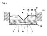
- the support plate 170 has a flat surface allowing the light guider 150 to be placed on the same plane. As shown in Fig. 4 , the support plate 170 is inserted and fixed to the lower part of the opening of the heat radiating body 110. The support plate 170 is disposed under the light guider and supports the light guider. The support plate 170 is made of an optical transmitting material such that light converged by the light guider is emitted to the outside through the support plate.
- Fig. 4 is a view for describing an optical path characteristic of a lamp device in an embodiment of the present invention.
- light emitted from the LEDs 133 travels toward the center of the opening G1 of the ring structure along the inside of the optical prism 150 disposed perpendicular to the inner surface of the ring structure 111. Then, the light is reflected by a reflective material 150a coated on the end surface of the optical prism and is emitted toward the support plate 170.
- the light reflected by the end surface of the optical prism is incident actually perpendicular to the top surface of the support plate 170 contacting with the bottom surface of the optical prism.
- the incident light is emitted to the outside through the support plate made of an optical transmitting material.
- the lower part of the support plate is formed concave toward a side on which light is incident. This intends to obtain a light distribution characteristic when light converged by using the optical prism is emitted to the outside.
- the lamp device mentioned above includes a heat radiating body having a structure in which the heat generated from the light emitting diodes can be radiated spatially not in an up-and-down direction but in a horizontal direction when the lamp device is operated, the entire volume of the lamp device can be actually reduced. Accordingly, as compared with a conventional heat radiating body radiating heat in the up-and-down direction, the heat radiating body of the present invention has a lower spatial limitation when the lamp device is installed. As a result, installation flexibility can be improved.
Landscapes
- Physics & Mathematics (AREA)
- General Physics & Mathematics (AREA)
- Engineering & Computer Science (AREA)
- Optics & Photonics (AREA)
- General Engineering & Computer Science (AREA)
- Microelectronics & Electronic Packaging (AREA)
- Non-Portable Lighting Devices Or Systems Thereof (AREA)
- Arrangement Of Elements, Cooling, Sealing, Or The Like Of Lighting Devices (AREA)
Claims (14)
- Lampenvorrichtung, die Folgendes umfasst:eine Struktur (111), die eine Öffnung (G1) und eine Innenfläche umfasst, die die Öffnung (G1) bildet;mehrere lichtemittierende Vorrichtungen (130), die auf der Innenfläche der Struktur angeordnet sind;mehrere optische Prismen (150), die in einer Richtung angeordnet sind, die senkrecht zur Innenfläche der Struktur (111) ist, und optisch mit der lichtemittierenden Vorrichtung (130) verbunden sind; undeine Tragplatte (170), die auf lichtemittierenden Flächen der optischen Prismen (150) angeordnet ist, an die Struktur (111) gekoppelt ist und die optischen Prismen (150) trägt;wobei die optischen Prismen (150) eine Endfläche umfassen und die Endfläche mit einem reflektierenden Material (150a) beschichtet ist; undwobei der untere Teil der Tragplatte (170) konkav in Richtung einer Seite gebildet ist, auf die Licht einfällt.
- Lampenvorrichtung nach Anspruch 1, wobei die Struktur (111) eine Ringform aufweist.
- Lampenvorrichtung nach Anspruch 1, wobei die Innenfläche der Struktur (111) mehrere flache Abschnitte (115) umfasst und wobei die lichtemittierenden Vorrichtungen (130) auf den flachen Abschnitten (115) angeordnet sind.
- Lampenvorrichtung nach Anspruch 3, wobei mindestens zwei flache Abschnitte der flachen Abschnitte (115) im Wesentlichen parallel zueinander sind und einander gegenüberstehen.
- Lampenvorrichtung nach Anspruch 1 oder Anspruch 2, wobei die Struktur (111) mehrere Rippen (113) zum Abstrahlen von Wärme umfasst, die von den lichtemittierenden Vorrichtungen (130) erzeugt wird, und wobei die Rippen (113) mit einer Außenfläche der Struktur (111) verbunden sind und sich radial erstrecken.
- Lampenvorrichtung nach Anspruch 1, wobei die optischen Prismen (150) sich in der Form einer viereckigen Säule von den lichtemittierenden Vorrichtungen (130) in Richtung der Mittelachse (A) der Öffnung (G1) der Struktur (111) erstrecken, wobei die Endfläche der viereckigen Säule in einem stumpfen Winkel im Bezug zur oberen Fläche der viereckigen Säule geneigt ist und wobei die Endfläche der viereckigen Säule mit dem reflektierenden Material (150a) beschichtet ist.
- Lampenvorrichtung nach Anspruch 6, wobei Enden benachbarter optischer Prismen (150) miteinander in Berührung stehen, derart, dass durch die Enden der optischen Prismen (150) im Wesentlichen eine geschlossene Kurve gebildet wird.
- Lampenvorrichtung nach Anspruch 1 oder Anspruch 6 bis 7, wobei die optischen Prismen (150) im Bezug zur Tragplatte (170) radial angeordnet sind.
- Lampenvorrichtung nach Anspruch 1, wobei Licht, das von den lichtemittierenden Vorrichtungen (130) emittiert wird, im Wesentlichen in eine Richtung reflektiert wird, die von der Endfläche des optischen Prismas (150) im Wesentlichen senkrecht zur unteren Fläche des optischen Prismas (150) ist.
- Lampenvorrichtung nach Anspruch 1, wobei die Tragplatte (170) aus einem optisch durchlässigen Material hergestellt ist.
- Lampenvorrichtung nach Anspruch 1 oder Anspruch 6, wobei die lichtemittierenden Flächen der optischen Prismen (150) auf derselben Ebene liegen.
- Lampenvorrichtung nach Anspruch 1 oder Anspruch 8, wobei die Tragplatte (170) in den unteren Teil der Öffnung (G1) der Struktur (111) eingesetzt ist.
- Lampenvorrichtung nach Anspruch 1, wobei die lichtemittierenden Vorrichtungen (130) radial mit einem gleichen Abstand auf der Innenfläche der Struktur (111) angeordnet sind.
- Lampenvorrichtung nach Anspruch 1 oder Anspruch 8, wobei zwischen den lichtemittierenden Vorrichtungen (130) und der Innenfläche der Struktur (111) eine leitende Folie angeordnet ist.
Applications Claiming Priority (1)
| Application Number | Priority Date | Filing Date | Title |
|---|---|---|---|
| KR1020100079812A KR101772628B1 (ko) | 2010-08-18 | 2010-08-18 | 램프 장치 |
Publications (2)
| Publication Number | Publication Date |
|---|---|
| EP2420719A1 EP2420719A1 (de) | 2012-02-22 |
| EP2420719B1 true EP2420719B1 (de) | 2013-07-24 |
Family
ID=44279770
Family Applications (1)
| Application Number | Title | Priority Date | Filing Date |
|---|---|---|---|
| EP11153749.4A Not-in-force EP2420719B1 (de) | 2010-08-18 | 2011-02-08 | Lampenvorrichtung mit Leuchtdioden auf einer ringförmigen Fläche und mit Prismen |
Country Status (4)
| Country | Link |
|---|---|
| US (1) | US8083375B2 (de) |
| EP (1) | EP2420719B1 (de) |
| KR (1) | KR101772628B1 (de) |
| CN (1) | CN102374421B (de) |
Families Citing this family (33)
| Publication number | Priority date | Publication date | Assignee | Title |
|---|---|---|---|---|
| USD671257S1 (en) * | 2010-04-10 | 2012-11-20 | Lg Innotek Co., Ltd. | LED lamp |
| KR101772644B1 (ko) * | 2010-08-11 | 2017-08-29 | 엘지이노텍 주식회사 | 조명 장치 |
| DE102012200416B4 (de) | 2012-01-12 | 2018-03-01 | Osram Opto Semiconductors Gmbh | Optoelektronisches modul und verfahren zur herstellung eines optoelektronischen moduls |
| US8926158B2 (en) | 2012-04-30 | 2015-01-06 | Qualcomm Mems Technologies, Inc. | Array illumination system |
| US8534875B1 (en) * | 2012-05-03 | 2013-09-17 | Shiyong Zhang | Customizable heat sink formed of sheet material for a lamp |
| CN102722077A (zh) * | 2012-05-24 | 2012-10-10 | 深圳市绎立锐光科技开发有限公司 | 光源系统及相关投影系统 |
| US20130329451A1 (en) * | 2012-06-11 | 2013-12-12 | Falcon Lin | Surgical light with led light guiding and focusing structure and method |
| TW201414957A (zh) * | 2012-10-02 | 2014-04-16 | Wintek Corp | 照明裝置 |
| TWD157914S (zh) * | 2013-02-01 | 2013-12-11 | 璨圓光電股份有限公司 | 發光裝置之部分 |
| TWD157917S (zh) * | 2013-02-01 | 2013-12-11 | 璨圓光電股份有限公司 | 發光裝置之基板之部分 |
| TWD157913S (zh) * | 2013-02-01 | 2013-12-11 | 璨圓光電股份有限公司 | 發光裝置之部分 |
| TWD157911S (zh) * | 2013-02-01 | 2013-12-11 | 璨圓光電股份有限公司 | 發光裝置之部分 |
| TWD157912S (zh) * | 2013-02-01 | 2013-12-11 | 璨圓光電股份有限公司 | 發光裝置之部分 |
| TWD156621S (zh) * | 2013-02-01 | 2013-10-21 | 璨圓光電股份有限公司 | 發光裝置之部分 |
| CN104180216B (zh) * | 2013-05-28 | 2016-08-10 | 赛尔富电子有限公司 | 一种面发光模组 |
| CN103322471A (zh) * | 2013-05-29 | 2013-09-25 | 芜湖雅图数字视频技术有限公司 | 一种投影仪led光源结构 |
| USD719109S1 (en) * | 2013-09-18 | 2014-12-09 | Lediamond Opto Corporation | LED structure |
| US20150098217A1 (en) * | 2013-10-04 | 2015-04-09 | Deran Stinson Eaton | Color Blending System and Method |
| USD719110S1 (en) * | 2013-10-04 | 2014-12-09 | Lediamond Opto Corporation | LED structure |
| US9052418B2 (en) * | 2013-10-08 | 2015-06-09 | Industrial Technology Research Institute | Light source module |
| USD748297S1 (en) * | 2013-12-02 | 2016-01-26 | Bonshine Optical Electron Technology Co., Ltd. | LED bulb |
| CN103727433B (zh) * | 2013-12-20 | 2016-07-06 | 广州市雅江光电设备有限公司 | 一种led环式棱镜光源 |
| CN104214743B (zh) * | 2014-08-29 | 2017-01-25 | 苏州骏发精密机械有限公司 | 格栅型led散热器 |
| CN104214748B (zh) * | 2014-09-01 | 2017-03-15 | 石狮市鹏工汽车教学设备有限公司 | 格栅型汽车前照灯散热器 |
| FR3034169B1 (fr) * | 2015-03-23 | 2020-05-29 | Valeo Iluminacion | Module lumineux pour vehicule automobile comprenant deux guides de lumiere et un radiateur comprenant deux faces de montage |
| CN206130886U (zh) * | 2016-10-25 | 2017-04-26 | 深圳市大疆创新科技有限公司 | 一种灯罩、灯具及飞行器 |
| CN108613099B (zh) * | 2016-12-16 | 2024-02-23 | 市光法雷奥(佛山)汽车照明系统有限公司 | 用于机动车辆的多功能发光装置 |
| US10690312B2 (en) | 2017-05-18 | 2020-06-23 | Tri Lite, Inc. | Light emitting diode signal light |
| DE102019206757A1 (de) * | 2019-05-10 | 2020-11-12 | Robert Bosch Gmbh | Strahlformungseinheit für ein Lichtquellenmodul, Lichtquellenmodul, elektronisches Gerät und Verfahren zum Herstellen einer Strahlformungseinheit für ein Lichtquellenmodul |
| JP7518375B2 (ja) * | 2020-09-30 | 2024-07-18 | 日亜化学工業株式会社 | 発光装置 |
| JP2023016087A (ja) * | 2021-07-21 | 2023-02-02 | 株式会社ジャパンディスプレイ | 照明装置 |
| CN117806106A (zh) * | 2022-09-26 | 2024-04-02 | 中强光电股份有限公司 | 光源组件及投影装置 |
| KR20250068803A (ko) | 2023-11-09 | 2025-05-19 | 장종환 | 광치료용 바이오 캡슐, 이를 위한 의료 시스템과 처방 유통 시스템, 및 이를 이용한 비-인간 동물의 치료방법 |
Family Cites Families (16)
| Publication number | Priority date | Publication date | Assignee | Title |
|---|---|---|---|---|
| JP3118503B2 (ja) * | 1996-07-08 | 2000-12-18 | シーシーエス株式会社 | 照明装置 |
| US6443582B1 (en) * | 2000-08-30 | 2002-09-03 | Visteon Corporation | Edge-lit light assembly with light guiding structures |
| JP3496644B2 (ja) * | 2001-01-12 | 2004-02-16 | シーシーエス株式会社 | 検査用照明装置 |
| JP3989412B2 (ja) * | 2002-10-21 | 2007-10-10 | オリンパス株式会社 | 照明装置及び画像投影装置 |
| ITFI20030099A1 (it) * | 2003-04-08 | 2004-10-09 | Elettromeccanica Cm S R L | Apparecchiatura per la segnalazione luminosa |
| US7237927B2 (en) * | 2004-06-17 | 2007-07-03 | Osram Sylvania Inc. | Light emitting diode lamp with conically focused light guides |
| JP2006040861A (ja) * | 2004-06-25 | 2006-02-09 | Olympus Corp | 照明デバイス、照明装置、及び、画像投影装置 |
| CN1752513A (zh) * | 2004-09-22 | 2006-03-29 | 奥斯兰姆施尔凡尼亚公司 | 发光二极管前灯 |
| US7261452B2 (en) * | 2004-09-22 | 2007-08-28 | Osram Sylvania Inc. | LED headlight |
| CN101213482A (zh) * | 2005-05-09 | 2008-07-02 | Seo精密公司 | 全向灯 |
| DE102005030374A1 (de) * | 2005-06-29 | 2007-01-04 | Zumtobel Staff Gmbh | Leuchte mit einer Vielzahl von Leuchtdioden in dezentraler Anordnung |
| US7506985B2 (en) * | 2005-10-26 | 2009-03-24 | Hewlett-Packard Development Company, L.P. | Projection light source having multiple light emitting diodes |
| WO2008047851A1 (en) * | 2006-10-12 | 2008-04-24 | Panasonic Corporation | Light-emitting apparatus |
| DE102006048571A1 (de) * | 2006-10-13 | 2008-04-17 | Gnisa, Frank, Dipl.-Ing. | Lumenstarke energiesparende Lichtquelle |
| US20080186734A1 (en) * | 2007-02-02 | 2008-08-07 | Kong Kong Applied Science And Technology Research Institute Co., Ltd. | Side-emitting backlight system and backlit display using the same |
| JP2008270066A (ja) * | 2007-04-24 | 2008-11-06 | Olympus Corp | 照明装置およびプロジェクタ |
-
2010
- 2010-08-18 KR KR1020100079812A patent/KR101772628B1/ko not_active Expired - Fee Related
-
2011
- 2011-02-08 EP EP11153749.4A patent/EP2420719B1/de not_active Not-in-force
- 2011-03-04 US US13/040,470 patent/US8083375B2/en not_active Expired - Fee Related
- 2011-03-09 CN CN201110059454.2A patent/CN102374421B/zh not_active Expired - Fee Related
Also Published As
| Publication number | Publication date |
|---|---|
| US20110205737A1 (en) | 2011-08-25 |
| KR20120017234A (ko) | 2012-02-28 |
| KR101772628B1 (ko) | 2017-08-29 |
| CN102374421B (zh) | 2014-04-02 |
| US8083375B2 (en) | 2011-12-27 |
| CN102374421A (zh) | 2012-03-14 |
| EP2420719A1 (de) | 2012-02-22 |
Similar Documents
| Publication | Publication Date | Title |
|---|---|---|
| US8083375B2 (en) | Lamp device | |
| CN102844620B (zh) | 面照明器具和面照明装置 | |
| CN102472860B (zh) | 自由形式照明模块 | |
| EP2829792B1 (de) | Beleuchtungsvorrichtung | |
| US9353931B2 (en) | Lighting device | |
| JP2013038078A (ja) | Led照明灯具 | |
| US20120195039A1 (en) | Lamp device | |
| TW201408952A (zh) | 低剖面發光二極體熱管理系統 | |
| EP2880484A1 (de) | Omnidirektionaler reflektor mit kegelstumpfförmiger oberfläche für eine leuchtdiode | |
| EP2431660B1 (de) | Lampenvorrichtung | |
| JP2013182730A (ja) | 照明モジュールおよびそれを備えた照明装置 | |
| WO2013128761A1 (ja) | 照明モジュールおよびそれを備えた照明装置 | |
| US9476571B2 (en) | Lighting apparatus | |
| JP2012175013A (ja) | 発光装置および照明器具 | |
| KR102523189B1 (ko) | 조명장치 | |
| KR101063955B1 (ko) | 엘이디 조명패널 | |
| JP2016162685A (ja) | レンズ、レンズユニット及び照明器具 | |
| JP5528530B2 (ja) | 照明装置 | |
| EP3492802B1 (de) | Led-beleuchtungsvorrichtung | |
| JP2013098083A (ja) | 照明器具 | |
| JP2022159472A (ja) | Led照明器具 | |
| EP3225904B1 (de) | Beleuchtungsmodul und leuchte | |
| JP6055299B2 (ja) | 照明器具 | |
| CN204648029U (zh) | Led照明装置 | |
| KR101219020B1 (ko) | 실린더 렌즈가 구비된 엘이디 형광등 |
Legal Events
| Date | Code | Title | Description |
|---|---|---|---|
| 17P | Request for examination filed |
Effective date: 20110502 |
|
| AK | Designated contracting states |
Kind code of ref document: A1 Designated state(s): AL AT BE BG CH CY CZ DE DK EE ES FI FR GB GR HR HU IE IS IT LI LT LU LV MC MK MT NL NO PL PT RO RS SE SI SK SM TR |
|
| AX | Request for extension of the european patent |
Extension state: BA ME |
|
| PUAI | Public reference made under article 153(3) epc to a published international application that has entered the european phase |
Free format text: ORIGINAL CODE: 0009012 |
|
| GRAP | Despatch of communication of intention to grant a patent |
Free format text: ORIGINAL CODE: EPIDOSNIGR1 |
|
| GRAS | Grant fee paid |
Free format text: ORIGINAL CODE: EPIDOSNIGR3 |
|
| GRAA | (expected) grant |
Free format text: ORIGINAL CODE: 0009210 |
|
| AK | Designated contracting states |
Kind code of ref document: B1 Designated state(s): AL AT BE BG CH CY CZ DE DK EE ES FI FR GB GR HR HU IE IS IT LI LT LU LV MC MK MT NL NO PL PT RO RS SE SI SK SM TR |
|
| REG | Reference to a national code |
Ref country code: GB Ref legal event code: FG4D |
|
| REG | Reference to a national code |
Ref country code: CH Ref legal event code: EP |
|
| REG | Reference to a national code |
Ref country code: AT Ref legal event code: REF Ref document number: 623666 Country of ref document: AT Kind code of ref document: T Effective date: 20130815 |
|
| REG | Reference to a national code |
Ref country code: IE Ref legal event code: FG4D |
|
| REG | Reference to a national code |
Ref country code: NL Ref legal event code: T3 |
|
| REG | Reference to a national code |
Ref country code: DE Ref legal event code: R096 Ref document number: 602011002410 Country of ref document: DE Effective date: 20130926 |
|
| REG | Reference to a national code |
Ref country code: AT Ref legal event code: MK05 Ref document number: 623666 Country of ref document: AT Kind code of ref document: T Effective date: 20130724 |
|
| REG | Reference to a national code |
Ref country code: LT Ref legal event code: MG4D |
|
| PG25 | Lapsed in a contracting state [announced via postgrant information from national office to epo] |
Ref country code: HR Free format text: LAPSE BECAUSE OF FAILURE TO SUBMIT A TRANSLATION OF THE DESCRIPTION OR TO PAY THE FEE WITHIN THE PRESCRIBED TIME-LIMIT Effective date: 20130724 Ref country code: BE Free format text: LAPSE BECAUSE OF FAILURE TO SUBMIT A TRANSLATION OF THE DESCRIPTION OR TO PAY THE FEE WITHIN THE PRESCRIBED TIME-LIMIT Effective date: 20130724 Ref country code: PT Free format text: LAPSE BECAUSE OF FAILURE TO SUBMIT A TRANSLATION OF THE DESCRIPTION OR TO PAY THE FEE WITHIN THE PRESCRIBED TIME-LIMIT Effective date: 20131125 Ref country code: AT Free format text: LAPSE BECAUSE OF FAILURE TO SUBMIT A TRANSLATION OF THE DESCRIPTION OR TO PAY THE FEE WITHIN THE PRESCRIBED TIME-LIMIT Effective date: 20130724 Ref country code: LT Free format text: LAPSE BECAUSE OF FAILURE TO SUBMIT A TRANSLATION OF THE DESCRIPTION OR TO PAY THE FEE WITHIN THE PRESCRIBED TIME-LIMIT Effective date: 20130724 Ref country code: CY Free format text: LAPSE BECAUSE OF FAILURE TO SUBMIT A TRANSLATION OF THE DESCRIPTION OR TO PAY THE FEE WITHIN THE PRESCRIBED TIME-LIMIT Effective date: 20130814 Ref country code: SE Free format text: LAPSE BECAUSE OF FAILURE TO SUBMIT A TRANSLATION OF THE DESCRIPTION OR TO PAY THE FEE WITHIN THE PRESCRIBED TIME-LIMIT Effective date: 20130724 Ref country code: NO Free format text: LAPSE BECAUSE OF FAILURE TO SUBMIT A TRANSLATION OF THE DESCRIPTION OR TO PAY THE FEE WITHIN THE PRESCRIBED TIME-LIMIT Effective date: 20131024 Ref country code: IS Free format text: LAPSE BECAUSE OF FAILURE TO SUBMIT A TRANSLATION OF THE DESCRIPTION OR TO PAY THE FEE WITHIN THE PRESCRIBED TIME-LIMIT Effective date: 20131124 |
|
| PG25 | Lapsed in a contracting state [announced via postgrant information from national office to epo] |
Ref country code: GR Free format text: LAPSE BECAUSE OF FAILURE TO SUBMIT A TRANSLATION OF THE DESCRIPTION OR TO PAY THE FEE WITHIN THE PRESCRIBED TIME-LIMIT Effective date: 20131025 Ref country code: PL Free format text: LAPSE BECAUSE OF FAILURE TO SUBMIT A TRANSLATION OF THE DESCRIPTION OR TO PAY THE FEE WITHIN THE PRESCRIBED TIME-LIMIT Effective date: 20130724 Ref country code: SI Free format text: LAPSE BECAUSE OF FAILURE TO SUBMIT A TRANSLATION OF THE DESCRIPTION OR TO PAY THE FEE WITHIN THE PRESCRIBED TIME-LIMIT Effective date: 20130724 Ref country code: FI Free format text: LAPSE BECAUSE OF FAILURE TO SUBMIT A TRANSLATION OF THE DESCRIPTION OR TO PAY THE FEE WITHIN THE PRESCRIBED TIME-LIMIT Effective date: 20130724 Ref country code: LV Free format text: LAPSE BECAUSE OF FAILURE TO SUBMIT A TRANSLATION OF THE DESCRIPTION OR TO PAY THE FEE WITHIN THE PRESCRIBED TIME-LIMIT Effective date: 20130724 |
|
| PG25 | Lapsed in a contracting state [announced via postgrant information from national office to epo] |
Ref country code: CY Free format text: LAPSE BECAUSE OF FAILURE TO SUBMIT A TRANSLATION OF THE DESCRIPTION OR TO PAY THE FEE WITHIN THE PRESCRIBED TIME-LIMIT Effective date: 20130724 |
|
| PG25 | Lapsed in a contracting state [announced via postgrant information from national office to epo] |
Ref country code: SK Free format text: LAPSE BECAUSE OF FAILURE TO SUBMIT A TRANSLATION OF THE DESCRIPTION OR TO PAY THE FEE WITHIN THE PRESCRIBED TIME-LIMIT Effective date: 20130724 Ref country code: EE Free format text: LAPSE BECAUSE OF FAILURE TO SUBMIT A TRANSLATION OF THE DESCRIPTION OR TO PAY THE FEE WITHIN THE PRESCRIBED TIME-LIMIT Effective date: 20130724 Ref country code: DK Free format text: LAPSE BECAUSE OF FAILURE TO SUBMIT A TRANSLATION OF THE DESCRIPTION OR TO PAY THE FEE WITHIN THE PRESCRIBED TIME-LIMIT Effective date: 20130724 Ref country code: RO Free format text: LAPSE BECAUSE OF FAILURE TO SUBMIT A TRANSLATION OF THE DESCRIPTION OR TO PAY THE FEE WITHIN THE PRESCRIBED TIME-LIMIT Effective date: 20130724 Ref country code: CZ Free format text: LAPSE BECAUSE OF FAILURE TO SUBMIT A TRANSLATION OF THE DESCRIPTION OR TO PAY THE FEE WITHIN THE PRESCRIBED TIME-LIMIT Effective date: 20130724 |
|
| PG25 | Lapsed in a contracting state [announced via postgrant information from national office to epo] |
Ref country code: ES Free format text: LAPSE BECAUSE OF FAILURE TO SUBMIT A TRANSLATION OF THE DESCRIPTION OR TO PAY THE FEE WITHIN THE PRESCRIBED TIME-LIMIT Effective date: 20130724 Ref country code: IT Free format text: LAPSE BECAUSE OF FAILURE TO SUBMIT A TRANSLATION OF THE DESCRIPTION OR TO PAY THE FEE WITHIN THE PRESCRIBED TIME-LIMIT Effective date: 20130724 |
|
| PLBE | No opposition filed within time limit |
Free format text: ORIGINAL CODE: 0009261 |
|
| STAA | Information on the status of an ep patent application or granted ep patent |
Free format text: STATUS: NO OPPOSITION FILED WITHIN TIME LIMIT |
|
| 26N | No opposition filed |
Effective date: 20140425 |
|
| REG | Reference to a national code |
Ref country code: DE Ref legal event code: R097 Ref document number: 602011002410 Country of ref document: DE Effective date: 20140425 |
|
| PG25 | Lapsed in a contracting state [announced via postgrant information from national office to epo] |
Ref country code: LU Free format text: LAPSE BECAUSE OF FAILURE TO SUBMIT A TRANSLATION OF THE DESCRIPTION OR TO PAY THE FEE WITHIN THE PRESCRIBED TIME-LIMIT Effective date: 20140208 Ref country code: MC Free format text: LAPSE BECAUSE OF FAILURE TO SUBMIT A TRANSLATION OF THE DESCRIPTION OR TO PAY THE FEE WITHIN THE PRESCRIBED TIME-LIMIT Effective date: 20130724 |
|
| REG | Reference to a national code |
Ref country code: CH Ref legal event code: PL |
|
| PG25 | Lapsed in a contracting state [announced via postgrant information from national office to epo] |
Ref country code: CH Free format text: LAPSE BECAUSE OF NON-PAYMENT OF DUE FEES Effective date: 20140228 Ref country code: LI Free format text: LAPSE BECAUSE OF NON-PAYMENT OF DUE FEES Effective date: 20140228 |
|
| REG | Reference to a national code |
Ref country code: FR Ref legal event code: ST Effective date: 20141031 |
|
| REG | Reference to a national code |
Ref country code: IE Ref legal event code: MM4A |
|
| PG25 | Lapsed in a contracting state [announced via postgrant information from national office to epo] |
Ref country code: IE Free format text: LAPSE BECAUSE OF NON-PAYMENT OF DUE FEES Effective date: 20140208 Ref country code: FR Free format text: LAPSE BECAUSE OF NON-PAYMENT OF DUE FEES Effective date: 20140228 |
|
| PG25 | Lapsed in a contracting state [announced via postgrant information from national office to epo] |
Ref country code: MT Free format text: LAPSE BECAUSE OF FAILURE TO SUBMIT A TRANSLATION OF THE DESCRIPTION OR TO PAY THE FEE WITHIN THE PRESCRIBED TIME-LIMIT Effective date: 20130724 |
|
| PG25 | Lapsed in a contracting state [announced via postgrant information from national office to epo] |
Ref country code: SM Free format text: LAPSE BECAUSE OF FAILURE TO SUBMIT A TRANSLATION OF THE DESCRIPTION OR TO PAY THE FEE WITHIN THE PRESCRIBED TIME-LIMIT Effective date: 20130724 |
|
| PG25 | Lapsed in a contracting state [announced via postgrant information from national office to epo] |
Ref country code: BG Free format text: LAPSE BECAUSE OF FAILURE TO SUBMIT A TRANSLATION OF THE DESCRIPTION OR TO PAY THE FEE WITHIN THE PRESCRIBED TIME-LIMIT Effective date: 20130724 Ref country code: RS Free format text: LAPSE BECAUSE OF FAILURE TO SUBMIT A TRANSLATION OF THE DESCRIPTION OR TO PAY THE FEE WITHIN THE PRESCRIBED TIME-LIMIT Effective date: 20130724 |
|
| PG25 | Lapsed in a contracting state [announced via postgrant information from national office to epo] |
Ref country code: TR Free format text: LAPSE BECAUSE OF FAILURE TO SUBMIT A TRANSLATION OF THE DESCRIPTION OR TO PAY THE FEE WITHIN THE PRESCRIBED TIME-LIMIT Effective date: 20130724 Ref country code: HU Free format text: LAPSE BECAUSE OF FAILURE TO SUBMIT A TRANSLATION OF THE DESCRIPTION OR TO PAY THE FEE WITHIN THE PRESCRIBED TIME-LIMIT; INVALID AB INITIO Effective date: 20110208 |
|
| PGFP | Annual fee paid to national office [announced via postgrant information from national office to epo] |
Ref country code: NL Payment date: 20180108 Year of fee payment: 8 |
|
| PG25 | Lapsed in a contracting state [announced via postgrant information from national office to epo] |
Ref country code: MK Free format text: LAPSE BECAUSE OF FAILURE TO SUBMIT A TRANSLATION OF THE DESCRIPTION OR TO PAY THE FEE WITHIN THE PRESCRIBED TIME-LIMIT Effective date: 20130724 |
|
| PG25 | Lapsed in a contracting state [announced via postgrant information from national office to epo] |
Ref country code: AL Free format text: LAPSE BECAUSE OF FAILURE TO SUBMIT A TRANSLATION OF THE DESCRIPTION OR TO PAY THE FEE WITHIN THE PRESCRIBED TIME-LIMIT Effective date: 20130724 |
|
| REG | Reference to a national code |
Ref country code: NL Ref legal event code: MM Effective date: 20190301 |
|
| PG25 | Lapsed in a contracting state [announced via postgrant information from national office to epo] |
Ref country code: NL Free format text: LAPSE BECAUSE OF NON-PAYMENT OF DUE FEES Effective date: 20190301 |
|
| REG | Reference to a national code |
Ref country code: GB Ref legal event code: 732E Free format text: REGISTERED BETWEEN 20210722 AND 20210728 |
|
| REG | Reference to a national code |
Ref country code: DE Ref legal event code: R081 Ref document number: 602011002410 Country of ref document: DE Owner name: SUZHOU LEKIN SEMICONDUCTOR CO. LTD., TAICANG, CN Free format text: FORMER OWNER: LG INNOTEK CO., LTD., SEOUL/SOUL, KR |
|
| PGFP | Annual fee paid to national office [announced via postgrant information from national office to epo] |
Ref country code: GB Payment date: 20230105 Year of fee payment: 13 Ref country code: DE Payment date: 20230104 Year of fee payment: 13 |
|
| REG | Reference to a national code |
Ref country code: DE Ref legal event code: R119 Ref document number: 602011002410 Country of ref document: DE |
|
| GBPC | Gb: european patent ceased through non-payment of renewal fee |
Effective date: 20240208 |
|
| PG25 | Lapsed in a contracting state [announced via postgrant information from national office to epo] |
Ref country code: DE Free format text: LAPSE BECAUSE OF NON-PAYMENT OF DUE FEES Effective date: 20240903 |
|
| PG25 | Lapsed in a contracting state [announced via postgrant information from national office to epo] |
Ref country code: GB Free format text: LAPSE BECAUSE OF NON-PAYMENT OF DUE FEES Effective date: 20240208 |
|
| PG25 | Lapsed in a contracting state [announced via postgrant information from national office to epo] |
Ref country code: GB Free format text: LAPSE BECAUSE OF NON-PAYMENT OF DUE FEES Effective date: 20240208 Ref country code: DE Free format text: LAPSE BECAUSE OF NON-PAYMENT OF DUE FEES Effective date: 20240903 |