EP2419792B1 - Light reactive media and methods of recording visible images - Google Patents
Light reactive media and methods of recording visible images Download PDFInfo
- Publication number
- EP2419792B1 EP2419792B1 EP10724886.6A EP10724886A EP2419792B1 EP 2419792 B1 EP2419792 B1 EP 2419792B1 EP 10724886 A EP10724886 A EP 10724886A EP 2419792 B1 EP2419792 B1 EP 2419792B1
- Authority
- EP
- European Patent Office
- Prior art keywords
- layer
- frequency
- electromagnetic radiation
- medium
- light
- Prior art date
- Legal status (The legal status is an assumption and is not a legal conclusion. Google has not performed a legal analysis and makes no representation as to the accuracy of the status listed.)
- Not-in-force
Links
- 238000000034 method Methods 0.000 title claims description 33
- 230000005670 electromagnetic radiation Effects 0.000 claims description 30
- 230000008859 change Effects 0.000 claims description 18
- 238000009826 distribution Methods 0.000 claims description 6
- 230000004044 response Effects 0.000 claims description 5
- 238000012634 optical imaging Methods 0.000 claims description 3
- 230000002427 irreversible effect Effects 0.000 claims 2
- 239000010410 layer Substances 0.000 description 102
- 239000000463 material Substances 0.000 description 18
- 239000011241 protective layer Substances 0.000 description 17
- 238000010586 diagram Methods 0.000 description 16
- 238000000576 coating method Methods 0.000 description 9
- 238000003384 imaging method Methods 0.000 description 8
- 238000007639 printing Methods 0.000 description 8
- 230000003287 optical effect Effects 0.000 description 6
- 239000011248 coating agent Substances 0.000 description 5
- 230000000694 effects Effects 0.000 description 5
- 238000005286 illumination Methods 0.000 description 5
- 230000008901 benefit Effects 0.000 description 4
- 230000008569 process Effects 0.000 description 4
- 230000002441 reversible effect Effects 0.000 description 4
- 238000006243 chemical reaction Methods 0.000 description 3
- 238000010276 construction Methods 0.000 description 3
- 239000000758 substrate Substances 0.000 description 3
- OAICVXFJPJFONN-UHFFFAOYSA-N Phosphorus Chemical compound [P] OAICVXFJPJFONN-UHFFFAOYSA-N 0.000 description 2
- 230000000903 blocking effect Effects 0.000 description 2
- 239000003086 colorant Substances 0.000 description 2
- 239000000975 dye Substances 0.000 description 2
- 230000006870 function Effects 0.000 description 2
- 238000004806 packaging method and process Methods 0.000 description 2
- 230000001737 promoting effect Effects 0.000 description 2
- 230000005855 radiation Effects 0.000 description 2
- 239000002356 single layer Substances 0.000 description 2
- 230000007704 transition Effects 0.000 description 2
- 230000000007 visual effect Effects 0.000 description 2
- 150000001875 compounds Chemical class 0.000 description 1
- 230000035622 drinking Effects 0.000 description 1
- 230000005611 electricity Effects 0.000 description 1
- 238000005265 energy consumption Methods 0.000 description 1
- 230000001747 exhibiting effect Effects 0.000 description 1
- 239000004744 fabric Substances 0.000 description 1
- 230000001678 irradiating effect Effects 0.000 description 1
- 239000007788 liquid Substances 0.000 description 1
- 238000004519 manufacturing process Methods 0.000 description 1
- 239000011159 matrix material Substances 0.000 description 1
- 230000015654 memory Effects 0.000 description 1
- 238000002156 mixing Methods 0.000 description 1
- 238000007645 offset printing Methods 0.000 description 1
- 239000000123 paper Substances 0.000 description 1
- 239000004033 plastic Substances 0.000 description 1
- 229920003023 plastic Polymers 0.000 description 1
- 238000002360 preparation method Methods 0.000 description 1
- 238000006748 scratching Methods 0.000 description 1
- 230000002393 scratching effect Effects 0.000 description 1
- 238000007650 screen-printing Methods 0.000 description 1
- 239000002023 wood Substances 0.000 description 1
Images


Classifications
-
- G—PHYSICS
- G03—PHOTOGRAPHY; CINEMATOGRAPHY; ANALOGOUS TECHNIQUES USING WAVES OTHER THAN OPTICAL WAVES; ELECTROGRAPHY; HOLOGRAPHY
- G03B—APPARATUS OR ARRANGEMENTS FOR TAKING PHOTOGRAPHS OR FOR PROJECTING OR VIEWING THEM; APPARATUS OR ARRANGEMENTS EMPLOYING ANALOGOUS TECHNIQUES USING WAVES OTHER THAN OPTICAL WAVES; ACCESSORIES THEREFOR
- G03B21/00—Projectors or projection-type viewers; Accessories therefor
- G03B21/54—Accessories
- G03B21/56—Projection screens
- G03B21/60—Projection screens characterised by the nature of the surface
- G03B21/602—Lenticular screens
-
- G—PHYSICS
- G03—PHOTOGRAPHY; CINEMATOGRAPHY; ANALOGOUS TECHNIQUES USING WAVES OTHER THAN OPTICAL WAVES; ELECTROGRAPHY; HOLOGRAPHY
- G03C—PHOTOSENSITIVE MATERIALS FOR PHOTOGRAPHIC PURPOSES; PHOTOGRAPHIC PROCESSES, e.g. CINE, X-RAY, COLOUR, STEREO-PHOTOGRAPHIC PROCESSES; AUXILIARY PROCESSES IN PHOTOGRAPHY
- G03C7/00—Multicolour photographic processes or agents therefor; Regeneration of such processing agents; Photosensitive materials for multicolour processes
- G03C7/14—Additive processes using lenticular screens; Materials therefor; Preparing or processing such materials
-
- G—PHYSICS
- G02—OPTICS
- G02B—OPTICAL ELEMENTS, SYSTEMS OR APPARATUS
- G02B30/00—Optical systems or apparatus for producing three-dimensional [3D] effects, e.g. stereoscopic images
- G02B30/20—Optical systems or apparatus for producing three-dimensional [3D] effects, e.g. stereoscopic images by providing first and second parallax images to an observer's left and right eyes
- G02B30/26—Optical systems or apparatus for producing three-dimensional [3D] effects, e.g. stereoscopic images by providing first and second parallax images to an observer's left and right eyes of the autostereoscopic type
- G02B30/27—Optical systems or apparatus for producing three-dimensional [3D] effects, e.g. stereoscopic images by providing first and second parallax images to an observer's left and right eyes of the autostereoscopic type involving lenticular arrays
-
- G—PHYSICS
- G03—PHOTOGRAPHY; CINEMATOGRAPHY; ANALOGOUS TECHNIQUES USING WAVES OTHER THAN OPTICAL WAVES; ELECTROGRAPHY; HOLOGRAPHY
- G03B—APPARATUS OR ARRANGEMENTS FOR TAKING PHOTOGRAPHS OR FOR PROJECTING OR VIEWING THEM; APPARATUS OR ARRANGEMENTS EMPLOYING ANALOGOUS TECHNIQUES USING WAVES OTHER THAN OPTICAL WAVES; ACCESSORIES THEREFOR
- G03B21/00—Projectors or projection-type viewers; Accessories therefor
- G03B21/54—Accessories
- G03B21/56—Projection screens
- G03B21/60—Projection screens characterised by the nature of the surface
-
- G—PHYSICS
- G03—PHOTOGRAPHY; CINEMATOGRAPHY; ANALOGOUS TECHNIQUES USING WAVES OTHER THAN OPTICAL WAVES; ELECTROGRAPHY; HOLOGRAPHY
- G03B—APPARATUS OR ARRANGEMENTS FOR TAKING PHOTOGRAPHS OR FOR PROJECTING OR VIEWING THEM; APPARATUS OR ARRANGEMENTS EMPLOYING ANALOGOUS TECHNIQUES USING WAVES OTHER THAN OPTICAL WAVES; ACCESSORIES THEREFOR
- G03B25/00—Viewers, other than projection viewers, giving motion-picture effects by persistence of vision, e.g. zoetrope
- G03B25/02—Viewers, other than projection viewers, giving motion-picture effects by persistence of vision, e.g. zoetrope with interposed lenticular or line screen
-
- G—PHYSICS
- G03—PHOTOGRAPHY; CINEMATOGRAPHY; ANALOGOUS TECHNIQUES USING WAVES OTHER THAN OPTICAL WAVES; ELECTROGRAPHY; HOLOGRAPHY
- G03B—APPARATUS OR ARRANGEMENTS FOR TAKING PHOTOGRAPHS OR FOR PROJECTING OR VIEWING THEM; APPARATUS OR ARRANGEMENTS EMPLOYING ANALOGOUS TECHNIQUES USING WAVES OTHER THAN OPTICAL WAVES; ACCESSORIES THEREFOR
- G03B33/00—Colour photography, other than mere exposure or projection of a colour film
- G03B33/10—Simultaneous recording or projection
- G03B33/14—Simultaneous recording or projection using lenticular screens
-
- G—PHYSICS
- G03—PHOTOGRAPHY; CINEMATOGRAPHY; ANALOGOUS TECHNIQUES USING WAVES OTHER THAN OPTICAL WAVES; ELECTROGRAPHY; HOLOGRAPHY
- G03C—PHOTOSENSITIVE MATERIALS FOR PHOTOGRAPHIC PURPOSES; PHOTOGRAPHIC PROCESSES, e.g. CINE, X-RAY, COLOUR, STEREO-PHOTOGRAPHIC PROCESSES; AUXILIARY PROCESSES IN PHOTOGRAPHY
- G03C9/00—Stereo-photographic or similar processes
- G03C9/02—Parallax-stereogram
-
- G—PHYSICS
- G03—PHOTOGRAPHY; CINEMATOGRAPHY; ANALOGOUS TECHNIQUES USING WAVES OTHER THAN OPTICAL WAVES; ELECTROGRAPHY; HOLOGRAPHY
- G03C—PHOTOSENSITIVE MATERIALS FOR PHOTOGRAPHIC PURPOSES; PHOTOGRAPHIC PROCESSES, e.g. CINE, X-RAY, COLOUR, STEREO-PHOTOGRAPHIC PROCESSES; AUXILIARY PROCESSES IN PHOTOGRAPHY
- G03C1/00—Photosensitive materials
- G03C1/685—Compositions containing spiro-condensed pyran compounds or derivatives thereof, as photosensitive substances
-
- G—PHYSICS
- G03—PHOTOGRAPHY; CINEMATOGRAPHY; ANALOGOUS TECHNIQUES USING WAVES OTHER THAN OPTICAL WAVES; ELECTROGRAPHY; HOLOGRAPHY
- G03C—PHOTOSENSITIVE MATERIALS FOR PHOTOGRAPHIC PURPOSES; PHOTOGRAPHIC PROCESSES, e.g. CINE, X-RAY, COLOUR, STEREO-PHOTOGRAPHIC PROCESSES; AUXILIARY PROCESSES IN PHOTOGRAPHY
- G03C1/00—Photosensitive materials
- G03C1/72—Photosensitive compositions not covered by the groups G03C1/005 - G03C1/705
- G03C1/73—Photosensitive compositions not covered by the groups G03C1/005 - G03C1/705 containing organic compounds
- G03C1/732—Leuco dyes
Definitions
- the present invention relates to light reactive media and to methods of writing images to such media.
- the coatings require a large amount of laser energy to produce the chemical reactions that evoke the colour change in the area to be printed.
- CO 2 lasers in excess of 10 Watts are used, which are not only extremely expensive and very large, but are also classified as industrial lasers and therefore subject to rigorous safety standards; this precludes them from being used in a desktop application.
- lenticular printing is generally used for promotional items ranging from product packaging to novelty items like playing cards and drinking cups.
- the process involves using a number of images interlaced together to form a 3D effect and/or movement, when viewed through a sheet of lenses that allows the viewer to view different images with either eye, or when the eyes move relative to the sheet.
- lenticular images There are a number of ways to produce a lenticular image. In some cases the images are printed directly onto the lens sheet using offset printing. Some products are printed using screen printing. It is also possible to use an inkjet or laser printer to produce the interlaced image and then laminate the image with the lenticular sheet. This requires complex preparation and alignment when applying the lens sheet. The complexity of producing lenticular images has prevented mainstream desktop applications.
- US3166420 discloses a medium with two photochromic layers.
- An advantage of this arrangement is that a visible image may be formed on the first layer using light of the first frequency, and the image may then be 'fixed' using light of the second frequency such that subsequent irradiation by the first frequency makes substantially no visible difference to the first layer.
- the first layer may be made sensitive to low levels of radiation at the first frequency, so that low power light sources may be used.
- the further layer may be changeable from being substantially opaque to said first frequency to being substantially transparent to said first frequency, in response to electromagnetic radiation of a third frequency substantially different from the first and second frequencies.
- An advantage of this arrangement is that the first layer is protected from the first frequency until an image is to be written to the first layer, whereupon the medium is exposed to the third frequency, prior to writing using the first frequency.
- the further layer may comprise a second layer changeable from being substantially transparent to said first frequency to being substantially opaque to said first frequency, in response to said second frequency.
- the further layer may comprise a third layer changeable from being substantially opaque to said first frequency to being substantially transparent to said first frequency, in response to said third frequency.
- the second layer may be disposed between the third layer and the first layer, and the third layer may become transparent to the second frequency, in response to the third frequency.
- the layers may comprise respective different photoreactive or photochromic compounds, such as leuco dyes.
- a method of writing a visible image to the medium comprising exposing the first layer to electromagnetic radiation of the first frequency so as to produce the visible image in the first layer.
- the further layer may subsequently be exposed to electromagnetic radiation of the second frequency such that the further layer becomes substantially opaque to electromagnetic radiation of the first frequency.
- the further layer Prior to the step of exposing the first layer to electromagnetic radiation of the first frequency, the further layer may be exposed to electromagnetic radiation of the third frequency such that the further layer becomes substantially transparent to electromagnetic radiation of the first frequency.
- a method of writing a visible image to a medium comprising a first layer reactive to electromagnetic radiation of a first frequency to exhibit a visible change
- the method comprising exposing the first layer to electromagnetic radiation of the first frequency, and subsequently applying a protective layer over the first layer, the protective layer blocking electromagnetic radiation of said first frequency from acting on the first layer, the visible change being visible through the further layer.
- the protective layer may be arranged to produce a visual effect when the image written to the first layer is viewed therethrough.
- the spatial distribution and/or intensity of the electromagnetic radiation of the first frequency may be controlled so as to create a visible image in the first layer.
- the spatial distribution may be controlled by means of a spatially variant shutter or an optical imaging apparatus, or by scanning a beam of electromagnetic radiation of the first frequency across the medium.
- a method of producing a lenticular image in which a light sensitive medium is provided with a lenticular layer, and multiple images are written at different angles onto the medium through the lenticular layer.
- the multiple images are automatically aligned with the lenses on the lenticular layer, so that the different images are viewable at different angles through the lenticular layer.
- direct energy imaging systems such as the one described in this document will enable the production of blank ready to print lenticular sheets and the development of devices that are capable of taking standard photos and turning them into vibrant 3D and animated media memories, promotional goods and technical photographic illustrations.
- a photoluminescent display comprising an array of pixels each comprising a plurality of phosphorescent elements arranged to emit visible light of a respective different colour when excited by incident light of a predetermined frequency.
- the display may include a microlens array layer comprising a plurality of microlenses, each arranged to direct the incident light onto a corresponding one of the phosphorescent elements.
- the display may include an array of lenses arranged to direct light emitted from respective ones of the pixels.
- the pixels may be arranged in a plurality of groups of said phosphorescent elements, each of said groups is arranged to be visible at a different angle through a corresponding one of the array of lenses, for example to produce a stereoscopic display.
- the method described above does not require a backlight and does not require high-powered laser systems such as laser TV.
- This method of creating a picture can be used to produce images with long phosphorescing time to provide fixed rewritable images, or short phosphorescing times rapid changes in the image.
- the incident light may be generated by heterodyning two or more beams to generate light of the required frequency.
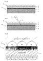
- a photoreactive medium 10 comprises a substrate 4, of flexible or rigid material.
- the substrate may be of plastics, paper, wood or fabric, for example.
- a first layer 1 is applied to the substrate, comprising a material reactive to light at a first frequency f1 to exhibit a visible change, such as a change in colour or shade.
- the first layer 1 may comprise a plurality of materials that each exhibit a different colour change, either arranged in a spatially distinct pattern, or sensitive to different frequencies within the range of frequency f1, to enable colour imaging.
- a second layer 2 is applied over the imaging layer, comprising a material that allows frequency f1 to pass through until exposed to a light of a second frequency f2, whereupon the material changes state so as to block frequency f1.
- a third layer 3 is applied over the first protective layer 3, comprising a material that blocks frequency f1 until exposed to light of a third frequency f3, whereupon the material changes state so as to allow light of the first or second frequency to pass through the third layer 3.
- the frequencies f1 , f2 and f3 are preferably discrete and spaced apart from one another in frequency.
- the light reactive material of the first layer 1 is sensitive to ultraviolet light, so that frequency f1 is in the range 200 to 450 nm, while the light reactive materials of the second and third layers 2, 3 are in the near infrared and infrared ranges, such as between 900 and 1700 nm.
- Each frequency f1, f2, f3 may be monochromatic or polychromatic, with a narrow or broad bandwidth.
- the light reactive materials of the first, second and/or third layers 1, 2, 3 preferably change state, as described above, irreversibly and are therefore photoreactive.
- the change of state may be reversible, in which case the material is photochromic.
- Suitable materials include leuco dyes, which may be encapsulated within a matrix.
- the layers 1, 2 and/or 3 may be applied as liquid coatings that are dried to form the respective layers, or may be preformed and bonded together.
- Imaging apparatus comprises a first light source 5 for generating light of frequency f1, a second light source 6 for generating light of frequency f2, and a third light source 7 for generating light of frequency f3.
- the light sources may be laser diodes or LEDs, for example.
- the use of laser light is preferred at least for frequency f1, because the narrow divergence characteristics facilitate accurate, high-quality writing.
- the third layer 3 is opaque to frequency f1, so that light from the first light source 5 is reflected and/or absorbed by the third layer 3 and does not reach the first layer 1, which is therefore protected from writing.
- the area A to be written is irradiated with light of frequency f3, from the third light source 7; this changes the state of the third layer 3 so as to allow frequency f1 to pass through.
- light of frequency f1 from the first light source 5 is irradiated onto the first layer 1, passing through the second and third layers 2,3, to change the visible state of the first layer 1 in the area A.
- the image in the area A may be controlled by scanning and/or varying the intensity of the light from the first light source 5.
- the exposure of the first layer 1 to frequency f1 may be controlled by varying the output of the first light source 1 and/or using a shutter between the first light source 1 and the medium 10.
- the shutter may comprise a controllable spatially variant shutter such as an LCD panel 8 having a pixel arrangement, each pixel acting as a shutter to control the amount of light reaching a corresponding pixel area of the first layer 1, and hence the degree of colour or shade exhibited by that area.
- Each pixel may be a binary pixel, in which case the time of exposure is controlled, or a variable transparency pixel, in which case the amount may be controlled by the transparency.
- the first layer 1 may be illuminated in turn with the different frequencies, and the LCD panel 8 is controlled to determine the illumination of each pixel area by the corresponding frequency.
- This method is analogous to multi-colour lithographic printing, with the LCD panel 8 acting as a digital printing plate to transfer each colour to the medium 10 in turn.
- the LCD panel 8 may have a pixel pattern corresponding to the spatially distinct pattern, so that illumination of each material is controllable independently.
- a photographic image is written to the first layer at the frequency f1, using an optical imaging system such as a lens for focussing the image on the first layer 1, prior to fixing with uniform illumination by the frequency f2.
- the first, second and third light sources 5, 6, 7 are housed in a print head that is scanned across the medium 10 and arranged in such a way that light from the third, first and second light sources 7, 5, 6 falls onto an area in succession.
- beams from the first, second and third light sources may be scanned across the medium 10 by optical means, such as reflective or refractive parts.
- Light of the second and third frequencies may be scanned across the medium 10, respectively after and before writing of the scanned area by the first frequency.
- the medium 10 may be prepared for writing by substantially uniform illumination by frequency f3.
- the image may be fixed by substantially uniform illumination by frequency f2.
- the third layer 3 is omitted and other means are employed to prevent light of frequency f1 from reaching the first layer 1 before an image is to be written.
- the medium 10 may be kept in an environment that is substantially free of light of frequency f1, or may be covered by a removable protective layer that is opaque to frequency f1.
- a single layer performs the functions of the second and third layers 2, 3 in the first embodiment.
- the single layer contains a photochromic material that is reversible between a first state in which the material is opaque to the frequency f1 and a second state in which the material is transparent to the frequency f1.
- the transition from the first to the second state is activated by light of frequency f3, while the transition from the second to the first state is activated by light of the frequency f2. Since the change is reversible, further images may be written to the first layer after the initial writing step.
- the change of state that produces a visible image in the first layer may also be reversible, so that the image may be erased and a new image rewritten in the first layer.
- a removable and replaceable protective layer 9 is provides over the first layer 1, instead of the second and third layers 2, 3.
- the protective layer 9 comprises a material that is substantially opaque to frequency f1, and is not photoreactive or photochromic.
- the protective layer 9 is preferably flexible.
- the medium 10 is supplied for printing with the protective layer 9 applied.
- the protective layer 9 is physically removed, either manually or by means within the printing apparatus, such as a roller 11. Printing is performed using the first light source 5; the second and third light sources 6, 7 are not necessary in this embodiment.
- the protective layer 9 is then reapplied and permanently bonded to the first layer 1, for example using the roller 11 within the printing apparatus.
- the reapplied protective layer 9 need not be the same protective layer 9 that was previously removed.
- the reapplied protective layer 9 may be arranged to produce a visual effect when the printed first layer 1 is viewed therethrough; for example, the protective layer 9 may comprise lenticular elements arranged to produce a multiple view image, such as a moving sequence of images or a 3D effect.
- a lenticular imaging medium 10 includes a lenticular layer 9, comprising an array of lenses.
- the lenticular layer 9 may be applied as a sheet onto or above the third layer 3.
- Figure 11 illustrates a method of lenticular imaging in this embodiment.
- writing to the first layer 1 is enabled as in any one of the embodiments described above.
- an image is written to the first layer 1 using the first light source 5, emitting a light beam at frequency f1.
- the angle of incidence ⁇ of the light beam on the medium 10 is selected according to the angle at which the resultant image is to be viewed.
- the writing angle of the image may be the same as the intended viewing angle of the image, but this is not essential since the frequency of radiation used for writing may be different from that used for viewing, and the refractive index of the lenticular layer 9 may be different for the writing and viewing frequencies.
- Figure 12 shows the effect of writing different images at different angles ⁇ through the lenticular layer 9.
- the lenses comprise cylindrical lenticules 9a, 9b, 9c having parallel longitudinal axes.
- the image written at each angle ⁇ 1... ⁇ 6 passing through lenticule 9b ... comprises interlaced image slices S1...S6, so that each slice comprises a part of an image written from, and viewable from, a specific angle.
- a sequence of images may be seen in succession, for example to create an illusion of a moving image.
- stereoscopic images may be written and viewed. This effect is shown schematically in Figure 13 , in which images A and B are interlaced on the medium 10, viewable at different angles ⁇ A and ⁇ B. As the viewer changes viewing position, images A and B are seen in turn, giving the illusion of blending from one image to the other. Depending on the lenticular layer 9, more images can be added, giving a better illusion of movement and/or perspective.
- Figure 14 shows an example of a print head suitable for producing lenticular images in this embodiment.
- Light from the first, second and third light sources 5, 6, 7 is combined with optical combiners 20 to produce a single beam, which passes through a focussing system 21 to control the focal length of the beam.
- the angle of the beam is then determined by a rotatable angular optical system 23 and an optically coated reflective surface 24, controlled by rotation devices 22.
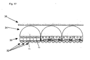
- the medium 10 comprises a phosphorescent layer 30 of phosphorescent elements arranged in pixels, with each pixel comprising three elements 30a, 30b, 30c able to phosphoresce with respectively red, green and blue colour when excited by light of a predetermined frequency, preferably in the ultraviolet (UV) range.
- the exciting light is laser light.
- the frequency of the exciting light may be the same for each of the three colours of phosphor, or each colour of phosphor may be excited by a different frequency.
- a corresponding beam-targeting microlens in a microlens array layer 32 Aligned with each element is a corresponding beam-targeting microlens in a microlens array layer 32, arranged to direct light incident from a range of different angles on the microlens, onto the corresponding element.
- the phosphorescent elements may be formed on the microlens array layer 32 as a coating.
- a colour display lens layer 34 comprising an array of lens each arranged to diffuse light from a corresponding triplet of red, green and blue phosphorescent elements 30a, 30b, 30c.
- the lens layer 34 may be omitted in displays where the different colours from the phosphorescent elements are naturally blended by the eye of the viewer.
- a transparent protective layer 36 may be provided over the lens layer 34, arranged to protect the lens layer 36 and/or to filter out unwanted frequencies emitted by the phosphorescent layer 30.
- Figure 16 is a plan view of the phosphorescent layer 30, showing the array of phosphorescent elements 30a, 30b, 30c surrounded by a black mask 38 to improve contrast.
- the mask 38 is not essential, since the division between pixels is dictated by the microlens array 32.
- the phosphorescent elements have no electrical connection and are completely passive, being excited by light of a specific frequency.
- the phosphorescent decay time is dependant on the type of display required.
- An advantage of this construction is that it requires no back lighting and extremely low levels of energy to provide a high amount of colour and contrast.
- each lens of the lens layer 34 is aligned with a plurality of triplets T1, T2 of phosphorescent elements 30a, 30b, 30c, such that each triplet is visible through the lens layer 34 at a respective different angle.
- corresponding ones of the triplets T1, T2 may be used to generate different images, each image being viewable at a different angle.
- a stereoscopic display may be provided, with a first set of triplets T1 providing a left eye view and a second set of triplets T2 providing a right eye view.
- An optical beam scanner similar to that shown in Figure 14 may be used to scan a modulated beam comprising first, second and third frequencies over the medium 10 of the rewritable display in this embodiment.
- the first, second and third frequencies are selected to excite respective ones of the phosphorescent elements within each triplet.
- the modulated beam may be of a single frequency arranged to excite each of the different phosphorescent elements.
- an array of optical shutters may be used to select which of the phosphorescent elements 30a, 30b, 30c are excited for a specific image, such as the LCD panel 8 shown in Figure 7 .
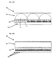
- Figures 18a, 18b and 19 A further embodiment of the light activated display are shown in Figures 18a, 18b and 19 .
- Figure 18a is a cross-section perpendicular to the longitudinal axes of the cylindrical lenses of the lens layer 34
- Figure 18b is a cross-section along a longitudinal axis of a cylindrical lens in the lens layer 34.
- the display construction is similar to that of the embodiment of Figure 17 , except that the microlenses of the microlens array 32 are cylindrical lenses with longitudinal axes perpendicular to the longitudinal axes of the cylindrical lenses in the lens layer 34. These microlenses act as light guides to confine incident light to a specific area of the phosphorescent elements 30.
- the light frequencies required to activate the phosphorescent elements 30 are generated by heterodyning at a point of intersection of two beams.
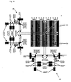
- Figure 19 shows a beam tracking apparatus arranged to steer beams so as to intersect at a required point of the display.
- a first beam tracker 40 is arranged to direct a first beam at a first selectable frequency f1 along a selected cylindrical lens of the microlens array 32.
- a second beam tracker 42 is arranged to direct a second beam at a second selectable frequency f2 perpendicular to the first beam, so as to interest with the first beam at a selected point.
- sum and difference frequencies f1 + f2) and (fl - f2) are generated by heterodyning, and these frequencies illuminate the phosphorescent elements 30 at that point P.
- the phosphorescent elements 30 are arranged to be activated by the sum or difference frequencies caused by heterodyning, so as to emit visible light.
- Different heterodyned frequencies may be selected by selecting the first and second frequencies f1 and f2.
- the phosphorescent elements may be arranged to emit light only when activated by a specific heterodyned frequency.
- a phosphorescent element 30 may be selected to emit light of a specific colour, so that a colour display is provided.
- a phosphorescent element 30 of a specific colour may be selected by precise indexing of the first and second beams, to select only one phosphorescent element 30 at point P.
- the phosphorescent elements 30 may be replaced by a homogenous phosphorescent layer, since the individual pixels are defined by the microlens array 32.
- the display shown in Figure 19 is arranged to produce a lenticular display, by displaying two different views at different angles through the lens layer 34.
- the heterodyning technique is equally applicable to a display arranged to produce a single view, which may be a non-lenticular display.
- the beam trackers 40, 42 may be located substantially in the plane of the display, thereby producing a substantially flat, thin display device.
- the beam trackers may be positioned at adjacent sides of the display, or there may be beam trackers on all sides of the display, so that a separate beam tracker is arranged to illuminate each of the top, bottom, left and right hand sides of the display.
- the phosphorescent elements may be substantially transparent to the unheterodyned frequencies f1, f2, thereby allowing the beams to pass through.
- a plurality of two-dimensional displays may be placed one on top of the other to form a three-dimensional display, with two or more beam scanners 40, 42 arranged to cause their respective beams to intersect at any selected point in the three-dimensional display. This may be used to display a three-dimensional object viewable from almost any angle.
- the three-dimensional display may be cylindrical, formed for example from stacked circular two-dimensional displays.
Landscapes
- Physics & Mathematics (AREA)
- General Physics & Mathematics (AREA)
- Optics & Photonics (AREA)
- Stereoscopic And Panoramic Photography (AREA)
- Heat Sensitive Colour Forming Recording (AREA)
Applications Claiming Priority (3)
| Application Number | Priority Date | Filing Date | Title |
|---|---|---|---|
| GBGB0906689.5A GB0906689D0 (en) | 2009-04-17 | 2009-04-17 | Light reactive media |
| GB0908946.7A GB2469535B (en) | 2009-04-17 | 2009-05-22 | Light reactive media |
| PCT/GB2010/000780 WO2010119269A2 (en) | 2009-04-17 | 2010-04-19 | Light reactive media |
Publications (2)
| Publication Number | Publication Date |
|---|---|
| EP2419792A2 EP2419792A2 (en) | 2012-02-22 |
| EP2419792B1 true EP2419792B1 (en) | 2014-03-19 |
Family
ID=40774600
Family Applications (1)
| Application Number | Title | Priority Date | Filing Date |
|---|---|---|---|
| EP10724886.6A Not-in-force EP2419792B1 (en) | 2009-04-17 | 2010-04-19 | Light reactive media and methods of recording visible images |
Country Status (5)
| Country | Link |
|---|---|
| US (1) | US20120129096A1 (enExample) |
| EP (1) | EP2419792B1 (enExample) |
| JP (1) | JP5631383B2 (enExample) |
| GB (2) | GB0906689D0 (enExample) |
| WO (1) | WO2010119269A2 (enExample) |
Cited By (1)
| Publication number | Priority date | Publication date | Assignee | Title |
|---|---|---|---|---|
| US9358806B2 (en) | 2007-05-29 | 2016-06-07 | Fortium Technologies Ltd. | Laser reactive media and apparatus and method for writing an image onto such media |
Families Citing this family (4)
| Publication number | Priority date | Publication date | Assignee | Title |
|---|---|---|---|---|
| WO2013064971A2 (en) * | 2011-11-02 | 2013-05-10 | Koninklijke Philips Electronics N.V. | A multi-view lighting device, an assembly and a luminaire |
| US9348069B2 (en) | 2014-03-19 | 2016-05-24 | Nike, Inc. | Article having a plurality of optical structures |
| US9575229B2 (en) | 2014-03-19 | 2017-02-21 | Nike, Inc. | Article having a plurality of optical structures |
| WO2016073314A1 (en) * | 2014-11-05 | 2016-05-12 | Nyqamin Dynamics Llc | Overlay display |
Family Cites Families (20)
| Publication number | Priority date | Publication date | Assignee | Title |
|---|---|---|---|---|
| US4333715A (en) * | 1978-09-11 | 1982-06-08 | Brooks Philip A | Moving picture apparatus |
| DE3482544D1 (de) * | 1984-01-13 | 1990-07-19 | Nippon Denki Home Electronics | Bildprojektionsgeraet. |
| EP0219012B1 (de) * | 1985-10-15 | 1993-01-20 | GAO Gesellschaft für Automation und Organisation mbH | Datenträger mit einem optischen Echtheitsmerkmal sowie Verfahren zur Herstellung und Prüfung des Datenträgers |
| JP2746790B2 (ja) * | 1992-03-02 | 1998-05-06 | 富士写真フイルム株式会社 | 立体画像記録方法および立体画像記録装置 |
| JP2704080B2 (ja) * | 1992-02-21 | 1998-01-26 | 富士写真フイルム株式会社 | 立体画像記録方法および立体画像記録装置 |
| JPH0678340A (ja) * | 1992-05-06 | 1994-03-18 | Sanyuu Denshi Kk | 立体表示装置 |
| GB2271464A (en) * | 1992-08-21 | 1994-04-13 | Sharp Kk | Photoemission apparatus. |
| US6226093B1 (en) * | 1993-01-06 | 2001-05-01 | Allen K. Wah Lo | 3D photographic printer using a video monitor for exposure |
| US5801812A (en) * | 1993-01-06 | 1998-09-01 | Image Technology International, Inc. | 3D photographic printer using a digital micro-mirror device for exposure |
| JPH0761146A (ja) * | 1993-08-27 | 1995-03-07 | Toshiba Corp | 記録媒体および画像記録方法 |
| EP1059551A2 (en) * | 1999-06-10 | 2000-12-13 | Eastman Kodak Company | Apparatus for correcting scan line skew in an optical scanner |
| JP4608059B2 (ja) * | 2000-08-03 | 2011-01-05 | 株式会社エス・ディー・エス バイオテック | 殺虫活性を有する蛋白質、その蛋白質をコードするdna、有害生物防除剤及び防除方法。 |
| JP4014389B2 (ja) * | 2001-10-26 | 2007-11-28 | 株式会社リコー | 可逆画像表示媒体、方法および装置 |
| JP4025554B2 (ja) * | 2002-02-14 | 2007-12-19 | 株式会社リコー | 可逆画像記録媒体および方法 |
| JP3873784B2 (ja) * | 2002-03-13 | 2007-01-24 | ヤマハ株式会社 | 光ディスク装置 |
| US8000005B2 (en) * | 2006-03-31 | 2011-08-16 | Prysm, Inc. | Multilayered fluorescent screens for scanning beam display systems |
| US7166420B2 (en) * | 2005-05-27 | 2007-01-23 | Xerox Corporation | Protection of transient documents using a photochromic protective layer |
| US7202006B2 (en) * | 2005-06-20 | 2007-04-10 | Xerox Corporation | Protective layer for reimageable medium |
| US7867672B2 (en) * | 2007-06-13 | 2011-01-11 | Xerox Corporation | Reimageable paper protected against UV light |
| US20080318153A1 (en) * | 2007-06-19 | 2008-12-25 | Qimonda Ag | Photosensitive layer stack |
-
2009
- 2009-04-17 GB GBGB0906689.5A patent/GB0906689D0/en not_active Ceased
- 2009-05-22 GB GB0908946.7A patent/GB2469535B/en not_active Expired - Fee Related
-
2010
- 2010-04-19 WO PCT/GB2010/000780 patent/WO2010119269A2/en not_active Ceased
- 2010-04-19 EP EP10724886.6A patent/EP2419792B1/en not_active Not-in-force
- 2010-04-19 JP JP2012505230A patent/JP5631383B2/ja not_active Expired - Fee Related
- 2010-04-19 US US13/265,302 patent/US20120129096A1/en not_active Abandoned
Cited By (1)
| Publication number | Priority date | Publication date | Assignee | Title |
|---|---|---|---|---|
| US9358806B2 (en) | 2007-05-29 | 2016-06-07 | Fortium Technologies Ltd. | Laser reactive media and apparatus and method for writing an image onto such media |
Also Published As
| Publication number | Publication date |
|---|---|
| GB0908946D0 (en) | 2009-07-01 |
| WO2010119269A2 (en) | 2010-10-21 |
| GB2469535A (en) | 2010-10-20 |
| JP5631383B2 (ja) | 2014-11-26 |
| GB2469535B (en) | 2013-10-09 |
| US20120129096A1 (en) | 2012-05-24 |
| EP2419792A2 (en) | 2012-02-22 |
| JP2012524292A (ja) | 2012-10-11 |
| GB0906689D0 (en) | 2009-06-03 |
| WO2010119269A3 (en) | 2011-01-06 |
Similar Documents
| Publication | Publication Date | Title |
|---|---|---|
| RU2442197C2 (ru) | Многослойные экраны со светоизлучающими полосками для систем отображения со сканирующим лучом | |
| CN106414102B (zh) | 产生类似闪烁的光学效果的光学设备 | |
| CA2624944C (en) | Methods of forming sheeting with a composite image that floats and sheeting with a composite image that floats | |
| US5106288A (en) | Laser based plastic model making workstation | |
| EP2419792B1 (en) | Light reactive media and methods of recording visible images | |
| KR20120005380A (ko) | 다시점 화상 기록 매체 및 진위 판정 방법 | |
| US11300714B2 (en) | 3D/flip/motion photo-substrate, imaging processes, and applications thereof | |
| CN212808686U (zh) | 一种光栅阵列和3d显示装置 | |
| US6069680A (en) | Flying spot laser printer apparatus and a method of printing suitable for printing lenticular images | |
| EP1943102A1 (en) | Ink-less printing | |
| JP5374021B2 (ja) | 屈折率分布型レンズ、屈折率分布型レンズの製造方法、立体画像撮像装置、および立体画像再生装置 | |
| EP0478187A2 (en) | Imaging system | |
| US11667145B2 (en) | Personalizable color-shifting data carrier | |
| KR20190048723A (ko) | 영상 출력용 스크린 및 이를 포함하는 홀로그램 장치 | |
| JP2002103815A (ja) | リライタブル記録媒体及びその記録方法 | |
| JP2006215103A (ja) | 立体画像表示パネル及び製造方法、並びに、立体画像表示装置 | |
| AU3425589A (en) | Laser based plastic model making workstation | |
| JP2000075234A (ja) | レンズ形画像の印刷 |
Legal Events
| Date | Code | Title | Description |
|---|---|---|---|
| PUAI | Public reference made under article 153(3) epc to a published international application that has entered the european phase |
Free format text: ORIGINAL CODE: 0009012 |
|
| 17P | Request for examination filed |
Effective date: 20111117 |
|
| AK | Designated contracting states |
Kind code of ref document: A2 Designated state(s): AT BE BG CH CY CZ DE DK EE ES FI FR GB GR HR HU IE IS IT LI LT LU LV MC MK MT NL NO PL PT RO SE SI SK SM TR |
|
| DAX | Request for extension of the european patent (deleted) | ||
| 17Q | First examination report despatched |
Effective date: 20130315 |
|
| RAP1 | Party data changed (applicant data changed or rights of an application transferred) |
Owner name: ILIT TECHNOLOGIES LTD. |
|
| GRAP | Despatch of communication of intention to grant a patent |
Free format text: ORIGINAL CODE: EPIDOSNIGR1 |
|
| INTG | Intention to grant announced |
Effective date: 20130927 |
|
| GRAS | Grant fee paid |
Free format text: ORIGINAL CODE: EPIDOSNIGR3 |
|
| GRAA | (expected) grant |
Free format text: ORIGINAL CODE: 0009210 |
|
| AK | Designated contracting states |
Kind code of ref document: B1 Designated state(s): AT BE BG CH CY CZ DE DK EE ES FI FR GB GR HR HU IE IS IT LI LT LU LV MC MK MT NL NO PL PT RO SE SI SK SM TR |
|
| REG | Reference to a national code |
Ref country code: GB Ref legal event code: FG4D |
|
| REG | Reference to a national code |
Ref country code: CH Ref legal event code: EP |
|
| REG | Reference to a national code |
Ref country code: IE Ref legal event code: FG4D |
|
| REG | Reference to a national code |
Ref country code: AT Ref legal event code: REF Ref document number: 658042 Country of ref document: AT Kind code of ref document: T Effective date: 20140415 |
|
| REG | Reference to a national code |
Ref country code: DE Ref legal event code: R096 Ref document number: 602010014431 Country of ref document: DE Effective date: 20140430 |
|
| PG25 | Lapsed in a contracting state [announced via postgrant information from national office to epo] |
Ref country code: NO Free format text: LAPSE BECAUSE OF FAILURE TO SUBMIT A TRANSLATION OF THE DESCRIPTION OR TO PAY THE FEE WITHIN THE PRESCRIBED TIME-LIMIT Effective date: 20140619 Ref country code: LT Free format text: LAPSE BECAUSE OF FAILURE TO SUBMIT A TRANSLATION OF THE DESCRIPTION OR TO PAY THE FEE WITHIN THE PRESCRIBED TIME-LIMIT Effective date: 20140319 |
|
| REG | Reference to a national code |
Ref country code: NL Ref legal event code: VDEP Effective date: 20140319 |
|
| REG | Reference to a national code |
Ref country code: AT Ref legal event code: MK05 Ref document number: 658042 Country of ref document: AT Kind code of ref document: T Effective date: 20140319 |
|
| REG | Reference to a national code |
Ref country code: LT Ref legal event code: MG4D |
|
| PG25 | Lapsed in a contracting state [announced via postgrant information from national office to epo] |
Ref country code: FI Free format text: LAPSE BECAUSE OF FAILURE TO SUBMIT A TRANSLATION OF THE DESCRIPTION OR TO PAY THE FEE WITHIN THE PRESCRIBED TIME-LIMIT Effective date: 20140319 Ref country code: SE Free format text: LAPSE BECAUSE OF FAILURE TO SUBMIT A TRANSLATION OF THE DESCRIPTION OR TO PAY THE FEE WITHIN THE PRESCRIBED TIME-LIMIT Effective date: 20140319 Ref country code: CY Free format text: LAPSE BECAUSE OF FAILURE TO SUBMIT A TRANSLATION OF THE DESCRIPTION OR TO PAY THE FEE WITHIN THE PRESCRIBED TIME-LIMIT Effective date: 20140319 |
|
| PG25 | Lapsed in a contracting state [announced via postgrant information from national office to epo] |
Ref country code: HR Free format text: LAPSE BECAUSE OF FAILURE TO SUBMIT A TRANSLATION OF THE DESCRIPTION OR TO PAY THE FEE WITHIN THE PRESCRIBED TIME-LIMIT Effective date: 20140319 Ref country code: LV Free format text: LAPSE BECAUSE OF FAILURE TO SUBMIT A TRANSLATION OF THE DESCRIPTION OR TO PAY THE FEE WITHIN THE PRESCRIBED TIME-LIMIT Effective date: 20140319 |
|
| PG25 | Lapsed in a contracting state [announced via postgrant information from national office to epo] |
Ref country code: CZ Free format text: LAPSE BECAUSE OF FAILURE TO SUBMIT A TRANSLATION OF THE DESCRIPTION OR TO PAY THE FEE WITHIN THE PRESCRIBED TIME-LIMIT Effective date: 20140319 Ref country code: BG Free format text: LAPSE BECAUSE OF FAILURE TO SUBMIT A TRANSLATION OF THE DESCRIPTION OR TO PAY THE FEE WITHIN THE PRESCRIBED TIME-LIMIT Effective date: 20140619 Ref country code: EE Free format text: LAPSE BECAUSE OF FAILURE TO SUBMIT A TRANSLATION OF THE DESCRIPTION OR TO PAY THE FEE WITHIN THE PRESCRIBED TIME-LIMIT Effective date: 20140319 Ref country code: NL Free format text: LAPSE BECAUSE OF FAILURE TO SUBMIT A TRANSLATION OF THE DESCRIPTION OR TO PAY THE FEE WITHIN THE PRESCRIBED TIME-LIMIT Effective date: 20140319 Ref country code: BE Free format text: LAPSE BECAUSE OF FAILURE TO SUBMIT A TRANSLATION OF THE DESCRIPTION OR TO PAY THE FEE WITHIN THE PRESCRIBED TIME-LIMIT Effective date: 20140319 Ref country code: RO Free format text: LAPSE BECAUSE OF FAILURE TO SUBMIT A TRANSLATION OF THE DESCRIPTION OR TO PAY THE FEE WITHIN THE PRESCRIBED TIME-LIMIT Effective date: 20140319 Ref country code: IS Free format text: LAPSE BECAUSE OF FAILURE TO SUBMIT A TRANSLATION OF THE DESCRIPTION OR TO PAY THE FEE WITHIN THE PRESCRIBED TIME-LIMIT Effective date: 20140719 |
|
| REG | Reference to a national code |
Ref country code: DE Ref legal event code: R119 Ref document number: 602010014431 Country of ref document: DE |
|
| PG25 | Lapsed in a contracting state [announced via postgrant information from national office to epo] |
Ref country code: SK Free format text: LAPSE BECAUSE OF FAILURE TO SUBMIT A TRANSLATION OF THE DESCRIPTION OR TO PAY THE FEE WITHIN THE PRESCRIBED TIME-LIMIT Effective date: 20140319 Ref country code: PL Free format text: LAPSE BECAUSE OF FAILURE TO SUBMIT A TRANSLATION OF THE DESCRIPTION OR TO PAY THE FEE WITHIN THE PRESCRIBED TIME-LIMIT Effective date: 20140319 Ref country code: MC Free format text: LAPSE BECAUSE OF FAILURE TO SUBMIT A TRANSLATION OF THE DESCRIPTION OR TO PAY THE FEE WITHIN THE PRESCRIBED TIME-LIMIT Effective date: 20140319 Ref country code: AT Free format text: LAPSE BECAUSE OF FAILURE TO SUBMIT A TRANSLATION OF THE DESCRIPTION OR TO PAY THE FEE WITHIN THE PRESCRIBED TIME-LIMIT Effective date: 20140319 Ref country code: ES Free format text: LAPSE BECAUSE OF FAILURE TO SUBMIT A TRANSLATION OF THE DESCRIPTION OR TO PAY THE FEE WITHIN THE PRESCRIBED TIME-LIMIT Effective date: 20140319 |
|
| REG | Reference to a national code |
Ref country code: CH Ref legal event code: PL |
|
| PG25 | Lapsed in a contracting state [announced via postgrant information from national office to epo] |
Ref country code: PT Free format text: LAPSE BECAUSE OF FAILURE TO SUBMIT A TRANSLATION OF THE DESCRIPTION OR TO PAY THE FEE WITHIN THE PRESCRIBED TIME-LIMIT Effective date: 20140721 |
|
| PLBE | No opposition filed within time limit |
Free format text: ORIGINAL CODE: 0009261 |
|
| REG | Reference to a national code |
Ref country code: FR Ref legal event code: ST Effective date: 20141231 |
|
| STAA | Information on the status of an ep patent application or granted ep patent |
Free format text: STATUS: NO OPPOSITION FILED WITHIN TIME LIMIT |
|
| REG | Reference to a national code |
Ref country code: IE Ref legal event code: MM4A |
|
| PG25 | Lapsed in a contracting state [announced via postgrant information from national office to epo] |
Ref country code: LI Free format text: LAPSE BECAUSE OF NON-PAYMENT OF DUE FEES Effective date: 20140430 Ref country code: DE Free format text: LAPSE BECAUSE OF NON-PAYMENT OF DUE FEES Effective date: 20141101 Ref country code: DK Free format text: LAPSE BECAUSE OF FAILURE TO SUBMIT A TRANSLATION OF THE DESCRIPTION OR TO PAY THE FEE WITHIN THE PRESCRIBED TIME-LIMIT Effective date: 20140319 Ref country code: CH Free format text: LAPSE BECAUSE OF NON-PAYMENT OF DUE FEES Effective date: 20140430 |
|
| REG | Reference to a national code |
Ref country code: DE Ref legal event code: R119 Ref document number: 602010014431 Country of ref document: DE Effective date: 20141101 |
|
| 26N | No opposition filed |
Effective date: 20141222 |
|
| PG25 | Lapsed in a contracting state [announced via postgrant information from national office to epo] |
Ref country code: FR Free format text: LAPSE BECAUSE OF NON-PAYMENT OF DUE FEES Effective date: 20140519 |
|
| PG25 | Lapsed in a contracting state [announced via postgrant information from national office to epo] |
Ref country code: IT Free format text: LAPSE BECAUSE OF FAILURE TO SUBMIT A TRANSLATION OF THE DESCRIPTION OR TO PAY THE FEE WITHIN THE PRESCRIBED TIME-LIMIT Effective date: 20140319 |
|
| PG25 | Lapsed in a contracting state [announced via postgrant information from national office to epo] |
Ref country code: IE Free format text: LAPSE BECAUSE OF NON-PAYMENT OF DUE FEES Effective date: 20140419 |
|
| PG25 | Lapsed in a contracting state [announced via postgrant information from national office to epo] |
Ref country code: SI Free format text: LAPSE BECAUSE OF FAILURE TO SUBMIT A TRANSLATION OF THE DESCRIPTION OR TO PAY THE FEE WITHIN THE PRESCRIBED TIME-LIMIT Effective date: 20140319 |
|
| PG25 | Lapsed in a contracting state [announced via postgrant information from national office to epo] |
Ref country code: MT Free format text: LAPSE BECAUSE OF FAILURE TO SUBMIT A TRANSLATION OF THE DESCRIPTION OR TO PAY THE FEE WITHIN THE PRESCRIBED TIME-LIMIT Effective date: 20140319 |
|
| PG25 | Lapsed in a contracting state [announced via postgrant information from national office to epo] |
Ref country code: SM Free format text: LAPSE BECAUSE OF FAILURE TO SUBMIT A TRANSLATION OF THE DESCRIPTION OR TO PAY THE FEE WITHIN THE PRESCRIBED TIME-LIMIT Effective date: 20140319 |
|
| PG25 | Lapsed in a contracting state [announced via postgrant information from national office to epo] |
Ref country code: GR Free format text: LAPSE BECAUSE OF FAILURE TO SUBMIT A TRANSLATION OF THE DESCRIPTION OR TO PAY THE FEE WITHIN THE PRESCRIBED TIME-LIMIT Effective date: 20140620 |
|
| PG25 | Lapsed in a contracting state [announced via postgrant information from national office to epo] |
Ref country code: TR Free format text: LAPSE BECAUSE OF FAILURE TO SUBMIT A TRANSLATION OF THE DESCRIPTION OR TO PAY THE FEE WITHIN THE PRESCRIBED TIME-LIMIT Effective date: 20140319 Ref country code: LU Free format text: LAPSE BECAUSE OF NON-PAYMENT OF DUE FEES Effective date: 20140419 Ref country code: HU Free format text: LAPSE BECAUSE OF FAILURE TO SUBMIT A TRANSLATION OF THE DESCRIPTION OR TO PAY THE FEE WITHIN THE PRESCRIBED TIME-LIMIT; INVALID AB INITIO Effective date: 20100419 |
|
| PG25 | Lapsed in a contracting state [announced via postgrant information from national office to epo] |
Ref country code: MK Free format text: LAPSE BECAUSE OF FAILURE TO SUBMIT A TRANSLATION OF THE DESCRIPTION OR TO PAY THE FEE WITHIN THE PRESCRIBED TIME-LIMIT Effective date: 20140319 |
|
| PGFP | Annual fee paid to national office [announced via postgrant information from national office to epo] |
Ref country code: GB Payment date: 20220927 Year of fee payment: 13 |
|
| GBPC | Gb: european patent ceased through non-payment of renewal fee |
Effective date: 20230419 |
|
| PG25 | Lapsed in a contracting state [announced via postgrant information from national office to epo] |
Ref country code: GB Free format text: LAPSE BECAUSE OF NON-PAYMENT OF DUE FEES Effective date: 20230419 |
|
| PG25 | Lapsed in a contracting state [announced via postgrant information from national office to epo] |
Ref country code: GB Free format text: LAPSE BECAUSE OF NON-PAYMENT OF DUE FEES Effective date: 20230419 |