EP2418516A2 - Vorrichtung und Verfahren zur Erkennung des Vorhandenseins eines Teilchens eines ferromagnetischen Metalls in einer Verpackung eines paramagnetischen Materials - Google Patents
Vorrichtung und Verfahren zur Erkennung des Vorhandenseins eines Teilchens eines ferromagnetischen Metalls in einer Verpackung eines paramagnetischen Materials Download PDFInfo
- Publication number
- EP2418516A2 EP2418516A2 EP11176515A EP11176515A EP2418516A2 EP 2418516 A2 EP2418516 A2 EP 2418516A2 EP 11176515 A EP11176515 A EP 11176515A EP 11176515 A EP11176515 A EP 11176515A EP 2418516 A2 EP2418516 A2 EP 2418516A2
- Authority
- EP
- European Patent Office
- Prior art keywords
- packaged product
- image
- ferromagnetic metal
- phantom body
- particle
- Prior art date
- Legal status (The legal status is an assumption and is not a legal conclusion. Google has not performed a legal analysis and makes no representation as to the accuracy of the status listed.)
- Withdrawn
Links
Images


Classifications
-
- G—PHYSICS
- G01—MEASURING; TESTING
- G01V—GEOPHYSICS; GRAVITATIONAL MEASUREMENTS; DETECTING MASSES OR OBJECTS; TAGS
- G01V3/00—Electric or magnetic prospecting or detecting; Measuring magnetic field characteristics of the earth, e.g. declination, deviation
- G01V3/14—Electric or magnetic prospecting or detecting; Measuring magnetic field characteristics of the earth, e.g. declination, deviation operating with electron or nuclear magnetic resonance
-
- G—PHYSICS
- G01—MEASURING; TESTING
- G01N—INVESTIGATING OR ANALYSING MATERIALS BY DETERMINING THEIR CHEMICAL OR PHYSICAL PROPERTIES
- G01N24/00—Investigating or analyzing materials by the use of nuclear magnetic resonance, electron paramagnetic resonance or other spin effects
- G01N24/08—Investigating or analyzing materials by the use of nuclear magnetic resonance, electron paramagnetic resonance or other spin effects by using nuclear magnetic resonance
- G01N24/084—Detection of potentially hazardous samples, e.g. toxic samples, explosives, drugs, firearms, weapons
-
- G—PHYSICS
- G01—MEASURING; TESTING
- G01N—INVESTIGATING OR ANALYSING MATERIALS BY DETERMINING THEIR CHEMICAL OR PHYSICAL PROPERTIES
- G01N24/00—Investigating or analyzing materials by the use of nuclear magnetic resonance, electron paramagnetic resonance or other spin effects
- G01N24/08—Investigating or analyzing materials by the use of nuclear magnetic resonance, electron paramagnetic resonance or other spin effects by using nuclear magnetic resonance
- G01N24/085—Analysis of materials for the purpose of controlling industrial production systems
Definitions
- the present invention generally relates to the detection of a metal particle in a packaging.
- the present invention relates to an apparatus and a method for detecting the presence of a particle comprising a ferromagnetic metal in a packaging comprising a paramagnetic and/or diamagnetic material.
- the particle to be detected could comprise steel, stainless steel, iron or similar materials.
- the packaging could for example comprise layers of aluminium and contain for example a pharmaceutical product.
- some products are subject to a series of manufacturing processes during which they may be contaminated by particles of metallic material (and, in particular, ferromagnetic metallic material).
- the particles may typically result from the breakage or the deterioration of some metal parts of the machinery which perform the manufacturing processes.
- contaminating metal particles may be present in the raw materials used in order to obtain the semifinished or end product.
- the granulated material is typically passed through sieves which are made of a ferromagnetic metallic material such as steel. If the meshes of a sieve are damaged, they may break and some small pieces or particles of steel may become intermingled with the granulated product to be packaged. In this case, entire batches of the packaged product may be contaminated. This results in a serious hazard for the safety of the consumer.
- GB 2,462,212 discloses an apparatus for detecting the presence of metal particles in a food product.
- the apparatus comprises a first coil which is operated by a driving circuit and a second coil connected to a detection circuit which detects a signal coming from it.
- the driving circuit supplies the first coil with signals at different frequencies so that any metal particle in the product is subject to scanning at different frequencies.
- WO 2004/104989 discloses magnetic resonance measurement methods for determining the mass of samples and determining the presence of metal in samples.
- the methods include applying a magnetic field in a first direction in an interrogation zone for creating a net magnetization within a sample; applying an alternating magnetic field in a second direction in the interrogating zone for temporarily changing the net magnetization of the sample; monitoring energy emitted by the sample as the net magnetization of the sample returns to its original state and generating an output signal having a characteristic which is proportional to the energy emitted; and comparing the output signal with other data.
- the Applicant has addressed the problem of detecting undesirable metal particles in a packaged product, for example in a pharmaceutical or similar product. More particularly, the Applicant has addressed the problem of detecting undesirable metal particles in a product contained in a packaging comprising aluminium or another paramagnetic and/or diamagnetic material.
- WO 2004/104989 has some drawbacks. Indeed, when it is applied to the detection of metals in products, it provides for detecting a single magnetic resonance signal generated by the entire volume of a "stationary sample" contained in the measurement probe. In case of the simultaneous presence of a metal in the measurement probe, the signal coming from the sample becomes degraded. However, the Applicant has noticed that the method of WO 2004/104989 may have a reduced sensitivity in detecting a small particle of a metal in a packaged product as the particle may cause a negligible degradation of the signal which may not be detectable. Therefore, the method of WO 2004/104989 could not allow making a reliable detection of the metal particles. Moreover, WO 2004/104989 fails to consider detecting particles of metal in a sachet comprising aluminium or another paramagnetic and/or diamagnetic material.
- the object of the present invention is therefore to provide an apparatus and a method for detecting the presence of a particle comprising a ferromagnetic metal in a packaging comprising a paramagnetic and/or diamagnetic material which allows performing such detection in a reliable way.
- the present invention provides a method for checking a packaged product in order to know if said packaged product is free of particles of a ferromagnetic metal or contains a particle of a ferromagnetic metal, wherein said packaged product comprises a packaging comprising a paramagnetic and/or diamagnetic metal.
- the method comprises:
- the slice is profitably situated in the vicinity of said packaged product.
- the slice comprises a surface of the phantom body facing the packaged product.
- the packaging is a sachet.
- the method preferably further comprises conveying said packaged product arranged substantially parallel to said surface.
- Said surface preferably is at a distance less than about 5 cm from said packaged product.
- the reference image corresponds to an image of said packaged product free of ferromagnetic metal particles.
- Said step h) may comprise generating an alarm signal.
- the present invention provides an apparatus for checking a packaged product in order to know if said packaged product is free of particles of a ferromagnetic metal or contains a particle of a ferromagnetic metal, wherein said packaged product comprises a packaging comprising a paramagnetic and/or diamagnetic metal, said apparatus comprising:
- the main magnet may be a permanent magnet or any other magnet which is able to provide a homogeneous static magnetic field.
- said signal detection unit comprises a radiofrequency coil suitable for acquiring said magnetic resonance signals.
- said radiofrequency coil is in a fixed position with respect to said main magnet.
- said image processing module is suitable for generating an alarm signal if said image contains an artefact.
- said packaging is a sachet.
- the present invention provides a system for conveying a packaged product, wherein said packaged product comprises a packaging comprising a paramagnetic and/or diamagnetic metal, said system comprising a conveying device and an apparatus for checking said packaged product in order to know if said packaged product is free of particles of a ferromagnetic metal or contains a particle of a ferromagnetic metal, said apparatus being an apparatus as set forth above.
- the conveying device may be partially housed inside a longitudinal cavity of said main magnet.
- the packaging may be a sachet, wherein said conveying device conveys the packaged product arranged substantially parallel to said phantom body.
- a product is understood as meaning a given quantity of a solid substance, including also a substance in the form of a powder or granules which does not give rise to a magnetic resonance signal.
- a product could consist of a pharmaceutical, parapharmaceutical, homeopathic, food or cosmetic product.
- a product may be in the form of effervescent granules or soluble granules.
- paramagnetic when used in conjunction with a magnetized material, indicates that the material has a relative magnetic permeability ⁇ r which is constant, with respect to the magnetic field inducing magnetization, and greater than 1 (typically greater than 1 by a few ppm).
- ⁇ r 1.000022
- diamagnetic when used in conjunction with a magnetized material, indicates that the material has a relative magnetic permeability ⁇ r which is constant, with respect to the magnetic field inducing magnetization, and less than 1 (typically less than 1 by a few ppm). All materials have a diamagnetic component in their magnetic properties, even though in the case of paramagnetic and ferromagnetic materials it is masked by the other preponderant magnetic effects.
- ferromagnetic when used in conjunction with a magnetized metal, indicates that the metal has a relative magnetic permeability ⁇ r which is not constant, depending on the magnetic field inducing the magnetization, and much greater than 1.
- ferromagnetic materials are steel, iron and nickel.
- a packaging could be a substantially flat packaging such as a single-dose sachet formed by a layered material in which one of said layers consists of an aluminium foil.
- the expression "packaged product” is understood as meaning the assembly consisting of the product and its packaging.
- a particle comprising a ferromagnetic metal is understood as meaning a metal body, for example an iron, steel, brass or chrome body.
- a particle has a size of a few millimetres and any shape.
- a particle has a volume not less than the volume of a sphere with a 0.5 mm diameter.
- the adjective "contaminated”, when used in conjunction with a packaged product, indicates that the packaged product contains one or more particles and is therefore contaminated by their presence.
- an artefact in an image is understood as meaning an area of the image whose colour is in contrast with the colour of the neighbour areas of the image.
- an artefact could be a black area over a grey or white (possibly homogeneous) background.
- the detection apparatus comprises a main magnet, a signal detection unit and a control and - where applicable - signalling unit (in short, control unit).
- the main magnet is configured to generate a static magnetic field.
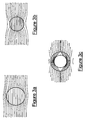
- a packaged product is passed within the static magnetic field. If the packaged product does not contain a particle, the static magnetic field is not disturbed by the passing of the packaged product, as shown in Figures 3a and 3b . However, if the packaged product is contaminated and contains at least one particle, the static magnetic field is disturbed (i.e. its homogeneity is locally distorted) by the passing of the contaminated packaged product, as shown in Figure 3c .
- the signal detection unit detects magnetic resonance signals generated by elementary volumetric portions (which may be termed voxels) of a slice of a phantom body, which is especially configured (indeed, the packaged product does not give rise to a magnetic resonance signal), located within the detection apparatus and in the proximity of the packaged product. Then, the control unit processes the detected signals in order to generate an image of the phantom body slice: usually the signal detected in each voxel is displayed as the brightness of a point in the image (pixel). If the packaged product is contaminated, some magnetic resonance signals, namely the signals coming from the voxels in the vicinity of the particle, are disturbed, due to the local lack of homogeneity of the static magnetic field, and the generated slice image is indicative of this disturbance. Finally, the control unit processes and/or stores the images and if necessary generates a corresponding signalling event. Thanks to the present invention, if a contaminated packaged product is detected, it is discarded without adversely affecting the other packaged products which are not contaminated.
- Figure 1 schematically shows a detection apparatus 1 according to an embodiment of the present invention.
- the detection apparatus 1 preferably comprises a main magnet 11, a signal detection unit 12 and a control unit 13.
- the main magnet 11 is preferably in the form of a hollow cylinder and defines a cylindrical cavity 126 along its longitudinal axis (axis z in Figure 1 ).
- the main magnet 11 may be in the form of a C or U, i.e. with a longitudinal slit.
- the signal detection unit 12 comprises three gradient coils 122, a radiofrequency coil 123 and a phantom body 124. Preferably it also comprises a radiofrequency screen 125.
- the gradient coils 122 and radiofrequency coil 132 preferably comprise one or more windings of a wire of electrically conductive material, for example copper. As shown in Figure 1 , the coils are preferably housed inside the longitudinal cavity 126 of the main magnet 11 and are arranged coaxially therewith with respect to the longitudinal axis of the main magnet 11. The windings may assume different configurations which will not be further described since they are not relevant to the present invention. Preferably, the position of the gradient coils 122 and the radiofrequency coil 123 is fixed with respect to the main magnet 11.
- the phantom body 124 is preferably housed inside the longitudinal cavity 126 of the main magnet 11.
- the phantom body 124 is preferably fixed with respect to the main magnet 11.
- the main magnet 11 is preferably suitable for generating a static magnetic field B 0 which is substantially homogeneous in at least one portion of its longitudinal cavity 126.
- the main magnet 11 may be, for example, a permanent magnet or any other magnet which is able to provide a homogeneous static magnetic field.
- the strength of the static magnetic field B 0 may be a few tenths of a Tesla, for example between about 0.3 T and about 0.4 T. However, higher or lower field strength values could be used.
- the strength of the static magnetic field B 0 is substantially homogeneous in the region of the phantom body 124.
- a variation of the static magnetic field B 0 is defined as the ratio [(B 0max -B 0min )/B 0av ]x10 6 , B 0max .
- B 0min and Boav being respectively the maximum, minimum and mean magnetic field strengths inside a sphere having a diameter such as to contain the phantom body 124, the variation is preferably less than about 5 ppm.
- the diameter of the abovementioned sphere is typically related to the physical dimensions of the phantom body 124.
- the diameter of the sphere inside which the strength of the static magnetic field B 0 is substantially homogeneous may be 25 cm.
- this sphere is contained within the longitudinal cavity of the magnet 11 and is substantially in a position corresponding to the geometric centre of the longitudinal cavity of the magnet 11.
- the gradient coils 122 are preferably suitable for generating respective static magnetic fields, the strength of which is linearly variable along the directions of the axes x, y and z.
- the radiofrequency coil 123 is preferably suitable for generating an alternating magnetic field B 1 , in the transverse direction with respect to the static magnetic field B 0 , and capture a magnetic resonance signal from the phantom body 124, as it will be described in greater detail hereinafter.
- the phantom body 124 is preferably a body having the shape of a parallelepiped or of a cylinder with a circular cross-section made of a plastic material, such as for example plexiglass, virgin polystyrene - TC, or glass, and is hollow or partly hollow.
- the phantom body 124 is filled with a composition suitable for generating a magnetic resonance signal, as will be described in greater detail in the present description hereinafter.
- the composition contained inside the phantom body 124 may be a solution of water and copper sulphate.
- This solution may for example contain 770 mg of copper sulphate pentahydrate CuSO 4 ⁇ 5H 2 O, 1 ml of a 1 molar solution of sodium azide NaN 3 , 0.15 ml of a 1 normal solution of sulphuric acid H 2 SO 4 and double distilled water.
- the composition contained in the phantom body 124 may be a paramagnetic aqueous solution (for example with nickel or manganese) or a pure gel of gelatine, agar, polyvinyl alcohol, silicone, polyacrylamide, agarose, organic doped gel, a paramagnetic doped gel or a reverse micelle solution.
- the radiofrequency screen 125 preferably surrounds the main magnet 11, the gradient coils 122 and the radiofrequency coil 123.
- This screen 125 is preferably a Faraday cage suitable for screening the signal detecting unit 12 in order to prevent the radiofrequency signals supplied from the exterior, for example from the control unit 13, from interfering with the signal detecting unit 12, for example being captured by the radiofrequency coil 123.
- the control unit 13 of the detection apparatus 1 comprises a control module 131, a gradient waveform generator 132, a gradient amplifier 133, a radiofrequency waveform generator 134, a radiofrequency amplifier 135, a radiofrequency receiver 136, a data processing module 137 and an image processing module 138.
- the control unit 13 may comprise further components not shown in Figure 1 since they are not relevant for the purposes of the present description.
- control module 131 is connected to the gradient waveform generator 132 which is in turn connected to the gradient amplifier 133.
- the gradient amplifier 133 is preferably connected to the gradient coils 122 of the signal detection unit 12.
- control module 131 is connected to the radiofrequency waveform generator 134.
- the radiofrequency waveform generator 134 is preferably connected to the radiofrequency amplifier 135 which is in turn connected to the radiofrequency coil 123 of the signal detection unit 12.
- the radiofrequency coil 123 is moreover preferably connected to the radiofrequency receiver 136 which is in turn connected in cascade to the data processing module 137 and to the control module 131.
- the control module 131 is preferably connected to the image processing module 138.
- control module 131 is configured to control the operation of the detection apparatus 1 and comprises a user interface with a data input peripheral (e.g. a keyboard), a display device (e.g. a monitor) and an audio reproduction device (e.g. loudspeakers), not shown in Figure 1 .
- control module 131 preferably comprises a processor (also not shown in Figure 1 ) and one or more storage devices (e.g. hard disks).
- the detection apparatus 1 is configured to co-operate with a machine for conveying packaged products. This machine is not shown in the figures because it is not relevant for the purposes of the present invention.
- This machine typically comprises a device for conveying packaged products, such as a conveyor belt 14, which is schematically shown in Figure 1 .
- the conveyor belt 14 is suitable for conveying a plurality of packaged products 15 arranged in a row or in several adjacent rows.
- the plurality of packaged products 15 may be sachets, containing granules or the like, arranged substantially horizontally on the conveyor belt.
- the conveying direction is shown by an arrow indicated by the letter A.
- the conveyor belt 14 passes through the longitudinal cavity 126 of the main magnet 11. Therefore, the packaged products 15 in turn pass through the longitudinal cavity 126 in a direction parallel to the longitudinal axis of the main magnet 11 and pass through the static magnetic field B 0 generated by the main magnet 11.
- the position of the conveyor belt 14 is such that, when each packaged product conveyed on the conveyor belt 14 is in the vicinity of the phantom body 124 (i.e. immediately underneath it), the distance between the top surface of the packaged product and the bottom surface of the phantom body 124 is such as to allow detection also of small disturbances of the static magnetic field B 0 caused by the passing of a small particle present inside a contaminated packaged product.
- the distance could be less than about 5 cm. In some embodiments, such a distance is less than about 3 cm. In other embodiments the distance is less than about 2 cm or even less than about 1 cm.
- the distance between the top surface of the sachet and the bottom surface of the phantom body 124 must not be greater than about 1 cm.
- the conveyor belt 14 is made of paramagnetic and/or diamagnetic material, in particular a plastic material, for example Teflon.
- the conveyor belt 14 is operated by a motor situated outside the radiofrequency screen 125.
- an initialisation step of the detection apparatus 1 is performed. This step is not indicated in Figure 2 .
- the operator via the data input peripheral of the control module 131, sets up the control module 131 so that, during a subsequent operation, it sends a command to the gradient waveform generator 132 and to the radiofrequency waveform generator 134.
- the commands sent to the generators 132 and 134 produce the generation of respective excitation sequences so as to feed, respectively, the gradient coils 122 and the radiofrequency coil 123 and so as to detect, afterwards, a magnetic resonance signal which allows the generation of an image of the phantom body 124.
- a packaged product is positioned on the conveyor belt 14 and that the conveyor belt 14 conveys it through the longitudinal cavity 126 of the main magnet 11. It is also assumed that the product inside the packaging may comprise one or more particles of a ferromagnetic metal.
- the behaviour of a packaged product plunged into the static magnetic field B 0 varies depending on whether the packaged product comprises only diamagnetic and/or paramagnetic materials or also ferromagnetic metals.
- a diamagnetic or paramagnetic material when plunged into the static magnetic field B 0 , does not substantially alter the homogeneity of the field, while a ferromagnetic metal instead considerably alters the homogeneity thereof.
- the packaged product does not contain any particle of ferromagnetic metallic material, when plunged into the static magnetic field B 0 , it does not substantially alter its homogeneity.
- the packaged product contains at least one particle, when plunged into the static magnetic field B 0 , it significantly alters locally its homogeneity.
- the strength of the static magnetic field B 0 is not homogeneous inside the particle and in the vicinity thereof.
- control module 131 sends a command both to the gradient waveform generator 132 and to the radiofrequency waveform generator 134 so that each of them generates the respective excitation sequence.
- the gradient waveform generator 132 generates an excitation sequence in the form of a sequence of gradient pulses which is suitably amplified by the gradient amplifier 133 and modulates three different pulse current signals which feed the three gradient coils 122.
- the radiofrequency waveform generator 134 generates a radiofrequency monochromatic signal which is suitably modulated in order to provide the respective excitation sequence in the form of a sequence of radiofrequency pulses.
- This sequence of radiofrequency pulses is suitably amplified by the radiofrequency amplifier 135 and modulates a pulse current signal which feeds the radiofrequency coil 123.
- the excitation sequences are sequences of the "gradient echo” type, for example known Field Echo - Echo Planar Imaging (FE EPI) sequences.
- FE EPI Field Echo - Echo Planar Imaging
- Such a sequence is in fact a fast sequence, which allows acquisition of an image in a time compatible with the speed of the conveyor belt 14 and is particularly sensitive to lack of homogeneity of the static magnetic field B 0 .
- each of the gradient coils 122 In the presence of the pulses of the sequence of gradient pulses, the current flowing inside each of the gradient coils 122 generates a magnetic field which is superimposed on the static magnetic field B 0 , producing an overall static magnetic field having a strength varying in a linear manner inside the longitudinal cavity 126 along the axes x, y and z.
- the current flowing inside the radiofrequency coil 122 In the presence of the pulses of the sequence of radiofrequency pulses, the current flowing inside the radiofrequency coil 122 generates an alternating radiofrequency magnetic field B 1 in a transverse direction with respect to the static magnetic field B 0 .
- the combined effect of the alternating radiofrequency magnetic field B 1 and the linear variation in strength of the overall static magnetic field is such that, during a step 202, it induces in the radiofrequency coil 123 an alternating current.
- This current is indicative of a number of magnetic resonance signals relating to the voxels into which a slice of the phantom body 124 (and, in particular, to the composition contained therein), in a plane parallel to the conveyor belt 14, may be decomposed.
- the slice of the phantom body 124 whose voxels generate the detected magnetic resonance signals is a coronal section substantially in the vicinity of the bottom surface of the phantom body 124.
- the alternating current induced in the radiofrequency coil 123 is received by the radiofrequency receiver 136 and forwarded to the data processing unit 137.
- the data processing unit 137 preferably performs an analog-to-digital conversion of the alternating current acquired during step 202 and processes the digital data thus obtained so as to obtain an image of the slice of the phantom body 124 which generated the magnetic resonance signals.
- the image may be forwarded to the control module 131, displayed by means of the display peripheral connected to the control module 131 and stored inside a storage device of the control module 131.
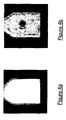
- Figures 4a and 4b show, by way of example, two images of a slice of a phantom body in the vicinity of a packaged product without particles and a packaged product contaminated by a particle of ferromagnetic metal, respectively.
- the product is a granulated pharmaceutical product contained inside a laminated aluminium sachet.
- the images shown in Figures 4a and 4b were obtained using a magnetic resonance apparatus , with a static permanent magnetic field of 0.4 T and a phantom body, in the form of a parallelepiped, containing a solution of water and copper sulphate with dimensions 15 cm x 10 cm x 3 cm.
- the excitation sequences used to feed the gradient coils and the radiofrequency coil of the apparatus are FE EPI sequences with a duration of 1 second.
- the image in Figure 4a relates to a slice of the phantom body in the vicinity of the packaged product not comprising any particle of ferromagnetic metal.
- the image in Figure 4b is an image of the same slice of the phantom body when a packaged product is contaminated and comprises a particle of ferromagnetic metal, in particular a particle of steel with a diameter of about 0.5 mm.
- the image in Figure 4a has a zone, corresponding to the slice of the phantom body, with a homogeneous colour in that the static magnetic field present in the longitudinal cavity of the detection apparatus is homogeneous and hence the magnetic resonance signals generated by the voxels of the phantom body slice are not disturbed by the presence of the packaged product.
- the image in Figure 4b instead contains an artefact, namely a darker coloured region. In Figure 4b such an artefact is located about in the centre of the phantom body section. This artefact is due to a lack of homogeneity of the static magnetic field produced by the presence of the particle inside the packaged product.
- the lack of homogeneity is local in that it is confined to a region in the proximity of the particle position when the contaminated packaged product passes beneath the phantom body. Due to this local lack of homogeneity, only the magnetic resonance signals generated by voxels corresponding to elementary volumetric portions of the phantom body located in the proximity of the particle are disturbed and provide for the darker region in the image of Figure 4b , while the magnetic resonance signals of the other voxels are substantially undisturbed.
- the images acquired by the detection apparatus 1 therefore indicate a possible disturbance of the static magnetic field. Therefore, advantageously, the presence of the particle may be effectively detected by means of inspection of the images of the phantom body 124 acquired by the detection apparatus 1 while the packaged products to be analysed are passed underneath it. If a particle of ferromagnetic metal is present inside a package, wherever it is, the image of a slice, which covers the total package surface, will certainly show some altered pixels resulting in an artefact of the acquired image. In other embodiments, the phantom body is arranged below the packaged product. In this case, the slice "covers from below" the total package surface.
- the acquired image is forwarded to the image processing module 138 which compares the acquired image with a reference image relating to the same section of the phantom body 124.
- This reference image could be, for example, an image acquired in the absence of a packaged product or in the presence of a packaged product which is not contaminated.
- the image processing module 138 during a step 205 determines whether an artefact is present in the acquired image.
- the image processing module 138 may, for example, implement an image recognition algorithm based on statistics relating to the presence of various shades of grey or colours in the images, or based on the recognition of sudden changes in the luminosity of the images, or the like.
- the recognition algorithm implemented by the image processing module 138 could be based on techniques which use statistical methods such as the PCA (Principal Component Analysis) technique, ICA (Independent Component Analysis) technique, LDA (Linear Discriminant Analysis) technique, or the like.
- the image processing module 138 If the image acquired by the detection apparatus 1 contains an artefact, the image processing module 138 generates an alarm signal.
- the alarm signal is then sent to the control module 131 which preferably, during a step 206, sends a command to its display device so that it displays an alarm message and/or a command to its audio reproduction device so that it emits an alarm sound.
- the control module 131 preferably, during a step 206, sends a command to its display device so that it displays an alarm message and/or a command to its audio reproduction device so that it emits an alarm sound.
- an operator monitoring the operation of the detection apparatus 1 may be alerted as to the presence of a packaged product containing one or more contaminating particles of ferromagnetic metal and therefore decide to interrupt the movement of the conveyor belt 14 and remove the contaminated packaged product from the line.
- the image acquisition operation is preferably repeated periodically by the detection apparatus 1.
- the repetition period of the image acquisition operation is preferably chosen depending on the duration of the excitation sequences and a packaging interval of the machine for conveying packaged products cooperating with the detection apparatus 1.
- the packaging interval is essentially the interval occurring between the two instants when two successive packaged products 15 are placed on the conveyor belt 14, the speed of the conveyor belt depending on this interval.
- the excitation sequences may have a duration of 1 second, while the packaging interval may be of about 2 seconds.
- the repetition period of the image acquisition operation is chosen so that, during each repetition period, an image of the phantom body 124 relating to the passage of a packaged product 15 (or several adjacent packaged products) conveyed on the conveyor belt 14 when the latter is situated next to the phantom body 124 (i.e. immediately underneath it) is acquired.
- images of the phantom body 124 relating to all the products in a row (or in adjacent rows) on the conveyor belt 14 are then acquired. In this way, a precise check may be performed so that only the products which are actually contaminated may be removed, where necessary, from the line.
- the detection apparatus 1 described above allows detecting the presence of a particle of a ferromagnetic metal inside a packaging comprising a paramagnetic and/or diamagnetic material in a simple, rapid and reliable manner.
- the method of the present invention is more reliable than the method of WO 2004/104989 .
- the present invention provides for acquiring an image indicative of a set of magnetic resonance signals related to the different voxels of a slice of the phantom body (e.g. immediately above the packaged product), which are distributed in space.
- a metal particle in a packaged product passes underneath the phantom body, since the lack of homogeneity of the static magnetic field is localized around the particle, the particle disturbs the magnetic resonance signals generated by the voxels located in its proximity in the plane of the slice.
- the method of the present invention is more sensitive than the method of WO 2004/104989 .
- the local disturbance due to the particle is to be detected on a single magnetic resonance signal related to the whole stationary sample.
- the disturbance may be negligible with respect to this "global" signal and hardly detectable.
- the local disturbance due to the particle is to be detected on local magnetic resonance signals and it is hence more evident and immediately recognizable by processing the generated image. Therefore, the method of the present invention provides for a more reliable detection of metal particles in packaged products.
- the intensity of the static magnetic field needed to achieve such a detection is reduced to values of tenths of Tesla, which are not hazardous for the safety of the operators.
- the radiofrequency coil and the phantom body used for acquisition of the images are in a fixed position inside the main magnet. This advantageously avoids the need for centring scans aimed to calibrate the apparatus and then simplifies the operation thereof.
- the radiofrequency waveform generator may generate a monochromatic wave having always the same frequency during each repetition period of the acquisition operation since it is not required to acquire images relating to different slices of the phantom body. Each slice of the phantom body in fact corresponds to a particular frequency.
- the image acquisition operation is therefore advantageously rapid and simple from a computational point of view.
- the control module does not have to store a set of different excitation sequences since the gradient coils and the radiofrequency coil may be operated using always the same excitation frequency.
- the image acquisition unit of the detection apparatus may comprise two phantom bodies.
- the two phantom bodies are substantially the same.
- the image acquisition unit comprises a top phantom body and a bottom phantom body located in fixed and diametrically opposite positions relative to the longitudinal axis of the main magnet.
- the bottom phantom body and the top phantom body are vertically aligned. The relative position of the top phantom body, the conveyor belt and the bottom phantom body is such that a packaged product which, on the conveyor belt, passes next to the position of the top phantom body and bottom phantom body is situated at a minimum distance from both of them.
- both images are acquired, i.e. one for a slice of the top phantom body and one for a slice of the bottom phantom body.
- both images may be compared with the reference image in order to detect the presence of a particle so as to increase the reliability of the detection process.
Landscapes
- Physics & Mathematics (AREA)
- High Energy & Nuclear Physics (AREA)
- Life Sciences & Earth Sciences (AREA)
- General Physics & Mathematics (AREA)
- Health & Medical Sciences (AREA)
- Pathology (AREA)
- Biochemistry (AREA)
- General Health & Medical Sciences (AREA)
- Analytical Chemistry (AREA)
- Immunology (AREA)
- Chemical & Material Sciences (AREA)
- Engineering & Computer Science (AREA)
- Environmental & Geological Engineering (AREA)
- Geology (AREA)
- Remote Sensing (AREA)
- General Life Sciences & Earth Sciences (AREA)
- Geophysics (AREA)
- Bioinformatics & Cheminformatics (AREA)
- Molecular Biology (AREA)
- Toxicology (AREA)
- Magnetic Resonance Imaging Apparatus (AREA)
Priority Applications (1)
| Application Number | Priority Date | Filing Date | Title |
|---|---|---|---|
| EP11176515.2A EP2418516A3 (de) | 2010-08-12 | 2011-08-04 | Vorrichtung und Verfahren zur Erkennung des Vorhandenseins eines Teilchens eines ferromagnetischen Metalls in einer Verpackung eines paramagnetischen Materials |
Applications Claiming Priority (2)
| Application Number | Priority Date | Filing Date | Title |
|---|---|---|---|
| EP10425274 | 2010-08-12 | ||
| EP11176515.2A EP2418516A3 (de) | 2010-08-12 | 2011-08-04 | Vorrichtung und Verfahren zur Erkennung des Vorhandenseins eines Teilchens eines ferromagnetischen Metalls in einer Verpackung eines paramagnetischen Materials |
Publications (2)
| Publication Number | Publication Date |
|---|---|
| EP2418516A2 true EP2418516A2 (de) | 2012-02-15 |
| EP2418516A3 EP2418516A3 (de) | 2014-02-19 |
Family
ID=44014458
Family Applications (1)
| Application Number | Title | Priority Date | Filing Date |
|---|---|---|---|
| EP11176515.2A Withdrawn EP2418516A3 (de) | 2010-08-12 | 2011-08-04 | Vorrichtung und Verfahren zur Erkennung des Vorhandenseins eines Teilchens eines ferromagnetischen Metalls in einer Verpackung eines paramagnetischen Materials |
Country Status (3)
| Country | Link |
|---|---|
| US (1) | US20120268117A1 (de) |
| EP (1) | EP2418516A3 (de) |
| CA (1) | CA2748104A1 (de) |
Cited By (5)
| Publication number | Priority date | Publication date | Assignee | Title |
|---|---|---|---|---|
| EA025704B1 (ru) * | 2012-03-19 | 2017-01-30 | Ооо "Пмт И К" | Устройство и способ проверки груза в контейнере |
| CN107110931A (zh) * | 2014-09-05 | 2017-08-29 | 海珀菲纳研究股份有限公司 | 用于磁共振成像的铁磁增强 |
| US10444310B2 (en) | 2016-11-22 | 2019-10-15 | Hyperfine Research, Inc. | Portable magnetic resonance imaging methods and apparatus |
| US10539637B2 (en) | 2016-11-22 | 2020-01-21 | Hyperfine Research, Inc. | Portable magnetic resonance imaging methods and apparatus |
| US10813564B2 (en) | 2014-11-11 | 2020-10-27 | Hyperfine Research, Inc. | Low field magnetic resonance methods and apparatus |
Families Citing this family (6)
| Publication number | Priority date | Publication date | Assignee | Title |
|---|---|---|---|---|
| US9585202B2 (en) * | 2011-05-20 | 2017-02-28 | Cooktek Induction Systems, Llc | Induction-based food holding/warming system and method |
| PL2867291T3 (pl) * | 2012-06-28 | 2019-02-28 | Dow Global Technologies Llc | Materiał kompozytowy, sposób jego wytwarzania i wytworzone z niego wyroby |
| JP6424144B2 (ja) * | 2015-06-29 | 2018-11-14 | 株式会社荏原製作所 | 金属検知用センサー及び該センサーを用いた金属検知方法 |
| US10356853B2 (en) | 2016-08-29 | 2019-07-16 | Cooktek Induction Systems, Llc | Infrared temperature sensing in induction cooking systems |
| GB2556926A (en) * | 2016-11-25 | 2018-06-13 | Metrasens Ltd | Monitoring system for a detection system |
| KR102393529B1 (ko) * | 2020-08-18 | 2022-05-02 | 제만석 | 비자성 파이프 검사용 자성 금속 이물질 검출 장치 |
Citations (2)
| Publication number | Priority date | Publication date | Assignee | Title |
|---|---|---|---|---|
| WO2004104989A2 (en) | 2003-05-16 | 2004-12-02 | The Boc Group, Inc. | Nmr measuring system |
| GB2462212A (en) | 2005-02-16 | 2010-02-03 | Illinois Tool Works | Multi-frequency metal detector for detecting metal in food products |
Family Cites Families (8)
| Publication number | Priority date | Publication date | Assignee | Title |
|---|---|---|---|---|
| US5270650A (en) * | 1992-06-11 | 1993-12-14 | Abbott Laboratories | Non-destructive detection of spoilage using nuclear magnetic resonance spectroscopy |
| US6333629B1 (en) * | 1999-07-22 | 2001-12-25 | Intermagnetics General Corporation | Method for non-invasively and without contact, inspecting foil enclosed packages, using magnetic resonance techniques |
| MXPA05000724A (es) * | 2002-07-17 | 2005-04-08 | Univ California | Metodos y dispositivos para el analisis de recipientes sellados. |
| US7064548B2 (en) * | 2004-04-30 | 2006-06-20 | The Boc Group, Inc. | RF probe apparatus for NMR check weighing system |
| WO2006122356A1 (en) * | 2005-05-16 | 2006-11-23 | Qrscience Pty Ltd | A system and method for improving the analysis of chemical substances using nqr |
| US7355402B1 (en) * | 2006-11-20 | 2008-04-08 | Echo Medical Systems, Llc | Method and apparatus for hazardous liquid detection |
| US8390286B2 (en) * | 2007-05-18 | 2013-03-05 | Los Alamos National Security, Llc | Ultra-low field nuclear magnetic resonance and magnetic resonance imaging to discriminate and identify materials |
| US8019466B2 (en) * | 2007-06-14 | 2011-09-13 | Northrop Grumman Systems Corporation | Devices and methods for detecting hazardous materials |
-
2011
- 2011-08-04 EP EP11176515.2A patent/EP2418516A3/de not_active Withdrawn
- 2011-08-05 CA CA2748104A patent/CA2748104A1/en not_active Abandoned
-
2012
- 2012-03-23 US US13/429,046 patent/US20120268117A1/en not_active Abandoned
Patent Citations (2)
| Publication number | Priority date | Publication date | Assignee | Title |
|---|---|---|---|---|
| WO2004104989A2 (en) | 2003-05-16 | 2004-12-02 | The Boc Group, Inc. | Nmr measuring system |
| GB2462212A (en) | 2005-02-16 | 2010-02-03 | Illinois Tool Works | Multi-frequency metal detector for detecting metal in food products |
Cited By (10)
| Publication number | Priority date | Publication date | Assignee | Title |
|---|---|---|---|---|
| EA025704B1 (ru) * | 2012-03-19 | 2017-01-30 | Ооо "Пмт И К" | Устройство и способ проверки груза в контейнере |
| CN107110931A (zh) * | 2014-09-05 | 2017-08-29 | 海珀菲纳研究股份有限公司 | 用于磁共振成像的铁磁增强 |
| US10466327B2 (en) | 2014-09-05 | 2019-11-05 | Hyperfine Research, Inc. | Automatic configuration of a low field magnetic resonance imaging system |
| US11397233B2 (en) | 2014-09-05 | 2022-07-26 | Hyperfine Operations, Inc. | Ferromagnetic augmentation for magnetic resonance imaging |
| US10813564B2 (en) | 2014-11-11 | 2020-10-27 | Hyperfine Research, Inc. | Low field magnetic resonance methods and apparatus |
| US10444310B2 (en) | 2016-11-22 | 2019-10-15 | Hyperfine Research, Inc. | Portable magnetic resonance imaging methods and apparatus |
| US10539637B2 (en) | 2016-11-22 | 2020-01-21 | Hyperfine Research, Inc. | Portable magnetic resonance imaging methods and apparatus |
| US10775454B2 (en) | 2016-11-22 | 2020-09-15 | Hyperfire Research, Inc. | Portable magnetic resonance imaging methods and apparatus |
| US11366188B2 (en) | 2016-11-22 | 2022-06-21 | Hyperfine Operations, Inc. | Portable magnetic resonance imaging methods and apparatus |
| US11841408B2 (en) | 2016-11-22 | 2023-12-12 | Hyperfine Operations, Inc. | Electromagnetic shielding for magnetic resonance imaging methods and apparatus |
Also Published As
| Publication number | Publication date |
|---|---|
| CA2748104A1 (en) | 2012-02-12 |
| US20120268117A1 (en) | 2012-10-25 |
| EP2418516A3 (de) | 2014-02-19 |
Similar Documents
| Publication | Publication Date | Title |
|---|---|---|
| EP2418516A2 (de) | Vorrichtung und Verfahren zur Erkennung des Vorhandenseins eines Teilchens eines ferromagnetischen Metalls in einer Verpackung eines paramagnetischen Materials | |
| US8390286B2 (en) | Ultra-low field nuclear magnetic resonance and magnetic resonance imaging to discriminate and identify materials | |
| US20020190724A1 (en) | Pulsed eddy current two-dimensional sensor array inspection probe and system | |
| KR20030062414A (ko) | 금속이물검지방법과 그 장치 | |
| CA2259234A1 (en) | Coin discrimination apparatus and method | |
| JP2008512689A (ja) | 危険物マルチ検出システム | |
| CN1210270A (zh) | 用于检测非磁性制品中的磁性物质的方法和装置 | |
| JP2018063229A (ja) | 金属異物検知装置 | |
| CN104914389B (zh) | 基于自旋锁定技术探测震荡磁场的磁共振成像方法及应用 | |
| JP5458436B2 (ja) | 金属物の形状判定方法 | |
| CN101573608B (zh) | 用于影响和/或检测和/或定位作用区域中的磁性粒子的设备和方法 | |
| KR20180103306A (ko) | 금속이물 검출장치 | |
| JP4621880B2 (ja) | 異物検知方法及び異物検知装置 | |
| US7064548B2 (en) | RF probe apparatus for NMR check weighing system | |
| US20140266172A1 (en) | Apparatus for magnetic particle imaging | |
| US6484595B1 (en) | Device for determining the disintegration time of compressed pharmaceutical mold bodies, such as tablets and capsules, as well as a method for this purpose | |
| JP2013140054A (ja) | 常磁性材料のパッケージ内における強磁性金属粒子の存在を検出する装置及び方法 | |
| JP3875161B2 (ja) | 金属探知機用センサーと金属探知機 | |
| JP6744846B2 (ja) | 金属検出装置および金属検出方法 | |
| Ricci et al. | Magnetic imaging and machine vision NDT for the on-line inspection of stainless steel strips | |
| JP5418945B2 (ja) | 金属探知機用センサーコイル及び金属探知機 | |
| CN107991337A (zh) | 一种适用于干制带壳水果的低场核磁共振无损检测线 | |
| JP6126808B2 (ja) | 低周波信号の検出方法 | |
| JP2017058215A (ja) | 金属異物検知装置 | |
| CN101568295A (zh) | 影响和/或检测在检查对象的作用区域中的磁性粒子 |
Legal Events
| Date | Code | Title | Description |
|---|---|---|---|
| AK | Designated contracting states |
Kind code of ref document: A2 Designated state(s): AL AT BE BG CH CY CZ DE DK EE ES FI FR GB GR HR HU IE IS IT LI LT LU LV MC MK MT NL NO PL PT RO RS SE SI SK SM TR |
|
| AX | Request for extension of the european patent |
Extension state: BA ME |
|
| PUAI | Public reference made under article 153(3) epc to a published international application that has entered the european phase |
Free format text: ORIGINAL CODE: 0009012 |
|
| PUAL | Search report despatched |
Free format text: ORIGINAL CODE: 0009013 |
|
| AK | Designated contracting states |
Kind code of ref document: A3 Designated state(s): AL AT BE BG CH CY CZ DE DK EE ES FI FR GB GR HR HU IE IS IT LI LT LU LV MC MK MT NL NO PL PT RO RS SE SI SK SM TR |
|
| AX | Request for extension of the european patent |
Extension state: BA ME |
|
| RIC1 | Information provided on ipc code assigned before grant |
Ipc: G01V 3/14 20060101AFI20140115BHEP Ipc: G01N 24/08 20060101ALI20140115BHEP Ipc: G01R 33/44 20060101ALI20140115BHEP |
|
| 17P | Request for examination filed |
Effective date: 20140729 |
|
| RBV | Designated contracting states (corrected) |
Designated state(s): AL AT BE BG CH CY CZ DE DK EE ES FI FR GB GR HR HU IE IS IT LI LT LU LV MC MK MT NL NO PL PT RO RS SE SI SK SM TR |
|
| STAA | Information on the status of an ep patent application or granted ep patent |
Free format text: STATUS: THE APPLICATION IS DEEMED TO BE WITHDRAWN |
|
| 18D | Application deemed to be withdrawn |
Effective date: 20160301 |