EP2417882B2 - Cooking appliance control method - Google Patents
Cooking appliance control method Download PDFInfo
- Publication number
- EP2417882B2 EP2417882B2 EP10761846.4A EP10761846A EP2417882B2 EP 2417882 B2 EP2417882 B2 EP 2417882B2 EP 10761846 A EP10761846 A EP 10761846A EP 2417882 B2 EP2417882 B2 EP 2417882B2
- Authority
- EP
- European Patent Office
- Prior art keywords
- steam
- preset
- heater
- cooking chamber
- time
- Prior art date
- Legal status (The legal status is an assumption and is not a legal conclusion. Google has not performed a legal analysis and makes no representation as to the accuracy of the status listed.)
- Active
Links
- 238000010411 cooking Methods 0.000 title claims description 76
- 238000000034 method Methods 0.000 title claims description 26
- XLYOFNOQVPJJNP-UHFFFAOYSA-N water Substances O XLYOFNOQVPJJNP-UHFFFAOYSA-N 0.000 claims description 58
- 238000010438 heat treatment Methods 0.000 claims description 53
- 229910052736 halogen Inorganic materials 0.000 claims description 28
- 150000002367 halogens Chemical class 0.000 claims description 28
- 238000005086 pumping Methods 0.000 claims 1
- 238000001816 cooling Methods 0.000 description 10
- 238000005286 illumination Methods 0.000 description 5
- 238000012986 modification Methods 0.000 description 3
- 230000004048 modification Effects 0.000 description 3
- 238000009423 ventilation Methods 0.000 description 3
- 230000000694 effects Effects 0.000 description 2
- 230000001419 dependent effect Effects 0.000 description 1
- 230000005611 electricity Effects 0.000 description 1
- 238000001704 evaporation Methods 0.000 description 1
- 230000008020 evaporation Effects 0.000 description 1
- 239000000047 product Substances 0.000 description 1
- 239000013589 supplement Substances 0.000 description 1
Images

Classifications
-
- A—HUMAN NECESSITIES
- A47—FURNITURE; DOMESTIC ARTICLES OR APPLIANCES; COFFEE MILLS; SPICE MILLS; SUCTION CLEANERS IN GENERAL
- A47J—KITCHEN EQUIPMENT; COFFEE MILLS; SPICE MILLS; APPARATUS FOR MAKING BEVERAGES
- A47J27/00—Cooking-vessels
- A47J27/08—Pressure-cookers; Lids or locking devices specially adapted therefor
- A47J27/0802—Control mechanisms for pressure-cookers
-
- F—MECHANICAL ENGINEERING; LIGHTING; HEATING; WEAPONS; BLASTING
- F24—HEATING; RANGES; VENTILATING
- F24C—DOMESTIC STOVES OR RANGES ; DETAILS OF DOMESTIC STOVES OR RANGES, OF GENERAL APPLICATION
- F24C15/00—Details
- F24C15/32—Arrangements of ducts for hot gases, e.g. in or around baking ovens
- F24C15/322—Arrangements of ducts for hot gases, e.g. in or around baking ovens with forced circulation
- F24C15/327—Arrangements of ducts for hot gases, e.g. in or around baking ovens with forced circulation with air moisturising
-
- A—HUMAN NECESSITIES
- A47—FURNITURE; DOMESTIC ARTICLES OR APPLIANCES; COFFEE MILLS; SPICE MILLS; SUCTION CLEANERS IN GENERAL
- A47J—KITCHEN EQUIPMENT; COFFEE MILLS; SPICE MILLS; APPARATUS FOR MAKING BEVERAGES
- A47J27/00—Cooking-vessels
- A47J27/04—Cooking-vessels for cooking food in steam; Devices for extracting fruit juice by means of steam ; Vacuum cooking vessels
-
- A—HUMAN NECESSITIES
- A47—FURNITURE; DOMESTIC ARTICLES OR APPLIANCES; COFFEE MILLS; SPICE MILLS; SUCTION CLEANERS IN GENERAL
- A47J—KITCHEN EQUIPMENT; COFFEE MILLS; SPICE MILLS; APPARATUS FOR MAKING BEVERAGES
- A47J36/00—Parts, details or accessories of cooking-vessels
- A47J36/32—Time-controlled igniting mechanisms or alarm devices
-
- A—HUMAN NECESSITIES
- A47—FURNITURE; DOMESTIC ARTICLES OR APPLIANCES; COFFEE MILLS; SPICE MILLS; SUCTION CLEANERS IN GENERAL
- A47J—KITCHEN EQUIPMENT; COFFEE MILLS; SPICE MILLS; APPARATUS FOR MAKING BEVERAGES
- A47J27/00—Cooking-vessels
- A47J27/04—Cooking-vessels for cooking food in steam; Devices for extracting fruit juice by means of steam ; Vacuum cooking vessels
- A47J2027/043—Cooking-vessels for cooking food in steam; Devices for extracting fruit juice by means of steam ; Vacuum cooking vessels for cooking food in steam
Definitions
- the present disclosure relates to a method for controlling a cooker that cooks a food using steam.
- Cookers are home appliances that heat a food using electricity or gas.
- cookers in which a steam function for supplying steam into a food is added to supplement moisture which is evaporated during the cooking of the food are being put on the market.
- US 2004/232140 A1 relates to a high-frequency heating apparatus with steam generation function and a control method thereof.
- JP 2007 303816 A relates to a cooker, for heating-treating a heated object, by supplying heat from heat sources to a heating chamber for storing the heated object, being provided with a steam generation part provided inside the heating chamber, an evaporation part heating heater, a water supply means, and a steam supply operation means.
- steam supplied into the cooking chamber may be discharged into the cooker.
- Embodiments provide a method of controlling a cooker configured to effectively and safely cook a food using steam.
- the food may be further effectively and safely cooked using steam.
- a cooker controlling method as described above expects itself to have the following effects.
- steam is furnished into a cooking chamber while food is cooked in the cooking chamber.
- a more effective cooking by steam furnished into a cooking chamber could be performed.
- a phenomenon that steam furnished into a cooking chamber leaks through a porous part for transferring the energy of a heater installed outside the cooking chamber to the cooking chamber is reduced.
- operation reliability of a product may be more improved.
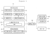
- Fig. 1 is a schematic view of a cooker controlled by a method for controlling a cooker according to an embodiment.
- a heating source 10 for cooking food in a cooking chamber includes an upper heater 11, a halogen heater 12 and a magnetron 13.
- the upper heater 11 is installed in the upper portion of a cooking chamber to provide radiating heat for the cooking chamber.
- a Sheath heater may be used.
- the halogen heater 12 provides radiating heat including light and heat to the cooking chamber.
- the halogen heater 12 provides radiating heat to the cooking chamber through a porous part (not shown) installed in the upper portion of the cooking chamber and formed at the ceiling of the cooking chamber.
- the magnetron 13 oscillates microwave irradiated inward the cooking chamber.
- the heating source 10 further includes a convention heater 15, a convention fan 16 and a convection motor 17.
- the convection heater 15, the convection fan 16 and the convection motor 17 supply convective heat to the cooking chamber. More particularly, since air heated by the convection heater 15 circulates around the cooking chamber by the operation of the convection fan 16, convective heat is supplied to the cooking chamber.
- the convection motor 17 provides a drive force for the operation of the convection fan 16.
- An illumination source 20 illuminates inside the cooking chamber.
- a lamp 21 may be used.
- a steam generator 30 may be provided to supply steam into the cooking chamber.
- the steam generator 30 includes a steam heater 31 and a water supply pump 33.
- the steam heater 31 heats steam water for generating steam supplied to the cooking chamber.
- the water supply pump 33 supplies steam water heated by the steam heater 31.
- a cooling part 40 For the cooling of the heating source 10 and the ventilation of the inside of the cooking chamber, a cooling part 40 may be provided.
- the cooling part 40 includes a cooling fan 41 and a fan motor 43. That is, by means of air flowing by the cooling fan 41 and the fan motor 43, the encapsulating parts of the halogen heater 12, a magnetron 13, a steam heater 31 and a water supply pump 33 may be cooled. Also, in a case the fan motor 43 is driven, the cooling fan 41 operates so that the exterior air may be supplied inside the cooking chamber, and air let inside the cooking chamber may be drained to the exterior of the cooking chamber in a state of containing oil and moisture, etc. existing in the cooking chamber.
- a manipulation signal for the operation of the heating source 10 and the steam generator 30 is input to an input part 50.
- the input part 50 includes a first input part 51 receiving a manipulation signal for cooking food in the cooking chamber and a second input part 53 receiving a manipulation signal for the supply of steam into the cooking chamber.
- the first input part 51 receives a manipulation signal for cooking food in the cooking chamber using at least one of the heating sources 10 and the steam generator 30 (hereinafter, for the convenience of explanation, called a 'manipulation signal (OS0)' and a manipulation signal for cooking food in the cooking chamber using at least one of the heating sources 10 only (hereinafter, for the convenience of explanation, called a 'first manipulation signal (OS1) More particularly, according to the manipulation signal (OSO), the operation start and end time of any one or more of the heating sources 10, or the operation start and end time of any one or more of the heating sources 10 and the operation start and end time of the steam generator 30 is set.
- OSO manipulation signal
- the operation of the steam generator 30 indicates the operation of a steam pump 31 and a water supply pump 33 in an actual meaning.
- the second input part 53 receives an manipulation signal for the start and end of a steam supplying into the cooking chamber among the operation of the heating source 10 (hereinafter, for the convenience of explanation, called 'second and third manipulation signals (OS02)(OS03)'. More particularly, according to the input time of the second manipulation signal (OS2), the operation start time of the steam generator is set. And according to the input time of the third manipulation signal (OS3), the operation end time of the steam generator 30 is set.
- the control part 60 controls the operation of the heating source 10, the illumination source 20, the steam generator 30 and the cooling part 40 according to a manipulation signal inputted into the input part 50. That is, in actuality, the control part 60 controls the operation of the upper heater 11, the halogen heater 12, the convection heater 15, the convection motor 17, the lamp 21, the steam heater 31, the water supply pump 33 and the fan motor 43.
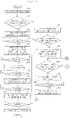
- Fig. 2 is a control flowchart illustrating a method for controlling a cooker according to a first embodiment.
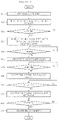
- Fig. 3 is a graph illustrating operating times of components according to the first embodiment.
- the input part 50 receives a manipulation signal (OSO) in operation S11.
- OSO manipulation signal
- the control part 60 controls to initiate the operation of a halogen heater 12, a convection heater 15, a convection motor 17, a lamp 21 and a fan motor 43 at a preset heating start time (TO) according to the manipulation signal (OSO) (S13).
- the halogen heater 12 repeats an ON/OFF action at a preset time interval according to the manipulation signal (OS0).
- the convection heater 15 repeats an ON/OFF action to maintain the cooking chamber temperature at a preset temperature according to the manipulation signal (OSO), and the convection motor repeats an ON/OFF action at a preset time interval according to the manipulation signal (OS0).
- the lamp 21 and the fan motor 43 continue ON action.
- food cooking in the cooking chamber is initiated by the halogen heater 12 and the convection heater 15.
- illumination inside the cooking chamber by the lamp 21, and the cooling of said components and the ventilation of the cooking chamber by the cooling fan 41 are performed.
- the control part 60 determines if they have arrived at a preset steam generating start time (Ts) according to the manipulation signal (OS0) (S15).
- the steam generating start time (Ts) is set as the same point as the heating start time (TO). However, based on food cooked in the cooking chamber, the steam generating start time (Ts) may be set at a different point from the heating start time (TO).
- the control part 60 controls to initiate the operation of the steam heater 13 and the water supply pump 33 (S17).
- steam is supplied into the cooking chamber. More particularly, steam water supplied by the water supply pump 33 is heated by means of the steam heater 31 and then furnished into the cooking chamber in a steam form.
- the halogen heater 12 a phenomenon that steam furnished into the cooking chamber leaks out of the cooking chamber through a porous part, which transfers the light and heat of the halogen heater 12 to the cooking chamber, to cause damage to the halogen heater 12, etc., is prevented.
- steam furnished into the cooking chamber may circulate inside the cooking chamber more effectively.
- the control part 60 determines if they have arrived at a preset water supply end time (Tf1) according to the manipulation signal (OS0) (S19). In operation S19, determined that they have arrived at the water supply end time (Tf1), the control part 60 controls to finish the operation of the water supply pump 33 (S21). Thus, the furnishing of steam water heated by the steam heater 31 is ended. However, since the steam heater 31 continues its operation, steam water pre-supplied by the water supply pump 33 is continuously heated by the steam heater 31 and then furnished into the cooking chamber in a steam form.
- control part 60 determines if a preset steam heating end time (Tf2) according to the manipulation signal (OS0) has arrived after the operation of the water supply pump 33 is ended (S23). In operation S23, determined that the steam heating end time (Tf2) has arrived, the control part 60 controls to finish the operation of the steam heater 31 (S25). Therefore, by completing the operation of the steam heater 31, a steam furnishing into the cooking chamber is ended.
- the control part 60 determines if a preset heating end time (T1) according to the manipulation signal (OS0) has arrived after the operation of the steam heater 31 is ended (S27). In operation S27, determined that the heating end time (T1) has arrived, the control part 60 controls to end the operation of the halogen heater 12, the convection heater 15 and the convection motor 17 and the operation of the lamp 21 (S29). Thus, food cooking in the cooking chamber by the halogen heater 12 and the convection heater 15, and illumination inside the cooking chamber by the lamp 21 are ended.
- the control part 60 determines if a preset fan motor end time (T2) according to the manipulation signal (OSO) has arrived (S31). In operation S31, determined that the fan motor end time (T2) has arrived, the control part 60 controls to end the operation of the fan motor 43. Thus, the cooling of said component and the ventilation of a kitchen by the fan motor 43 is ended.
- Figs. 4 and 5 are control flowcharts illustrating a method for controlling a cooker according to a second embodiment.
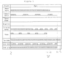
- Figs. 6 and 7 are graphs illustrating operating times of components according to the second embodiment.
- an input part 50 more particularly a first input part 51 receives a first manipulation signal (OS1) (S51).
- OS1 first manipulation signal
- the control part 60 determines if the input part 50, that is a second input part 53, received a second manipulation signal (OS2) for the operation of the steam heater 31 and the water supply pump 33 before a preset heating start time (TO) according to the first manipulation signal (OS1) has arrived (S53).
- control part 60 controls to initiate the operation of the halogen heater 12, the convection heater 15, the convection motor 17, the lamp 21 and the fan motor 43 at the heating start time (TO) (S55).
- control part 60 determines if a preset steam generation start time (Ts) according to the second manipulation signal (OS2) has arrived after the operation of the halogen heater 12, the convection heater 15, the convection motor 17, the lamp 21 and the fan motor 43 was initiated (S57). In operation S57, determined that the steam generation start time (Ts) has arrived, the control part 60 controls to initiate the operation of the steam heater 31 and the water supply pump 33 (S59).
- control part 60 determines if a preset water supply end time (Tf1) according to the second manipulation signal (OS2) has arrived after the operation of the water supply pump 33, was initiated (S61). In operation S61, determined that the water supply end time (Tf1) has arrived, the control part 60 controls to end the operation of the water supply pump 33 (S63).
- the control part 60 determines if a preset steam heating end time (Tf2) according to the second manipulation signal (OS2) has arrived (S65). In operation S65, determined that the steam heating end time (Tf2) has arrived, the control part 60 controls to end the operation of the steam heater 31 (S67).
- control part 60 determines if a preset heating end time (T1) according to the first manipulation signal (OS1) has arrived after the operation of the steam heater 31 was ended (S69). In operation S69, determined that the heating end time (T1) has arrived, the control part 60 controls to end the operation of the halogen heater 12, the convection heater 15 and the convection motor 17 and the operation of the lamp 21 (S71).
- the control part 60 determines if a preset fan motor end time (T2) according to the first manipulation signal has arrived, after the operation of the halogen heater 12, the convection heater 15 and the convection motor 17 and the operation of the lamp 21 was ended (S73). In operation S73, determined that the fan motor end time (T2) has arrived, the control part 60 controls to end the operation of the fan motor 43 (S75). To be sure, a specific operation of the halogen heater 12, the convection heater 15, the convection motor 17, the steam heater 31, the water supply pump 33, the lamp 21 and the fan motor 43 of the operations S51 through S75 of the current embodiment as described above may be substantially the same as that of operations S11 to S33 of the aforementioned first embodiment.
- the first input part 51 receives the manipulation signal (OS0) and in a case the first input part 51 receives the first manipulation signal (OS1) and then the second input part 53 receives the second manipulation signal (OS2) before the heating operation start time (TO) is initiated, a specific operation of the halogen heater 12, the convection heater 15, the convection motor 17, the steam heater 31, the water supply pump 33, the lamp 21 and the fan motor 43 is the same between them.
- the steam generation start time (Ts), the water supply end time (Tf1) and the steam heating end time (Tf2) may be differently set based on the manipulation signal (OS0) and the second manipulation signal (OS2).
- control part 60 determines that the second manipulation signal (OS2) was not inputted in operation S53 before a heating start time (TO) has arrived, the control part 60 controls to initiate the operation of the halogen heater 12, the convection heater 15, the convection motor 17, the lamp 21 and the fan motor 43 at the heating start time (TO) (S77). And, the control part 60 determines again if the second manipulation signal OS2 was inputted before the heating end time (T1) has arrived (S79).
- the control part 60 controls to initiate the operation of the steam heater 31 and the water supply pump 33 at a time (Ts2) when the second manipulation signal (OS2) is input (S81).
- Ts2 time
- the control part 60 determines if the second input part 53 received a third input signal (OS3) for the end of the steam heater 31 and the water supply pump 33 before a point, that is a previous time by a preset remaining water removal time ( ⁇ T) from the heating end time (T1), has arrived (S83).
- the control part 60 controls to end the operation of the water supply pump 33 at a time (Tf3) when the third operation time (OS3) is input (S85). And, when the operation of the water supply pump 33 is ended, the control part 60 determines if the remaining water removal time ( ⁇ T) has elapsed, and controls to end the operation of the steam heater 31 at a time (Tf4) when the remaining water removal time ( ⁇ T) has elapsed from the input time (Tf3) (S87) (S89).
- control unit 60 controls to end the operation of the water supply pump 33 when a previous time by a preset remaining water removal time ( ⁇ T) from the heating end time (T1) arrives (S91) (S93).
- the control part 60 determines if the heating end time (T1) has arrived (S95). Then, determined that the heating end time (T1) has arrived, the control part 60 controls to end the operation of the halogen heater 12, the convection heater 15, the convection motor 17, the steam heater 31 and the lamp 21 (S97). And, the control part 60 performs the operations S73 and S75.
- specific operations of the halogen heater 12, the convection heater 15, the convection motor 17, the steam heater 31, the water supply pump 33, the lamp 21 and the fan motor 43 in operation S51, operation S53, operations S77 through S83, operations S91 through S97, operation S73 and operation S75 could be understood more definitely with reference to Fig. 7 .
Landscapes
- Engineering & Computer Science (AREA)
- Food Science & Technology (AREA)
- Chemical & Material Sciences (AREA)
- Combustion & Propulsion (AREA)
- Mechanical Engineering (AREA)
- General Engineering & Computer Science (AREA)
- Electric Ovens (AREA)
- Electric Stoves And Ranges (AREA)
Description
- The present disclosure relates to a method for controlling a cooker that cooks a food using steam.
- Cookers are home appliances that heat a food using electricity or gas. In recent, cookers in which a steam function for supplying steam into a food is added to supplement moisture which is evaporated during the cooking of the food are being put on the market.
-
US 2004/232140 A1 relates to a high-frequency heating apparatus with steam generation function and a control method thereof. -
JP 2007 303816 A - However, steam supplied into the cooking chamber may be discharged into the cooker.
- Embodiments provide a method of controlling a cooker configured to effectively and safely cook a food using steam.
- According to the invention, a method as defined in claim 1 is provided. Preferred aspects are defined in the dependent claims.
- The details of one or more embodiments are set forth in the accompanying drawings and the description below. Other features will be apparent from the description and drawings, and from the claims.
- According to the embodiments, the food may be further effectively and safely cooked using steam.
- A cooker controlling method as described above expects itself to have the following effects.
- First, in the embodiments, steam is furnished into a cooking chamber while food is cooked in the cooking chamber. Thus, a more effective cooking by steam furnished into a cooking chamber could be performed.
- Also, in the embodiments, a phenomenon that steam furnished into a cooking chamber leaks through a porous part for transferring the energy of a heater installed outside the cooking chamber to the cooking chamber is reduced. Thus, operation reliability of a product may be more improved.
- In addition, in the embodiments, when steam is furnished into a cooking chamber, a convection fan and a convection motor are operated. Thus, steam supplied into the cooking chamber will be more evenly circulated inside the cooking chamber.
- Although embodiments have been described with reference to a number of illustrative embodiments thereof, it should be understood that numerous other modifications and embodiments can be devised by those skilled in the art. More particularly, various variations and modifications are possible in the component parts and/or arrangements of the subject combination arrangement within the scope of the disclosure, the drawings and the appended claims. In addition to variations and modifications in the component parts and/or arrangements, alternative uses will also be apparent to those skilled in the art.
-
-
Fig. 1 is a schematic view of a cooker controlled by a method for controlling a cooker according to an embodiment. -
Fig. 2 is a control flowchart illustrating a method for controlling a cooker according to a first embodiment. -
Fig. 3 is a graph illustrating operating times of components according to the first embodiment. -
Figs. 4 and5 are control flowcharts illustrating a method for controlling a cooker according to a second embodiment (not being claimed). -
Figs. 6 and7 are graphs illustrating operating times of components according to the second embodiment (not being claimed). - Hereinafter, a cooker controlling method according to embodiments will be explained in detail with reference to the accompanying drawings.
-
Fig. 1 is a schematic view of a cooker controlled by a method for controlling a cooker according to an embodiment. - Referring to
Fig. 1 , in the current embodiment, aheating source 10 for cooking food in a cooking chamber includes anupper heater 11, ahalogen heater 12 and amagnetron 13. Theupper heater 11 is installed in the upper portion of a cooking chamber to provide radiating heat for the cooking chamber. As theupper heater 11, a Sheath heater may be used. And, thehalogen heater 12 provides radiating heat including light and heat to the cooking chamber. Thehalogen heater 12 provides radiating heat to the cooking chamber through a porous part (not shown) installed in the upper portion of the cooking chamber and formed at the ceiling of the cooking chamber. Themagnetron 13 oscillates microwave irradiated inward the cooking chamber. - Also, the
heating source 10 further includes aconvention heater 15, aconvention fan 16 and a convection motor 17. Theconvection heater 15, theconvection fan 16 and the convection motor 17 supply convective heat to the cooking chamber. More particularly, since air heated by theconvection heater 15 circulates around the cooking chamber by the operation of theconvection fan 16, convective heat is supplied to the cooking chamber. The convection motor 17 provides a drive force for the operation of theconvection fan 16. - An
illumination source 20 illuminates inside the cooking chamber. As theillumination source 20, alamp 21 may be used. - And, a
steam generator 30 may be provided to supply steam into the cooking chamber. Thesteam generator 30 includes asteam heater 31 and awater supply pump 33. Thesteam heater 31 heats steam water for generating steam supplied to the cooking chamber. Thewater supply pump 33 supplies steam water heated by thesteam heater 31. - For the cooling of the
heating source 10 and the ventilation of the inside of the cooking chamber, acooling part 40 may be provided. Thecooling part 40 includes acooling fan 41 and afan motor 43. That is, by means of air flowing by thecooling fan 41 and thefan motor 43, the encapsulating parts of thehalogen heater 12, amagnetron 13, asteam heater 31 and awater supply pump 33 may be cooled. Also, in a case thefan motor 43 is driven, thecooling fan 41 operates so that the exterior air may be supplied inside the cooking chamber, and air let inside the cooking chamber may be drained to the exterior of the cooking chamber in a state of containing oil and moisture, etc. existing in the cooking chamber. - A manipulation signal for the operation of the
heating source 10 and thesteam generator 30 is input to aninput part 50. Theinput part 50 includes afirst input part 51 receiving a manipulation signal for cooking food in the cooking chamber and a second input part 53 receiving a manipulation signal for the supply of steam into the cooking chamber. Herein, thefirst input part 51 receives a manipulation signal for cooking food in the cooking chamber using at least one of theheating sources 10 and the steam generator 30 (hereinafter, for the convenience of explanation, called a 'manipulation signal (OS0)' and a manipulation signal for cooking food in the cooking chamber using at least one of theheating sources 10 only (hereinafter, for the convenience of explanation, called a 'first manipulation signal (OS1) More particularly, according to the manipulation signal (OSO), the operation start and end time of any one or more of theheating sources 10, or the operation start and end time of any one or more of theheating sources 10 and the operation start and end time of thesteam generator 30 is set. Herein, the operation of thesteam generator 30 indicates the operation of asteam pump 31 and awater supply pump 33 in an actual meaning. And, the second input part 53 receives an manipulation signal for the start and end of a steam supplying into the cooking chamber among the operation of the heating source 10 (hereinafter, for the convenience of explanation, called 'second and third manipulation signals (OS02)(OS03)'. More particularly, according to the input time of the second manipulation signal (OS2), the operation start time of the steam generator is set. And according to the input time of the third manipulation signal (OS3), the operation end time of thesteam generator 30 is set. - The
control part 60 controls the operation of theheating source 10, theillumination source 20, thesteam generator 30 and thecooling part 40 according to a manipulation signal inputted into theinput part 50. That is, in actuality, thecontrol part 60 controls the operation of theupper heater 11, thehalogen heater 12, theconvection heater 15, the convection motor 17, thelamp 21, thesteam heater 31, thewater supply pump 33 and thefan motor 43. - Hereinafter, a method for controlling a cooker according to a first embodiment will be described in detail with reference to the accompanying drawings.
-
Fig. 2 is a control flowchart illustrating a method for controlling a cooker according to a first embodiment.Fig. 3 is a graph illustrating operating times of components according to the first embodiment. - Referring to
Figs. 2 and3 , initially theinput part 50, more particularly, thefirst input part 51 receives a manipulation signal (OSO) in operation S11. - In operation S11, in a case the
first input part 51 receives the manipulation signal (OSO), thecontrol part 60 controls to initiate the operation of ahalogen heater 12, aconvection heater 15, a convection motor 17, alamp 21 and afan motor 43 at a preset heating start time (TO) according to the manipulation signal (OSO) (S13). At this time, thehalogen heater 12 repeats an ON/OFF action at a preset time interval according to the manipulation signal (OS0). And, theconvection heater 15 repeats an ON/OFF action to maintain the cooking chamber temperature at a preset temperature according to the manipulation signal (OSO), and the convection motor repeats an ON/OFF action at a preset time interval according to the manipulation signal (OS0). Thelamp 21 and thefan motor 43 continue ON action. Thus, food cooking in the cooking chamber is initiated by thehalogen heater 12 and theconvection heater 15. Also, illumination inside the cooking chamber by thelamp 21, and the cooling of said components and the ventilation of the cooking chamber by the coolingfan 41 are performed. - And, after the operation of the
halogen heater 12, theconvection heater 15, the convection motor 17, thelamp 21 and thefan motor 43 was initiated, thecontrol part 60 determines if they have arrived at a preset steam generating start time (Ts) according to the manipulation signal (OS0) (S15). In the current embodiment, the steam generating start time (Ts) is set as the same point as the heating start time (TO). However, based on food cooked in the cooking chamber, the steam generating start time (Ts) may be set at a different point from the heating start time (TO). - In operation S15, determined that the steam generating start time (Ts) has arrived, the
control part 60 controls to initiate the operation of thesteam heater 13 and the water supply pump 33 (S17). Thus, by the operation of thesteam heater 31 and thewater supply pump 33, steam is supplied into the cooking chamber. More particularly, steam water supplied by thewater supply pump 33 is heated by means of thesteam heater 31 and then furnished into the cooking chamber in a steam form. Also, by the operation of thehalogen heater 12, a phenomenon that steam furnished into the cooking chamber leaks out of the cooking chamber through a porous part, which transfers the light and heat of thehalogen heater 12 to the cooking chamber, to cause damage to thehalogen heater 12, etc., is prevented. In addition, by circulating air inside the cooking chamber through theconvection fan 16 driven by the operation of the convection motor 17, steam furnished into the cooking chamber may circulate inside the cooking chamber more effectively. - In operation S17, the
steam heater 31 continues an ON action, and thewater supply pump 33 repeats ON/OFF action. - Next, after the operation of the
steam heater 21 and thewater supply pump 33 was initiated, thecontrol part 60 determines if they have arrived at a preset water supply end time (Tf1) according to the manipulation signal (OS0) (S19). In operation S19, determined that they have arrived at the water supply end time (Tf1), thecontrol part 60 controls to finish the operation of the water supply pump 33 (S21). Thus, the furnishing of steam water heated by thesteam heater 31 is ended. However, since thesteam heater 31 continues its operation, steam water pre-supplied by thewater supply pump 33 is continuously heated by thesteam heater 31 and then furnished into the cooking chamber in a steam form. - And, the
control part 60 determines if a preset steam heating end time (Tf2) according to the manipulation signal (OS0) has arrived after the operation of thewater supply pump 33 is ended (S23). In operation S23, determined that the steam heating end time (Tf2) has arrived, thecontrol part 60 controls to finish the operation of the steam heater 31 (S25). Therefore, by completing the operation of thesteam heater 31, a steam furnishing into the cooking chamber is ended. - Next, the
control part 60 determines if a preset heating end time (T1) according to the manipulation signal (OS0) has arrived after the operation of thesteam heater 31 is ended (S27). In operation S27, determined that the heating end time (T1) has arrived, thecontrol part 60 controls to end the operation of thehalogen heater 12, theconvection heater 15 and the convection motor 17 and the operation of the lamp 21 (S29). Thus, food cooking in the cooking chamber by thehalogen heater 12 and theconvection heater 15, and illumination inside the cooking chamber by thelamp 21 are ended. - And, after the operation of the
halogen heater 12, theconvection heater 15 and the convection motor 17 and the operation of thelamp 21 was ended, thecontrol part 60 determines if a preset fan motor end time (T2) according to the manipulation signal (OSO) has arrived (S31). In operation S31, determined that the fan motor end time (T2) has arrived, thecontrol part 60 controls to end the operation of thefan motor 43. Thus, the cooling of said component and the ventilation of a kitchen by thefan motor 43 is ended. - Hereinafter, a method for controlling a cooker according to a second embodiment (not being claimed) will be described in detail with reference to the accompanying drawings.
-
Figs. 4 and5 are control flowcharts illustrating a method for controlling a cooker according to a second embodiment.Figs. 6 and7 are graphs illustrating operating times of components according to the second embodiment. - Referring to
Figs 4 to 7 , initially aninput part 50, more particularly afirst input part 51 receives a first manipulation signal (OS1) (S51). In operation S51, in a case thefirst input part 51 receives the first manipulation signal (OS1), thecontrol part 60 determines if theinput part 50, that is a second input part 53, received a second manipulation signal (OS2) for the operation of thesteam heater 31 and thewater supply pump 33 before a preset heating start time (TO) according to the first manipulation signal (OS1) has arrived (S53). - In operation S53, determined that the second manipulation signal (OS2) was input before the heating start time (TO) has arrived, the
control part 60 controls to initiate the operation of thehalogen heater 12, theconvection heater 15, the convection motor 17, thelamp 21 and thefan motor 43 at the heating start time (TO) (S55). - And, the
control part 60 determines if a preset steam generation start time (Ts) according to the second manipulation signal (OS2) has arrived after the operation of thehalogen heater 12, theconvection heater 15, the convection motor 17, thelamp 21 and thefan motor 43 was initiated (S57). In operation S57, determined that the steam generation start time (Ts) has arrived, thecontrol part 60 controls to initiate the operation of thesteam heater 31 and the water supply pump 33 (S59). - Next, the
control part 60 determines if a preset water supply end time (Tf1) according to the second manipulation signal (OS2) has arrived after the operation of thewater supply pump 33, was initiated (S61). In operation S61, determined that the water supply end time (Tf1) has arrived, thecontrol part 60 controls to end the operation of the water supply pump 33 (S63). - After the operation of the
water supply pump 33 was ended, thecontrol part 60 determines if a preset steam heating end time (Tf2) according to the second manipulation signal (OS2) has arrived (S65). In operation S65, determined that the steam heating end time (Tf2) has arrived, thecontrol part 60 controls to end the operation of the steam heater 31 (S67). - And, the
control part 60 determines if a preset heating end time (T1) according to the first manipulation signal (OS1) has arrived after the operation of thesteam heater 31 was ended (S69). In operation S69, determined that the heating end time (T1) has arrived, thecontrol part 60 controls to end the operation of thehalogen heater 12, theconvection heater 15 and the convection motor 17 and the operation of the lamp 21 (S71). - The
control part 60 determines if a preset fan motor end time (T2) according to the first manipulation signal has arrived, after the operation of thehalogen heater 12, theconvection heater 15 and the convection motor 17 and the operation of thelamp 21 was ended (S73). In operation S73, determined that the fan motor end time (T2) has arrived, thecontrol part 60 controls to end the operation of the fan motor 43 (S75). To be sure, a specific operation of thehalogen heater 12, theconvection heater 15, the convection motor 17, thesteam heater 31, thewater supply pump 33, thelamp 21 and thefan motor 43 of the operations S51 through S75 of the current embodiment as described above may be substantially the same as that of operations S11 to S33 of the aforementioned first embodiment. In other words, in a case thefirst input part 51 receives the manipulation signal (OS0) and in a case thefirst input part 51 receives the first manipulation signal (OS1) and then the second input part 53 receives the second manipulation signal (OS2) before the heating operation start time (TO) is initiated, a specific operation of thehalogen heater 12, theconvection heater 15, the convection motor 17, thesteam heater 31, thewater supply pump 33, thelamp 21 and thefan motor 43 is the same between them. Of course, the steam generation start time (Ts), the water supply end time (Tf1) and the steam heating end time (Tf2) may be differently set based on the manipulation signal (OS0) and the second manipulation signal (OS2). Therefore, in the control according to the operations S51 to S75 of the current embodiment, a specific operation of thehalogen heater 12, thesteam heater 15, the convection motor 17, thesteam heater 31, thewater supply pump 33, thelamp 21 and thefan motor 43 could be understood more definitely with reference toFig. 3 . - In a case the
control part 60 determines that the second manipulation signal (OS2) was not inputted in operation S53 before a heating start time (TO) has arrived, thecontrol part 60 controls to initiate the operation of thehalogen heater 12, theconvection heater 15, the convection motor 17, thelamp 21 and thefan motor 43 at the heating start time (TO) (S77). And, thecontrol part 60 determines again if the second manipulation signal OS2 was inputted before the heating end time (T1) has arrived (S79). - In operation S79, determined that the second manipulation signal (OS2) was inputted before the heating end time (T1) has arrived, the
control part 60 controls to initiate the operation of thesteam heater 31 and thewater supply pump 33 at a time (Ts2) when the second manipulation signal (OS2) is input (S81). When the operation of thesteam heater 31 and thewater supply pump 33 is initiated, thecontrol part 60 determines if the second input part 53 received a third input signal (OS3) for the end of thesteam heater 31 and thewater supply pump 33 before a point, that is a previous time by a preset remaining water removal time (ΔT) from the heating end time (T1), has arrived (S83). - In operation S83, determined that the third manipulation signal (OS3) was input before a previous time by a preset remaining water removal time (ΔT) from the heating end time (T1) has arrived, the
control part 60 controls to end the operation of thewater supply pump 33 at a time (Tf3) when the third operation time (OS3) is input (S85). And, when the operation of thewater supply pump 33 is ended, thecontrol part 60 determines if the remaining water removal time (ΔT) has elapsed, and controls to end the operation of thesteam heater 31 at a time (Tf4) when the remaining water removal time (ΔT) has elapsed from the input time (Tf3) (S87) (S89). - In operation S89, if the operation of the
steam heater 31 is ended, the operations S69 through S75 are performed. As described above, specific operations of theupper heater 11, theconvection heater 15, the convection motor 17, thesteam heater 31, thewater supply pump 33, thelamp 21, and thefan motor 43 in operation S51, operation S53, operations S77 through S83, operations S77 through S89, operation S69 and operation S75 could be understood more definitely with reference toFig. 6 . - In the meantime, in operation S83, in a case the third manipulation signal (OS3) was not inputted before a previous time by a preset remaining water removal time (ΔT) from the heating end time (T1) has arrived, the
control unit 60 controls to end the operation of thewater supply pump 33 when a previous time by a preset remaining water removal time (ΔT) from the heating end time (T1) arrives (S91) (S93). - Next, the
control part 60 determines if the heating end time (T1) has arrived (S95). Then, determined that the heating end time (T1) has arrived, thecontrol part 60 controls to end the operation of thehalogen heater 12, theconvection heater 15, the convection motor 17, thesteam heater 31 and the lamp 21 (S97). And, thecontrol part 60 performs the operations S73 and S75. In the current embodiment, specific operations of thehalogen heater 12, theconvection heater 15, the convection motor 17, thesteam heater 31, thewater supply pump 33, thelamp 21 and thefan motor 43 in operation S51, operation S53, operations S77 through S83, operations S91 through S97, operation S73 and operation S75 could be understood more definitely with reference toFig. 7 . - While it has not been described in detail in the above-mentioned embodiments, in the course of cooking food in the cooking chamber, the operation of the upper heater, the halogen heater, the magnetron, the convection heater, the convection motor, the steam heater and the water supply pump would be ended when the cooking chamber is opened, that is, when a door entering into the cooking chamber is open. Considering it is the fact applying to a general cooker, for example an electronic range, the related detailed description will be omitted.
Claims (11)
- A method for controlling a cooker, comprising:supplying energy into a cooking chamber by at least one heating source (10) at a preset heating start time (T0) based on receiving a manipulation signal (OSO) for cooking food in the cooking chamber using the at least one heating source (10) and a steam generator (30), the preset heating start time (T0) being according to the manipulation signal (OSO);furnishing steam water by a water supply pump (33) for generating steam supplied to the cooking chamber at an arrived preset steam generating start time (Ts) according to the manipulation signal (OSO) andgenerating steam by heating steam water furnished by means of the water supply pump (33) by a steam heater (31) at the arrived preset steam generating start time (Ts);finishing the operation of the water supply pump (33), if a preset water supply end time (Tf1) according to the manipulation signal (OSO) has arrived;finishing the operation of the steam heater (31), if a preset steam heating end time (Tf2) according to the manipulation signal (OSO) has arrived; andfinishing the operation of the at least one heating source (10), if a preset heating end time (T1) according to the manipulation signal (OSO) has arrived,characterized in that the operation of the steam heater (31) and the water supply pump (33) is finished before the operation of the heating source (10) is finished;the operation of the steam heater (31) is finished after the operation of the water supply pump (33) is finished.
- The method according to claim 1, wherein the operation of the steam heater (31) and water supply pump (33) is initiated at the same time as or after the operation of the heating source (10).
- The method according to claim 1, wherein the heating source (10) repeats an ON/OFF action at a preset time interval during a preset operation time.
- The method according to claim 1, wherein the heating source (10) is a halogen heater (12) furnishing light and heat into the cooking chamber.
- The method according to claim 4, wherein the halogen heater (12) transfers light and heat into the cooking chamber through a porous part installed outside the cooking chamber and formed at one side of the cooking chamber.
- The method according to claim 1, wherein the heating source (10) comprises:a convection heater (15);a convection fan (16) circulating air in the cooking chamber to convect heat of the convection heater into the cooking chamber; anda convection motor (17) providing a drive force for the operation of the convection fan (16).
- The method according to claim 6, wherein the convection heater (31) repeats an ON/OFF action to maintain the cooking chamber temperature at a preset cooking temperature during a preset operation time.
- The method according to claim 6, wherein the convection motor (17) repeats an ON/OFF action at a preset time interval during a preset operation time.
- The method according to claim 1, wherein the steam heater (31) continues an ON action during a preset operation time or during an operation time by a user choice.
- The method according to claim 1, wherein the water supply pump (33) repeats a pumping action at a preset time interval during a preset operation time or during an operation time by a user choice.
- The method according to claim 1, wherein the operation of the steam heater (31) and water supply pump (33) is initiated and completed at a respective preset time, separately of a user choice.
Priority Applications (3)
| Application Number | Priority Date | Filing Date | Title |
|---|---|---|---|
| EP18200473.9A EP3459402B1 (en) | 2009-04-06 | 2010-04-06 | Method for controlling cooker |
| EP20160959.1A EP3692867B1 (en) | 2009-04-06 | 2010-04-06 | Method for controlling cooker |
| EP23181938.4A EP4253846A3 (en) | 2009-04-06 | 2010-04-06 | Method for controlling cooker |
Applications Claiming Priority (2)
| Application Number | Priority Date | Filing Date | Title |
|---|---|---|---|
| KR1020090029658A KR101086107B1 (en) | 2009-04-06 | 2009-04-06 | MeThed for controlling cooker |
| PCT/KR2010/002091 WO2010117185A2 (en) | 2009-04-06 | 2010-04-06 | Cooking appliance control method |
Related Child Applications (5)
| Application Number | Title | Priority Date | Filing Date |
|---|---|---|---|
| EP20160959.1A Division EP3692867B1 (en) | 2009-04-06 | 2010-04-06 | Method for controlling cooker |
| EP20160959.1A Division-Into EP3692867B1 (en) | 2009-04-06 | 2010-04-06 | Method for controlling cooker |
| EP23181938.4A Division EP4253846A3 (en) | 2009-04-06 | 2010-04-06 | Method for controlling cooker |
| EP18200473.9A Division EP3459402B1 (en) | 2009-04-06 | 2010-04-06 | Method for controlling cooker |
| EP18200473.9A Division-Into EP3459402B1 (en) | 2009-04-06 | 2010-04-06 | Method for controlling cooker |
Publications (4)
| Publication Number | Publication Date |
|---|---|
| EP2417882A2 EP2417882A2 (en) | 2012-02-15 |
| EP2417882A4 EP2417882A4 (en) | 2016-12-28 |
| EP2417882B1 EP2417882B1 (en) | 2018-11-28 |
| EP2417882B2 true EP2417882B2 (en) | 2022-06-08 |
Family
ID=42936704
Family Applications (4)
| Application Number | Title | Priority Date | Filing Date |
|---|---|---|---|
| EP18200473.9A Active EP3459402B1 (en) | 2009-04-06 | 2010-04-06 | Method for controlling cooker |
| EP10761846.4A Active EP2417882B2 (en) | 2009-04-06 | 2010-04-06 | Cooking appliance control method |
| EP23181938.4A Pending EP4253846A3 (en) | 2009-04-06 | 2010-04-06 | Method for controlling cooker |
| EP20160959.1A Active EP3692867B1 (en) | 2009-04-06 | 2010-04-06 | Method for controlling cooker |
Family Applications Before (1)
| Application Number | Title | Priority Date | Filing Date |
|---|---|---|---|
| EP18200473.9A Active EP3459402B1 (en) | 2009-04-06 | 2010-04-06 | Method for controlling cooker |
Family Applications After (2)
| Application Number | Title | Priority Date | Filing Date |
|---|---|---|---|
| EP23181938.4A Pending EP4253846A3 (en) | 2009-04-06 | 2010-04-06 | Method for controlling cooker |
| EP20160959.1A Active EP3692867B1 (en) | 2009-04-06 | 2010-04-06 | Method for controlling cooker |
Country Status (4)
| Country | Link |
|---|---|
| EP (4) | EP3459402B1 (en) |
| KR (1) | KR101086107B1 (en) |
| ES (1) | ES2806003T3 (en) |
| WO (1) | WO2010117185A2 (en) |
Families Citing this family (5)
| Publication number | Priority date | Publication date | Assignee | Title |
|---|---|---|---|---|
| KR102379989B1 (en) | 2015-01-23 | 2022-03-29 | 발뮤다 가부시키가이샤 | Heating and cooking device |
| KR102556053B1 (en) | 2016-09-09 | 2023-07-18 | 삼성전자주식회사 | Cooking appliance, and control method for the same |
| KR102433053B1 (en) * | 2018-10-23 | 2022-08-16 | 엘지전자 주식회사 | Electronic cooking device with a steam generating apparatus |
| KR102126485B1 (en) * | 2018-10-23 | 2020-06-24 | 엘지전자 주식회사 | Electronic cooking device with a steam generating apparatus |
| CN113842062B (en) * | 2021-09-29 | 2022-11-18 | 杭州老板电器股份有限公司 | Control method and device of humidification system and electric oven with humidification function |
Family Cites Families (8)
| Publication number | Priority date | Publication date | Assignee | Title |
|---|---|---|---|---|
| EP1603365A1 (en) * | 2002-03-12 | 2005-12-07 | Matsushita Electric Industrial Co., Ltd. | High-frequency heating apparatus and control method thereof |
| KR100526210B1 (en) | 2003-10-01 | 2005-11-08 | 삼성전자주식회사 | Steam cooking apparatus |
| KR100624080B1 (en) | 2003-12-09 | 2006-09-19 | 삼성전자주식회사 | Heating cooker |
| JP3682294B1 (en) * | 2004-02-27 | 2005-08-10 | シャープ株式会社 | Steam cooker |
| KR100565535B1 (en) | 2005-01-03 | 2006-03-30 | 엘지전자 주식회사 | Steam supply apparatus for steam oven |
| KR100710218B1 (en) | 2005-12-22 | 2007-04-20 | 엘지전자 주식회사 | Steam oven |
| JP2007303816A (en) * | 2007-07-17 | 2007-11-22 | Matsushita Electric Ind Co Ltd | Cooker |
| US20160033141A1 (en) * | 2014-07-29 | 2016-02-04 | Conair Corporation | Combination heat and steam oven |
-
2009
- 2009-04-06 KR KR1020090029658A patent/KR101086107B1/en active IP Right Grant
-
2010
- 2010-04-06 EP EP18200473.9A patent/EP3459402B1/en active Active
- 2010-04-06 EP EP10761846.4A patent/EP2417882B2/en active Active
- 2010-04-06 EP EP23181938.4A patent/EP4253846A3/en active Pending
- 2010-04-06 EP EP20160959.1A patent/EP3692867B1/en active Active
- 2010-04-06 WO PCT/KR2010/002091 patent/WO2010117185A2/en active Application Filing
- 2010-04-06 ES ES18200473T patent/ES2806003T3/en active Active
Also Published As
| Publication number | Publication date |
|---|---|
| KR101086107B1 (en) | 2011-11-25 |
| EP3692867B1 (en) | 2023-08-16 |
| EP3459402A1 (en) | 2019-03-27 |
| EP2417882B1 (en) | 2018-11-28 |
| EP3692867A1 (en) | 2020-08-12 |
| WO2010117185A3 (en) | 2011-03-10 |
| EP2417882A4 (en) | 2016-12-28 |
| EP4253846A3 (en) | 2023-12-06 |
| EP4253846A2 (en) | 2023-10-04 |
| WO2010117185A2 (en) | 2010-10-14 |
| KR20100111205A (en) | 2010-10-14 |
| EP3459402B1 (en) | 2020-06-03 |
| ES2806003T3 (en) | 2021-02-16 |
| EP2417882A2 (en) | 2012-02-15 |
Similar Documents
| Publication | Publication Date | Title |
|---|---|---|
| EP2417882B2 (en) | Cooking appliance control method | |
| EP2417880B1 (en) | Cooking appliance control method | |
| JP4558543B2 (en) | Cooker | |
| KR101014072B1 (en) | Heating cooker | |
| EP2417883B1 (en) | Method for controlling a cooking apparatus | |
| EP2417884B1 (en) | Cooking appliance control method | |
| KR101152540B1 (en) | Method for cleaning cooking chamber in cooker | |
| KR101596501B1 (en) | Cooker and method for controlling the same | |
| KR101570865B1 (en) | Driving method for convection steam oven | |
| KR101152560B1 (en) | Method for cleaning steam generator for cooker | |
| KR100432751B1 (en) | A heating temperature control method of microwave oven | |
| US20240172778A1 (en) | Cooking appliance for cooking food, cooking method, control unit, and computer program product | |
| EP3804585B1 (en) | Method for operating a cooking oven | |
| KR20080113821A (en) | A microwave oven and a method of controlling the same | |
| JP2010127545A (en) | Cooking device | |
| AU2023201164A1 (en) | Cooking appliance for cooking food, cooking method, control unit, and computer program product | |
| KR200327739Y1 (en) | Convection type micro-wave oven | |
| JP2005061762A (en) | Heating cooker |
Legal Events
| Date | Code | Title | Description |
|---|---|---|---|
| PUAI | Public reference made under article 153(3) epc to a published international application that has entered the european phase |
Free format text: ORIGINAL CODE: 0009012 |
|
| 17P | Request for examination filed |
Effective date: 20111103 |
|
| AK | Designated contracting states |
Kind code of ref document: A2 Designated state(s): AT BE BG CH CY CZ DE DK EE ES FI FR GB GR HR HU IE IS IT LI LT LU LV MC MK MT NL NO PL PT RO SE SI SK SM TR |
|
| DAX | Request for extension of the european patent (deleted) | ||
| REG | Reference to a national code |
Ref country code: DE Ref legal event code: R079 Ref document number: 602010055458 Country of ref document: DE Free format text: PREVIOUS MAIN CLASS: A47J0027080000 Ipc: A47J0027040000 |
|
| A4 | Supplementary search report drawn up and despatched |
Effective date: 20161129 |
|
| RIC1 | Information provided on ipc code assigned before grant |
Ipc: A47J 27/62 20060101ALI20161123BHEP Ipc: A47J 27/04 20060101AFI20161123BHEP Ipc: F24C 3/12 20060101ALI20161123BHEP Ipc: F24C 15/32 20060101ALI20161123BHEP |
|
| STAA | Information on the status of an ep patent application or granted ep patent |
Free format text: STATUS: EXAMINATION IS IN PROGRESS |
|
| 17Q | First examination report despatched |
Effective date: 20170731 |
|
| GRAP | Despatch of communication of intention to grant a patent |
Free format text: ORIGINAL CODE: EPIDOSNIGR1 |
|
| STAA | Information on the status of an ep patent application or granted ep patent |
Free format text: STATUS: GRANT OF PATENT IS INTENDED |
|
| INTG | Intention to grant announced |
Effective date: 20180618 |
|
| GRAS | Grant fee paid |
Free format text: ORIGINAL CODE: EPIDOSNIGR3 |
|
| GRAA | (expected) grant |
Free format text: ORIGINAL CODE: 0009210 |
|
| STAA | Information on the status of an ep patent application or granted ep patent |
Free format text: STATUS: THE PATENT HAS BEEN GRANTED |
|
| AK | Designated contracting states |
Kind code of ref document: B1 Designated state(s): AT BE BG CH CY CZ DE DK EE ES FI FR GB GR HR HU IE IS IT LI LT LU LV MC MK MT NL NO PL PT RO SE SI SK SM TR |
|
| REG | Reference to a national code |
Ref country code: GB Ref legal event code: FG4D |
|
| REG | Reference to a national code |
Ref country code: CH Ref legal event code: EP |
|
| REG | Reference to a national code |
Ref country code: DE Ref legal event code: R096 Ref document number: 602010055458 Country of ref document: DE |
|
| REG | Reference to a national code |
Ref country code: AT Ref legal event code: REF Ref document number: 1069229 Country of ref document: AT Kind code of ref document: T Effective date: 20181215 |
|
| REG | Reference to a national code |
Ref country code: IE Ref legal event code: FG4D |
|
| REG | Reference to a national code |
Ref country code: NL Ref legal event code: MP Effective date: 20181128 |
|
| REG | Reference to a national code |
Ref country code: LT Ref legal event code: MG4D |
|
| REG | Reference to a national code |
Ref country code: AT Ref legal event code: MK05 Ref document number: 1069229 Country of ref document: AT Kind code of ref document: T Effective date: 20181128 |
|
| PG25 | Lapsed in a contracting state [announced via postgrant information from national office to epo] |
Ref country code: BG Free format text: LAPSE BECAUSE OF FAILURE TO SUBMIT A TRANSLATION OF THE DESCRIPTION OR TO PAY THE FEE WITHIN THE PRESCRIBED TIME-LIMIT Effective date: 20190228 Ref country code: NO Free format text: LAPSE BECAUSE OF FAILURE TO SUBMIT A TRANSLATION OF THE DESCRIPTION OR TO PAY THE FEE WITHIN THE PRESCRIBED TIME-LIMIT Effective date: 20190228 Ref country code: LT Free format text: LAPSE BECAUSE OF FAILURE TO SUBMIT A TRANSLATION OF THE DESCRIPTION OR TO PAY THE FEE WITHIN THE PRESCRIBED TIME-LIMIT Effective date: 20181128 Ref country code: FI Free format text: LAPSE BECAUSE OF FAILURE TO SUBMIT A TRANSLATION OF THE DESCRIPTION OR TO PAY THE FEE WITHIN THE PRESCRIBED TIME-LIMIT Effective date: 20181128 Ref country code: IS Free format text: LAPSE BECAUSE OF FAILURE TO SUBMIT A TRANSLATION OF THE DESCRIPTION OR TO PAY THE FEE WITHIN THE PRESCRIBED TIME-LIMIT Effective date: 20190328 Ref country code: AT Free format text: LAPSE BECAUSE OF FAILURE TO SUBMIT A TRANSLATION OF THE DESCRIPTION OR TO PAY THE FEE WITHIN THE PRESCRIBED TIME-LIMIT Effective date: 20181128 Ref country code: ES Free format text: LAPSE BECAUSE OF FAILURE TO SUBMIT A TRANSLATION OF THE DESCRIPTION OR TO PAY THE FEE WITHIN THE PRESCRIBED TIME-LIMIT Effective date: 20181128 Ref country code: LV Free format text: LAPSE BECAUSE OF FAILURE TO SUBMIT A TRANSLATION OF THE DESCRIPTION OR TO PAY THE FEE WITHIN THE PRESCRIBED TIME-LIMIT Effective date: 20181128 Ref country code: HR Free format text: LAPSE BECAUSE OF FAILURE TO SUBMIT A TRANSLATION OF THE DESCRIPTION OR TO PAY THE FEE WITHIN THE PRESCRIBED TIME-LIMIT Effective date: 20181128 |
|
| PG25 | Lapsed in a contracting state [announced via postgrant information from national office to epo] |
Ref country code: PT Free format text: LAPSE BECAUSE OF FAILURE TO SUBMIT A TRANSLATION OF THE DESCRIPTION OR TO PAY THE FEE WITHIN THE PRESCRIBED TIME-LIMIT Effective date: 20190328 Ref country code: SE Free format text: LAPSE BECAUSE OF FAILURE TO SUBMIT A TRANSLATION OF THE DESCRIPTION OR TO PAY THE FEE WITHIN THE PRESCRIBED TIME-LIMIT Effective date: 20181128 Ref country code: GR Free format text: LAPSE BECAUSE OF FAILURE TO SUBMIT A TRANSLATION OF THE DESCRIPTION OR TO PAY THE FEE WITHIN THE PRESCRIBED TIME-LIMIT Effective date: 20190301 |
|
| PG25 | Lapsed in a contracting state [announced via postgrant information from national office to epo] |
Ref country code: NL Free format text: LAPSE BECAUSE OF FAILURE TO SUBMIT A TRANSLATION OF THE DESCRIPTION OR TO PAY THE FEE WITHIN THE PRESCRIBED TIME-LIMIT Effective date: 20181128 |
|
| PG25 | Lapsed in a contracting state [announced via postgrant information from national office to epo] |
Ref country code: PL Free format text: LAPSE BECAUSE OF FAILURE TO SUBMIT A TRANSLATION OF THE DESCRIPTION OR TO PAY THE FEE WITHIN THE PRESCRIBED TIME-LIMIT Effective date: 20181128 Ref country code: CZ Free format text: LAPSE BECAUSE OF FAILURE TO SUBMIT A TRANSLATION OF THE DESCRIPTION OR TO PAY THE FEE WITHIN THE PRESCRIBED TIME-LIMIT Effective date: 20181128 Ref country code: DK Free format text: LAPSE BECAUSE OF FAILURE TO SUBMIT A TRANSLATION OF THE DESCRIPTION OR TO PAY THE FEE WITHIN THE PRESCRIBED TIME-LIMIT Effective date: 20181128 |
|
| REG | Reference to a national code |
Ref country code: DE Ref legal event code: R026 Ref document number: 602010055458 Country of ref document: DE |
|
| PG25 | Lapsed in a contracting state [announced via postgrant information from national office to epo] |
Ref country code: SM Free format text: LAPSE BECAUSE OF FAILURE TO SUBMIT A TRANSLATION OF THE DESCRIPTION OR TO PAY THE FEE WITHIN THE PRESCRIBED TIME-LIMIT Effective date: 20181128 Ref country code: EE Free format text: LAPSE BECAUSE OF FAILURE TO SUBMIT A TRANSLATION OF THE DESCRIPTION OR TO PAY THE FEE WITHIN THE PRESCRIBED TIME-LIMIT Effective date: 20181128 Ref country code: SK Free format text: LAPSE BECAUSE OF FAILURE TO SUBMIT A TRANSLATION OF THE DESCRIPTION OR TO PAY THE FEE WITHIN THE PRESCRIBED TIME-LIMIT Effective date: 20181128 Ref country code: RO Free format text: LAPSE BECAUSE OF FAILURE TO SUBMIT A TRANSLATION OF THE DESCRIPTION OR TO PAY THE FEE WITHIN THE PRESCRIBED TIME-LIMIT Effective date: 20181128 |
|
| PLBI | Opposition filed |
Free format text: ORIGINAL CODE: 0009260 |
|
| PLAX | Notice of opposition and request to file observation + time limit sent |
Free format text: ORIGINAL CODE: EPIDOSNOBS2 |
|
| 26 | Opposition filed |
Opponent name: AURIGIUM LEISCHNER & LUTHE PATENTANWAELTE PARTNERS Effective date: 20190827 |
|
| PG25 | Lapsed in a contracting state [announced via postgrant information from national office to epo] |
Ref country code: SI Free format text: LAPSE BECAUSE OF FAILURE TO SUBMIT A TRANSLATION OF THE DESCRIPTION OR TO PAY THE FEE WITHIN THE PRESCRIBED TIME-LIMIT Effective date: 20181128 |
|
| REG | Reference to a national code |
Ref country code: CH Ref legal event code: PL |
|
| REG | Reference to a national code |
Ref country code: BE Ref legal event code: MM Effective date: 20190430 |
|
| PG25 | Lapsed in a contracting state [announced via postgrant information from national office to epo] |
Ref country code: MC Free format text: LAPSE BECAUSE OF FAILURE TO SUBMIT A TRANSLATION OF THE DESCRIPTION OR TO PAY THE FEE WITHIN THE PRESCRIBED TIME-LIMIT Effective date: 20181128 Ref country code: LU Free format text: LAPSE BECAUSE OF NON-PAYMENT OF DUE FEES Effective date: 20190406 |
|
| PLBB | Reply of patent proprietor to notice(s) of opposition received |
Free format text: ORIGINAL CODE: EPIDOSNOBS3 |
|
| PG25 | Lapsed in a contracting state [announced via postgrant information from national office to epo] |
Ref country code: LI Free format text: LAPSE BECAUSE OF NON-PAYMENT OF DUE FEES Effective date: 20190430 Ref country code: CH Free format text: LAPSE BECAUSE OF NON-PAYMENT OF DUE FEES Effective date: 20190430 |
|
| PG25 | Lapsed in a contracting state [announced via postgrant information from national office to epo] |
Ref country code: BE Free format text: LAPSE BECAUSE OF NON-PAYMENT OF DUE FEES Effective date: 20190430 |
|
| PG25 | Lapsed in a contracting state [announced via postgrant information from national office to epo] |
Ref country code: TR Free format text: LAPSE BECAUSE OF FAILURE TO SUBMIT A TRANSLATION OF THE DESCRIPTION OR TO PAY THE FEE WITHIN THE PRESCRIBED TIME-LIMIT Effective date: 20181128 |
|
| PG25 | Lapsed in a contracting state [announced via postgrant information from national office to epo] |
Ref country code: IE Free format text: LAPSE BECAUSE OF NON-PAYMENT OF DUE FEES Effective date: 20190406 |
|
| PG25 | Lapsed in a contracting state [announced via postgrant information from national office to epo] |
Ref country code: CY Free format text: LAPSE BECAUSE OF FAILURE TO SUBMIT A TRANSLATION OF THE DESCRIPTION OR TO PAY THE FEE WITHIN THE PRESCRIBED TIME-LIMIT Effective date: 20181128 |
|
| PG25 | Lapsed in a contracting state [announced via postgrant information from national office to epo] |
Ref country code: HU Free format text: LAPSE BECAUSE OF FAILURE TO SUBMIT A TRANSLATION OF THE DESCRIPTION OR TO PAY THE FEE WITHIN THE PRESCRIBED TIME-LIMIT; INVALID AB INITIO Effective date: 20100406 Ref country code: MT Free format text: LAPSE BECAUSE OF FAILURE TO SUBMIT A TRANSLATION OF THE DESCRIPTION OR TO PAY THE FEE WITHIN THE PRESCRIBED TIME-LIMIT Effective date: 20181128 |
|
| PUAH | Patent maintained in amended form |
Free format text: ORIGINAL CODE: 0009272 |
|
| STAA | Information on the status of an ep patent application or granted ep patent |
Free format text: STATUS: PATENT MAINTAINED AS AMENDED |
|
| 27A | Patent maintained in amended form |
Effective date: 20220608 |
|
| AK | Designated contracting states |
Kind code of ref document: B2 Designated state(s): AT BE BG CH CY CZ DE DK EE ES FI FR GB GR HR HU IE IS IT LI LT LU LV MC MK MT NL NO PL PT RO SE SI SK SM TR |
|
| REG | Reference to a national code |
Ref country code: DE Ref legal event code: R102 Ref document number: 602010055458 Country of ref document: DE |
|
| PG25 | Lapsed in a contracting state [announced via postgrant information from national office to epo] |
Ref country code: MK Free format text: LAPSE BECAUSE OF FAILURE TO SUBMIT A TRANSLATION OF THE DESCRIPTION OR TO PAY THE FEE WITHIN THE PRESCRIBED TIME-LIMIT Effective date: 20181128 |
|
| PGFP | Annual fee paid to national office [announced via postgrant information from national office to epo] |
Ref country code: FR Payment date: 20230306 Year of fee payment: 14 |
|
| PGFP | Annual fee paid to national office [announced via postgrant information from national office to epo] |
Ref country code: IT Payment date: 20230309 Year of fee payment: 14 |
|
| P01 | Opt-out of the competence of the unified patent court (upc) registered |
Effective date: 20230523 |
|
| PGFP | Annual fee paid to national office [announced via postgrant information from national office to epo] |
Ref country code: DE Payment date: 20230306 Year of fee payment: 14 |
|
| PGFP | Annual fee paid to national office [announced via postgrant information from national office to epo] |
Ref country code: GB Payment date: 20240305 Year of fee payment: 15 |