EP2417882B2 - Regelungsverfahren für eine kochvorrichtung - Google Patents
Regelungsverfahren für eine kochvorrichtung Download PDFInfo
- Publication number
- EP2417882B2 EP2417882B2 EP10761846.4A EP10761846A EP2417882B2 EP 2417882 B2 EP2417882 B2 EP 2417882B2 EP 10761846 A EP10761846 A EP 10761846A EP 2417882 B2 EP2417882 B2 EP 2417882B2
- Authority
- EP
- European Patent Office
- Prior art keywords
- steam
- preset
- heater
- cooking chamber
- time
- Prior art date
- Legal status (The legal status is an assumption and is not a legal conclusion. Google has not performed a legal analysis and makes no representation as to the accuracy of the status listed.)
- Active
Links
Images

Classifications
-
- A—HUMAN NECESSITIES
- A47—FURNITURE; DOMESTIC ARTICLES OR APPLIANCES; COFFEE MILLS; SPICE MILLS; SUCTION CLEANERS IN GENERAL
- A47J—KITCHEN EQUIPMENT; COFFEE MILLS; SPICE MILLS; APPARATUS FOR MAKING BEVERAGES
- A47J27/00—Cooking-vessels
- A47J27/08—Pressure-cookers; Lids or locking devices specially adapted therefor
- A47J27/0802—Control mechanisms for pressure-cookers
-
- F—MECHANICAL ENGINEERING; LIGHTING; HEATING; WEAPONS; BLASTING
- F24—HEATING; RANGES; VENTILATING
- F24C—DOMESTIC STOVES OR RANGES ; DETAILS OF DOMESTIC STOVES OR RANGES, OF GENERAL APPLICATION
- F24C15/00—Details
- F24C15/32—Arrangements of ducts for hot gases, e.g. in or around baking ovens
- F24C15/322—Arrangements of ducts for hot gases, e.g. in or around baking ovens with forced circulation
- F24C15/327—Arrangements of ducts for hot gases, e.g. in or around baking ovens with forced circulation with air moisturising
-
- A—HUMAN NECESSITIES
- A47—FURNITURE; DOMESTIC ARTICLES OR APPLIANCES; COFFEE MILLS; SPICE MILLS; SUCTION CLEANERS IN GENERAL
- A47J—KITCHEN EQUIPMENT; COFFEE MILLS; SPICE MILLS; APPARATUS FOR MAKING BEVERAGES
- A47J27/00—Cooking-vessels
- A47J27/04—Cooking-vessels for cooking food in steam; Devices for extracting fruit juice by means of steam ; Vacuum cooking vessels
-
- A—HUMAN NECESSITIES
- A47—FURNITURE; DOMESTIC ARTICLES OR APPLIANCES; COFFEE MILLS; SPICE MILLS; SUCTION CLEANERS IN GENERAL
- A47J—KITCHEN EQUIPMENT; COFFEE MILLS; SPICE MILLS; APPARATUS FOR MAKING BEVERAGES
- A47J36/00—Parts, details or accessories of cooking-vessels
- A47J36/32—Time-controlled igniting mechanisms or alarm devices
-
- A—HUMAN NECESSITIES
- A47—FURNITURE; DOMESTIC ARTICLES OR APPLIANCES; COFFEE MILLS; SPICE MILLS; SUCTION CLEANERS IN GENERAL
- A47J—KITCHEN EQUIPMENT; COFFEE MILLS; SPICE MILLS; APPARATUS FOR MAKING BEVERAGES
- A47J27/00—Cooking-vessels
- A47J27/04—Cooking-vessels for cooking food in steam; Devices for extracting fruit juice by means of steam ; Vacuum cooking vessels
- A47J2027/043—Cooking-vessels for cooking food in steam; Devices for extracting fruit juice by means of steam ; Vacuum cooking vessels for cooking food in steam
Definitions
- the present disclosure relates to a method for controlling a cooker that cooks a food using steam.
- Cookers are home appliances that heat a food using electricity or gas.
- cookers in which a steam function for supplying steam into a food is added to supplement moisture which is evaporated during the cooking of the food are being put on the market.
- US 2004/232140 A1 relates to a high-frequency heating apparatus with steam generation function and a control method thereof.
- JP 2007 303816 A relates to a cooker, for heating-treating a heated object, by supplying heat from heat sources to a heating chamber for storing the heated object, being provided with a steam generation part provided inside the heating chamber, an evaporation part heating heater, a water supply means, and a steam supply operation means.
- steam supplied into the cooking chamber may be discharged into the cooker.
- Embodiments provide a method of controlling a cooker configured to effectively and safely cook a food using steam.
- the food may be further effectively and safely cooked using steam.
- a cooker controlling method as described above expects itself to have the following effects.
- steam is furnished into a cooking chamber while food is cooked in the cooking chamber.
- a more effective cooking by steam furnished into a cooking chamber could be performed.
- a phenomenon that steam furnished into a cooking chamber leaks through a porous part for transferring the energy of a heater installed outside the cooking chamber to the cooking chamber is reduced.
- operation reliability of a product may be more improved.
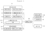
- Fig. 1 is a schematic view of a cooker controlled by a method for controlling a cooker according to an embodiment.
- a heating source 10 for cooking food in a cooking chamber includes an upper heater 11, a halogen heater 12 and a magnetron 13.
- the upper heater 11 is installed in the upper portion of a cooking chamber to provide radiating heat for the cooking chamber.
- a Sheath heater may be used.
- the halogen heater 12 provides radiating heat including light and heat to the cooking chamber.
- the halogen heater 12 provides radiating heat to the cooking chamber through a porous part (not shown) installed in the upper portion of the cooking chamber and formed at the ceiling of the cooking chamber.
- the magnetron 13 oscillates microwave irradiated inward the cooking chamber.
- the heating source 10 further includes a convention heater 15, a convention fan 16 and a convection motor 17.
- the convection heater 15, the convection fan 16 and the convection motor 17 supply convective heat to the cooking chamber. More particularly, since air heated by the convection heater 15 circulates around the cooking chamber by the operation of the convection fan 16, convective heat is supplied to the cooking chamber.
- the convection motor 17 provides a drive force for the operation of the convection fan 16.
- An illumination source 20 illuminates inside the cooking chamber.
- a lamp 21 may be used.
- a steam generator 30 may be provided to supply steam into the cooking chamber.
- the steam generator 30 includes a steam heater 31 and a water supply pump 33.
- the steam heater 31 heats steam water for generating steam supplied to the cooking chamber.
- the water supply pump 33 supplies steam water heated by the steam heater 31.
- a cooling part 40 For the cooling of the heating source 10 and the ventilation of the inside of the cooking chamber, a cooling part 40 may be provided.
- the cooling part 40 includes a cooling fan 41 and a fan motor 43. That is, by means of air flowing by the cooling fan 41 and the fan motor 43, the encapsulating parts of the halogen heater 12, a magnetron 13, a steam heater 31 and a water supply pump 33 may be cooled. Also, in a case the fan motor 43 is driven, the cooling fan 41 operates so that the exterior air may be supplied inside the cooking chamber, and air let inside the cooking chamber may be drained to the exterior of the cooking chamber in a state of containing oil and moisture, etc. existing in the cooking chamber.
- a manipulation signal for the operation of the heating source 10 and the steam generator 30 is input to an input part 50.
- the input part 50 includes a first input part 51 receiving a manipulation signal for cooking food in the cooking chamber and a second input part 53 receiving a manipulation signal for the supply of steam into the cooking chamber.
- the first input part 51 receives a manipulation signal for cooking food in the cooking chamber using at least one of the heating sources 10 and the steam generator 30 (hereinafter, for the convenience of explanation, called a 'manipulation signal (OS0)' and a manipulation signal for cooking food in the cooking chamber using at least one of the heating sources 10 only (hereinafter, for the convenience of explanation, called a 'first manipulation signal (OS1) More particularly, according to the manipulation signal (OSO), the operation start and end time of any one or more of the heating sources 10, or the operation start and end time of any one or more of the heating sources 10 and the operation start and end time of the steam generator 30 is set.
- OSO manipulation signal
- the operation of the steam generator 30 indicates the operation of a steam pump 31 and a water supply pump 33 in an actual meaning.
- the second input part 53 receives an manipulation signal for the start and end of a steam supplying into the cooking chamber among the operation of the heating source 10 (hereinafter, for the convenience of explanation, called 'second and third manipulation signals (OS02)(OS03)'. More particularly, according to the input time of the second manipulation signal (OS2), the operation start time of the steam generator is set. And according to the input time of the third manipulation signal (OS3), the operation end time of the steam generator 30 is set.
- the control part 60 controls the operation of the heating source 10, the illumination source 20, the steam generator 30 and the cooling part 40 according to a manipulation signal inputted into the input part 50. That is, in actuality, the control part 60 controls the operation of the upper heater 11, the halogen heater 12, the convection heater 15, the convection motor 17, the lamp 21, the steam heater 31, the water supply pump 33 and the fan motor 43.
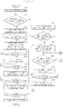
- Fig. 2 is a control flowchart illustrating a method for controlling a cooker according to a first embodiment.
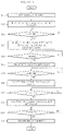
- Fig. 3 is a graph illustrating operating times of components according to the first embodiment.
- the input part 50 receives a manipulation signal (OSO) in operation S11.
- OSO manipulation signal
- the control part 60 controls to initiate the operation of a halogen heater 12, a convection heater 15, a convection motor 17, a lamp 21 and a fan motor 43 at a preset heating start time (TO) according to the manipulation signal (OSO) (S13).
- the halogen heater 12 repeats an ON/OFF action at a preset time interval according to the manipulation signal (OS0).
- the convection heater 15 repeats an ON/OFF action to maintain the cooking chamber temperature at a preset temperature according to the manipulation signal (OSO), and the convection motor repeats an ON/OFF action at a preset time interval according to the manipulation signal (OS0).
- the lamp 21 and the fan motor 43 continue ON action.
- food cooking in the cooking chamber is initiated by the halogen heater 12 and the convection heater 15.
- illumination inside the cooking chamber by the lamp 21, and the cooling of said components and the ventilation of the cooking chamber by the cooling fan 41 are performed.
- the control part 60 determines if they have arrived at a preset steam generating start time (Ts) according to the manipulation signal (OS0) (S15).
- the steam generating start time (Ts) is set as the same point as the heating start time (TO). However, based on food cooked in the cooking chamber, the steam generating start time (Ts) may be set at a different point from the heating start time (TO).
- the control part 60 controls to initiate the operation of the steam heater 13 and the water supply pump 33 (S17).
- steam is supplied into the cooking chamber. More particularly, steam water supplied by the water supply pump 33 is heated by means of the steam heater 31 and then furnished into the cooking chamber in a steam form.
- the halogen heater 12 a phenomenon that steam furnished into the cooking chamber leaks out of the cooking chamber through a porous part, which transfers the light and heat of the halogen heater 12 to the cooking chamber, to cause damage to the halogen heater 12, etc., is prevented.
- steam furnished into the cooking chamber may circulate inside the cooking chamber more effectively.
- the control part 60 determines if they have arrived at a preset water supply end time (Tf1) according to the manipulation signal (OS0) (S19). In operation S19, determined that they have arrived at the water supply end time (Tf1), the control part 60 controls to finish the operation of the water supply pump 33 (S21). Thus, the furnishing of steam water heated by the steam heater 31 is ended. However, since the steam heater 31 continues its operation, steam water pre-supplied by the water supply pump 33 is continuously heated by the steam heater 31 and then furnished into the cooking chamber in a steam form.
- control part 60 determines if a preset steam heating end time (Tf2) according to the manipulation signal (OS0) has arrived after the operation of the water supply pump 33 is ended (S23). In operation S23, determined that the steam heating end time (Tf2) has arrived, the control part 60 controls to finish the operation of the steam heater 31 (S25). Therefore, by completing the operation of the steam heater 31, a steam furnishing into the cooking chamber is ended.
- the control part 60 determines if a preset heating end time (T1) according to the manipulation signal (OS0) has arrived after the operation of the steam heater 31 is ended (S27). In operation S27, determined that the heating end time (T1) has arrived, the control part 60 controls to end the operation of the halogen heater 12, the convection heater 15 and the convection motor 17 and the operation of the lamp 21 (S29). Thus, food cooking in the cooking chamber by the halogen heater 12 and the convection heater 15, and illumination inside the cooking chamber by the lamp 21 are ended.
- the control part 60 determines if a preset fan motor end time (T2) according to the manipulation signal (OSO) has arrived (S31). In operation S31, determined that the fan motor end time (T2) has arrived, the control part 60 controls to end the operation of the fan motor 43. Thus, the cooling of said component and the ventilation of a kitchen by the fan motor 43 is ended.
- Figs. 4 and 5 are control flowcharts illustrating a method for controlling a cooker according to a second embodiment.
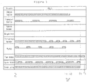
- Figs. 6 and 7 are graphs illustrating operating times of components according to the second embodiment.
- an input part 50 more particularly a first input part 51 receives a first manipulation signal (OS1) (S51).
- OS1 first manipulation signal
- the control part 60 determines if the input part 50, that is a second input part 53, received a second manipulation signal (OS2) for the operation of the steam heater 31 and the water supply pump 33 before a preset heating start time (TO) according to the first manipulation signal (OS1) has arrived (S53).
- control part 60 controls to initiate the operation of the halogen heater 12, the convection heater 15, the convection motor 17, the lamp 21 and the fan motor 43 at the heating start time (TO) (S55).
- control part 60 determines if a preset steam generation start time (Ts) according to the second manipulation signal (OS2) has arrived after the operation of the halogen heater 12, the convection heater 15, the convection motor 17, the lamp 21 and the fan motor 43 was initiated (S57). In operation S57, determined that the steam generation start time (Ts) has arrived, the control part 60 controls to initiate the operation of the steam heater 31 and the water supply pump 33 (S59).
- control part 60 determines if a preset water supply end time (Tf1) according to the second manipulation signal (OS2) has arrived after the operation of the water supply pump 33, was initiated (S61). In operation S61, determined that the water supply end time (Tf1) has arrived, the control part 60 controls to end the operation of the water supply pump 33 (S63).
- the control part 60 determines if a preset steam heating end time (Tf2) according to the second manipulation signal (OS2) has arrived (S65). In operation S65, determined that the steam heating end time (Tf2) has arrived, the control part 60 controls to end the operation of the steam heater 31 (S67).
- control part 60 determines if a preset heating end time (T1) according to the first manipulation signal (OS1) has arrived after the operation of the steam heater 31 was ended (S69). In operation S69, determined that the heating end time (T1) has arrived, the control part 60 controls to end the operation of the halogen heater 12, the convection heater 15 and the convection motor 17 and the operation of the lamp 21 (S71).
- the control part 60 determines if a preset fan motor end time (T2) according to the first manipulation signal has arrived, after the operation of the halogen heater 12, the convection heater 15 and the convection motor 17 and the operation of the lamp 21 was ended (S73). In operation S73, determined that the fan motor end time (T2) has arrived, the control part 60 controls to end the operation of the fan motor 43 (S75). To be sure, a specific operation of the halogen heater 12, the convection heater 15, the convection motor 17, the steam heater 31, the water supply pump 33, the lamp 21 and the fan motor 43 of the operations S51 through S75 of the current embodiment as described above may be substantially the same as that of operations S11 to S33 of the aforementioned first embodiment.
- the first input part 51 receives the manipulation signal (OS0) and in a case the first input part 51 receives the first manipulation signal (OS1) and then the second input part 53 receives the second manipulation signal (OS2) before the heating operation start time (TO) is initiated, a specific operation of the halogen heater 12, the convection heater 15, the convection motor 17, the steam heater 31, the water supply pump 33, the lamp 21 and the fan motor 43 is the same between them.
- the steam generation start time (Ts), the water supply end time (Tf1) and the steam heating end time (Tf2) may be differently set based on the manipulation signal (OS0) and the second manipulation signal (OS2).
- control part 60 determines that the second manipulation signal (OS2) was not inputted in operation S53 before a heating start time (TO) has arrived, the control part 60 controls to initiate the operation of the halogen heater 12, the convection heater 15, the convection motor 17, the lamp 21 and the fan motor 43 at the heating start time (TO) (S77). And, the control part 60 determines again if the second manipulation signal OS2 was inputted before the heating end time (T1) has arrived (S79).
- the control part 60 controls to initiate the operation of the steam heater 31 and the water supply pump 33 at a time (Ts2) when the second manipulation signal (OS2) is input (S81).
- Ts2 time
- the control part 60 determines if the second input part 53 received a third input signal (OS3) for the end of the steam heater 31 and the water supply pump 33 before a point, that is a previous time by a preset remaining water removal time ( ⁇ T) from the heating end time (T1), has arrived (S83).
- the control part 60 controls to end the operation of the water supply pump 33 at a time (Tf3) when the third operation time (OS3) is input (S85). And, when the operation of the water supply pump 33 is ended, the control part 60 determines if the remaining water removal time ( ⁇ T) has elapsed, and controls to end the operation of the steam heater 31 at a time (Tf4) when the remaining water removal time ( ⁇ T) has elapsed from the input time (Tf3) (S87) (S89).
- control unit 60 controls to end the operation of the water supply pump 33 when a previous time by a preset remaining water removal time ( ⁇ T) from the heating end time (T1) arrives (S91) (S93).
- the control part 60 determines if the heating end time (T1) has arrived (S95). Then, determined that the heating end time (T1) has arrived, the control part 60 controls to end the operation of the halogen heater 12, the convection heater 15, the convection motor 17, the steam heater 31 and the lamp 21 (S97). And, the control part 60 performs the operations S73 and S75.
- specific operations of the halogen heater 12, the convection heater 15, the convection motor 17, the steam heater 31, the water supply pump 33, the lamp 21 and the fan motor 43 in operation S51, operation S53, operations S77 through S83, operations S91 through S97, operation S73 and operation S75 could be understood more definitely with reference to Fig. 7 .
Landscapes
- Engineering & Computer Science (AREA)
- Food Science & Technology (AREA)
- Chemical & Material Sciences (AREA)
- Combustion & Propulsion (AREA)
- Mechanical Engineering (AREA)
- General Engineering & Computer Science (AREA)
- Electric Ovens (AREA)
- Electric Stoves And Ranges (AREA)
Claims (11)
- Verfahren zur Steuerung eines Garers, das aufweist:Zuführen von Energie in einen Garraum durch mindestens eine Heizquelle (10) zu einer voreingestellten Heiz-Startzeit (T0) auf der Grundlage des Empfangs eines Bediensignals (OSO) zum Garen von Lebensmitteln im Garraum mithilfe der mindestens einen Heizquelle (10) und eines Dampferzeugers (30), wobei die voreingestellte Heiz-Startzeit (T0) dem Bediensignal (OSO) entspricht,Bereitstellen von Dampfwasser durch eine Wasserzufuhrpumpe (33) zum Erzeugen von Dampf, der dem Garraum zugeführt wird, zu einer erreichten voreingestellten Dampferzeugungs-Startzeit (Ts) entsprechend dem Bediensignal (OSO) undErzeugen von Dampf durch Beheizen von Dampfwasser, das mit Hilfe der Wasserzufuhrpumpe (33) bereitgestellt wird, durch eine Dampfheizung (31) zur erreichten voreingestellten Dampferzeugungs-Startzeit (Ts),Beenden des Betriebs der Wasserzufuhrpumpe (33), wenn eine voreingestellte Wasserzufuhr-Endzeit (Tf1) entsprechend dem Bediensignal (OSO) erreicht ist,Beenden des Betriebs der Dampfheizung (31), wenn eine voreingestellte Dampfheizungs-Endzeit (Tf2) entsprechend dem Bediensignal (OSO) erreicht ist, undBeenden des Betriebs der mindestens einen Heizquelle (10), wenn eine voreingestellte Heizendzeit (T1) entsprechend dem Bediensignal (OSO) erreicht ist;dadurch gekennzeichnet, dass der Betrieb der Dampfheizung (31) und der Wasserzufuhrpumpe (33) beendet wird, bevor der Betrieb der Heizquelle (10) beendet ist;dadurch gekennzeichnet, dass der Betrieb der Dampfheizung (31) beendet wird, nachdem der Betrieb der Wasserzufuhrpumpe (33) beendet ist.
- Verfahren nach Anspruch 1, wobei der Betrieb der Dampfheizung (31) und der Wasserzufuhrpumpe (33) zur gleichen Zeit wie der Betrieb der Heizquelle (10) oder danach initiiert wird.
- Verfahren nach Anspruch 1, wobei die Heizquelle (10) einen EIN/AUS-Vorgang in einem voreingestellten Zeitintervall während einer voreingestellten Betriebszeit wiederholt.
- Verfahren nach Anspruch 1, wobei die Heizquelle (10) eine Halogenheizung (12) ist, die Licht und Wärme im Garraum bereitstellt.
- Verfahren nach Anspruch 4, wobei die Halogenheizung (12) Licht und Wärme in den Garraum über ein poröses Teil überträgt, das außerhalb des Garraums installiert und an einer Seite des Garraums ausgebildet ist.
- Verfahren nach Anspruch 1, wobei die Heizquelle (10) aufweist:eine Konvektionsheizung (15);einen Konvektionsventilator (16), der Luft im Garraum umwälzt, um Wärme der Konvektionsheizung in den Garraum mitzuführen; undeinen Konvektionsmotor (17), der eine Antriebskraft für den Betrieb des Konvektionsventilators (16) bereitstellt.
- Verfahren nach Anspruch 6, wobei die Konvektionsheizung (31) einen EIN/AUS-Vorgang wiederholt, um die Garraumtemperatur auf einer voreingestellten Gartemperatur während einer voreingestellten Betriebszeit zu halten.
- Verfahren nach Anspruch 6, wobei der Konvektionsmotor (17) einen EIN/AUS-Vorgang in einem voreingestellten Zeitintervall während einer voreingestellten Betriebszeit wiederholt.
- Verfahren nach Anspruch 1, wobei die Dampfheizung (31) einen EIN-Vorgang während einer voreingestellten Betriebszeit oder während einer Betriebszeit durch eine Benutzerauswahl fortführt.
- Verfahren nach Anspruch 1, wobei die Wasserzufuhrpumpe (33) einen Pumpvorgang in einem voreingestellten Zeitintervall während einer voreingestellten Betriebszeit oder während einer Betriebszeit durch eine Benutzerauswahl wiederholt.
- Verfahren nach Anspruch 1, wobei der Betrieb der Dampfheizung (31) und der Wasserzufuhrpumpe (33) zu einer jeweiligen voreingestellten Zeit getrennt von einer Benutzerauswahl initiiert und abgeschlossen wird.
Priority Applications (3)
| Application Number | Priority Date | Filing Date | Title |
|---|---|---|---|
| EP20160959.1A EP3692867B1 (de) | 2009-04-06 | 2010-04-06 | Verfahren zur steuerung eines kochers |
| EP23181938.4A EP4253846B1 (de) | 2009-04-06 | 2010-04-06 | Verfahren zur steuerung eines kochers |
| EP18200473.9A EP3459402B1 (de) | 2009-04-06 | 2010-04-06 | Regelungsverfahren für eine kochvorrichtung |
Applications Claiming Priority (2)
| Application Number | Priority Date | Filing Date | Title |
|---|---|---|---|
| KR1020090029658A KR101086107B1 (ko) | 2009-04-06 | 2009-04-06 | 조리기기 제어방법 |
| PCT/KR2010/002091 WO2010117185A2 (ko) | 2009-04-06 | 2010-04-06 | 조리기기 제어방법 |
Related Child Applications (5)
| Application Number | Title | Priority Date | Filing Date |
|---|---|---|---|
| EP18200473.9A Division EP3459402B1 (de) | 2009-04-06 | 2010-04-06 | Regelungsverfahren für eine kochvorrichtung |
| EP18200473.9A Division-Into EP3459402B1 (de) | 2009-04-06 | 2010-04-06 | Regelungsverfahren für eine kochvorrichtung |
| EP23181938.4A Division EP4253846B1 (de) | 2009-04-06 | 2010-04-06 | Verfahren zur steuerung eines kochers |
| EP20160959.1A Division EP3692867B1 (de) | 2009-04-06 | 2010-04-06 | Verfahren zur steuerung eines kochers |
| EP20160959.1A Division-Into EP3692867B1 (de) | 2009-04-06 | 2010-04-06 | Verfahren zur steuerung eines kochers |
Publications (4)
| Publication Number | Publication Date |
|---|---|
| EP2417882A2 EP2417882A2 (de) | 2012-02-15 |
| EP2417882A4 EP2417882A4 (de) | 2016-12-28 |
| EP2417882B1 EP2417882B1 (de) | 2018-11-28 |
| EP2417882B2 true EP2417882B2 (de) | 2022-06-08 |
Family
ID=42936704
Family Applications (4)
| Application Number | Title | Priority Date | Filing Date |
|---|---|---|---|
| EP20160959.1A Active EP3692867B1 (de) | 2009-04-06 | 2010-04-06 | Verfahren zur steuerung eines kochers |
| EP18200473.9A Active EP3459402B1 (de) | 2009-04-06 | 2010-04-06 | Regelungsverfahren für eine kochvorrichtung |
| EP10761846.4A Active EP2417882B2 (de) | 2009-04-06 | 2010-04-06 | Regelungsverfahren für eine kochvorrichtung |
| EP23181938.4A Active EP4253846B1 (de) | 2009-04-06 | 2010-04-06 | Verfahren zur steuerung eines kochers |
Family Applications Before (2)
| Application Number | Title | Priority Date | Filing Date |
|---|---|---|---|
| EP20160959.1A Active EP3692867B1 (de) | 2009-04-06 | 2010-04-06 | Verfahren zur steuerung eines kochers |
| EP18200473.9A Active EP3459402B1 (de) | 2009-04-06 | 2010-04-06 | Regelungsverfahren für eine kochvorrichtung |
Family Applications After (1)
| Application Number | Title | Priority Date | Filing Date |
|---|---|---|---|
| EP23181938.4A Active EP4253846B1 (de) | 2009-04-06 | 2010-04-06 | Verfahren zur steuerung eines kochers |
Country Status (4)
| Country | Link |
|---|---|
| EP (4) | EP3692867B1 (de) |
| KR (1) | KR101086107B1 (de) |
| ES (1) | ES2806003T3 (de) |
| WO (1) | WO2010117185A2 (de) |
Families Citing this family (5)
| Publication number | Priority date | Publication date | Assignee | Title |
|---|---|---|---|---|
| RU2713075C2 (ru) | 2015-01-23 | 2020-02-03 | Балмуда Инк. | Духовой шкаф с парогенератором (варианты) |
| KR102556053B1 (ko) | 2016-09-09 | 2023-07-18 | 삼성전자주식회사 | 조리기기 및 그 제어방법 |
| KR102433053B1 (ko) * | 2018-10-23 | 2022-08-16 | 엘지전자 주식회사 | 스팀 공급 장치가 구비된 전자 조리 기기 |
| KR102126485B1 (ko) * | 2018-10-23 | 2020-06-24 | 엘지전자 주식회사 | 스팀 공급 장치가 구비된 전자 조리 기기 |
| CN113842062B (zh) * | 2021-09-29 | 2022-11-18 | 杭州老板电器股份有限公司 | 加湿系统的控制方法、装置和带加湿功能的电烤箱 |
Family Cites Families (8)
| Publication number | Priority date | Publication date | Assignee | Title |
|---|---|---|---|---|
| EP1684548B1 (de) * | 2002-03-12 | 2008-12-24 | Panasonic Corporation | Hochfrequenzheizvorrichtung und Steuerungsverfahren für dieselbe |
| KR100526210B1 (ko) | 2003-10-01 | 2005-11-08 | 삼성전자주식회사 | 증기조리장치 |
| KR100624080B1 (ko) | 2003-12-09 | 2006-09-19 | 삼성전자주식회사 | 가열조리장치 |
| JP3682294B1 (ja) * | 2004-02-27 | 2005-08-10 | シャープ株式会社 | 蒸気調理器 |
| KR100565535B1 (ko) | 2005-01-03 | 2006-03-30 | 엘지전자 주식회사 | 스팀 오븐의 증기 공급 장치 |
| KR100710218B1 (ko) | 2005-12-22 | 2007-04-20 | 엘지전자 주식회사 | 스팀 오븐 |
| JP2007303816A (ja) * | 2007-07-17 | 2007-11-22 | Matsushita Electric Ind Co Ltd | 加熱調理器 |
| US12281801B2 (en) * | 2014-07-29 | 2025-04-22 | Conair Llc | Combination heat and steam oven |
-
2009
- 2009-04-06 KR KR1020090029658A patent/KR101086107B1/ko active Active
-
2010
- 2010-04-06 EP EP20160959.1A patent/EP3692867B1/de active Active
- 2010-04-06 EP EP18200473.9A patent/EP3459402B1/de active Active
- 2010-04-06 WO PCT/KR2010/002091 patent/WO2010117185A2/ko not_active Ceased
- 2010-04-06 EP EP10761846.4A patent/EP2417882B2/de active Active
- 2010-04-06 ES ES18200473T patent/ES2806003T3/es active Active
- 2010-04-06 EP EP23181938.4A patent/EP4253846B1/de active Active
Also Published As
| Publication number | Publication date |
|---|---|
| EP3692867B1 (de) | 2023-08-16 |
| WO2010117185A3 (ko) | 2011-03-10 |
| EP4253846B1 (de) | 2025-10-29 |
| EP3459402B1 (de) | 2020-06-03 |
| KR101086107B1 (ko) | 2011-11-25 |
| EP4253846A3 (de) | 2023-12-06 |
| EP4253846A2 (de) | 2023-10-04 |
| EP2417882A2 (de) | 2012-02-15 |
| EP3459402A1 (de) | 2019-03-27 |
| KR20100111205A (ko) | 2010-10-14 |
| WO2010117185A2 (ko) | 2010-10-14 |
| EP2417882A4 (de) | 2016-12-28 |
| EP3692867A1 (de) | 2020-08-12 |
| EP2417882B1 (de) | 2018-11-28 |
| ES2806003T3 (es) | 2021-02-16 |
Similar Documents
| Publication | Publication Date | Title |
|---|---|---|
| CN103375826B (zh) | 多功能烹饪设备 | |
| EP2417880B1 (de) | Steuerverfahren für eine kochvorrichtung | |
| EP2417882B2 (de) | Regelungsverfahren für eine kochvorrichtung | |
| US20240172778A1 (en) | Cooking appliance for cooking food, cooking method, control unit, and computer program product | |
| KR101014072B1 (ko) | 가열조리기 | |
| US20260007136A1 (en) | Steam cooking method | |
| EP2417883B1 (de) | Verfahren zur steuerung eines kochgerätes | |
| EP3804585B1 (de) | Verfahren zum betrieb eines kochofens | |
| EP2417884B1 (de) | Steuerverfahren für eine kochvorrichtung | |
| JP4558543B2 (ja) | 加熱調理器 | |
| KR101152540B1 (ko) | 조리기기 세척방법 | |
| KR101596501B1 (ko) | 조리기기 및 그 제어방법 | |
| KR101152560B1 (ko) | 조리기기의 스팀발생장치 세척방법 | |
| KR101570865B1 (ko) | 컨벡션 스팀 오븐기의 구동방법 | |
| KR20080113821A (ko) | 전자레인지 및 그 제어방법 | |
| KR200327739Y1 (ko) | 컨벡션형 전자렌지 | |
| JP2005061762A (ja) | 加熱調理器 |
Legal Events
| Date | Code | Title | Description |
|---|---|---|---|
| PUAI | Public reference made under article 153(3) epc to a published international application that has entered the european phase |
Free format text: ORIGINAL CODE: 0009012 |
|
| 17P | Request for examination filed |
Effective date: 20111103 |
|
| AK | Designated contracting states |
Kind code of ref document: A2 Designated state(s): AT BE BG CH CY CZ DE DK EE ES FI FR GB GR HR HU IE IS IT LI LT LU LV MC MK MT NL NO PL PT RO SE SI SK SM TR |
|
| DAX | Request for extension of the european patent (deleted) | ||
| REG | Reference to a national code |
Ref country code: DE Ref legal event code: R079 Ref document number: 602010055458 Country of ref document: DE Free format text: PREVIOUS MAIN CLASS: A47J0027080000 Ipc: A47J0027040000 |
|
| A4 | Supplementary search report drawn up and despatched |
Effective date: 20161129 |
|
| RIC1 | Information provided on ipc code assigned before grant |
Ipc: A47J 27/62 20060101ALI20161123BHEP Ipc: A47J 27/04 20060101AFI20161123BHEP Ipc: F24C 3/12 20060101ALI20161123BHEP Ipc: F24C 15/32 20060101ALI20161123BHEP |
|
| STAA | Information on the status of an ep patent application or granted ep patent |
Free format text: STATUS: EXAMINATION IS IN PROGRESS |
|
| 17Q | First examination report despatched |
Effective date: 20170731 |
|
| GRAP | Despatch of communication of intention to grant a patent |
Free format text: ORIGINAL CODE: EPIDOSNIGR1 |
|
| STAA | Information on the status of an ep patent application or granted ep patent |
Free format text: STATUS: GRANT OF PATENT IS INTENDED |
|
| INTG | Intention to grant announced |
Effective date: 20180618 |
|
| GRAS | Grant fee paid |
Free format text: ORIGINAL CODE: EPIDOSNIGR3 |
|
| GRAA | (expected) grant |
Free format text: ORIGINAL CODE: 0009210 |
|
| STAA | Information on the status of an ep patent application or granted ep patent |
Free format text: STATUS: THE PATENT HAS BEEN GRANTED |
|
| AK | Designated contracting states |
Kind code of ref document: B1 Designated state(s): AT BE BG CH CY CZ DE DK EE ES FI FR GB GR HR HU IE IS IT LI LT LU LV MC MK MT NL NO PL PT RO SE SI SK SM TR |
|
| REG | Reference to a national code |
Ref country code: GB Ref legal event code: FG4D |
|
| REG | Reference to a national code |
Ref country code: CH Ref legal event code: EP |
|
| REG | Reference to a national code |
Ref country code: DE Ref legal event code: R096 Ref document number: 602010055458 Country of ref document: DE |
|
| REG | Reference to a national code |
Ref country code: AT Ref legal event code: REF Ref document number: 1069229 Country of ref document: AT Kind code of ref document: T Effective date: 20181215 |
|
| REG | Reference to a national code |
Ref country code: IE Ref legal event code: FG4D |
|
| REG | Reference to a national code |
Ref country code: NL Ref legal event code: MP Effective date: 20181128 |
|
| REG | Reference to a national code |
Ref country code: LT Ref legal event code: MG4D |
|
| REG | Reference to a national code |
Ref country code: AT Ref legal event code: MK05 Ref document number: 1069229 Country of ref document: AT Kind code of ref document: T Effective date: 20181128 |
|
| PG25 | Lapsed in a contracting state [announced via postgrant information from national office to epo] |
Ref country code: BG Free format text: LAPSE BECAUSE OF FAILURE TO SUBMIT A TRANSLATION OF THE DESCRIPTION OR TO PAY THE FEE WITHIN THE PRESCRIBED TIME-LIMIT Effective date: 20190228 Ref country code: NO Free format text: LAPSE BECAUSE OF FAILURE TO SUBMIT A TRANSLATION OF THE DESCRIPTION OR TO PAY THE FEE WITHIN THE PRESCRIBED TIME-LIMIT Effective date: 20190228 Ref country code: LT Free format text: LAPSE BECAUSE OF FAILURE TO SUBMIT A TRANSLATION OF THE DESCRIPTION OR TO PAY THE FEE WITHIN THE PRESCRIBED TIME-LIMIT Effective date: 20181128 Ref country code: FI Free format text: LAPSE BECAUSE OF FAILURE TO SUBMIT A TRANSLATION OF THE DESCRIPTION OR TO PAY THE FEE WITHIN THE PRESCRIBED TIME-LIMIT Effective date: 20181128 Ref country code: IS Free format text: LAPSE BECAUSE OF FAILURE TO SUBMIT A TRANSLATION OF THE DESCRIPTION OR TO PAY THE FEE WITHIN THE PRESCRIBED TIME-LIMIT Effective date: 20190328 Ref country code: AT Free format text: LAPSE BECAUSE OF FAILURE TO SUBMIT A TRANSLATION OF THE DESCRIPTION OR TO PAY THE FEE WITHIN THE PRESCRIBED TIME-LIMIT Effective date: 20181128 Ref country code: ES Free format text: LAPSE BECAUSE OF FAILURE TO SUBMIT A TRANSLATION OF THE DESCRIPTION OR TO PAY THE FEE WITHIN THE PRESCRIBED TIME-LIMIT Effective date: 20181128 Ref country code: LV Free format text: LAPSE BECAUSE OF FAILURE TO SUBMIT A TRANSLATION OF THE DESCRIPTION OR TO PAY THE FEE WITHIN THE PRESCRIBED TIME-LIMIT Effective date: 20181128 Ref country code: HR Free format text: LAPSE BECAUSE OF FAILURE TO SUBMIT A TRANSLATION OF THE DESCRIPTION OR TO PAY THE FEE WITHIN THE PRESCRIBED TIME-LIMIT Effective date: 20181128 |
|
| PG25 | Lapsed in a contracting state [announced via postgrant information from national office to epo] |
Ref country code: PT Free format text: LAPSE BECAUSE OF FAILURE TO SUBMIT A TRANSLATION OF THE DESCRIPTION OR TO PAY THE FEE WITHIN THE PRESCRIBED TIME-LIMIT Effective date: 20190328 Ref country code: SE Free format text: LAPSE BECAUSE OF FAILURE TO SUBMIT A TRANSLATION OF THE DESCRIPTION OR TO PAY THE FEE WITHIN THE PRESCRIBED TIME-LIMIT Effective date: 20181128 Ref country code: GR Free format text: LAPSE BECAUSE OF FAILURE TO SUBMIT A TRANSLATION OF THE DESCRIPTION OR TO PAY THE FEE WITHIN THE PRESCRIBED TIME-LIMIT Effective date: 20190301 |
|
| PG25 | Lapsed in a contracting state [announced via postgrant information from national office to epo] |
Ref country code: NL Free format text: LAPSE BECAUSE OF FAILURE TO SUBMIT A TRANSLATION OF THE DESCRIPTION OR TO PAY THE FEE WITHIN THE PRESCRIBED TIME-LIMIT Effective date: 20181128 |
|
| PG25 | Lapsed in a contracting state [announced via postgrant information from national office to epo] |
Ref country code: PL Free format text: LAPSE BECAUSE OF FAILURE TO SUBMIT A TRANSLATION OF THE DESCRIPTION OR TO PAY THE FEE WITHIN THE PRESCRIBED TIME-LIMIT Effective date: 20181128 Ref country code: CZ Free format text: LAPSE BECAUSE OF FAILURE TO SUBMIT A TRANSLATION OF THE DESCRIPTION OR TO PAY THE FEE WITHIN THE PRESCRIBED TIME-LIMIT Effective date: 20181128 Ref country code: DK Free format text: LAPSE BECAUSE OF FAILURE TO SUBMIT A TRANSLATION OF THE DESCRIPTION OR TO PAY THE FEE WITHIN THE PRESCRIBED TIME-LIMIT Effective date: 20181128 |
|
| REG | Reference to a national code |
Ref country code: DE Ref legal event code: R026 Ref document number: 602010055458 Country of ref document: DE |
|
| PG25 | Lapsed in a contracting state [announced via postgrant information from national office to epo] |
Ref country code: SM Free format text: LAPSE BECAUSE OF FAILURE TO SUBMIT A TRANSLATION OF THE DESCRIPTION OR TO PAY THE FEE WITHIN THE PRESCRIBED TIME-LIMIT Effective date: 20181128 Ref country code: EE Free format text: LAPSE BECAUSE OF FAILURE TO SUBMIT A TRANSLATION OF THE DESCRIPTION OR TO PAY THE FEE WITHIN THE PRESCRIBED TIME-LIMIT Effective date: 20181128 Ref country code: SK Free format text: LAPSE BECAUSE OF FAILURE TO SUBMIT A TRANSLATION OF THE DESCRIPTION OR TO PAY THE FEE WITHIN THE PRESCRIBED TIME-LIMIT Effective date: 20181128 Ref country code: RO Free format text: LAPSE BECAUSE OF FAILURE TO SUBMIT A TRANSLATION OF THE DESCRIPTION OR TO PAY THE FEE WITHIN THE PRESCRIBED TIME-LIMIT Effective date: 20181128 |
|
| PLBI | Opposition filed |
Free format text: ORIGINAL CODE: 0009260 |
|
| PLAX | Notice of opposition and request to file observation + time limit sent |
Free format text: ORIGINAL CODE: EPIDOSNOBS2 |
|
| 26 | Opposition filed |
Opponent name: AURIGIUM LEISCHNER & LUTHE PATENTANWAELTE PARTNERS Effective date: 20190827 |
|
| PG25 | Lapsed in a contracting state [announced via postgrant information from national office to epo] |
Ref country code: SI Free format text: LAPSE BECAUSE OF FAILURE TO SUBMIT A TRANSLATION OF THE DESCRIPTION OR TO PAY THE FEE WITHIN THE PRESCRIBED TIME-LIMIT Effective date: 20181128 |
|
| REG | Reference to a national code |
Ref country code: CH Ref legal event code: PL |
|
| REG | Reference to a national code |
Ref country code: BE Ref legal event code: MM Effective date: 20190430 |
|
| PG25 | Lapsed in a contracting state [announced via postgrant information from national office to epo] |
Ref country code: MC Free format text: LAPSE BECAUSE OF FAILURE TO SUBMIT A TRANSLATION OF THE DESCRIPTION OR TO PAY THE FEE WITHIN THE PRESCRIBED TIME-LIMIT Effective date: 20181128 Ref country code: LU Free format text: LAPSE BECAUSE OF NON-PAYMENT OF DUE FEES Effective date: 20190406 |
|
| PLBB | Reply of patent proprietor to notice(s) of opposition received |
Free format text: ORIGINAL CODE: EPIDOSNOBS3 |
|
| PG25 | Lapsed in a contracting state [announced via postgrant information from national office to epo] |
Ref country code: LI Free format text: LAPSE BECAUSE OF NON-PAYMENT OF DUE FEES Effective date: 20190430 Ref country code: CH Free format text: LAPSE BECAUSE OF NON-PAYMENT OF DUE FEES Effective date: 20190430 |
|
| PG25 | Lapsed in a contracting state [announced via postgrant information from national office to epo] |
Ref country code: BE Free format text: LAPSE BECAUSE OF NON-PAYMENT OF DUE FEES Effective date: 20190430 |
|
| PG25 | Lapsed in a contracting state [announced via postgrant information from national office to epo] |
Ref country code: TR Free format text: LAPSE BECAUSE OF FAILURE TO SUBMIT A TRANSLATION OF THE DESCRIPTION OR TO PAY THE FEE WITHIN THE PRESCRIBED TIME-LIMIT Effective date: 20181128 |
|
| PG25 | Lapsed in a contracting state [announced via postgrant information from national office to epo] |
Ref country code: IE Free format text: LAPSE BECAUSE OF NON-PAYMENT OF DUE FEES Effective date: 20190406 |
|
| PG25 | Lapsed in a contracting state [announced via postgrant information from national office to epo] |
Ref country code: CY Free format text: LAPSE BECAUSE OF FAILURE TO SUBMIT A TRANSLATION OF THE DESCRIPTION OR TO PAY THE FEE WITHIN THE PRESCRIBED TIME-LIMIT Effective date: 20181128 |
|
| PG25 | Lapsed in a contracting state [announced via postgrant information from national office to epo] |
Ref country code: HU Free format text: LAPSE BECAUSE OF FAILURE TO SUBMIT A TRANSLATION OF THE DESCRIPTION OR TO PAY THE FEE WITHIN THE PRESCRIBED TIME-LIMIT; INVALID AB INITIO Effective date: 20100406 Ref country code: MT Free format text: LAPSE BECAUSE OF FAILURE TO SUBMIT A TRANSLATION OF THE DESCRIPTION OR TO PAY THE FEE WITHIN THE PRESCRIBED TIME-LIMIT Effective date: 20181128 |
|
| PUAH | Patent maintained in amended form |
Free format text: ORIGINAL CODE: 0009272 |
|
| STAA | Information on the status of an ep patent application or granted ep patent |
Free format text: STATUS: PATENT MAINTAINED AS AMENDED |
|
| 27A | Patent maintained in amended form |
Effective date: 20220608 |
|
| AK | Designated contracting states |
Kind code of ref document: B2 Designated state(s): AT BE BG CH CY CZ DE DK EE ES FI FR GB GR HR HU IE IS IT LI LT LU LV MC MK MT NL NO PL PT RO SE SI SK SM TR |
|
| REG | Reference to a national code |
Ref country code: DE Ref legal event code: R102 Ref document number: 602010055458 Country of ref document: DE |
|
| PG25 | Lapsed in a contracting state [announced via postgrant information from national office to epo] |
Ref country code: MK Free format text: LAPSE BECAUSE OF FAILURE TO SUBMIT A TRANSLATION OF THE DESCRIPTION OR TO PAY THE FEE WITHIN THE PRESCRIBED TIME-LIMIT Effective date: 20181128 |
|
| P01 | Opt-out of the competence of the unified patent court (upc) registered |
Effective date: 20230523 |
|
| PGFP | Annual fee paid to national office [announced via postgrant information from national office to epo] |
Ref country code: FR Payment date: 20250307 Year of fee payment: 16 |
|
| PGFP | Annual fee paid to national office [announced via postgrant information from national office to epo] |
Ref country code: IT Payment date: 20250306 Year of fee payment: 16 Ref country code: GB Payment date: 20250306 Year of fee payment: 16 |
|
| PGFP | Annual fee paid to national office [announced via postgrant information from national office to epo] |
Ref country code: DE Payment date: 20250305 Year of fee payment: 16 |