EP2416618A1 - Relaisstation, basisstation, relaisverfahren und kommunikationsverfahren in einem drahtlosen kommunikationsnetz - Google Patents
Relaisstation, basisstation, relaisverfahren und kommunikationsverfahren in einem drahtlosen kommunikationsnetz Download PDFInfo
- Publication number
- EP2416618A1 EP2416618A1 EP09842622A EP09842622A EP2416618A1 EP 2416618 A1 EP2416618 A1 EP 2416618A1 EP 09842622 A EP09842622 A EP 09842622A EP 09842622 A EP09842622 A EP 09842622A EP 2416618 A1 EP2416618 A1 EP 2416618A1
- Authority
- EP
- European Patent Office
- Prior art keywords
- mac
- mobile stations
- identification information
- relay station
- relay
- Prior art date
- Legal status (The legal status is an assumption and is not a legal conclusion. Google has not performed a legal analysis and makes no representation as to the accuracy of the status listed.)
- Withdrawn
Links
Images


Classifications
-
- H—ELECTRICITY
- H04—ELECTRIC COMMUNICATION TECHNIQUE
- H04B—TRANSMISSION
- H04B7/00—Radio transmission systems, i.e. using radiation field
- H04B7/14—Relay systems
- H04B7/15—Active relay systems
- H04B7/155—Ground-based stations
-
- H—ELECTRICITY
- H04—ELECTRIC COMMUNICATION TECHNIQUE
- H04W—WIRELESS COMMUNICATION NETWORKS
- H04W80/00—Wireless network protocols or protocol adaptations to wireless operation
- H04W80/02—Data link layer protocols
-
- H—ELECTRICITY
- H04—ELECTRIC COMMUNICATION TECHNIQUE
- H04W—WIRELESS COMMUNICATION NETWORKS
- H04W84/00—Network topologies
- H04W84/02—Hierarchically pre-organised networks, e.g. paging networks, cellular networks, WLAN [Wireless Local Area Network] or WLL [Wireless Local Loop]
- H04W84/04—Large scale networks; Deep hierarchical networks
- H04W84/042—Public Land Mobile systems, e.g. cellular systems
- H04W84/047—Public Land Mobile systems, e.g. cellular systems using dedicated repeater stations
Definitions
- the present invention is directed to a relay station, a base station, a relay method and a communication method used in a wireless communications network.
- Mobile communications systems have a problem of a radio wave skip zone, such as a zone suffering severe propagation loss of radio waves due to building shielding and a zone distant from a base station.
- a radio wave skip zone such as a zone suffering severe propagation loss of radio waves due to building shielding and a zone distant from a base station.
- standardization of relay stations is discussed in IEEEB02.16j, IEEE802.16m, LTE-Advanced and the like.
- AF Amplitude-and-Forward
- DF Decode-and-Forward
- One type of the DF strategy is a MAC relay system which restores MAC Service Data Units (SDUs) in a MAC layer which is a data link layer, newly forms a MAC Protocol Data Unit (PDU) in accordance with the size of a Transport Block (TB) at the time of relay, and accordingly changes a transmission scheme, coding and modulation.
- SDUs MAC Service Data Units
- PDU MAC Protocol Data Unit
- the relay station of the MAC relay system is capable of compiling a single MAC_PDU by combining MAC_SDUs of plural UEs at the time of MAC relay and allowing the base station and the relay station to have a step-by-step scheduling function, and has an advantage of achieving a coding gain since the code length becomes long.
- FIG. 1 is a schematic view illustrating a communications system 100, which is a conventional MAC relay system.
- the communications system 100 includes mobile stations UE1 and UE2, a relay station RS and a base station BS.
- a MAC_PDU 11 which is transmitted by the mobile station UE1 to the relay station RS includes a MAC header 111 including identification information (UE_ID) of the mobile station UE1 and UE data 112.
- a MAC_PDU 12 which is transmitted by the mobile station UE2 to the relay station RS includes a MAC header 121 including identification information (UE_ID) of the mobile station UE2 and UE data 122.
- the relay station RS forms a MAC_PDU 13 by multiplexing the MAC_PDU 11 and MAC_PDU 12.
- the MAC_PDU 13 includes a MAC header 131 including identification information (Relay_ID) of the relay station RS, the MAC header 111 and the UE data 112 of the mobile station UE1, and the MAC header 121 and the UE data 122 of the mobile station UE2.
- Relay_ID identification information
- the MAC_PDUs 11, 12 and 13 are respectively transmitted using the same scramble code (SCRAMBLE A).
- the relay station RS includes the identification information of each mobile station UE in a single transport block TB and uses the identification information as a mark of a data unit.
- the data of each UE is identified by the corresponding identification information.
- adding information of the mobile station to the MAC header improves flexibility in control.
- the ID information 131 of the relay station RS is also included in the control information. This increase in the control information results in a reduction in communication efficiency.
- One embodiment of the present invention is a relay station including an extracting unit configured to descramble radio signals transmitted from plural mobile stations and extract identification information of physical layers of the mobile stations; and a multiplexing unit configured to convert the identification information of the physical layers to identification information of MAC layers, which are data link layers, and form a protocol data unit which includes the identification information of the MAC layers in a header and includes service data units of the radio signals transmitted from the mobile stations.
- Another embodiment of the present invention is a relay station including a separating unit configured to convert, to identification information of physical layers of a plurality of mobile stations, identification information of MAC layers included in radio signal transmitted from a base station, which radio signal includes the identification information of the MAC layers, which are data link layers, in a header of the radio signal and includes service data units of radio signals to the mobile stations, and separate a service data unit corresponding to each of the mobile stations.
- One embodiment of the present invention is a relay method for relaying radio signals transmitted from plural mobile stations to a base station.
- the relay method includes extracting identification information of physical layers of the mobile stations from the radio signals; converting the identification information of the physical layers to identification information of MAC layers, which are data link layers; and forming a protocol data unit which includes the identification information of the MAC layers in a header and includes service data units of the radio signals transmitted from the mobile stations.
- Yet another embodiment of the present invention is a relay method for relaying radio signal transmitted from a base station to plural mobile stations.
- the radio signal includes identification information of MAC layers, which are data link layers of the mobile stations, in a header of the radio signal and includes service data units of radio signals transmitted from the mobile stations.
- the relay method includes converting the identification information of the MAC layers to identification information of physical layers; and transmitting to each of the mobile stations, radio signal in which identification information of a physical layer for the mobile station is added to a service data unit corresponding to the mobile station.
- FIG. 2 is a schematic view illustrating a communications system according to one embodiment of the present invention.
- FIG. 3 is a schematic view illustrating processes of a relay station according to the embodiment of the present invention.
- FIG. 4 is a schematic view subsequent to FIG. 3 , illustrating processes of the relay station according to the embodiment of the present invention
- FIG. 5 shows a format of a MAC_PDU after UE multiplexing
- FIG. 6 is a block diagram showing a structural example of a base station
- FIG. 7 is a block diagram showing a structural example of a relay station RS
- FIG. 8 is a block diagram showing a structural example of a mobile station UE
- FIG. 9 is a block diagram showing a structural example of a MAC_SDU separating unit of the relay station of the FIG. 7 ;
- FIG. 10 is a block diagram showing a structural example of a MAC_SDU multiplexing unit of the relay station of FIG. 7 ;
- FIG. 11 is a sequence diagram showing registration processing between the base station and the relay station at the time when the relay station RS starts up;
- FIG. 12 is a block diagram showing a structure of the base station for signaling
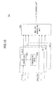
- FIG. 13 is a block diagram showing a structure of the relay station for signaling
- FIG. 14 is a flow diagram showing the operations of the base station, the relay station and the mobile stations for downlink transmission;
- FIG. 15 is a flow diagram showing the operations of the base station, the relay station and the mobile stations for uplink transmission;
- FIG. 16 is a flow diagram showing separation of mobile stations and ID replacement in a MAC layer during the downlink transmission
- FIG. 17 is a flow diagram showing multiplexing of mobile stations and ID replacement in the MAC layer during the uplink transmission
- FIG. 18 is a block diagram showing a structure of a base station-based scheduler
- FIG. 19 illustrates a constraint condition of throughput according to the base station-based scheduler structure shown in FIG. 18 ;
- FIG. 20 shows a protocol structure in the case when the base station-based scheduler is used
- FIG. 21 shows a protocol structure in the case when a relay station distributed scheduler is used.
- FIG. 22 is a block diagram showing a structural example of the relay station in the case where the relay station-distributed scheduler is used.
- LTE Long Term Evolution
- LTE-Advanced Long Term Evolution-Advanced
- FIG. 2 is a schematic view illustrating a communications system 200 according to the embodiment of the present invention.
- the communications system 200 includes mobile stations UE1 and UE2, a relay station RS and a base station BS.
- the mobile station UE1 adds a CRC (Cyclic Redundancy Check) to transmission data, and performs coding and then modulation using a scramble 1 of the mobile station UE1.
- the mobile station UE1 transmits the modulated data as a MAC_PDU 21 from its antenna.
- CRC Cyclic Redundancy Check
- the mobile station UE2 adds a CRC (Cyclic Redundancy Check) to transmission data, and performs coding and then modulation using a scramble 2 of the mobile station UE2.
- the mobile station UE2 transmits the modulated data as a MAC_PDU 22 from its antenna.
- a scramble sequence for each UE is referred to as a PHY_ID.
- communication is performed by replacing a UE_ID with a unique scramble sequence (PHY_ID) corresponding to the UE_ID, and thereby it is possible to reduce the amount of the MAC header to be added.
- PHY_ID unique scramble sequence
- the relay station RS is also regarded as one mobile station UE.
- the relay station RS includes MAC_SDUs of plural mobile stations UE1 and UE2 in a single transport block TB to make its own MAC_SDU.
- the relay station RS then adds a CRC to the MAC_SDU, and performs coding and then modulation using a scramble S (PHY_ID) which indicates the relay station RS.
- the relay station RS transmits the resultant as a MAC_PDU 23 from its antenna.
- Each mobile station and each relay station may perform scrambling before or after the coding process.
- the relay station RS collects header information of all mobile stations UE mapped in the MAC_PDUs to generate a relay station header 231 and adds the relay station header 231 as its MAC header.
- the amount of the MAC header to be added is reduced between each of the mobile stations UE1 and UE2 and the relay station RS, which results in an improvement in usage efficiency of information communication.
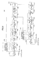
- FIG. 3 is a schematic view illustrating processes of the relay station RS according to one embodiment of the present invention.
- transmission data 311 and 312 transmitted by the mobile stations UE1 and UE2, respectively, have been scrambled using a scramble code specific to each of the mobile stations UE1 and UE2.
- the scramble sequence applied to descrambling may be specified by that the relay station RS preliminarily trains scheduler information.
- a MAC_PDU 321/322 and a PHY_ID 331/332 are obtained for each of the mobile stations UE1 and UE2.
- the MAC_PDUs 321 and 322 and the PHY_IDs 331 and 332 in the MAC layers of the mobile stations UE1 and UE2, respectively, have been obtained.
- Step B For each mobile station UE, conversion is performed from the PHY_IO in the PHY layer to a UE_ID in the MAC layer (Step B).
- the conversion is performed by, for example, searching a table storing PHY_IDs and UE_IDs in association with each other for a UE_ID associated with the PHY_ID in the PHY layer.
- the searched UE ID is embedded in the MAC header so that the identification information of the UE specified by the PHY_ID is not lost.
- a new MAC_PDU is generated by multiplexing MAC_PDUs of the respective UEs (Step C).
- a signal format 41 in which UE_ID information 411 and 412 are respectively inserted in front of the MAC_PDU of a corresponding UE, is obtained.
- the format 41 shown in FIG. 4 since the MAC_PDUs are disposed in accordance with the respective UEs, the MAC headers and MAC_SDUs are provided in a mixed manner.
- the format 41 may be changed to a format 50 of FIG. 5 to make the information easier to transmit by LTE, LTE-Advanced or the like.
- FIG. 5 shows the format 50 of a MAC_PDU after UE multiplexing.
- all the MAC header information is disposed at the beginning.
- the format 50 includes MAC control elements (MAC-CEs) 511 and 512 that are PHY layer control information each corresponding to the mobile stations UE1 and UE2 and inserted in the MAC layers.
- MAC-CEs MAC control elements
- Each MAC control element indicates physical layer control information inserted in a MAC layer.
- LCH Logical CHannel
- C-RNTIs 531 and 532 corresponding to the mobile stations UE1 and UE2, respectively, are UE_IDs managed at the base station and used as IDs in the MAC layers to RRC layers.
- a C-RNTI is a unique identifier that the base station assigns to each user apparatus present in the cell of the base station.
- the format 50 further includes MAC_SDU messages 541 and 542.
- the UE-IDs are mapped in the PHY layers between the mobile stations UE and the relay station RS, which reduces redundancy in the MAC header and improves the wireless frequency usage efficiency.
- the relay station RS includes more information in one transport block TB by combining plural UEs at the time of generating a MAC_PDU, thus achieving a coding gain and improving the effective throughput.
- FIG. 6 is a block diagram showing a structural example of the base station BS.
- Information packets received by the base station BS through a core network are subjected to processes in an upper layer, such as a concealment process and IP header compression, and then stored in L2 buffers 601, each corresponding to a UE which is a transmission destination.
- processes in an upper layer such as a concealment process and IP header compression
- a DL scheduler control signal generating unit 602 generates a control signal which provides each UE a chance to perform transmission according to an appropriate algorithm.
- FIG. 6 shows a flow of information packets transmitted to UEs from the base station BS via the relay station RS.
- the DL scheduler control signal generating unit 602 instructs MAC_PDU generation in consideration of the amount of information packets assigned to the relay station RS and the amount of information packets distributed from the amount assigned to the relay station RS and directed to each UE via the relay station RS.
- a MAC_PDU generating unit 603 reads information packets from the L2 buffer 601 in increments of the amount of transmitted information (transport block TB) in accordance with the control signal of the DL scheduler control signal generating unit 602, and generates a MAC_PDU according to a predetermined format.
- the coding unit 604 performs error-correction coding appropriate for propagation channels of the base station BS and the relay station RS, and sends the resultant to a scrambling unit 605.
- the scrambling unit 605 performs scrambling which indicates that the transmission is directed to the relay station RS and sends the resultant to a modulating unit 606.
- the modulating unit 606 performs appropriate modulations and sends the resultant to a multiplexing unit 607.
- the multiplexing unit 607 multiplexes the control single of the DL scheduler control signal generating unit 602 and a control signal of a UL (uplink) scheduler control signal generating unit 617, and transmits the resultant to a RF transmitting unit 608.
- the RF transmitting unit 608 performs up-conversion to RF (radio frequency), and transmits the resultant from an antenna 610 via a duplexer (DUP) 609.
- DUP duplexer
- a signal received by the antenna 610 is sent to a RF receiving unit 611 via the duplexer 609.
- the RF receiving unit 611 down-converts the received signal to base band frequencies and sends the resultant to a demodulating unit 612.
- the demodulating unit 612 performs appropriate demodulation based on UL schedule information instructed in the past, and sends the resultant to a descrambling unit 613.
- the MAC_SDU extracting unit 615 performs extraction of MAC_SDUs from a correctly received MAC_PDU. Then, the MAC_SDU extracting unit 615 stores information at the right place in a L2 buffer 616 with respect to each UE based on UE_ID information included in the MAC header.
- the information output from the L2 buffer 616 is subjected to processes, such as concealment cancellation and IP header decompression, and then output to the core network (not shown).
- the L2 buffer 616 is provided for each UE; however, only one L2 buffer may be used for plural UEs according to another embodiment of the present invention.
- FIG. 7 is a block diagram showing a structural example of the relay station RS.
- a signal received by an antenna 701 is sent to a RF receiving unit 703 via a duplexer (DUP) 702.
- DUP duplexer
- the RF receiving unit 703 down-converts the received signal to base band frequencies and sends the resultant to a separating unit 704.
- the separating unit 704 reads DL scheduler information and UL scheduler information and sends the information to a DL scheduler control signal extracting unit 705 and a UL scheduler control signal extracting unit 706.
- the RS_PHY_ID descrambling unit 708 performs descrambling in order to determine the transfer made from the base station BS to the relay station RS, and sends the resultant to a decoding unit 709.
- the MAC_SDU separating unit 710 separates MAC_SDUs from the MAC_PDU with reference to MAC header information and performs a process of sorting signals directed to the relay station RS and the respective UEs. At this point, if there is a signal directed to the relay station RS, the MAC_SDU separating unit 710 transfers it to an upper layer.
- a coding unit 711 performs error-correction coding appropriate for a propagation channel of the relay station and each UE on a separated received signal for a corresponding UE, and sends the resultant to a UE_PHY_ID scrambling unit 712.
- the UE_PHY_ID scrambling unit 712 performs scrambling which indicates that the transmission is directed to the UE and sends the resultant to a modulating unit 713.
- the modulating unit 713 performs appropriate modulations and sends the resultant to a multiplexing unit 714.
- the multiplexing unit 714 multiplexes a control signal of the DL scheduler control signal extracting unit 705 and a control signal of the UL scheduler control signal extracting unit 706, and sends the resultant to a RF transmitting unit 715.
- the RF transmitting unit 715 performs up-conversion to RF, and sends the resultant from an antenna 717 via a duplexer (DUP) 716.
- DUP duplexer
- a signal received by the antenna 717 is sent to a RF receiving unit 718 via the duplexer (DUP) 716.
- DUP duplexer
- the RF receiving unit 718 down-converts the received signal to base band frequencies and sends the resultant to a separating unit 719.
- the separating unit 719 performs signal separation for each UE based on UL schedule information instructed in past times, and sends the resultant to a demodulating unit 720.
- the demodulating unit 720 performs demodulations appropriate for each UE, and sends the resultant to a UE_PHY_ID descrambling unit 721.
- the UE_PHY_ID descrambling unit 721 performs descrambling in order to determine the transfer made from a corresponding UE to the relay station, and sends the resultant to a decoding unit 722.
- the decoding unit 722 performs error-correction decoding and sends the resultant to a MAC_PDU multiplexing unit 723. If the CRC check is successful, a MAC_PDU has been correctly received.
- the coding unit 724 After the MAC_PDU multiplexing unit 723 reconstructs the MAC_PDU in this manner, the coding unit 724 performs error-correction coding appropriate for a propagation channel from the relay station RS to the base station BS, and sends the resultant to a RS_PHY_ID scrambling unit 725.
- the RS_PHY_ID scrambling unit 725 performs scrambling which indicates that the information is to be sent from the relay station RS to the base station BS and sends the resultant to a modulating unit 726.
- FIG. 8 is a block diagram showing a structural example of the mobile station UE.
- a signal received by an antenna 801 is sent to a RF receiving unit 803 via a duplexer 802.
- the RF receiving unit 803 down-converts the received signal to base band frequencies and sends the resultant to a separating unit 804.
- the separating unit 804 reads DL scheduler information and UL scheduler information and sends the information to a demodulating unit 807.
- the DL scheduler information and the UL scheduler information are also sent to a DL scheduler control signal extracting unit 805 and a UL scheduler control signal extracting unit 806, respectively.
- the UE_PHY_ID descrambling unit 808 performs descrambling in order to determine the transfer made from the relay station RS to the UE, and sends the resultant to a decoding unit 809.
- a MAC_PDU generating unit 811 generates a MAC_PDU by bundling MAC_SDUs corresponding to the transmittable amount of information instructed by the UL scheduler, and sends the MAC_PDU to a coding unit 812.
- the coding unit 812 performs error-correction coding appropriate for a propagation channel from the mobile station UE to the relay station RS, and sends the resultant to a UE_PHY_ID scrambling unit 813.
- the UE_PHY_ID scrambling unit 813 performs scrambling which indicates that the transmission is directed from the UE to the relay station RS, and sends the resultant to a modulating unit 814.
- FIG. 9 is a block diagram showing a structural example of the MAC_SDU separating unit 710 of the relay station RS shown in FIG. 7 .
- the UE_ID extracting unit 902 extracts UE_IDs included in the MAC header and MAC_PDUs corresponding to the UE_IDs.
- the UE_IDs are sent to an ID converting unit 903 with respect to each UE.
- the MAC_PDUs are sent to a coding unit 711 ( FIG. 7 ) with respect to each UE.
- the MAC_SDU separating unit 710 is able to perform UE separation, which is the reverse of the UE multiplexing described with reference to FIGs. 2 to 5 .
- FIG. 10 is a block diagram showing a structural example of the MAC_SDU multiplexing unit 723 of the relay station RS shown in FIG. 7 .
- the PHY_ID is converted by an ID converting unit 1001 using a conversion table 1002 to a UE_ID which can be recognized in the MAC layer.
- the converted UE_ID and the MAC_POU are input to a MAC_PDU generating unit 1003 with respect to each user.
- the PDU generating unit 1003 uses the format including UE_IDs in the MAC header, described with reference to FIG. 5 to multiplexes all UEs corresponding to the UE_IDs into a single MAC_PDU and sends the MAC_PDU to the coding unit 724.
- the MAC_SDU multiplexing unit 723 is able to perform the UE multiplexing described with reference to FIGs. 2 to 5 .
- the relay station RS for the base station BS, the relay station RS according to the embodiment described above is regarded as a special mobile station UE.
- the relay station RS requests an RRC connection in RACH process to the base station BS when starting up, and sets a relay-station communication configuration.
- FIG. 11 is a sequence diagram showing registration processing performed between the base station BS and the relay station RS at the time when the relay station RS starts up.
- the relay station RS autonomously transmits a RACH preamble to the base station BS (Step S1101).
- the base station BS When detecting the RACH preamble, the base station BS sends back a RACH response in return to the RACH preamble if the traffic allows (Step S1102).
- the relay station RS waits for a RACH response in return to the RACH preamble. If receiving a RACH response within a predetermined period of time, the relay station RS regards it as a transmission permit and transmits an RRC setup Request on which an equivalent to a network ID of a mobile station UE has been added (Step S1103).
- the relay station RS transmits to the base station BS, a RRC setup Request Complete corresponding to the RRC setup Request in the RACH procedure (Step S1105).
- the relay station RS transmits Relay specification notice which indicates that the relay station RS is a relay station (Step S1106).
- the base station BS When receiving the notice, the base station BS sends back a Relay specification response which indicates that the base station BS has recognized the relay station RS as a communication target (Step S1107).
- the base station BS transmits setting information required by the relay station RS (MCS between the base station and the relay station, transmission power of the relay station, a carrier wave frequency after relay and so on) as Relay setup notice (Step S1108).
- the relay station RS starts functioning as a relay station.
- FIG. 12 is a block diagram showing the structure of the base station BS for signaling.
- a signal received by an antenna 1201 is sent to a PHY 1203 via a duplexer 1202.
- the PHY 1203 extracts a MAC_SDU from the received signal and sends the MAC_SDU to an upper layer receiving unit 1204.
- the upper layer receiving unit 1204 extracts a wireless unit control instruction from the received MAC_SDU.
- a Relay specification receiving unit 1205 receives a Relay specification notice message which is sent from the relay station RS after the RACH process.
- the MAC_PDU is converted to a signal format by the PHY 1209 and then transmitted from the antenna 1201 via the duplexer (DUP) 1202.
- DUP duplexer
- a Relay specification transmitting unit 1301 After issuing RRC setup Complete notice to the base station BS following the end of the RACH process, a Relay specification transmitting unit 1301 transmits information indicating that the relay station RS is not a common UE but a relay station.
- the PHY 1306 extracts a MAC_SDU from the received signal and sends the MAC_SDU to an upper layer receiving unit 1307.
- a PHY layer ID is assigned, which is to be used by the assigned relay station in a unique manner, and a PHY_ID for a relay station is applied instead of a PHY_ID for a communication terminal.
- the base station BS takes out transmission data from the L2 buffers, each of which is provided for a different UE (Step S1401), and generates a MAC_PDU in which the transmission data directed to the respective UEs are multiplexed (Step S1402).
- the base station BS generates a PHY from the MAC_PDU (Step S1403) and transmits the PHY as a transmission signal (Step S1404).
- the relay station RS receives the transmission signal transmitted by the base station BS (Step S1405), demodulates, and decodes the transmission signal (Step S1406).
- the relay station RS separates a MAC_SDU with respect to each mobile station UE from the demodulated and decoded data (Step S1407), generates PHYs (Step S1408) and transmits the PHYs as transmission signals (Step S1409).
- FIG. 15 is a flow diagram showing the operations of the mobile stations UE, the relay station RS and the base station BS for uplink transmission.
- Each of the mobile stations UE1-UEn takes out transmission data from its own L2 buffer (Step S1501) and generates a MAC_PDU (Step S1502).
- Each of the mobile stations generates a PHY from the MAC_PDU (Step S1503) and transmits the PHY as a transmission signal (Step S1504).
- the relay station RS receives the transmission signals transmitted by the respective mobile stations UE1-UEn (Step S1505) and obtains MAC_SDUs by demodulating and decoding the PHYs (Step S1506). The relay station RS then multiplexes the obtained MAC_SDUs to generate a MAC_PDU (Step S1507). The relay station RS generates a PHY from the generated MAC_PDU (Step S1508), and transmits the PHY as a transmission signal (Step S1509).
- the base station BS receives the transmission signal from the relay station RS (Step S1510), and demodulates and decodes the PHY (Step S1511). Then, from the demodulated and decoded PHY, the base station BS extracts a MAC_SDU for each mobile station UE, and stores the received data in an L2 buffer provided for the mobile station UE (Step S1513).
- the following gives further details of the operation of the relay station RS for downlink transmission, from the demodulation and decoding of the PHY received from the base station BS (Step S1406 of FIG. 14 ) to the generation of the PHY with respect to each mobile station UE (Step S1408 of FIG. 14 ).
- FIG. 16 is a flow diagram showing separation of mobile stations UEs and ID replacement in the MAC layer during the downlink transmission.
- the relay station RS demodulates and decodes the PHY received from the base station BS (Step S1601) and analyzes the MAC header included in the received data (Step S1602). The relay station RS then counts the number of UE IDs of mobile stations UEs which have been multiplexed onto the received data (Step S1603) and determines the number of the mobile stations UEs multiplexed (Step S1604).
- the following gives further details of the operation of the relay station RS for uplink transmission, from the demodulation and decoding of the PHYs received from the mobile stations UEs (Step S1506 of FIG. 15 ) to the generation of the PHY to be transmitted to the base station (Step S1508 of FIG. 15 ).
- the relay station RS demodulates and decodes a PHY received from each mobile station UE (Step S1701A).
- the relay station RS extracts a MAC_SDU from the received data after demodulation and decoding (Step S1701B).
- the relay station RS performs extraction of a PHY_ID (Step S1701C) and conversion from the PHY_ID to a UE_ID (Step S1701D). These steps S1701A to 1701D are performed for each mobile station UE. (Step S1701).
- the relay station RS generates a MAC_PDU based on the extracted MAC_SDUs and the converted UE_IDs (Step S1702), and generates a PHY from the MAC_PDU (Step S1703).
- FIG. 18 is a block diagram showing the structure of a base station-based scheduler 1800.
- the scheduler performs multiplexing in a two-tier configuration and issues the resultant.
- FIG. 21 shows a protocol structure in the case when the relay station-distributed scheduler is used.
- the relay station RS includes a DL scheduler control signal generating unit 2205 and a UL scheduler control signal generating unit 2206 and performs operation with scheduling independent from the units provided for the communication with the base station BS.
- the present invention is applicable to a relay station, a base station, a relay method and a communication method in a wireless communication network.
Landscapes
- Engineering & Computer Science (AREA)
- Computer Networks & Wireless Communication (AREA)
- Signal Processing (AREA)
- Mobile Radio Communication Systems (AREA)
- Radio Relay Systems (AREA)
Applications Claiming Priority (1)
| Application Number | Priority Date | Filing Date | Title |
|---|---|---|---|
| PCT/JP2009/056676 WO2010113267A1 (ja) | 2009-03-31 | 2009-03-31 | 無線通信ネットワークにおける中継局、基地局、中継方法、及び通信方法 |
Publications (2)
| Publication Number | Publication Date |
|---|---|
| EP2416618A1 true EP2416618A1 (de) | 2012-02-08 |
| EP2416618A4 EP2416618A4 (de) | 2017-01-25 |
Family
ID=42827600
Family Applications (1)
| Application Number | Title | Priority Date | Filing Date |
|---|---|---|---|
| EP09842622.4A Withdrawn EP2416618A4 (de) | 2009-03-31 | 2009-03-31 | Relaisstation, basisstation, relaisverfahren und kommunikationsverfahren in einem drahtlosen kommunikationsnetz |
Country Status (4)
| Country | Link |
|---|---|
| US (1) | US20120008547A1 (de) |
| EP (1) | EP2416618A4 (de) |
| JP (1) | JP5304889B2 (de) |
| WO (1) | WO2010113267A1 (de) |
Cited By (1)
| Publication number | Priority date | Publication date | Assignee | Title |
|---|---|---|---|---|
| CN108886682A (zh) * | 2016-06-03 | 2018-11-23 | Oppo广东移动通信有限公司 | 中继传输的方法和装置 |
Families Citing this family (17)
| Publication number | Priority date | Publication date | Assignee | Title |
|---|---|---|---|---|
| GB2484920B (en) * | 2010-10-25 | 2014-10-08 | Sca Ipla Holdings Inc | Communications systems and method |
| JP5297512B2 (ja) * | 2011-10-06 | 2013-09-25 | 株式会社エヌ・ティ・ティ・ドコモ | 基地局及び通信制御方法 |
| JP2013085031A (ja) * | 2011-10-06 | 2013-05-09 | Ntt Docomo Inc | 基地局及び通信制御方法 |
| US20130155918A1 (en) * | 2011-12-20 | 2013-06-20 | Nokia Siemens Networks Oy | Techniques To Enhance Header Compression Efficiency And Enhance Mobile Node Security |
| TWI572230B (zh) * | 2012-11-23 | 2017-02-21 | Chunghwa Telecom Co Ltd | Energy saving mechanism system and method for wireless relay network |
| KR20140079525A (ko) * | 2012-12-14 | 2014-06-27 | 한국전자통신연구원 | 중계기를 포함한 통신 시스템에서 기지국과 단말의 통신 방법 |
| JP5462396B2 (ja) * | 2013-06-12 | 2014-04-02 | 株式会社Nttドコモ | 基地局及び通信制御方法 |
| JP5696186B2 (ja) * | 2013-08-09 | 2015-04-08 | 株式会社Nttドコモ | 移動局及び無線基地局 |
| KR102139721B1 (ko) * | 2013-08-29 | 2020-07-30 | 삼성전자주식회사 | 다중 경로 프로토콜에서 이중으로 네트워크 코딩을 적용하는 방법 및 그 장치 |
| FR3030992B1 (fr) * | 2014-12-23 | 2016-12-23 | Thales Sa | Systeme et procede de transmission de donnees utilisant conjointement une liaison terrestre et une liaison satellitaire |
| JP6685295B2 (ja) * | 2015-05-22 | 2020-04-22 | 株式会社Nttドコモ | 基地局 |
| CN108138274A (zh) * | 2015-10-08 | 2018-06-08 | 诺维尔里斯公司 | 铝热加工的优化 |
| JP6953584B2 (ja) * | 2016-03-30 | 2021-10-27 | オッポ広東移動通信有限公司Guangdong Oppo Mobile Telecommunications Corp., Ltd. | 中継伝送方法及び装置 |
| JP6731488B2 (ja) * | 2016-03-30 | 2020-07-29 | オッポ広東移動通信有限公司Guangdong Oppo Mobile Telecommunications Corp., Ltd. | 中継伝送方法及び装置 |
| JP6714707B2 (ja) * | 2016-03-30 | 2020-06-24 | オッポ広東移動通信有限公司Guangdong Oppo Mobile Telecommunications Corp., Ltd. | 中継伝送方法 |
| US11177902B2 (en) * | 2017-01-16 | 2021-11-16 | Drexel University | Physical gate based preamble obfuscation for securing wireless communication |
| CN113114328B (zh) * | 2021-03-19 | 2023-03-31 | 中国联合网络通信集团有限公司 | 一种信号中继方法、信号识别方法、装置及设备 |
Family Cites Families (16)
| Publication number | Priority date | Publication date | Assignee | Title |
|---|---|---|---|---|
| CA2456266C (en) * | 2001-08-21 | 2013-06-11 | Nokia Corporation | Transmission of data within a communications network |
| EP1808038B8 (de) * | 2004-10-20 | 2012-05-09 | T-Mobile International AG & Co. KG | Zellular-grossflächen-funkkommunikationssystem mit relay-erweiterten zellen |
| KR20070038657A (ko) * | 2005-10-06 | 2007-04-11 | 삼성전자주식회사 | 다중 홉 릴레이 방식을 사용하는 광대역 무선 접속 통신시스템에서 중계국 기능 교섭 장치 및 방법 |
| WO2007049998A1 (en) * | 2005-10-26 | 2007-05-03 | Telefonaktiebolaget Lm Ericsson (Publ) | Methods and arrangements in a mobile telecommunication network |
| US8489128B2 (en) * | 2005-10-31 | 2013-07-16 | Qualcomm Incorporated | Efficient transmission on a shared data channel for wireless communication |
| CA2631421C (en) * | 2005-12-13 | 2016-08-16 | Lg Electronics Inc. | Communication method using relay station in mobile communication system |
| KR100901137B1 (ko) * | 2006-01-03 | 2009-06-04 | 삼성전자주식회사 | 다중 홉 릴레이 방식 무선 접속 통신시스템에서 연결식별자관리 방법 및 장치 |
| US8576882B2 (en) * | 2006-05-11 | 2013-11-05 | Blackberry Limited | Media access control protocol for multi-hop network systems and method therefore |
| CN101047431B (zh) * | 2006-06-22 | 2011-02-02 | 华为技术有限公司 | 在含有中继站的通信系统中实现混合自动重传的方法 |
| US8468338B2 (en) * | 2006-07-06 | 2013-06-18 | Apple, Inc. | Wireless access point security for multi-hop networks |
| GB2442783A (en) | 2006-10-13 | 2008-04-16 | Fujitsu Ltd | Wireless communication systems |
| JP2008104096A (ja) | 2006-10-20 | 2008-05-01 | Kddi Corp | 無線中継システムおよびそのメッセージ交換方法 |
| EP1916782A1 (de) * | 2006-10-26 | 2008-04-30 | Nortel Networks Limited | Rahmenstruktur für ein drahtloses Mehrsprungsystem |
| US8717964B2 (en) * | 2007-03-09 | 2014-05-06 | Motorola Solutions, Inc. | Wireless wide-area communication network multihop relay station management |
| WO2009022855A2 (en) * | 2007-08-13 | 2009-02-19 | Lg Electronics Inc. | Method for transmitting voip packet |
| EP2043391A1 (de) * | 2007-09-25 | 2009-04-01 | Nokia Siemens Networks Oy | UE-ID-Auslassung in einem verbesserten RACH-Vorgang |
-
2009
- 2009-03-31 EP EP09842622.4A patent/EP2416618A4/de not_active Withdrawn
- 2009-03-31 WO PCT/JP2009/056676 patent/WO2010113267A1/ja not_active Ceased
- 2009-03-31 JP JP2011506892A patent/JP5304889B2/ja not_active Expired - Fee Related
-
2011
- 2011-09-22 US US13/240,491 patent/US20120008547A1/en not_active Abandoned
Non-Patent Citations (1)
| Title |
|---|
| See references of WO2010113267A1 * |
Cited By (2)
| Publication number | Priority date | Publication date | Assignee | Title |
|---|---|---|---|---|
| CN108886682A (zh) * | 2016-06-03 | 2018-11-23 | Oppo广东移动通信有限公司 | 中继传输的方法和装置 |
| US11405773B2 (en) | 2016-06-03 | 2022-08-02 | Guangdong Oppo Mobile Telecommunications Corp., Ltd. | Method and device for relay transmission |
Also Published As
| Publication number | Publication date |
|---|---|
| US20120008547A1 (en) | 2012-01-12 |
| EP2416618A4 (de) | 2017-01-25 |
| JPWO2010113267A1 (ja) | 2012-10-04 |
| JP5304889B2 (ja) | 2013-10-02 |
| WO2010113267A1 (ja) | 2010-10-07 |
Similar Documents
| Publication | Publication Date | Title |
|---|---|---|
| EP2416618A1 (de) | Relaisstation, basisstation, relaisverfahren und kommunikationsverfahren in einem drahtlosen kommunikationsnetz | |
| JP7768178B2 (ja) | カバレージ内およびカバレージ外シナリオでのサイドリンクのharq | |
| US8451769B2 (en) | Method of receiving message in communication system using relay process being limited to wireless interface and apparatus of the same | |
| EP2335432B1 (de) | Verfahren und Anordnung in einem Telekommunikationssystem | |
| US8755324B2 (en) | Allocating backhaul resources | |
| CN101346906B (zh) | 随机接入过程处理方法 | |
| KR100884699B1 (ko) | 투명 릴레이를 위한 방법 및 장치 | |
| US8345587B2 (en) | Relay station, base station and method for extending a coverage area of a base station in a radio network | |
| EP2204925B1 (de) | Verfahren zur übertragung von rundfunknachrichten in einem mehrsprung relaisnetz | |
| CN110692279A (zh) | 无线通信系统中的终端的d2d操作方法及其终端 | |
| US20170230941A1 (en) | Method and device for allocating resources in wireless communication system supporting d2d communication | |
| CN101873609B (zh) | 一种中继系统中的数据发送方法和装置 | |
| CN102045773B (zh) | 中继节点的数据传输冲突的处理方法和装置 | |
| KR20140056344A (ko) | 중계 장치 및 방법 | |
| WO2007069848A2 (en) | Communication method using relay station in mobile communication system | |
| WO2011077066A1 (en) | Transmission in a communication system using relay nodes | |
| US20150312909A1 (en) | Radio communication system, base station, relay station, and radio communication method | |
| WO2008044318A1 (en) | Radio base station, relay station, and communication control method | |
| KR101404677B1 (ko) | 중계기를 기반으로 하는 무선통신 시스템에서 무선자원을효율적으로 이용하기 위한 방법 및 장치 | |
| CN109963283B (zh) | 一种lte小区的实现方法 | |
| KR20170112773A (ko) | 차량 통신을 지원하는 무선통신 시스템에서 스케줄링 정보 보고 방법 및 장치, 그리고 무선자원 스케줄링 방법 및 장치 | |
| CN112153666B (zh) | 通信方法、中继设备、宿主基站及计算机存储介质 | |
| US8605641B2 (en) | Method of supporting a multicast and broadcast service in wireless access system supporting relay | |
| KR101208521B1 (ko) | 이동통신 시스템에서의 중계국 영역 지정 방법 및 검색방법 | |
| CN102036383A (zh) | 下行数据发送方法及系统 |
Legal Events
| Date | Code | Title | Description |
|---|---|---|---|
| PUAI | Public reference made under article 153(3) epc to a published international application that has entered the european phase |
Free format text: ORIGINAL CODE: 0009012 |
|
| 17P | Request for examination filed |
Effective date: 20111024 |
|
| AK | Designated contracting states |
Kind code of ref document: A1 Designated state(s): AT BE BG CH CY CZ DE DK EE ES FI FR GB GR HR HU IE IS IT LI LT LU LV MC MK MT NL NO PL PT RO SE SI SK TR |
|
| DAX | Request for extension of the european patent (deleted) | ||
| RA4 | Supplementary search report drawn up and despatched (corrected) |
Effective date: 20161222 |
|
| RIC1 | Information provided on ipc code assigned before grant |
Ipc: H04W 88/00 20090101AFI20161216BHEP Ipc: H04B 7/155 20060101ALI20161216BHEP |
|
| 17Q | First examination report despatched |
Effective date: 20180305 |
|
| STAA | Information on the status of an ep patent application or granted ep patent |
Free format text: STATUS: THE APPLICATION HAS BEEN WITHDRAWN |
|
| 18W | Application withdrawn |
Effective date: 20180601 |