WO2010113267A1 - 無線通信ネットワークにおける中継局、基地局、中継方法、及び通信方法 - Google Patents
無線通信ネットワークにおける中継局、基地局、中継方法、及び通信方法 Download PDFInfo
- Publication number
- WO2010113267A1 WO2010113267A1 PCT/JP2009/056676 JP2009056676W WO2010113267A1 WO 2010113267 A1 WO2010113267 A1 WO 2010113267A1 JP 2009056676 W JP2009056676 W JP 2009056676W WO 2010113267 A1 WO2010113267 A1 WO 2010113267A1
- Authority
- WO
- WIPO (PCT)
- Prior art keywords
- station
- mac
- relay
- identification information
- unit
- Prior art date
Links
Images


Classifications
-
- H—ELECTRICITY
- H04—ELECTRIC COMMUNICATION TECHNIQUE
- H04B—TRANSMISSION
- H04B7/00—Radio transmission systems, i.e. using radiation field
- H04B7/14—Relay systems
- H04B7/15—Active relay systems
- H04B7/155—Ground-based stations
-
- H—ELECTRICITY
- H04—ELECTRIC COMMUNICATION TECHNIQUE
- H04W—WIRELESS COMMUNICATION NETWORKS
- H04W80/00—Wireless network protocols or protocol adaptations to wireless operation
- H04W80/02—Data link layer protocols
-
- H—ELECTRICITY
- H04—ELECTRIC COMMUNICATION TECHNIQUE
- H04W—WIRELESS COMMUNICATION NETWORKS
- H04W84/00—Network topologies
- H04W84/02—Hierarchically pre-organised networks, e.g. paging networks, cellular networks, WLAN [Wireless Local Area Network] or WLL [Wireless Local Loop]
- H04W84/04—Large scale networks; Deep hierarchical networks
- H04W84/042—Public Land Mobile systems, e.g. cellular systems
- H04W84/047—Public Land Mobile systems, e.g. cellular systems using dedicated repeater stations
Definitions
- the present invention relates to a relay station, a base station, a relay method, and a communication method in a wireless communication network.
- AF Amplitude and Forward
- DF Decode and Forward
- the MAC service data unit (SDU (Service Data Unit)) is restored in the MAC layer that is the data link layer, and is matched to the size of the transport block (TB (Transport Block)) during relaying
- SDU Service Data Unit
- TB Transport Block
- PDU Protocol Data Unit
- the mobile station UE ID is assigned in the MAC layer in consideration of multiplexing of the mobile station UE and separation into each mobile station UE, and the UE management is clearly defined. We are trying to make it.
- the MAC relay type relay station can combine the MAC_SDUs of a plurality of UEs into a single MAC_PDU at the time of MAC relay in this way, and can provide a stepwise scheduling function between the base station and the relay station. There is a feature that a coding gain can be obtained by increasing the length.
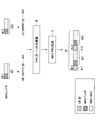
- FIG. 1 is a schematic diagram showing a conventional MAC relay type communication system 100.
- the communication system 100 includes mobile stations UE1 and UE2, a relay station RS, and a base station BS.
- the MAC_PDU 11 transmitted from the mobile station UE1 to the relay station RS includes a MAC header 111 including UE1 identification information (UE_ID) and UE data 112. Further, the MAC_PDU 12 transmitted from the mobile station UE2 to the relay station RS includes a MAC header 121 including identification information (UE_ID) of the mobile station UE2 and UE data 122.
- UE_ID UE1 identification information
- UE_ID identification information
- the relay station RS configures the MAC_PDU 13 by multiplexing these.
- the MAC_PDU 13 includes a MAC header 131 including identification information (Relay_ID) of the relay station RS, a MAC header 111 and UE data 112 of UE1, and a MAC header 121 and UE data 122 of UE2.
- Relay_ID identification information
- MAC_PDUs 11, 12, and 13 are all transmitted with the same scramble code (scramble A).
- the relay station RS includes the identification information of each mobile station UE in one transport block TB, and uses the identification information as a data unit mark.
- the data of each UE is identified by identification information.
- the degree of freedom of control is improved by adding mobile station information to the MAC header.
- the ID information 131 of the relay station RS is included in the control information together with the ID information 111 and 121 of the mobile station UE. For this reason, there has been a problem that communication efficiency is reduced due to an increase in control information.
- the relay station includes an extraction unit that descrambles signals from a plurality of mobile stations and extracts identification information of a physical layer of the mobile station, and a MAC layer that is a data link layer that identifies the identification information of the physical layer And a multiplexing unit that constitutes a protocol data unit including MAC layer identification information of the plurality of mobile stations in a header and including service data units of signals from the plurality of mobile stations.
- a relay station includes identification information of a MAC layer that is a data link layer of a plurality of mobile stations in a header, and is included in a signal from a base station that includes service data units of signals from the plurality of mobile stations.
- a separation unit that converts the identification information of the MAC layer into the identification information of the physical layer and separates the service data unit corresponding to each mobile station.
- a relay method for relaying signals from a plurality of mobile stations to a base station includes extracting physical layer identification information of the mobile station from the signals, and identifying the physical layer identification information in a data link layer. Converting into identification information of a certain MAC layer; configuring a protocol data unit including identification information of MAC layers of the plurality of mobile stations in a header and including service data units of signals from the plurality of mobile stations; including.
- the signal in the relay method for relaying a signal from a base station to a plurality of mobile stations, includes identification information of a MAC layer that is a data link layer of the plurality of mobile stations in a header, A service data unit of a signal from a mobile station of the mobile station, converting the identification information of the MAC layer included in the signal into physical layer identification information, and each mobile station to the corresponding service data unit of the physical layer Transmitting a signal with identification information.
- FIG. 1 is a schematic diagram illustrating a conventional MAC relay type communication system.
- FIG. 1 is a schematic diagram illustrating a communication system according to one embodiment. It is the schematic which shows the process in the relay station by one Embodiment. It is the schematic which shows the process in the relay station by one Embodiment following FIG. It is a figure which shows the format of MAC_PDU after UE multiplexing. It is a block diagram which shows the structural example of a base station. It is a block diagram which shows the structural example of relay station RS. It is a block diagram which shows the structural example of the mobile station UE. It is a block diagram which shows the structural example of the MAC_SDU separation part of the relay station shown in FIG. FIG.
- FIG. 8 is a block diagram illustrating a configuration example of a MAC_SDU multiplexing unit of the relay station illustrated in FIG. 7. It is a sequence diagram which shows the registration process between a base station and a relay station at the time of a start-up of a relay station. It is a block diagram which shows the structure of the base station regarding signaling. It is a block diagram which shows the structure of the relay station regarding signaling. It is a flowchart which shows operation
- FIG. 19 is a diagram for describing a throughput constraint condition when the base station intensive scheduler configuration illustrated in FIG. 18 is used. It is a figure which shows the protocol structure at the time of using a base station aggregation type scheduler. It is a figure which shows the protocol structure at the time of using a relay station distributed type scheduler. It is a block diagram which shows the structural example of a relay station at the time of using a relay station distributed type scheduler.
- BS base station RS relay station UE UE1 to n mobile station 601, 616 L2 buffer 602 DL scheduler control signal generator 603 MAC_PDU generator 604 encoder 605 relay PHY_ID scrambler 606 modulator 607 multiplexer 608 RS transmitter 609 duplexer (DUP) 610 Antenna 611 RF receiver 612 Demodulator 613 Relay PHY_ID descrambler 614 Decoder 615 MAC_SDU extractor 701, 717 Antenna 702, 716 Duplexer (DUP) 703, 718 RF receiving unit 704, 719 Separating unit 705 DL scheduler control signal extracting unit 706 UL scheduler control signal extracting unit 707, 720 Demodulating unit 708 Relay station PHY_ID descrambling unit 709, 722 Decoding unit 710 MAC_SDU separating unit 711, 724 Code 712 Mobile station PHY_ID scrambler 713, 726 Modulator 714 Multiplexer 715, 7
- Embodiments of the present invention will be described in detail.
- the following embodiment is applicable to, for example, LTE (Long Term Evolution), LTE-Advanced, and the like.
- FIG. 2 is a schematic diagram illustrating a communication system 200 according to an embodiment.
- the communication system 200 includes mobile stations UE1 and UE2, a relay station RS, and a base station BS.
- the mobile station UE1 adds CRC (Cyclic Redundancy Check) to the transmission data, encodes it, performs modulation by performing scramble 1 of the mobile station UE1, and transmits it as MAC_PDU 21 from the antenna.
- CRC Cyclic Redundancy Check
- the mobile station UE2 adds CRC (CyclicundRedundancy Check) to the transmission data, encodes and modulates the scramble 2 (different from the scramble 1 of the mobile station UE1) of the mobile station UE2, It transmits from an antenna as MAC_PDU22.
- CRC CyclicundRedundancy Check
- PHY_ID the scramble sequence for each UE.
- the relay station RS also appears as one mobile station UE.
- the relay station RS includes the MAC_SDUs of a plurality of mobile stations UE1 and UE2 in one transport block TB, and uses it as a MAC_SDU.
- CRC is added to the MAC_SDU, encoded, and then scrambled S (PHY_ID) indicating the relay station RS is modulated and modulated, and transmitted as MAC_PDU 23 from the antenna.
- the timing of scrambling for each mobile station or each relay station may be before encoding or after encoding.
- the relay station header 231 is generated and attached as the MAC header.
- FIG. 3 is a schematic diagram illustrating processing in the relay station RS according to an embodiment.
- the transmission data 311 and 312 transmitted by the mobile stations UE1 and UE2 are scrambled by a scramble code unique to the mobile station.
- the relay station RS descrambles the UE-specific scramble sequence, and determines that the scramble sequence is correct if the CRC check is successful. Thereby, PHY_ID of each UE can be extracted (steps A1 and A2).
- the scramble sequence applied for descrambling can be specified in advance by training scheduler information at the relay station RS.
- MAC_PDUs 321 and 322 and PHY_IDs 331 and 332 are obtained in the MAC layer for each of the mobile stations UE1 and UE2.
- FIG. 4 is a schematic diagram showing processing in the relay station RS according to the embodiment, following FIG.
- MAC_PDUs 321 and 322 and PHY_IDs 331 and 332 in the MAC layers of the mobile stations UE1 and UE2 are obtained.
- step B For each mobile station UE, conversion from PHY_ID in the PHY layer to UE_ID in the MAC layer is performed (step B).
- This conversion is performed, for example, by searching for UE_ID corresponding to PHY_ID from a table storing PHY_ID and UE_ID in association with each other.
- the searched UE_ID is embedded in the MAC header so that the identification information of the UE specified by the PHY_ID is not lost.
- the MAC_PDU of each UE is multiplexed to generate a new MAC_PDU (step C).
- the signal format 41 in which the UE_ID information 411 and 412 are inserted at the head of the MAC_PDU of each UE is obtained.
- the format 41 shown in FIG. 4 since the MAC_PDU is arranged for each UE, the MAC header and the MAC_SDU are mixed. In order to facilitate transmission by LTE, LTE-Advanced, etc., the format 41 may be further changed to the format 50 in FIG.
- FIG. 5 is a diagram showing a format 50 of MAC_PDU after UE multiplexing.
- the format 50 includes MAC control elements (MAC-CE (Control Element)) 511 and 512, which are control information of the PHY layer inserted in the MAC layer, corresponding to the mobile stations UE1 and UE2, respectively.
- the MAC control element indicates control information of the physical layer inserted in the MAC layer.
- MAC_SDU LCH Logical Channel
- the C-RNTIs 531 and 532 respectively corresponding to the mobile stations UE1 and UE2 are UE_IDs managed by the base station, and are used as IDs in the MAC layer to the RRC layer.
- C-RNTI is an identifier that the base station uniquely assigns to each user apparatus located in the own cell.
- the format 50 further includes MAC_SDU messages 541 and 542.
- the relay station RS can combine a plurality of UEs at the time of MAC_PDU generation to increase the information included in one transport block TB, thereby improving the coding gain and improving the execution throughput.
- FIG. 6 is a block diagram showing a configuration example of the base station BS.
- An information packet that arrives at the base station BS from a core network is subjected to processing in an upper layer such as concealment and IP header compression, and is then stored in the L2 buffer 601 corresponding to the destination UE.
- an upper layer such as concealment and IP header compression
- the DL scheduler control signal generation unit 602 generates a control signal that gives a transmission opportunity to each UE according to an appropriate algorithm.
- FIG. 6 shows the flow of information packets transmitted from the base station BS to the UE via the relay station RS. Therefore, the DL scheduler control signal generation unit 602 instructs the MAC_PDU generation in consideration of the information packet information amount to be allocated to the relay station RS and the information packet amount of each UE via the relay station RS distributed from the information amount.
- the MAC_PDU generation unit 603 reads information packets from the L2 buffer 601 for each transmitted information amount (transport block TB) according to the control signal of the DL scheduler control signal generation unit 602, and generates MAC_PDU according to a predetermined format.
- the MAC_PDU generation unit 603 adds MAC header information including UE_ID information, multiplexes a plurality of UEs to generate one MAC_PDU, and sends the MAC_PDU to the encoding unit 604.
- the encoding unit 604 performs error correction encoding according to the propagation path between the base station BS and the relay station RS, and sends it to the scramble unit 605.
- the scramble unit 605 scrambles the relay station RS and sends it to the modulation unit 606.
- the modulation unit 606 performs appropriate modulation and sends it to the multiplexing unit 607.
- the multiplexing unit 607 multiplexes the control signal of the DL scheduler control signal generation unit 602 and the control signal of the uplink (UL) scheduler control signal generation unit 617 and sends the multiplexed signal to the RF transmission unit 608.
- the RF transmission unit 608 performs up-conversion to an RF (Radio frequency) band, and transmits from the antenna 610 via a duplexer (DUP) 609.
- DUP duplexer
- the signal received by the antenna 610 is sent to the RF receiving unit 611 via the duplexer 609.
- the RF receiving unit 611 down-converts the received signal into a base band (Base Band) band, and sends it to the demodulating unit 612.
- the demodulation unit 612 performs appropriate demodulation based on the UL schedule information commanded in the past, and sends it to the descrambling unit 613.
- the descrambling unit 613 performs descrambling for confirming the transfer from the relay station RS to the base station BS, and sends the descramble to the decoding unit 614.
- the decoding unit 614 performs error correction decoding and sends it to the MAC_SDU extraction unit 615.
- the MAC_SDU extraction unit 615 performs a process of extracting the MAC_SDU from the correctly received MAC_PDU. And based on UE_ID information contained in the MAC header, information is stored in the correct place of L2 buffer 616 for every UE.
- the L2 buffer 616 transfers it to the upper layer.
- the information output from the L2 buffer 616 is output to a core network (not shown) after being subjected to processing such as deciphering and IP header expansion.
- an L2 buffer is provided for each UE.
- a single L2 buffer may be used for a plurality of UEs.
- FIG. 7 is a block diagram showing a configuration example of the relay station RS.
- the signal received by the antenna 701 is sent to the RF receiving unit 703 via a duplexer (DUP) 702.
- DUP duplexer
- the RF receiving unit 703 down-converts the received signal to the baseband and sends it to the separating unit 704.
- the separation unit 704 reads out the DL scheduler information and the UL scheduler information and sends them to the DL scheduler control signal extraction unit 705 and the UL scheduler control signal extraction unit 706.
- the demodulation unit 707 demodulates the received signal for the relay station based on the read DL scheduler information, and sends it to the RS_PHY_ID descrambling unit 708.
- the RS_PHY_ID descrambling unit 708 performs descrambling for confirming transfer from the base station BS to the relay station RS, and sends the descrambled data to the decoding unit 709.
- the decoding unit 709 performs error correction decoding and sends it to the MAC_SDU separation unit 710. If the decoding unit 709 passes the CRC check, the MAC_PDU has been correctly received.
- the MAC_SDU demultiplexing unit 710 refers to the MAC header information, separates the MAC_SDU from the MAC_PDU, and performs a process of separating signals for the relay station RS and each UE. Here, if there is a signal for the relay station RS, it is transferred to the upper layer.
- the encoding unit 711 performs error correction encoding on the received signal separated for each UE in accordance with the propagation path between the relay station and the UE, and sends the received signal to the UE_PHY_ID scrambling unit 712.
- the UE_PHY_ID scrambler 712 scrambles the UE and sends it to the modulator 713.
- the modulation unit 713 performs appropriate modulation and sends it to the multiplexing unit 714.
- the multiplexing unit 714 multiplexes the control signal from the DL scheduler control signal extraction unit 705 and the control signal from the UL scheduler control signal extraction unit 706 and sends the multiplexed signal to the RF transmission unit 715.
- the RF transmission unit 715 performs up-conversion to the RF band and transmits from the antenna 717 via the duplexer (DUP) 716.
- DUP duplexer
- the signal received by the antenna 717 is sent to the RF receiving unit 718 via a duplexer (DUP) 716.
- DUP duplexer
- the RF receiver 718 down-converts the received signal to the baseband and sends it to the separator 719.
- the separation unit 719 separates each UE based on the UL schedule information commanded in the past, and sends it to the demodulation unit 720.
- the demodulator 720 performs appropriate demodulation on each UE and sends it to the UE_PHY_ID descrambler 721.
- the UE_PHY_ID descrambling unit 721 performs descrambling for confirming the transfer from the UE to the relay station, and sends the descrambling to the decoding unit 722.
- the decoding unit 722 performs error correction decoding and sends it to the MAC_PDU multiplexing unit 723. If the CRC check is passed, the MAC_PDU is correctly received.
- the MAC_PDU multiplexing unit 723 performs UE multiplexing with all the UEs that pass the CRC check as one MAC_PDU, and sends the result to the encoding unit 724. Note that if there is a signal to be sent from the upper layer of the relay station RS to the base station BS, the MAC_PDU multiplexing unit 723 also multiplexes this. Multiplexing is performed by including information corresponding to UE_PHY_ID in the MAC header so that the UE can be identified.
- the encoding unit 724 performs error correction encoding according to the propagation path from the relay station RS to the base station BS, and sends it to the RS_PHY_ID scramble unit 725.
- the RS_PHY_ID scramble unit performs scramble indicating that the information is information from the relay station RS to the base station BS, and sends the scramble to the modulation unit 726.
- the modulation unit 726 performs appropriate modulation and sends it to the RF transmission unit 727.
- the RF transmission unit 727 up-converts the transmission signal to the RF band and transmits it from the antenna 701 via the duplexer 702.
- FIG. 8 is a block diagram illustrating a configuration example of the mobile station UE.
- the signal received by the antenna 801 is sent to the RF receiver 803 via the duplexer 802.
- the RF receiving unit 803 down-converts the received signal to the baseband and sends it to the separating unit 804.
- the separation unit 804 reads the DL scheduler information and the UL scheduler information and sends them to the demodulation unit 807.
- the DL scheduler information and the UL scheduler information are sent to the DL scheduler control signal extraction unit 805 and the UL scheduler control signal extraction unit 806, respectively.
- the demodulating unit 807 performs demodulation for the own device based on the read DL scheduler information, and sends it to the UE_PHY_ID descrambling unit 808.
- the UE_PHY_ID descrambling unit 808 performs descrambling for confirming the transfer from the relay station RS to the UE, and sends the descramble to the decoding unit 809.
- the decoding unit 809 performs error correction decoding and sends it to the MAC_SDU extraction unit 810. If the CRC check is passed, it means that the MAC_PDU has been correctly received.
- the information packet generated from the upper layer is subjected to processing such as concealment and IP header compression to be converted into MAC_SDU.
- the MAC_PDU generation unit 811 generates MAC_PDU by bundling MAC_SDUs by the amount of information that can be transmitted instructed by the UL scheduler, and sends the MAC_PDU to the encoding unit 812.
- the encoding unit 812 performs error correction encoding in accordance with the propagation path from the mobile station UE to the relay station RS, and sends it to the UE_PHY_ID scrambler 813.
- the UE_PHY_ID scrambler 813 scrambles the UE for the relay station and sends the scramble to the modulator 814.
- the modulation unit 814 performs appropriate modulation and sends it to the RF transmission unit 815.
- the RF transmission unit 815 performs up-conversion to RF and transmits from the antenna via a duplexer (DUP) 802.
- DUP duplexer
- FIG. 9 is a block diagram illustrating a configuration example of the MAC_SDU separation unit 710 of the relay station RS illustrated in FIG.
- the MAC_PDU that has passed the CRC check is input to the MAC header analysis unit 901.
- the MAC header analysis unit 901 analyzes the MAC header of the input MAC_PDU and sends it to the UE_ID extraction unit 902.
- the UE_ID extraction unit 902 extracts the UE_ID included in the MAC header and the MAC_PDU corresponding to the UE_ID for each UE.
- the UE_ID is sent to the ID conversion unit 903 for each UE.
- MAC_PDU is sent to the encoding part 711 (FIG. 7) for every UE.
- the ID conversion unit 903 refers to the conversion table 904 and converts UE_ID into PHY_ID used as scramble. And this PHY_ID is sent to the encoding part 711 (FIG. 7) for every UE.
- FIG. 10 is a block diagram illustrating a configuration example of the MAC_SDU multiplexing unit 723 of the relay station RS illustrated in FIG.
- the MAC_SDU multiplexing unit 723 receives a MAC_PDU for each user that has passed the CRC check and a PHY_ID corresponding to the MAC_PDU.
- the PHY_ID is converted by the ID conversion unit 1001 into a UE_ID that can be authenticated in the MAC layer using the conversion table 1002.
- the converted UE_ID and MAC_PDU are input to the MAC_PDU generation unit 1003 for each user.
- the PDU generation unit 1003 multiplexes all corresponding UEs into one MAC_PDU using the format described with reference to FIG. 5 and includes the UE_ID in the MAC header, and sends the multiplexed UE to the encoding unit 724.
- the MAC_SDU multiplexing unit 723 can perform the UE multiplexing described with reference to FIGS. [Relay station recognition] Next, recognition of the relay station RS will be described.
- the relay station RS is recognized as a special mobile station UE when viewed from the base station BS.
- the base station BS recognizes the relay station RS and starts communication. Preparation is necessary.
- the relay station RS When the relay station RS starts up, it makes an RRC connection request to the base station BS by the RACH process in the same manner as an ordinary mobile station UE, and then performs communication settings for the relay station.
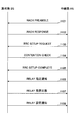
- FIG. 11 is a sequence diagram showing a registration process between the base station BS and the relay station RS when the relay station RS starts up.
- the relay station RS autonomously transmits a RACH preamble (RACH preamble) to the base station Bs (step 1101).
- RACH preamble a RACH preamble
- the base station BS When the base station BS senses the RACH preamble, it returns a RACH response corresponding to the traffic if there is a margin (step 1102).
- the relay station RS When the relay station RS transmits the RACH preamble, it waits for a RACH response. When a RACH response is received within a predetermined time, it is recognized that transmission is permitted, and an RRC setup request (RRC setup Request) is transmitted with the network ID equivalent of the mobile station UE (step 1103).
- RRC setup Request RRC setup Request
- the base station BS When receiving the RRC setup request, the base station BS returns a contention check including the network ID equivalent of the mobile station UE (Step 1104). Since this contention check notifies the ID of a single mobile station UE, it is possible to select only one UE even if other mobile stations UE are crossed during the RACH procedure (RACH procedure). Therefore, it is called Contention Check (competition check).
- the relay station RS transmits an RRC setup request complete (RRC setup request Complete) to the base station BS in response to the RRC setup request (RRC setup request) in the RACH procedure (RACH procedure) (step 1105).
- the relay station RS transmits a relay designation notification indicating that the local station is a relay station (step 1106).
- the base station BS Upon receiving this notification, the base station BS returns a relay designation response indicating that the communication partner is recognized as the relay station RS (step 1107).
- the base station BS transmits setting information required by the relay station RS (MCS between the base station and the relay station, transmission power of the relay station, carrier frequency after relay, etc.) as a relay setting notification (Ste 1108).
- the relay station RS functions as a relay station upon receiving this setting.
- FIG. 12 is a block diagram showing the configuration of the base station BS related to signaling.
- the signal received by the antenna 1201 is sent to the PHY 1203 via the duplexer 1202.
- the PHY 1203 extracts the MAC_SDU from the received signal and sends it to the upper layer receiving unit 1204.
- the upper layer receiving unit 1204 extracts the control command of the radio unit from the received MAC_SDU.
- the base station BS implements the following processing circuit in order to recognize the relay station RS and start up correctly based on the extracted control command.
- the Relay designation receiving unit 1205 receives the Relay designation notification message that the relay station RS notifies after the RACH process, from the control command extracted by the upper layer receiving unit 1204.
- the relay initial setting unit 1206 is necessary in the relay station RS in consideration of the radio state with the relay station RS and the installation status of the surrounding base stations and relay stations in accordance with the relay designation notification message received by the relay designation receiving unit 1205. Determine the setting to be
- the relay response transmission unit 1207 returns a response (Relay designation response) indicating that the relay designation notification has been received from the relay station RS to the relay station RS.
- the relay station initial setting value (relay setting notification) determined by the relay initial setting unit 1206 is sent to the upper layer transmission unit 1208.
- the higher layer transmission unit 1208 uses the response from the Relay response transmission unit 1207 and the Relay station initial setting value as MAC_SDU, generates a MAC_PDU according to the wireless state, and sends it to the PHY 1209.
- the MAC_PDU is converted into a signal format by the PHY 1209 and transmitted from the antenna 1201 via the duplexer (DUP) 1202.
- DUP duplexer
- FIG. 13 is a block diagram illustrating a configuration of a relay station related to signaling.
- the Relay designation transmitting unit 1301 transmits information indicating that the local station is not a normal UE but a relay station.
- the upper layer transmission unit 1302 uses the information as MAC_SDU and generates MAC_PDU according to the radio state.
- the PHY 1303 converts the MAC_PDU generated by the higher layer transmission unit 1302 into a signal format and transmits the signal from the antenna 1305 via the duplexer (DUP) 1304.
- DUP duplexer
- a signal received by the antenna 1305 is sent to the PHY 1306 via a duplexer (DUP) 1304.
- DUP duplexer
- the PHY 1306 extracts the MAC SDU from the received signal and sends it to the upper layer receiving unit 1307.
- the upper layer receiving unit 1307 extracts the control command of the radio unit from the MAC_SDU.
- the relay station implements the following processing circuit in order to recognize the base station BS based on the extracted control command and start up correctly.
- the Relay response receiving unit 1308 receives a response (Relay designation response) of the base station BS that the Relay designation notification from the relay station RS has been received.
- PHY_ID As a relay station is assigned, and PHY_ID as a relay station is applied instead of PHY_ID as a communication terminal.
- the relay station setting reception unit 1309 receives the relay station initial setting value that follows the relay designation response, and sets the setting value in its own device. Thereby, relay station RS starts the operation
- FIG. 14 is a flowchart showing operations of the base station BS, the relay station RS, and the mobile station UE during downlink.
- the base station BS extracts transmission data from the L2 buffer provided for each UE (step 1401), and generates a MAC_PDU in which transmission data for each UE is multiplexed (step 1402).
- a PHY is generated from this MAC_PDU (step 1403) and transmitted as a transmission signal (step 1404).
- the relay station RS receives the transmission signal transmitted by the base station BS (step 1405), and demodulates and decodes (step 1406).
- MAC_SDU is separated for each mobile station UE from the demodulated / decoded received data (step 1407), PHY is generated (step 1408), and transmitted as a transmission signal (step 1409).
- Each mobile station UE receives a transmission signal addressed to itself from the relay station RS (step 1410), and demodulates and decodes the PHY (step 1411).
- MAC_SDU is extracted from the demodulated / decoded received data (step 1412), and the received data is stored in the L2 buffer of the own station (step 1413).
- FIG. 15 is a flowchart showing operations of the mobile station UE, the relay station RS, and the base station BS during uplink.
- Each mobile station UE1 to UEn extracts transmission data from its own L2 buffer (step 1501), and generates a MAC_PDU (step 1502).
- a PHY is generated from this MAC_PDU (step 1503) and transmitted as a transmission signal (step 1504).
- the relay station RS receives the transmission signals transmitted by the mobile stations UE1 to UEn (step 1505), demodulates and decodes the PHY, and obtains MAC_SDU (step 1506).
- the obtained MAC_SDU is multiplexed to generate a MAC_PDU (step 1507).
- a PHY is generated from the generated MAC_PDU (step 1508) and transmitted as a transmission signal (step 1509).
- the base station BS receives the transmission signal of the relay station RS (step 1510), and demodulates and decodes the PHY (step 1511). Then, the MAC_SDU for each mobile station UE is extracted from the demodulated / decoded PHY, and the received data is stored in the L2 buffer provided in each mobile station UE (step 1513).
- FIG. Will be described in detail with reference to FIG.
- FIG. 16 is a flowchart showing separation of mobile stations UE and replacement of IDs in the MAC layer during downlink.
- the relay station RS demodulates and decodes the PHY received from the base station BS (step 1601), and analyzes the MAC header included in the received data (step 1602). Then, the number of UE_IDs of the mobile station UE multiplexed on the received data is counted (step 1603), and the number of multiplexed mobile stations UE is recognized (step 1604).
- the relay station RS extracts MAC_PDU for each multiplexed mobile station UE (step 1605A).
- UE_ID is extracted (step 1605B), and UE_ID is converted into PHY_ID (step 1605C).
- steps 1601A to 1605C are performed for each mobile station UE (step 1605).
- the relay station RS generates a PHY for each multiplexed mobile station UE based on the extracted MAC_PDU and the converted PHY_ID (step 1606).
- FIG. Will be described in detail with reference to FIG.
- FIG. 17 is a flowchart showing multiplexing of mobile stations UE and replacement of IDs in the MAC layer during uplink.
- the relay station RS demodulates and decodes the PHY received from each mobile station UE (step 1701A).
- MAC_SDU is extracted from the demodulated / decoded received data (step 1701B), and in parallel therewith, PHY_ID is extracted (step 1701C) and PHY_ID is converted to UE_ID (step 1701D).
- steps 1701A to 1701D are performed for each mobile station UE (step 1701).
- the relay station RS generates a MAC_PDU based on the extracted MAC_SDU and the converted UE_ID (step 1702), and generates a PHY from the MAC_PDU (step 1703).
- the base station BS, the relay station RS, and the mobile station UE described with reference to FIGS. 6 to 8 have a configuration in which the scheduler function is integrated in the base station. A part of the scheduler function can be distributed to the relay stations RS. Hereinafter, the configuration of the scheduler will be described.
- FIG. 18 is a block diagram showing a configuration of a base station intensive scheduler 1800.
- the scheduler 1800 includes a scheduler unit 1801 that performs resource allocation according to the propagation path between the base station (eNB) and the relay station (Relay) as a master.
- the scheduler part 1802 which performs the resource allocation according to a propagation path with respect to the relay station (Relay) and each mobile station UE by making the resource allocated by the scheduler part 1801 into an upper limit.
- scheduler control signal unit 1803 for multiplexing and notifying a control signal from the scheduler unit 1801 of the base station and the relay station and a control signal from the scheduler unit 1802 of the relay station and the mobile station UE.
- FIG. 19 is a diagram for explaining a constraint condition of throughput when the base station intensive scheduler configuration shown in FIG. 18 is adopted.
- FIG. 20 is a diagram showing a protocol configuration when a base station intensive scheduler is used.
- the scheduler multiplexes and notifies in a two-layer configuration in consideration thereof.
- a relay station distributed scheduler that distributes a part of the scheduler function to relay stations for the above base station intensive scheduler will be described.
- FIG. 21 is a diagram showing a protocol configuration when a relay station distributed scheduler is used.
- the MAC Since the base station and the relay station each have a scheduling function, the MAC is completely terminated at the relay station as shown in FIG. In order to perform completely independent scheduling, the relay station needs a buffer.
- FIG. 22 is a block diagram showing a configuration example of the relay station RS when the relay station distributed scheduler is used.
- the relay station RS shown in FIG. 22 has L2 buffers (L2 Buffers) 2201 and 2202 for each of the mobile stations UE1 to UEn, between the base station BS and the relay station RS, and between the relay station RS and each mobile station. It is possible to operate with completely independent scheduling between the stations UE1 to UEn.
- L2 Buffers L2 Buffers
- the base station side has DL / UL scheduler control signal extraction sections 2203 and 2204, and uses the scheduler control signal from the base station.
- the mobile station side has DL / UL scheduler control signal generation units 2205 and 2206, and operates by scheduling independent of the base station side.
- the relay station RS can allocate resources in consideration of the buffer amount of the L2 buffer (L2 Buffer) and QoS.
- the present invention is applicable to a relay station, a base station, a relay method, and a communication method in a wireless communication network.
Abstract
一実施形態による中継局は、複数の移動局からの信号から移動局の物理レイヤの識別情報を抽出する抽出部と、前記物理レイヤの識別情報をデータリンクレイヤであるMACレイヤの識別情報に変換し、前記複数の移動局のMACレイヤの識別情報をヘッダに含み、前記複数の移動局からの信号のサービスデータユニットを含むプロトコルデータユニットを構成する多重部とを有する。
Description
本発明は、無線通信ネットワークにおける中継局、基地局、中継方法、及び通信方法に関する。
移動体通信システムでは、建物遮蔽による電波伝搬減衰が激しい場所や基地局から離れた場所などの電波の不感地帯が生じる問題がある。この問題を解決するため、IEEE802.16j、IEEE802.16m、LTE-Advanced等において、リレー中継局の標準化が議論されている。
リレー中継局として様々な種類が検討されている。大別すると、振幅増幅器を加えて遅延を抑えつつ中継するアンプリチュード・アンド・フォワード(AF(Amplitude and Forward))方式と、データを復号して誤り訂正確認を行ってから中継するデコード・アンド・フォワード(DF(Decode and Forward))方式の2種類がある。
また、DF方式の一タイプとして、データリンクレイヤであるMACレイヤにおいてMACサービスデータユニット(SDU(Service Data Unit))を復元し、中継時にトランスポートブロック(TB(Transport Block))のサイズに合わせて新たにMACプロトコルデータユニット(PDU(Protocol Data Unit))を形成し、それに合わせて送信方式・符号化・変調を変更するMAC中継タイプがある。
このMAC中継タイプでは、MAC_SDUからMAC_PDUに再マッピングする際に、移動局UEの多重や各移動局UEへの分離も考慮して、移動局UEのIDをMACレイヤにおいて付与し、UE管理の明確化を図っている。
MAC中継タイプの中継局は、このようにMAC中継時に複数のUEのMAC_SDUを結合して一つのMAC_PDUにまとめること、及び基地局と中継局で段階的なスケジューリング機能を持たせることができ、符号長が長くなることにより符号化利得が得られるという特長がある。
図1は、従来のMAC中継タイプの通信システム100を示す概略図である。通信システム100は、移動局UE1、UE2と、中継局RSと、基地局BSとを含む。
MACレイヤにおいて、移動局UE1が中継局RSに送信するMAC_PDU11は、UE1の識別情報(UE_ID)を含むMACヘッダ111とUEデータ112とを含む。また、移動局UE2が中継局RSに送信するMAC_PDU12は、移動局UE2の識別情報(UE_ID)を含むMACヘッダ121とUEデータ122とを含む。
中継局RSは、これらを多重してMAC_PDU13を構成する。MAC_PDU13には、中継局RSの識別情報(Relay_ID)を含むMACヘッダ131と、UE1のMACヘッダ111及びUEデータ112と、UE2のMACヘッダ121及びUEデータ122とを含む。
MAC_PDU11、12、13は、いずれも同じスクランブルコード(スクランブルA)で送信される。
このように、従来の通信システム100において中継局RSは、一つのトランスポートブロックTBに各移動局UEの識別情報を含め、その識別情報をデータの単位の目印として用いている。各UEのデータは識別情報により識別される。
特開2008-99283号公報
特開2008-104096号公報
従来の通信システムでは、MACヘッダに移動局の情報を付加することにより、制御の自由度が向上する。しかし、移動局UEのID情報111、121とともに中継局RSのID情報131を制御情報に含める。このため、制御情報の増加により通信効率が低下するという問題があった。
一実施形態による中継局は、複数の移動局からの信号をデスクランブルして、移動局の物理レイヤの識別情報を抽出する抽出部と、前記物理レイヤの識別情報をデータリンクレイヤであるMACレイヤの識別情報に変換し、前記複数の移動局のMACレイヤの識別情報をヘッダに含み、前記複数の移動局からの信号のサービスデータユニットを含むプロトコルデータユニットを構成する多重部とを有する。
他の実施形態による中継局は、複数の移動局のデータリンクレイヤであるMACレイヤの識別情報をヘッダに含み、前記複数の移動局からの信号のサービスデータユニットを含む基地局からの信号に含まれるMACレイヤの識別情報を物理レイヤの識別情報に変換し、各移動局に対応するサービスデータユニットを分離する分離部とを有する。
一実施形態による、複数の移動局からの信号を基地局に中継する中継方法は、前記信号から移動局の物理レイヤの識別情報を抽出する段階と、前記物理レイヤの識別情報をデータリンクレイヤであるMACレイヤの識別情報に変換する段階と、前記複数の移動局のMACレイヤの識別情報をヘッダに含み、前記複数の移動局からの信号のサービスデータユニットを含むプロトコルデータユニットを構成する段階とを含む。
さらに他の実施形態による、基地局からの信号を複数の移動局に中継する中継方法は、前記信号は、複数の移動局のデータリンクレイヤであるMACレイヤの識別情報をヘッダに含み、前記複数の移動局からの信号のサービスデータユニットを含み、前記信号に含まれるMACレイヤの識別情報を物理レイヤの識別情報に変換する段階と、各移動局に、対応するサービスデータユニットに前記物理レイヤの識別情報を付した信号を送信する段階とを含む。
制御情報を減少させ通信効率を向上することができる。
BS 基地局
RS 中継局
UE、UE1~n 移動局
601、616 L2バッファ
602 DLスケジューラ制御信号発生部
603 MAC_PDU生成部
604 符号化部
605 リレーPHY_IDスクランブル部
606 変調部
607 多重部
608 RS送信部
609 デュプレクサ(DUP)
610 アンテナ
611 RF受信部
612 復調部
613 リレーPHY_IDデスクランブル部
614 復号部
615 MAC_SDU抽出部
701、717 アンテナ
702、716 デュプレクサ(DUP)
703、718 RF受信部
704、719 分離部
705 DLスケジューラ制御信号抽出部
706 ULスケジューラ制御信号抽出部
707、720 復調部
708 中継局PHY_IDデスクランブル部
709、722 復号部
710 MAC_SDU分離部
711、724 符号化部
712 移動局PHY_IDスクランブル部
713、726 変調部
714 多重部
715、727 RF送信部
721 移動局PHY_IDデスクランブル部
723 MAC_PDU多重部
725 中継局PHY_IDスクランブル部
801 アンテナ
802 デュプレクサ(DUP)
803 RF受信部
804 分離部
805 DLスケジューラ制御信号抽出部
806 ULスケジューラ制御信号抽出部
807 復調部
808 移動局PHY_IDデスクランブル部
809 復号部
810 MAC_SDU抽出部
811 MAC_PDU生成部
812 符号化部
813 移動局PHY_IDスクランブル部
814 変調部
815 RF送信部
901 MACヘッダ解析部
902 UE_ID抽出部
903 ID変換部
904 変換テーブル
1001 ID変換部
1002 変換テーブル
1003 MAC_PDU生成部
本発明の実施形態を詳細に説明する。以下の実施形態は、例えば、LTE(Long Term Evolution)、LTE-Advanced等に適用可能である。
図2は、一実施形態による通信システム200を示す概略図である。通信システム200は、移動局UE1、UE2と、中継局RSと、基地局BSとを含む。
移動局UE1は、送信データにCRC(Cyclic Redundancy Check)を加え、符号化した後に移動局UE1のスクランブル(Scramble)1を行って変調して、MAC_PDU21としてアンテナから送信する。
また、移動局UE2は、送信データにCRC(Cyclic Redundancy Check)を加え、符号化した後に移動局UE2のスクランブル(Scramble)2(移動局UE1のスクランブル1とは異なる)を行って変調して、MAC_PDU22としてアンテナから送信する。
以下、UE毎のスクランブル系列をPHY_IDと呼ぶ。
このように、UE_IDを、それに相当する特有のスクランブル系列(PHY_ID)に置き換えて通信することにより、MACヘッダの付与量を低減することができる。
一方、基地局BSからは、中継局RSも1つの移動局UEとして見える。中継局RSは、一つのトランスポートブロックTBに複数の移動局UE1、UE2のMAC_SDUを含めてMAC_SDUとする。そのMAC_SDUに、CRCを加え、符号化した後に中継局RSを示すスクランブルS(PHY_ID)を行って変調して、MAC_PDU23としてアンテナより送信する。
移動局ごと、または中継局ごとのスクランブルをかけるタイミングは、符号化前でも符号化後でもよい。
また、このような構成にすると、移動局UEと中継局RSとの間で用いていたPHY_IDの情報が欠落してしまうため、MAC_PDUの中にマッピングされた全ての移動局UEのヘッダ情報を集めて、中継局ヘッダ231を生成しMACヘッダとして付与する。
このように、各移動局UE1、UE2と中継局RSとの間でMACヘッダの付与量を減らし、情報通信利用効率を向上することができる。
図3乃至図5を参照して中継局における処理を説明する。
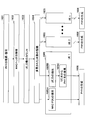
図3は、一実施形態による中継局RSにおける処理を示す概略図である。
図3に示したように、PHYレイヤにおいて、各移動局UE1、UE2がそれぞれ送信する送信データ311、312には、移動局特有のスクランブルコードによるスクランブル化がされている。
中継局RSは、UE特有のスクランブル系列をデスクランブルし、CRCチェックが成功すればそのスクランブル系列は正しいものと判定する。これにより各UEのPHY_IDを抽出できる(ステップA1、A2)。
デスクランブル用に適用するスクランブル系列については、予め中継局RSでスケジューラ情報をトレーニングして特定しておくことが可能である。
CRCチェックが成功しPHY_IDを抽出すると、各移動局UE1、UE2についてMACレイヤにてそれぞれMAC_PDU321、322とPHY_ID331、332が得られる。
図4は、図3に続く、一実施形態による中継局RSにおける処理を示す概略図である。
図3を参照して説明したように、各移動局UE1、UE2のMACレイヤにおけるMAC_PDU321、322とPHY_ID331、332が得られている。
移動局UEごとに、PHYレイヤにおけるPHY_IDからMACレイヤにおけるUE_IDへの変換を行う(ステップB)。
この変換は、例えば、PHY_IDとUE_IDを対応させて記憶しているテーブルから、PHY_IDに対応するUE_IDを検索することにより行う。PHY_IDにより特定されるUEの識別情報が失われないように、検索したUE_IDをMACヘッダに埋め込む。
なお、上記の変換は、物理レイヤにマッピングするために好適な形態にPHY_IDが変換されている場合に必要となる。しかし、PHY_IDとUE_IDが同一である場合は変換処理を行う必要はない。
次に、各UEのMAC_PDUを多重して、新たなMAC_PDUを生成する(ステップC)。これにより、各UEのMAC_PDUの先頭にUE_ID情報411、412を挿入した信号フォーマット41が得られる。
図4に示したフォーマット41では、UEごとにまとまってMAC_PDUが配置されているため、MACヘッダとMAC_SDUとが混在している。これをLTE、LTE-Advanced等で送信しやすくするため、さらにフォーマット41を図5のフォーマット50のように変更してもよい。
図5は、UE多重後のMAC_PDUのフォーマット50を示す図である。
図5に示したフォーマット50では、MACヘッダ情報が全て先頭に集められている。
フォーマット50は、移動局UE1、UE2にそれぞれ対応する、MACレイヤにて挿入されているPHYレイヤの制御情報であるMACコントロールエレメント(MAC-CE(Control Element))511、512を含む。MACコントロールエレメントは、MACレイヤに挿入されている物理レイヤの制御情報を示す。
移動局UE1、UE2にそれぞれ対応するMAC_SDUのフォーマット指令521、522は、MAC_SDUのLCH(Logical CHannel)や情報長等を通知する。
移動局UE1、UE2にそれぞれ対応するC-RNTI531、532は、基地局で管理しているUE_IDであり、MACレイヤ~RRCレイヤにおいてIDとして使われる。C-RNTIは基地局が自セルに在圏するユーザ装置各々に一意に割り当てる識別子である。
フォーマット50は、さらに、MAC_SDUメッセージ541、542を含む。
このようにして、移動局UEと中継局RSとの間で、UE-IDをPHYレイヤにマッピングすることにより、MACヘッダの冗長性を減らして無線帯域利用効率を向上することができる。さらに、中継局RSは、MAC_PDU生成時に複数UEを結合して一つのトランスポートブロックTBに含める情報を多くして符号化利得を向上させ、実行スループットを向上させることができる。
次に、図2乃至図5を参照して説明したUE多重化を実現する基地局、中継局、移動局のそれぞれの構成を説明する。
図6は、基地局BSの構成例を示すブロック図である。
ダウンリンク(DL)側の信号伝送時の動作を説明する。
コアネットワーク(図示せず)より基地局BSに到来した情報パケットは、秘匿・IPヘッダ圧縮などの上位レイヤにおける処理を受けた後に、送信先のUEに対応したL2バッファ601に格納される。
DLスケジューラ制御信号発生部602は、適切なアルゴリズムに従ってそれぞれのUEに送信機会を与える制御信号を発生する。
図6では、基地局BSから中継局RSを経由してUEに送信される情報パケットの流れを示している。そのため、DLスケジューラ制御信号発生部602は、中継局RSに割り当てる情報パケット情報量と、その情報量から分配する中継局RS経由の各UEの情報パケット量を考慮して、MAC_PDU生成を指令する。
MAC_PDU生成部603は、DLスケジューラ制御信号発生部602の制御信号に応じて、送信される情報量(トランスポートブロックTB)ずつL2バッファ601から情報パケットを読み出し、所定フォーマットに従ってMAC_PDUを生成する。
MAC_PDU生成部603は、UE_ID情報を含むMACヘッダ情報を加えて、複数のUEを多重して一つのMAC_PDUを生成し、符号化部604に送る。
符号化部604は、基地局BSと中継局RSの伝搬路に応じた誤り訂正符号化を行い、スクランブル部605に送る。
スクランブル部605は、中継局RS向けを示すスクランブル化を行い、変調部606に送る。
変調部606は、適切な変調を行い、多重部607に送る。
多重部607は、DLスケジューラ制御信号発生部602の制御信号とアップリンク(UL)スケジューラ制御信号発生部617の制御信号とを多重して、RF送信部608に送る。
RF送信部608は、RF(Radio frequency)帯にアップコンバートし、デュプレクサ(DUP)609を介してアンテナ610から送信する。
次に、UL側の信号伝送時の動作を説明する。
アンテナ610で受信された信号はデュプレクサ609を介してRF受信部611に送られる。RF受信部611は、受信信号をベースバンド(Base Band)帯にダウンコンバートして、復調部612に送る。
復調部612は、過去に指令したULスケジュール情報を基に適切な復調を行い、デスクランブル部613に送る。
デスクランブル部613は、中継局RSから基地局BSへの転送を確認するデスクランブル化を行い、復号部614に送る。
復号部614は、誤り訂正復号化を行い、MAC_SDU抽出部615に送る。
CRCチェックが成功した場合、MAC_SDU抽出部615は、正しく受信できたMAC_PDUからMAC_SDUの切り出し処理を行う。そして、MACヘッダに含まれたUE_ID情報に基づき、UEごとにL2バッファ616の正しい場所に情報を格納する。
L2バッファ616は、情報パケットが複製できると上位レイヤへ転送する。
L2バッファ616から出力された情報は、秘匿解除・IPヘッダ伸張などの処理を受けた後に、コアネットワーク(図示せず)へ出力される。
なお、図6に示した基地局BSでは、UEごとにL2バッファを設けたが、他の実施形態では、単一のL2バッファを複数のUEのために使用してもよい。
図7は、中継局RSの構成例を示すブロック図である。
DL側の信号伝送時の動作を説明する。
アンテナ701で受信された信号はデュプレクサ(DUP)702を介してRF受信部703に送られる。
RF受信部703は、受信信号をベースバンド帯にダウンコンバートし、分離部704に送る。
分離部704は、DLスケジューラ情報とULスケジューラ情報を読み出してDLスケジューラ制御信号抽出部705とULスケジューラ制御信号抽出部706に送る。
復調部707は、読み出されたDLスケジューラ情報に基づいて、受信信号に中継局向けの復調を行い、RS_PHY_IDデスクランブル部708に送る。
RS_PHY_IDデスクランブル部708は、基地局BSから中継局RSへの転送を確認するデスクランブル化を行い、復号部709に送る。
復号部709は、誤り訂正復号化を行い、MAC_SDU分離部710に送る。復号部709で、CRCチェックをパスすれば、MAC_PDUが正しく受信できたことになる。
MAC_SDU分離部710は、MACヘッダ情報を参照して、MAC_PDUからMAC_SDUを分離し、中継局RS向けや各UE向けの信号を区分ける処理を行う。ここで、中継局RS向けの信号があれば、上位レイヤへ転送する。
符号化部711は、UEごとに分離された受信信号を、UE単位で中継局とUE間の伝搬路に応じた誤り訂正符号化を行い、UE_PHY_IDスクランブル部712に送る。
UE_PHY_IDスクランブル部712は、UE向けを示すスクランブル化を行い、変調部713に送る。
変調部713は、適切な変調を行って、多重部714に送る。
多重部714は、DLスケジューラ制御信号抽出部705の制御信号とULスケジューラ制御信号抽出部706の制御信号とを多重して、RF送信部715に送る。
RF送信部715は、RF帯にアップコンバートして、デュプレクサ(DUP)716を介して、アンテナ717から送信する。
次に、UL側の信号伝送時の動作を説明する。
アンテナ717で受信された信号は、デュプレクサ(DUP)716を介して、RF受信部718に送られる。
RF受信部718は、受信信号をベースバンド帯にダウンコンバートして、分離部719に送る。
分離部719は、過去に指令されたULスケジュール情報に基づき、UE毎に分離して、復調部720に送る。
復調部720は、それぞれのUEに対して適切な復調を行い、UE_PHY_IDデスクランブル部721に送る。
UE_PHY_IDデスクランブル部721は、UEから中継局への転送を確認するデスクランブル化を行い、復号部722に送る。
復号部722は、誤り訂正復号化を行い、MAC_PDU多重部723に送る。CRCチェックをパスすると、正しくMAC_PDUが受信できた事となる。
MAC_PDU多重部723は、CRCチェックをパスした全てのUEを、一つのMAC_PDUとするUE多重を行い、符号化部724に送る。なお、中継局RSの上位レイヤから基地局BSに送るべき信号がある場合、MAC_PDU多重部723は、これも多重する。多重は、UE_PHY_IDに相当する情報をMACヘッダに含め、UEを識別できるようにして行う。
このように、MAC_PDU多重部723がMAC_PDUを再構築した後、符号化部724は、中継局RSから基地局BSへの伝搬路に応じた誤り訂正符号化を行い、RS_PHY_IDスクランブル部725に送る。
RS_PHY_IDスクランブル部は、中継局RSから基地局BSへの情報であることを示すスクランブル化を行い、変調部726に送る。
変調部726は、適切な変調を行い、RF送信部727に送る。
RF送信部727は、送信信号をRF帯へアップコンバートし、デュプレクサ702を介してアンテナ701から送信する。
図8は、移動局UEの構成例を示すブロック図である。
DL側の信号伝送時の動作を説明する。
アンテナ801で受信された信号は、デュプレクサ802を介してRF受信部803に送られる。
RF受信部803は、受信信号をベースバンド帯にダウンコンバートして、分離部804に送る。
分離部804は、DLスケジューラ情報とULスケジューラ情報を読み出し、復調部807に送る。また、DLスケジューラ情報とULスケジューラ情報はそれぞれDLスケジューラ制御信号抽出部805とULスケジューラ制御信号抽出部806に送られる。
復調部807は、読みだしたDLスケジューラ情報を基にして、自機向けの復調を行い、UE_PHY_IDデスクランブル部808に送る。
UE_PHY_IDデスクランブル部808は、中継局RSからUEへの転送を確認するデスクランブル化を行い、復号部809に送る。
復号部809は、誤り訂正復号化を行い、MAC_SDU抽出部810に送る。CRCチェックをパスするとMAC_PDUが正しく受信できたことを意味する。
MAC_SDU抽出部810は、MACヘッダ情報を用いて、MAC_PDUからMAC_SDUを抽出し、上位レイヤへ転送する。
UL側の信号伝送時の動作を説明する。
上位レイヤより発生した情報パケットは、秘匿やIPヘッダ圧縮などの処理を行ってMAC_SDU化される。
MAC_PDU生成部811は、ULスケジューラで指令された送信できる情報量の分だけMAC_SDUを束ねてMAC_PDUを生成して、符号化部812に送る。
符号化部812は、移動局UEから中継局RSへの伝搬路に応じた誤り訂正符号化を行い、UE_PHY_IDスクランブル部813に送る。
UE_PHY_IDスクランブル部813は、UEから中継局向けを示すスクランブル化を行い、変調部814に送る。
変調部814は、適切な変調を行い、RF送信部815に送る。
RF送信部815は、RFへアップコンバートして、デュプレクサ(DUP)802を介してアンテナから送信する。
以上、基地局BS、中継局RS、移動局UEにおける信号伝送時の動作を説明した。ここで、中継局RSにおけるダウンリンク側のUE分離とアップリンク側のUE多重について、さらに詳しく説明する。
[UE分離]
図9は、図7に示した中継局RSのMAC_SDU分離部710の構成例を示すブロック図である。
[UE分離]
図9は、図7に示した中継局RSのMAC_SDU分離部710の構成例を示すブロック図である。
CRCチェックをパスしたMAC_PDUは、MACヘッダ解析部901に入力される。
MACヘッダ解析部901は、入力されたMAC_PDUのMACヘッダを解析し、UE_ID抽出部902に送る。
UE_ID抽出部902は、UEごとに、MACヘッダに含まれるUE_IDと、そのUE_IDに対応するMAC_PDUとを抜き出す。UE_IDは、UEごとにID変換部903に送られる。また、MAC_PDUは、UEごとに符号化部711(図7)に送られる。
ID変換部903は、変換テーブル904を参照して、UE_IDをスクランブルとして用いるPHY_IDに変換する。そして、このPHY_IDは、UEごとに符号化部711(図7)に送られる。
このように、MAC_SDU分離部710は、図2ないし5を参照して説明したUE多重とは逆のUE分離を行うことができる。
[UE多重]
図10は、図7に示した中継局RSのMAC_SDU多重部723の構成例を示すブロック図である。
[UE多重]
図10は、図7に示した中継局RSのMAC_SDU多重部723の構成例を示すブロック図である。
MAC_SDU多重部723には、CRCチェックをパスしたユーザ毎のMAC_PDUと、それに対応するPHY_IDが入力される。
PHY_IDは、ID変換部1001により、変換テーブル1002を用いて、MACレイヤにて認証できるUE_IDに変換される。変換されたUE_IDとMAC_PDUは、ユーザ毎にMAC_PDU生成部1003へ入力される。
PDU生成部1003は、図5を参照して説明した、UE_IDをMACヘッダに含めるフォーマットを利用して、対応するUE全てを一つのMAC_PDUに多重し、符号化部724に送る。
このように、MAC_SDU多重部723は、図2ないし5を参照して説明したUE多重を行うことができる。
[中継局認識]
次に、中継局RSの認識について説明する。
[中継局認識]
次に、中継局RSの認識について説明する。
上記の実施形態による中継局RSは、基地局BSから見ると特別な移動局UEであると認識される。
そこで、中継局RSを新たに設置して立ち上げる時、または中継局RSが省エネモード(RRC idle)からアクティブ(RRC connected)に立ち上がる時に、基地局BSが中継局RSを認識して通信を始めるまでの準備が必要である。
中継局RSは、立ち上がる時、基地局BSに対して普通の移動局UEと同様にRACH処理でRRC接続要求を行い、次いで中継局の通信設定を行う。
図11は、中継局RSの立ち上がり時における、基地局BSと中継局RSとの間の登録処理を示すシーケンス図である。
中継局RSは、基地局Bsに対して自律的にRACHプリアンブル(RACH preamble)を送信する(ステップ1101)。
基地局BSは、RACHプリアンブル(RACH preamble)を感知すると、トラヒックに余裕があればそれに応じたRACHレスポンス(RACH Response)を返す(ステップ1102)。
中継局RSは、RACHプリアンブルを送信すると、それに対するRACHレスポンスを待つ。そして、予め決められた時間内にRACHレスポンスを受信すると、送信が許可されたと認識して移動局UEのネットワークID相当を乗せてRRCセットアップリクエスト(RRC setup Request)を送信する(ステップ1103)。
基地局BSは、RRCセットアップリクエストを受信すると、移動局UEのネットワークID相当を含めたコンテンション・チェック(Contention Check)を返す(ステップ1104)。このコンテンション・チェックは、単一の移動局UEのIDを通知しているために、RACHプロシージャ(RACH procedure)中に他の移動局UEと混線していても唯一のUEを選択できる。そのため、Contention Check(競合確認)と呼ばれる。
ここまではRACHプロシージャ(RACH procedure)である。
中継局RSは、RACHプロシージャ(RACH procedure)内のRRCセットアップリクエスト(RRC setup Request)に対するRRCセットアップリクエストコンプリート(RRC setup Request Complete)を基地局BSに送信する(ステップ1105)。
中継局RSは、その後、自局が中継局である事を示唆するリレー(Relay)指定通知を送信する(ステップ1106)。
基地局BSは、この通知を受け取ると、通信相手が中継局RSであると認識したことを示すリレー(Relay)指定応答を返す(ステップ1107)。
また、基地局BSは、中継局RSが必要とする設定情報(基地局と中継局間のMCS、中継局の送信電力、中継後の搬送波周波数など)をリレー(Relay)設定通知として送信する(ステップ1108)。
中継局RSは、この設定を受けた時点で、中継局として機能するようになる。
図11を参照して説明した登録処理のシーケンスを実現する、基地局BSの動作を説明する。図12は、シグナリングに関する基地局BSの構成を示すブロック図である。
アンテナ1201で受信された信号は、デュプレクサ1202を経由してPHY1203に送られる。
PHY1203は、受信信号からMAC_SDUを抽出し、上位レイヤ受信部1204に送る。
上位レイヤ受信部1204は、受け取ったMAC_SDUから無線部の制御命令を抽出する。
基地局BSは、抽出された制御命令に基づき、中継局RSを認識して正しく立ち上げるために次の処理回路を実装する。
Relay指定受信部1205は、上位レイヤ受信部1204が抽出した制御命令から、中継局RSがRACHプロセス後に通知するRelay指定通知メッセージを受信する。
Relay初期設定部1206は、Relay指定受信部1205が受信したRelay指定通知メッセージに応じて、中継局RSとの無線状態や周囲の基地局や中継局の設置状況を考慮して中継局RSにおいて必要となる設定を決定する。
Relay応答送信部1207は、中継局RSからのRelay指定通知を受け取った旨の応答(Relay指定応答)を中継局RSに返す。次に、Relay初期設定部1206が決定したRelay局初期設定値(Relay設定通知)を上位レイヤ送信部1208に送る。
上位レイヤ送信部1208は、Relay応答送信部1207からの応答とRelay局初期設定値をMAC_SDUとし、無線状態に合わせてMAC_PDUを生成してPHY1209に送る。
MAC_PDUは、PHY1209により信号フォーマットに変換され、デュプレクサ(DUP)1202を介して、アンテナ1201から送信される。
次に、図11を参照して説明した登録処理のシーケンスを実現する、中継局RSの動作を説明する。図13は、シグナリングに関する中継局の構成を示すブロック図である。
RACHプロセスが終わりRRC設定完了(RRC setup Complete)通知を基地局BSに通知した後、Relay指定送信部1301は、自局が普通のUEでは無く中継局である事を示す情報を送信する。
上位レイヤ送信部1302は、その情報をMAC_SDUとし、無線状態に合わせてMAC_PDUを生成する。
PHY1303は、上位レイヤ送信部1302が生成したMAC_PDUを信号フォーマットに変換し、デュプレクサ(DUP)1304を介してアンテナ1305から送信する。
一方、アンテナ1305で受信された信号は、デュプレクサ(DUP)1304を介してPHY1306に送られる。
PHY1306は、受信信号からMACSDUを抽出し、上位レイヤ受信部1307に送る。
上位レイヤ受信部1307は、MAC_SDUから無線部の制御命令を抽出する。
抽出された制御命令に基づいて基地局BSに認識して貰って正しく立ち上げるために中継局は次の処理回路を実装する。
Relay応答受信部1308は、中継局RSからのRelay指定通知を受け取った旨の基地局BSの応答(Relay指定応答)を受信する。
この時、中継局として固有に使用するPHYレイヤIDが割り当てられ、通信端末としてのPHY_IDの代わりに中継局としてのPHY_IDが適用される。
Relay局設定受信部1309は、そのRelay指定応答の後に続くRelay局初期設定値を受信し、その設定値を自機に設定する。これにより、中継局RSは、中継局としての動作を開始する。
図14は、ダウンリンク時の基地局BS、中継局RS、移動局UEの動作を示すフロー図である。
基地局BSは、各UEに対して設けられたL2バッファから送信データを取り出し(ステップ1401)、各UE向けの送信データが多重化されたMAC_PDUを生成する(ステップ1402)。このMAC_PDUからPHYを生成し(ステップ1403)、送信信号として送信する(ステップ1404)。
中継局RSは、基地局BSが送信した送信信号を受信し(ステップ1405)、復調・復号する(ステップ1406)。復調・復号した受信データから移動局UEごとにMAC_SDUを分離して(ステップ1407)、PHYを生成し(ステップ1408)、送信信号として送信する(ステップ1409)。
各移動局UEは、中継局RSから送信された自局宛の送信信号を受信し(ステップ1410)、PHYを復調・復号する(ステップ1411)。復調・復号した受信データからMAC_SDUを抽出し(ステップ1412)、受信データを自局のL2バッファに格納する(ステップ1413)。
図15は、アップリンク時の移動局UE、中継局RS、基地局BSの動作を示すフロー図である。
各移動局UE1~UEnは、自局のL2バッファから送信データを取り出し(ステップ1501)、MAC_PDUを生成する(ステップ1502)。このMAC_PDUからPHYを生成し(ステップ1503)、送信信号として送信する(ステップ1504)。
中継局RSは、各移動局UE1~UEnが送信した送信信号を受信し(ステップ1505)、PHYを復調・復号してMAC_SDUを得る(ステップ1506)。そして、求めたMAC_SDUを多重してMAC_PDUを生成する(ステップ1507)。生成したMAC_PDUからPHYを生成し(ステップ1508)、送信信号として送信する(ステップ1509)。
基地局BSは、中継局RSの送信信号を受信し(ステップ1510)、PHYを復調・復号する(ステップ1511)。そして、復調・復号したPHYから移動局UEごとのMAC_SDUを抽出し、各移動局UEに設けたL2バッファに受信データを格納する(ステップ1513)。
次に、ダウンリンク時の中継局RSにおける、基地局BSからのPHYの復調・復号(図14のステップ1406)から移動局UEごとのPHYの生成(図14のステップ1408)までを、図16を参照して詳細に説明する。
図16は、ダウンリンク時のMACレイヤにおける移動局UEの分離とIDの付け替えを示すフロー図である。
中継局RSは、基地局BSから受信したPHYを復調・復号し(ステップ1601)、受信データに含まれるMACヘッダを解析する(ステップ1602)。そして、その受信データに多重されている移動局UEのUE_ID数をカウントし(ステップ1603)、多重された移動局UEの数を認識する(ステップ1604)。
次に、中継局RSは、多重された移動局UEごとに、MAC_PDUを抽出する(ステップ1605A)。また、それと並行して、UE_IDを抽出し(ステップ1605B)、UE_IDをPHY_IDに変換する(ステップ1605C)。これらのステップ1601A~1605Cは各移動局UEについて行われる(ステップ1605)。
次に、中継局RSは、多重された移動局UEごとに、抽出したMAC_PDUと変換したPHY_IDに基づき、PHYを生成する(ステップ1606)。
次に、アップリンク時の中継局RSにおける、移動局UEからのPHYの復調・復号(図15のステップ1506)から基地局BSへのPHYの生成(図15のステップ1508)までを、図17を参照して詳細に説明する。
図17は、アップリンク時のMACレイヤにおける移動局UEの多重とIDの付け替えを示すフロー図である。
中継局RSは、各移動局UEから受信したPHYを復調・復号する(ステップ1701A)。復調・復号した受信データからMAC_SDUを抽出し(ステップ1701B)、それと並行してPHY_IDの抽出(ステップ1701C)及びPHY_IDからUE_IDへの変換(ステップ1701D)を行う。これらステップ1701A~1701Dは、移動局UEごとに行われる(ステップ1701)。
次に、中継局RSは、抽出したMAC_SDUと変換したUE_IDに基づきMAC_PDUを生成し(ステップ1702)、そのMAC_PDUからPHYを生成する(ステップ1703)。
図6~8を参照してそれぞれ説明した基地局BS、中継局RS、及び移動局UEでは、基地局にスケジューラ機能を集約した構成となっている。スケジューラ機能の一部を中継局RSに分散することもできる。以下、スケジューラの構成について説明する。
図18は、基地局集約型のスケジューラ1800の構成を示すブロック図である。
スケジューラ1800は、まず、マスターとして、基地局(eNB)と中継局(Relay)間の伝搬路に応じたリソース割り当てを行うスケジューラ部1801を有する。
そして、スケジューラ部1801が割り当てたリソースを上限として、中継局(Relay)とそれぞれの移動局UEに対して、伝搬路に応じたリソース割り当てを行うスケジューラ部1802を有する。
そして、基地局と中継局のスケジューラ部1801からの制御信号と、中継局と移動局UEのスケジューラ部1802からの制御信号とを多重して通知するスケジューラ制御信号部1803を有する。
図19は、図18に示した基地局集約型のスケジューラ構成をとったときのスループットの拘束条件を説明するための図である。
基地局から中継局と移動局UEのスケジューリングを行う場合、中継局はデータをバッファする必要が無い。そこで、例えば基地局と中継局との間で100Mbpsで通信している場合、中継局と各移動局UE1~UE3との間での通信レートの総計を100Mbps以下である必要がある。つまり、中継局と3つの移動局UE1~UE3が通信して、それぞれの通信レートがαMbps、βMbps、γMbpsであるとすると、以下の拘束条件を満たさねばならない。
 図20は、基地局集約型スケジューラを用いた場合のプロトコル構成を示す図である。
この場合、中継局で再スケジューリングができないため、MACが一部終端していない。そのため、スケジューラはそれを考慮して2層構成で多重して通知する。
以上の基地局集約型スケジューラに対し、スケジューラ機能の一部を中継局に分散する中継局分散型スケジューラについて説明する。
図21は、中継局分散型スケジューラを用いた場合のプロトコル構成を示す図である。
基地局と中継局がそれぞれスケジューリング機能を備えるため、図21に示したように、中継局でMACが完全に終端している。完全に独立したスケジューリングを行うために、中継局にはバッファが必要となる。
図22は、中継局分散型スケジューラを用いた場合の中継局RSの構成例を示すブロック図である。
図22に示した中継局RSは、各移動局UE1~UEnに対してL2バッファ(L2 Buffer)2201、2202を有し、基地局BSと中継局RSとの間、及び中継局RSと各移動局UE1~UEnとの間を完全に独立したスケジューリングで動作させることができる。
そのため、基地局側では、DL/ULスケジューラ制御信号抽出部2203、2204を有し、基地局からのスケジューラ制御信号を用いる。
一方、移動局側では、DL/ULスケジューラ制御信号生成部2205、2206を有し、基地局側とは独立したスケジューリングで動作している。
また、スケジューリングの独立性が確保されているために、図19を参照して説明した、基地局集約型スケジューラのような拘束条件は該当しない。中継局RSはL2バッファ(L2 Buffer)のバッファ量やQoSを考慮してリソース割り当てが可能である。
以上、本発明の実施の形態について詳述したが、本発明は特定の実施形態に限定されるものではなく、特許請求の範囲に記載された本発明の要旨の範囲内において、種々の変形及び変更が可能である。
本発明は、無線通信ネットワークにおける中継局、基地局、中継方法、及び通信方法に適用可能である。
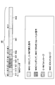
Claims (18)
- 複数の移動局からの信号をデスクランブルして、移動局の物理レイヤの識別情報を抽出する抽出部と、
前記物理レイヤの識別情報をデータリンクレイヤであるMACレイヤの識別情報に変換し、前記複数の移動局のMACレイヤの識別情報をヘッダに含み、前記複数の移動局からの信号のサービスデータユニットを含むプロトコルデータユニットを構成する多重部とを有する中継局。 - 前記抽出部は、移動局の物理レイヤの識別情報を移動局ごとのスクランブル系列に基づき抽出する、請求項1に記載の中継局。
- 前記多重部は、MACレイヤの識別情報を、MACレイヤに挿入されている物理レイヤの制御情報であるMACコントロールエレメントと移動局を識別するための識別子であるC-RNTIを用いて挿入する、請求項2に記載の中継局。
- 構成した前記プロトコルデータユニットを、前記複数の移動局のスクランブル系列とは異なる前記中継局のスクランブル系列でスクランブルを行うスクランブル部をさらに有する、請求項2または3に記載の中継局。
- 基地局とのコネクション確立後、自局が中継局である旨を示す信号を前記基地局に送信し、前記基地局から中継局としてのスクランブル系列を取得する設定部をさらに有する、請求項1ないし4に記載の中継局。
- 請求項1に記載の中継局が中継した複数の移動局からの信号を受信できる基地局であって、
前記信号の物理レイヤの中継局識別情報を認証するデスクランブル部と、
前記物理レイヤから複数の移動局からの信号を抽出する抽出部とを有する基地局。 - 複数の移動局のデータリンクレイヤであるMACレイヤの識別情報をヘッダに含み、前記複数の移動局への信号のサービスデータユニットを含む基地局からの信号に含まれるMACレイヤの識別情報を物理レイヤの識別情報に変換し、各移動局に対応するサービスデータユニットを分離する分離部を有する中継局。
- 移動局の物理レイヤの識別情報に基づき移動局ごとのスクランブル系列を用いてスクランブルをかけるスクランブル部をさらに有する、請求項7に記載の中継局。
- 前記信号は、MACレイヤの識別情報がMACレイヤに挿入されている物理レイヤの制御情報であるMACコントロールエレメントと移動局を識別するための識別子であるC-RNTIを用いて挿入されている、請求項8に記載の中継局。
- 複数の移動局からの信号を基地局に中継する中継方法であって、
前記信号から移動局の物理レイヤの識別情報を抽出する段階と、
前記物理レイヤの識別情報をデータリンクレイヤであるMACレイヤの識別情報に変換する段階と、
前記複数の移動局のMACレイヤの識別情報をヘッダに含み、前記複数の移動局からの信号のサービスデータユニットを含むプロトコルデータユニットを構成する段階とを含む中継方法。 - 移動局の物理レイヤの識別情報を移動局ごとのスクランブル系列に基づき抽出する、請求項10に記載の中継方法。
- MACレイヤの識別情報をMACレイヤに挿入されている物理レイヤの制御情報であるMACコントロールエレメントと移動局を識別するための識別子であるC-RNTIを用いて挿入する、請求項11に記載の中継方法。
- 構成した前記プロトコルデータユニットを、前記複数の移動局のスクランブル系列とは異なるスクランブル系列で前記基地局に送信する段階をさらに含む、請求項11または12に記載の中継方法。
- 基地局とのコネクション確立後、自局が中継局である旨を示す信号を前記基地局に送信する段階と、
前記基地局から中継局としてのスクランブル系列を取得する段階とをさらに含む、請求項10ないし13に記載の中継方法。 - 請求項10に記載の中継方法で中継された複数の移動局からの信号を受信する受信方法であって、
前記信号の物理レイヤの中継局識別情報を認証する段階と、
前記物理レイヤから複数の移動局からの信号を抽出する段階とを含む受信方法。 - 基地局からの信号を複数の移動局に中継する中継方法であって、
前記信号は、複数の移動局のデータリンクレイヤであるMACレイヤの識別情報をヘッダに含み、前記複数の移動局からの信号のサービスデータユニットを含み、
前記信号に含まれるMACレイヤの識別情報を物理レイヤの識別情報に変換する段階と、
各移動局に、対応するサービスデータユニットに前記物理レイヤの識別情報を付した信号を送信する段階とを含む中継方法。 - 移動局の物理レイヤの識別情報は、移動局ごとのスクランブル系列である、請求項16に記載の中継方法。
- 前記信号は、MACレイヤの識別情報がMACレイヤに挿入されている物理レイヤの制御情報であるMACコントロールエレメントと移動局を識別するための識別子であるC-RNTIを用いて挿入されている、請求項17に記載の中継方法。
Priority Applications (4)
| Application Number | Priority Date | Filing Date | Title |
|---|---|---|---|
| PCT/JP2009/056676 WO2010113267A1 (ja) | 2009-03-31 | 2009-03-31 | 無線通信ネットワークにおける中継局、基地局、中継方法、及び通信方法 |
| EP09842622.4A EP2416618A4 (en) | 2009-03-31 | 2009-03-31 | Relay station, base station, method of relaying, and communication method in wireless communication network |
| JP2011506892A JP5304889B2 (ja) | 2009-03-31 | 2009-03-31 | 無線通信ネットワークにおける中継局、基地局、中継方法、及び通信方法 |
| US13/240,491 US20120008547A1 (en) | 2009-03-31 | 2011-09-22 | Relay station, base station, relay method and communication method used in wireless communications network |
Applications Claiming Priority (1)
| Application Number | Priority Date | Filing Date | Title |
|---|---|---|---|
| PCT/JP2009/056676 WO2010113267A1 (ja) | 2009-03-31 | 2009-03-31 | 無線通信ネットワークにおける中継局、基地局、中継方法、及び通信方法 |
Related Child Applications (1)
| Application Number | Title | Priority Date | Filing Date |
|---|---|---|---|
| US13/240,491 Continuation US20120008547A1 (en) | 2009-03-31 | 2011-09-22 | Relay station, base station, relay method and communication method used in wireless communications network |
Publications (1)
| Publication Number | Publication Date |
|---|---|
| WO2010113267A1 true WO2010113267A1 (ja) | 2010-10-07 |
Family
ID=42827600
Family Applications (1)
| Application Number | Title | Priority Date | Filing Date |
|---|---|---|---|
| PCT/JP2009/056676 WO2010113267A1 (ja) | 2009-03-31 | 2009-03-31 | 無線通信ネットワークにおける中継局、基地局、中継方法、及び通信方法 |
Country Status (4)
| Country | Link |
|---|---|
| US (1) | US20120008547A1 (ja) |
| EP (1) | EP2416618A4 (ja) |
| JP (1) | JP5304889B2 (ja) |
| WO (1) | WO2010113267A1 (ja) |
Cited By (6)
| Publication number | Priority date | Publication date | Assignee | Title |
|---|---|---|---|---|
| WO2013051575A1 (ja) * | 2011-10-06 | 2013-04-11 | 株式会社エヌ・ティ・ティ・ドコモ | 基地局及び通信制御方法 |
| WO2013051578A1 (ja) * | 2011-10-06 | 2013-04-11 | 株式会社エヌ・ティ・ティ・ドコモ | 基地局及び通信制御方法 |
| JP2013176167A (ja) * | 2013-06-12 | 2013-09-05 | Ntt Docomo Inc | 基地局及び通信制御方法 |
| JP2013544463A (ja) * | 2010-10-25 | 2013-12-12 | エスシーエー アイピーエルエー ホールディングス インコーポレイテッド | 通信システム及び方法 |
| JP2019519946A (ja) * | 2016-03-30 | 2019-07-11 | グァンドン オッポ モバイル テレコミュニケーションズ コーポレーション リミテッドGuangdong Oppo Mobile Telecommunications Corp., Ltd. | 中継伝送方法 |
| JP2019520727A (ja) * | 2016-06-03 | 2019-07-18 | グァンドン オッポ モバイル テレコミュニケーションズ コーポレーション リミテッドGuangdong Oppo Mobile Telecommunications Corp., Ltd. | 中継伝送方法及び装置 |
Families Citing this family (11)
| Publication number | Priority date | Publication date | Assignee | Title |
|---|---|---|---|---|
| US20130155918A1 (en) * | 2011-12-20 | 2013-06-20 | Nokia Siemens Networks Oy | Techniques To Enhance Header Compression Efficiency And Enhance Mobile Node Security |
| TWI572230B (zh) * | 2012-11-23 | 2017-02-21 | Chunghwa Telecom Co Ltd | Energy saving mechanism system and method for wireless relay network |
| KR20140079525A (ko) * | 2012-12-14 | 2014-06-27 | 한국전자통신연구원 | 중계기를 포함한 통신 시스템에서 기지국과 단말의 통신 방법 |
| JP5696186B2 (ja) * | 2013-08-09 | 2015-04-08 | 株式会社Nttドコモ | 移動局及び無線基地局 |
| KR102139721B1 (ko) * | 2013-08-29 | 2020-07-30 | 삼성전자주식회사 | 다중 경로 프로토콜에서 이중으로 네트워크 코딩을 적용하는 방법 및 그 장치 |
| FR3030992B1 (fr) * | 2014-12-23 | 2016-12-23 | Thales Sa | Systeme et procede de transmission de donnees utilisant conjointement une liaison terrestre et une liaison satellitaire |
| WO2016189916A1 (ja) | 2015-05-22 | 2016-12-01 | 株式会社Nttドコモ | 基地局 |
| EP3359702B1 (en) * | 2015-10-08 | 2021-05-19 | Novelis, Inc. | Optimization of aluminum hot working |
| KR20180127963A (ko) * | 2016-03-30 | 2018-11-30 | 광동 오포 모바일 텔레커뮤니케이션즈 코포레이션 리미티드 | 릴레이 전송 방법 및 장치 |
| WO2018132796A1 (en) * | 2017-01-16 | 2018-07-19 | Drexel University | Physical gate based preamble obfuscation for securing wireless communication |
| CN113114328B (zh) * | 2021-03-19 | 2023-03-31 | 中国联合网络通信集团有限公司 | 一种信号中继方法、信号识别方法、装置及设备 |
Citations (4)
| Publication number | Priority date | Publication date | Assignee | Title |
|---|---|---|---|---|
| JP2005501494A (ja) * | 2001-08-21 | 2005-01-13 | ノキア コーポレイション | 通信ネットワーク内のデータ送信 |
| WO2007053840A2 (en) * | 2005-10-31 | 2007-05-10 | Qualcomm Incorporated | Efficient transmission on a shared data channel for wireless communication |
| JP2008099283A (ja) | 2006-10-13 | 2008-04-24 | Fujitsu Ltd | 無線通信システム |
| JP2008104096A (ja) | 2006-10-20 | 2008-05-01 | Kddi Corp | 無線中継システムおよびそのメッセージ交換方法 |
Family Cites Families (12)
| Publication number | Priority date | Publication date | Assignee | Title |
|---|---|---|---|---|
| PL1808038T3 (pl) * | 2004-10-20 | 2013-09-30 | Deutsche Telekom Ag | Komórkowy rozległy system komunikacji radiowej z komórkami z ulepszonymi przekaźnikami |
| KR20070038657A (ko) * | 2005-10-06 | 2007-04-11 | 삼성전자주식회사 | 다중 홉 릴레이 방식을 사용하는 광대역 무선 접속 통신시스템에서 중계국 기능 교섭 장치 및 방법 |
| US8965292B2 (en) * | 2005-10-26 | 2015-02-24 | Telefonaktiebolaget Lm Ericsson (Publ) | Methods and arrangements in a mobile telecommunication network |
| EP1969882B1 (en) * | 2005-12-13 | 2014-08-13 | LG Electronics Inc. | Communication method using relay station in mobile communication system |
| KR100901137B1 (ko) * | 2006-01-03 | 2009-06-04 | 삼성전자주식회사 | 다중 홉 릴레이 방식 무선 접속 통신시스템에서 연결식별자관리 방법 및 장치 |
| WO2007131347A1 (en) * | 2006-05-11 | 2007-11-22 | Nortel Networks Limited | Media access control protocol for multi-hop network systems and method therefore |
| CN101047431B (zh) * | 2006-06-22 | 2011-02-02 | 华为技术有限公司 | 在含有中继站的通信系统中实现混合自动重传的方法 |
| WO2008004102A2 (en) * | 2006-07-06 | 2008-01-10 | Nortel Networks Limited | Wireless access point security for multi-hop networks |
| EP1916782A1 (en) * | 2006-10-26 | 2008-04-30 | Nortel Networks Limited | Frame structure for a multi-hop wireless system |
| US8717964B2 (en) * | 2007-03-09 | 2014-05-06 | Motorola Solutions, Inc. | Wireless wide-area communication network multihop relay station management |
| JP5231550B2 (ja) * | 2007-08-13 | 2013-07-10 | エルジー エレクトロニクス インコーポレイティド | VoIPパケットを伝送する方法 |
| EP2043391A1 (en) * | 2007-09-25 | 2009-04-01 | Nokia Siemens Networks Oy | Omitting UE ID on an enhanced RACH process |
-
2009
- 2009-03-31 WO PCT/JP2009/056676 patent/WO2010113267A1/ja active Application Filing
- 2009-03-31 EP EP09842622.4A patent/EP2416618A4/en not_active Withdrawn
- 2009-03-31 JP JP2011506892A patent/JP5304889B2/ja not_active Expired - Fee Related
-
2011
- 2011-09-22 US US13/240,491 patent/US20120008547A1/en not_active Abandoned
Patent Citations (4)
| Publication number | Priority date | Publication date | Assignee | Title |
|---|---|---|---|---|
| JP2005501494A (ja) * | 2001-08-21 | 2005-01-13 | ノキア コーポレイション | 通信ネットワーク内のデータ送信 |
| WO2007053840A2 (en) * | 2005-10-31 | 2007-05-10 | Qualcomm Incorporated | Efficient transmission on a shared data channel for wireless communication |
| JP2008099283A (ja) | 2006-10-13 | 2008-04-24 | Fujitsu Ltd | 無線通信システム |
| JP2008104096A (ja) | 2006-10-20 | 2008-05-01 | Kddi Corp | 無線中継システムおよびそのメッセージ交換方法 |
Non-Patent Citations (1)
| Title |
|---|
| See also references of EP2416618A4 * |
Cited By (11)
| Publication number | Priority date | Publication date | Assignee | Title |
|---|---|---|---|---|
| JP2013544463A (ja) * | 2010-10-25 | 2013-12-12 | エスシーエー アイピーエルエー ホールディングス インコーポレイテッド | 通信システム及び方法 |
| WO2013051575A1 (ja) * | 2011-10-06 | 2013-04-11 | 株式会社エヌ・ティ・ティ・ドコモ | 基地局及び通信制御方法 |
| WO2013051578A1 (ja) * | 2011-10-06 | 2013-04-11 | 株式会社エヌ・ティ・ティ・ドコモ | 基地局及び通信制御方法 |
| JP2013085031A (ja) * | 2011-10-06 | 2013-05-09 | Ntt Docomo Inc | 基地局及び通信制御方法 |
| JP2013085032A (ja) * | 2011-10-06 | 2013-05-09 | Ntt Docomo Inc | 基地局及び通信制御方法 |
| JP2013176167A (ja) * | 2013-06-12 | 2013-09-05 | Ntt Docomo Inc | 基地局及び通信制御方法 |
| JP2019519946A (ja) * | 2016-03-30 | 2019-07-11 | グァンドン オッポ モバイル テレコミュニケーションズ コーポレーション リミテッドGuangdong Oppo Mobile Telecommunications Corp., Ltd. | 中継伝送方法 |
| US11140729B2 (en) | 2016-03-30 | 2021-10-05 | Guangdong Oppo Mobile Telecommunications Corp., Ltd. | Relay transmission method and device |
| JP2019520727A (ja) * | 2016-06-03 | 2019-07-18 | グァンドン オッポ モバイル テレコミュニケーションズ コーポレーション リミテッドGuangdong Oppo Mobile Telecommunications Corp., Ltd. | 中継伝送方法及び装置 |
| US10841789B2 (en) | 2016-06-03 | 2020-11-17 | Guangdong Oppo Mobile Telecommunications Corp., Ltd. | Method and device for relay transmission |
| US11405773B2 (en) | 2016-06-03 | 2022-08-02 | Guangdong Oppo Mobile Telecommunications Corp., Ltd. | Method and device for relay transmission |
Also Published As
| Publication number | Publication date |
|---|---|
| JP5304889B2 (ja) | 2013-10-02 |
| US20120008547A1 (en) | 2012-01-12 |
| EP2416618A1 (en) | 2012-02-08 |
| JPWO2010113267A1 (ja) | 2012-10-04 |
| EP2416618A4 (en) | 2017-01-25 |
Similar Documents
| Publication | Publication Date | Title |
|---|---|---|
| JP5304889B2 (ja) | 無線通信ネットワークにおける中継局、基地局、中継方法、及び通信方法 | |
| US20220239444A1 (en) | Wireless telecommunications apparatus and methods | |
| US11503558B2 (en) | Method and apparatus for time synchronization in device-to-device communication | |
| EP3769452B1 (en) | Methods and apparatuses for utilization of full length of transmission opportunity | |
| EP2214450B1 (en) | Physical channel communication method for random access in wireless communication system | |
| CN111247856A (zh) | 新无线电(nr)中侧边链路控制信息(sci)的两阶式设计 | |
| CN109417723A (zh) | 用于发送数据单元的方法和设备 | |
| EP2557883B1 (en) | Method and device for reverse transmission in a mobile communication system | |
| CN110959301B (zh) | 在无线通信系统中基于锚载波分配资源的方法和设备 | |
| CN111264080A (zh) | 在无线通信系统中触发发送载波选择的方法和设备 | |
| JP2020520582A (ja) | データユニットを送信する方法及び装置 | |
| EP3198988B1 (en) | Method and apparatus for supporting multi-radio access technology | |
| EP2333982A1 (en) | A method for downlink communication by means of a downlink superimposed radio signal, a base station and a user terminal therefor | |
| JP5188870B2 (ja) | 基地局、移動局及び周波数分割多重通信方法 | |
| WO2016175029A1 (ja) | 無線通信装置及びユーザ端末 | |
| WO2006110072A1 (en) | Mac header for enhanched uplink multiplexing | |
| US20210235519A1 (en) | Method and apparatus for processing signals by node in wireless communication system | |
| WO2008031354A1 (fr) | Station et procédé d'envoi d'informations de contrôle de répartition | |
| WO2010003275A1 (zh) | 无线网络中处理协议数据单元的方法和装置 | |
| JP6732185B2 (ja) | ユーザ端末及び制御方法 | |
| CN110463330A (zh) | 一种支持随机接入的用户设备、基站中的方法和装置 | |
| CN115150758A (zh) | 用户设备、基站和通信系统以及通信方法 | |
| CN115884095A (zh) | 一种被用于无线通信中的方法和装置 | |
| CN115119337A (zh) | 一种被用于无线通信中的方法和装置 | |
| JP2010056765A (ja) | 無線通信システム、基地局、移動局および無線通信方法 |
Legal Events
| Date | Code | Title | Description |
|---|---|---|---|
| 121 | Ep: the epo has been informed by wipo that ep was designated in this application |
Ref document number: 09842622 Country of ref document: EP Kind code of ref document: A1 |
|
| WWE | Wipo information: entry into national phase |
Ref document number: 2011506892 Country of ref document: JP |
|
| NENP | Non-entry into the national phase |
Ref country code: DE |
|
| WWE | Wipo information: entry into national phase |
Ref document number: 2009842622 Country of ref document: EP |