WO2010113267A1 - Station de relais, station de base, procédé de relais et procédé de communication dans un réseau de communication sans fil - Google Patents
Station de relais, station de base, procédé de relais et procédé de communication dans un réseau de communication sans fil Download PDFInfo
- Publication number
- WO2010113267A1 WO2010113267A1 PCT/JP2009/056676 JP2009056676W WO2010113267A1 WO 2010113267 A1 WO2010113267 A1 WO 2010113267A1 JP 2009056676 W JP2009056676 W JP 2009056676W WO 2010113267 A1 WO2010113267 A1 WO 2010113267A1
- Authority
- WO
- WIPO (PCT)
- Prior art keywords
- station
- mac
- relay
- identification information
- unit
- Prior art date
Links
Images


Classifications
-
- H—ELECTRICITY
- H04—ELECTRIC COMMUNICATION TECHNIQUE
- H04B—TRANSMISSION
- H04B7/00—Radio transmission systems, i.e. using radiation field
- H04B7/14—Relay systems
- H04B7/15—Active relay systems
- H04B7/155—Ground-based stations
-
- H—ELECTRICITY
- H04—ELECTRIC COMMUNICATION TECHNIQUE
- H04W—WIRELESS COMMUNICATION NETWORKS
- H04W80/00—Wireless network protocols or protocol adaptations to wireless operation
- H04W80/02—Data link layer protocols
-
- H—ELECTRICITY
- H04—ELECTRIC COMMUNICATION TECHNIQUE
- H04W—WIRELESS COMMUNICATION NETWORKS
- H04W84/00—Network topologies
- H04W84/02—Hierarchically pre-organised networks, e.g. paging networks, cellular networks, WLAN [Wireless Local Area Network] or WLL [Wireless Local Loop]
- H04W84/04—Large scale networks; Deep hierarchical networks
- H04W84/042—Public Land Mobile systems, e.g. cellular systems
- H04W84/047—Public Land Mobile systems, e.g. cellular systems using dedicated repeater stations
Definitions
- the present invention relates to a relay station, a base station, a relay method, and a communication method in a wireless communication network.
- AF Amplitude and Forward
- DF Decode and Forward
- the MAC service data unit (SDU (Service Data Unit)) is restored in the MAC layer that is the data link layer, and is matched to the size of the transport block (TB (Transport Block)) during relaying
- SDU Service Data Unit
- TB Transport Block
- PDU Protocol Data Unit
- the mobile station UE ID is assigned in the MAC layer in consideration of multiplexing of the mobile station UE and separation into each mobile station UE, and the UE management is clearly defined. We are trying to make it.
- the MAC relay type relay station can combine the MAC_SDUs of a plurality of UEs into a single MAC_PDU at the time of MAC relay in this way, and can provide a stepwise scheduling function between the base station and the relay station. There is a feature that a coding gain can be obtained by increasing the length.
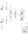
- FIG. 1 is a schematic diagram showing a conventional MAC relay type communication system 100.
- the communication system 100 includes mobile stations UE1 and UE2, a relay station RS, and a base station BS.
- the MAC_PDU 11 transmitted from the mobile station UE1 to the relay station RS includes a MAC header 111 including UE1 identification information (UE_ID) and UE data 112. Further, the MAC_PDU 12 transmitted from the mobile station UE2 to the relay station RS includes a MAC header 121 including identification information (UE_ID) of the mobile station UE2 and UE data 122.
- UE_ID UE1 identification information
- UE_ID identification information
- the relay station RS configures the MAC_PDU 13 by multiplexing these.
- the MAC_PDU 13 includes a MAC header 131 including identification information (Relay_ID) of the relay station RS, a MAC header 111 and UE data 112 of UE1, and a MAC header 121 and UE data 122 of UE2.
- Relay_ID identification information
- MAC_PDUs 11, 12, and 13 are all transmitted with the same scramble code (scramble A).
- the relay station RS includes the identification information of each mobile station UE in one transport block TB, and uses the identification information as a data unit mark.
- the data of each UE is identified by identification information.
- the degree of freedom of control is improved by adding mobile station information to the MAC header.
- the ID information 131 of the relay station RS is included in the control information together with the ID information 111 and 121 of the mobile station UE. For this reason, there has been a problem that communication efficiency is reduced due to an increase in control information.
- the relay station includes an extraction unit that descrambles signals from a plurality of mobile stations and extracts identification information of a physical layer of the mobile station, and a MAC layer that is a data link layer that identifies the identification information of the physical layer And a multiplexing unit that constitutes a protocol data unit including MAC layer identification information of the plurality of mobile stations in a header and including service data units of signals from the plurality of mobile stations.
- a relay station includes identification information of a MAC layer that is a data link layer of a plurality of mobile stations in a header, and is included in a signal from a base station that includes service data units of signals from the plurality of mobile stations.
- a separation unit that converts the identification information of the MAC layer into the identification information of the physical layer and separates the service data unit corresponding to each mobile station.
- a relay method for relaying signals from a plurality of mobile stations to a base station includes extracting physical layer identification information of the mobile station from the signals, and identifying the physical layer identification information in a data link layer. Converting into identification information of a certain MAC layer; configuring a protocol data unit including identification information of MAC layers of the plurality of mobile stations in a header and including service data units of signals from the plurality of mobile stations; including.
- the signal in the relay method for relaying a signal from a base station to a plurality of mobile stations, includes identification information of a MAC layer that is a data link layer of the plurality of mobile stations in a header, A service data unit of a signal from a mobile station of the mobile station, converting the identification information of the MAC layer included in the signal into physical layer identification information, and each mobile station to the corresponding service data unit of the physical layer Transmitting a signal with identification information.
- FIG. 1 is a schematic diagram illustrating a conventional MAC relay type communication system.
- FIG. 1 is a schematic diagram illustrating a communication system according to one embodiment. It is the schematic which shows the process in the relay station by one Embodiment. It is the schematic which shows the process in the relay station by one Embodiment following FIG. It is a figure which shows the format of MAC_PDU after UE multiplexing. It is a block diagram which shows the structural example of a base station. It is a block diagram which shows the structural example of relay station RS. It is a block diagram which shows the structural example of the mobile station UE. It is a block diagram which shows the structural example of the MAC_SDU separation part of the relay station shown in FIG. FIG.
- FIG. 8 is a block diagram illustrating a configuration example of a MAC_SDU multiplexing unit of the relay station illustrated in FIG. 7. It is a sequence diagram which shows the registration process between a base station and a relay station at the time of a start-up of a relay station. It is a block diagram which shows the structure of the base station regarding signaling. It is a block diagram which shows the structure of the relay station regarding signaling. It is a flowchart which shows operation
- FIG. 19 is a diagram for describing a throughput constraint condition when the base station intensive scheduler configuration illustrated in FIG. 18 is used. It is a figure which shows the protocol structure at the time of using a base station aggregation type scheduler. It is a figure which shows the protocol structure at the time of using a relay station distributed type scheduler. It is a block diagram which shows the structural example of a relay station at the time of using a relay station distributed type scheduler.
- BS base station RS relay station UE UE1 to n mobile station 601, 616 L2 buffer 602 DL scheduler control signal generator 603 MAC_PDU generator 604 encoder 605 relay PHY_ID scrambler 606 modulator 607 multiplexer 608 RS transmitter 609 duplexer (DUP) 610 Antenna 611 RF receiver 612 Demodulator 613 Relay PHY_ID descrambler 614 Decoder 615 MAC_SDU extractor 701, 717 Antenna 702, 716 Duplexer (DUP) 703, 718 RF receiving unit 704, 719 Separating unit 705 DL scheduler control signal extracting unit 706 UL scheduler control signal extracting unit 707, 720 Demodulating unit 708 Relay station PHY_ID descrambling unit 709, 722 Decoding unit 710 MAC_SDU separating unit 711, 724 Code 712 Mobile station PHY_ID scrambler 713, 726 Modulator 714 Multiplexer 715, 7
- Embodiments of the present invention will be described in detail.
- the following embodiment is applicable to, for example, LTE (Long Term Evolution), LTE-Advanced, and the like.
- FIG. 2 is a schematic diagram illustrating a communication system 200 according to an embodiment.
- the communication system 200 includes mobile stations UE1 and UE2, a relay station RS, and a base station BS.
- the mobile station UE1 adds CRC (Cyclic Redundancy Check) to the transmission data, encodes it, performs modulation by performing scramble 1 of the mobile station UE1, and transmits it as MAC_PDU 21 from the antenna.
- CRC Cyclic Redundancy Check
- the mobile station UE2 adds CRC (CyclicundRedundancy Check) to the transmission data, encodes and modulates the scramble 2 (different from the scramble 1 of the mobile station UE1) of the mobile station UE2, It transmits from an antenna as MAC_PDU22.
- CRC CyclicundRedundancy Check
- PHY_ID the scramble sequence for each UE.
- the relay station RS also appears as one mobile station UE.
- the relay station RS includes the MAC_SDUs of a plurality of mobile stations UE1 and UE2 in one transport block TB, and uses it as a MAC_SDU.
- CRC is added to the MAC_SDU, encoded, and then scrambled S (PHY_ID) indicating the relay station RS is modulated and modulated, and transmitted as MAC_PDU 23 from the antenna.
- the timing of scrambling for each mobile station or each relay station may be before encoding or after encoding.
- the relay station header 231 is generated and attached as the MAC header.
- FIG. 3 is a schematic diagram illustrating processing in the relay station RS according to an embodiment.
- the transmission data 311 and 312 transmitted by the mobile stations UE1 and UE2 are scrambled by a scramble code unique to the mobile station.
- the relay station RS descrambles the UE-specific scramble sequence, and determines that the scramble sequence is correct if the CRC check is successful. Thereby, PHY_ID of each UE can be extracted (steps A1 and A2).
- the scramble sequence applied for descrambling can be specified in advance by training scheduler information at the relay station RS.
- MAC_PDUs 321 and 322 and PHY_IDs 331 and 332 are obtained in the MAC layer for each of the mobile stations UE1 and UE2.
- FIG. 4 is a schematic diagram showing processing in the relay station RS according to the embodiment, following FIG.
- MAC_PDUs 321 and 322 and PHY_IDs 331 and 332 in the MAC layers of the mobile stations UE1 and UE2 are obtained.
- step B For each mobile station UE, conversion from PHY_ID in the PHY layer to UE_ID in the MAC layer is performed (step B).
- This conversion is performed, for example, by searching for UE_ID corresponding to PHY_ID from a table storing PHY_ID and UE_ID in association with each other.
- the searched UE_ID is embedded in the MAC header so that the identification information of the UE specified by the PHY_ID is not lost.
- the MAC_PDU of each UE is multiplexed to generate a new MAC_PDU (step C).
- the signal format 41 in which the UE_ID information 411 and 412 are inserted at the head of the MAC_PDU of each UE is obtained.
- the format 41 shown in FIG. 4 since the MAC_PDU is arranged for each UE, the MAC header and the MAC_SDU are mixed. In order to facilitate transmission by LTE, LTE-Advanced, etc., the format 41 may be further changed to the format 50 in FIG.
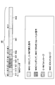
- FIG. 5 is a diagram showing a format 50 of MAC_PDU after UE multiplexing.
- the format 50 includes MAC control elements (MAC-CE (Control Element)) 511 and 512, which are control information of the PHY layer inserted in the MAC layer, corresponding to the mobile stations UE1 and UE2, respectively.
- the MAC control element indicates control information of the physical layer inserted in the MAC layer.
- MAC_SDU LCH Logical Channel
- the C-RNTIs 531 and 532 respectively corresponding to the mobile stations UE1 and UE2 are UE_IDs managed by the base station, and are used as IDs in the MAC layer to the RRC layer.
- C-RNTI is an identifier that the base station uniquely assigns to each user apparatus located in the own cell.
- the format 50 further includes MAC_SDU messages 541 and 542.
- the relay station RS can combine a plurality of UEs at the time of MAC_PDU generation to increase the information included in one transport block TB, thereby improving the coding gain and improving the execution throughput.
- FIG. 6 is a block diagram showing a configuration example of the base station BS.
- An information packet that arrives at the base station BS from a core network is subjected to processing in an upper layer such as concealment and IP header compression, and is then stored in the L2 buffer 601 corresponding to the destination UE.
- an upper layer such as concealment and IP header compression
- the DL scheduler control signal generation unit 602 generates a control signal that gives a transmission opportunity to each UE according to an appropriate algorithm.
- FIG. 6 shows the flow of information packets transmitted from the base station BS to the UE via the relay station RS. Therefore, the DL scheduler control signal generation unit 602 instructs the MAC_PDU generation in consideration of the information packet information amount to be allocated to the relay station RS and the information packet amount of each UE via the relay station RS distributed from the information amount.
- the MAC_PDU generation unit 603 reads information packets from the L2 buffer 601 for each transmitted information amount (transport block TB) according to the control signal of the DL scheduler control signal generation unit 602, and generates MAC_PDU according to a predetermined format.
- the MAC_PDU generation unit 603 adds MAC header information including UE_ID information, multiplexes a plurality of UEs to generate one MAC_PDU, and sends the MAC_PDU to the encoding unit 604.
- the encoding unit 604 performs error correction encoding according to the propagation path between the base station BS and the relay station RS, and sends it to the scramble unit 605.
- the scramble unit 605 scrambles the relay station RS and sends it to the modulation unit 606.
- the modulation unit 606 performs appropriate modulation and sends it to the multiplexing unit 607.
- the multiplexing unit 607 multiplexes the control signal of the DL scheduler control signal generation unit 602 and the control signal of the uplink (UL) scheduler control signal generation unit 617 and sends the multiplexed signal to the RF transmission unit 608.
- the RF transmission unit 608 performs up-conversion to an RF (Radio frequency) band, and transmits from the antenna 610 via a duplexer (DUP) 609.
- DUP duplexer
- the signal received by the antenna 610 is sent to the RF receiving unit 611 via the duplexer 609.
- the RF receiving unit 611 down-converts the received signal into a base band (Base Band) band, and sends it to the demodulating unit 612.
- the demodulation unit 612 performs appropriate demodulation based on the UL schedule information commanded in the past, and sends it to the descrambling unit 613.
- the descrambling unit 613 performs descrambling for confirming the transfer from the relay station RS to the base station BS, and sends the descramble to the decoding unit 614.
- the decoding unit 614 performs error correction decoding and sends it to the MAC_SDU extraction unit 615.
- the MAC_SDU extraction unit 615 performs a process of extracting the MAC_SDU from the correctly received MAC_PDU. And based on UE_ID information contained in the MAC header, information is stored in the correct place of L2 buffer 616 for every UE.
- the L2 buffer 616 transfers it to the upper layer.
- the information output from the L2 buffer 616 is output to a core network (not shown) after being subjected to processing such as deciphering and IP header expansion.
- an L2 buffer is provided for each UE.
- a single L2 buffer may be used for a plurality of UEs.
- FIG. 7 is a block diagram showing a configuration example of the relay station RS.
- the signal received by the antenna 701 is sent to the RF receiving unit 703 via a duplexer (DUP) 702.
- DUP duplexer
- the RF receiving unit 703 down-converts the received signal to the baseband and sends it to the separating unit 704.
- the separation unit 704 reads out the DL scheduler information and the UL scheduler information and sends them to the DL scheduler control signal extraction unit 705 and the UL scheduler control signal extraction unit 706.
- the demodulation unit 707 demodulates the received signal for the relay station based on the read DL scheduler information, and sends it to the RS_PHY_ID descrambling unit 708.
- the RS_PHY_ID descrambling unit 708 performs descrambling for confirming transfer from the base station BS to the relay station RS, and sends the descrambled data to the decoding unit 709.
- the decoding unit 709 performs error correction decoding and sends it to the MAC_SDU separation unit 710. If the decoding unit 709 passes the CRC check, the MAC_PDU has been correctly received.
- the MAC_SDU demultiplexing unit 710 refers to the MAC header information, separates the MAC_SDU from the MAC_PDU, and performs a process of separating signals for the relay station RS and each UE. Here, if there is a signal for the relay station RS, it is transferred to the upper layer.
- the encoding unit 711 performs error correction encoding on the received signal separated for each UE in accordance with the propagation path between the relay station and the UE, and sends the received signal to the UE_PHY_ID scrambling unit 712.
- the UE_PHY_ID scrambler 712 scrambles the UE and sends it to the modulator 713.
- the modulation unit 713 performs appropriate modulation and sends it to the multiplexing unit 714.
- the multiplexing unit 714 multiplexes the control signal from the DL scheduler control signal extraction unit 705 and the control signal from the UL scheduler control signal extraction unit 706 and sends the multiplexed signal to the RF transmission unit 715.
- the RF transmission unit 715 performs up-conversion to the RF band and transmits from the antenna 717 via the duplexer (DUP) 716.
- DUP duplexer
- the signal received by the antenna 717 is sent to the RF receiving unit 718 via a duplexer (DUP) 716.
- DUP duplexer
- the RF receiver 718 down-converts the received signal to the baseband and sends it to the separator 719.
- the separation unit 719 separates each UE based on the UL schedule information commanded in the past, and sends it to the demodulation unit 720.
- the demodulator 720 performs appropriate demodulation on each UE and sends it to the UE_PHY_ID descrambler 721.
- the UE_PHY_ID descrambling unit 721 performs descrambling for confirming the transfer from the UE to the relay station, and sends the descrambling to the decoding unit 722.
- the decoding unit 722 performs error correction decoding and sends it to the MAC_PDU multiplexing unit 723. If the CRC check is passed, the MAC_PDU is correctly received.
- the MAC_PDU multiplexing unit 723 performs UE multiplexing with all the UEs that pass the CRC check as one MAC_PDU, and sends the result to the encoding unit 724. Note that if there is a signal to be sent from the upper layer of the relay station RS to the base station BS, the MAC_PDU multiplexing unit 723 also multiplexes this. Multiplexing is performed by including information corresponding to UE_PHY_ID in the MAC header so that the UE can be identified.
- the encoding unit 724 performs error correction encoding according to the propagation path from the relay station RS to the base station BS, and sends it to the RS_PHY_ID scramble unit 725.
- the RS_PHY_ID scramble unit performs scramble indicating that the information is information from the relay station RS to the base station BS, and sends the scramble to the modulation unit 726.
- the modulation unit 726 performs appropriate modulation and sends it to the RF transmission unit 727.
- the RF transmission unit 727 up-converts the transmission signal to the RF band and transmits it from the antenna 701 via the duplexer 702.
- FIG. 8 is a block diagram illustrating a configuration example of the mobile station UE.
- the signal received by the antenna 801 is sent to the RF receiver 803 via the duplexer 802.
- the RF receiving unit 803 down-converts the received signal to the baseband and sends it to the separating unit 804.
- the separation unit 804 reads the DL scheduler information and the UL scheduler information and sends them to the demodulation unit 807.
- the DL scheduler information and the UL scheduler information are sent to the DL scheduler control signal extraction unit 805 and the UL scheduler control signal extraction unit 806, respectively.
- the demodulating unit 807 performs demodulation for the own device based on the read DL scheduler information, and sends it to the UE_PHY_ID descrambling unit 808.
- the UE_PHY_ID descrambling unit 808 performs descrambling for confirming the transfer from the relay station RS to the UE, and sends the descramble to the decoding unit 809.
- the decoding unit 809 performs error correction decoding and sends it to the MAC_SDU extraction unit 810. If the CRC check is passed, it means that the MAC_PDU has been correctly received.
- the information packet generated from the upper layer is subjected to processing such as concealment and IP header compression to be converted into MAC_SDU.
- the MAC_PDU generation unit 811 generates MAC_PDU by bundling MAC_SDUs by the amount of information that can be transmitted instructed by the UL scheduler, and sends the MAC_PDU to the encoding unit 812.
- the encoding unit 812 performs error correction encoding in accordance with the propagation path from the mobile station UE to the relay station RS, and sends it to the UE_PHY_ID scrambler 813.
- the UE_PHY_ID scrambler 813 scrambles the UE for the relay station and sends the scramble to the modulator 814.
- the modulation unit 814 performs appropriate modulation and sends it to the RF transmission unit 815.
- the RF transmission unit 815 performs up-conversion to RF and transmits from the antenna via a duplexer (DUP) 802.
- DUP duplexer
- FIG. 9 is a block diagram illustrating a configuration example of the MAC_SDU separation unit 710 of the relay station RS illustrated in FIG.
- the MAC_PDU that has passed the CRC check is input to the MAC header analysis unit 901.
- the MAC header analysis unit 901 analyzes the MAC header of the input MAC_PDU and sends it to the UE_ID extraction unit 902.
- the UE_ID extraction unit 902 extracts the UE_ID included in the MAC header and the MAC_PDU corresponding to the UE_ID for each UE.
- the UE_ID is sent to the ID conversion unit 903 for each UE.
- MAC_PDU is sent to the encoding part 711 (FIG. 7) for every UE.
- the ID conversion unit 903 refers to the conversion table 904 and converts UE_ID into PHY_ID used as scramble. And this PHY_ID is sent to the encoding part 711 (FIG. 7) for every UE.
- FIG. 10 is a block diagram illustrating a configuration example of the MAC_SDU multiplexing unit 723 of the relay station RS illustrated in FIG.
- the MAC_SDU multiplexing unit 723 receives a MAC_PDU for each user that has passed the CRC check and a PHY_ID corresponding to the MAC_PDU.
- the PHY_ID is converted by the ID conversion unit 1001 into a UE_ID that can be authenticated in the MAC layer using the conversion table 1002.
- the converted UE_ID and MAC_PDU are input to the MAC_PDU generation unit 1003 for each user.
- the PDU generation unit 1003 multiplexes all corresponding UEs into one MAC_PDU using the format described with reference to FIG. 5 and includes the UE_ID in the MAC header, and sends the multiplexed UE to the encoding unit 724.
- the MAC_SDU multiplexing unit 723 can perform the UE multiplexing described with reference to FIGS. [Relay station recognition] Next, recognition of the relay station RS will be described.
- the relay station RS is recognized as a special mobile station UE when viewed from the base station BS.
- the base station BS recognizes the relay station RS and starts communication. Preparation is necessary.
- the relay station RS When the relay station RS starts up, it makes an RRC connection request to the base station BS by the RACH process in the same manner as an ordinary mobile station UE, and then performs communication settings for the relay station.
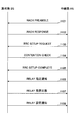
- FIG. 11 is a sequence diagram showing a registration process between the base station BS and the relay station RS when the relay station RS starts up.
- the relay station RS autonomously transmits a RACH preamble (RACH preamble) to the base station Bs (step 1101).
- RACH preamble a RACH preamble
- the base station BS When the base station BS senses the RACH preamble, it returns a RACH response corresponding to the traffic if there is a margin (step 1102).
- the relay station RS When the relay station RS transmits the RACH preamble, it waits for a RACH response. When a RACH response is received within a predetermined time, it is recognized that transmission is permitted, and an RRC setup request (RRC setup Request) is transmitted with the network ID equivalent of the mobile station UE (step 1103).
- RRC setup Request RRC setup Request
- the base station BS When receiving the RRC setup request, the base station BS returns a contention check including the network ID equivalent of the mobile station UE (Step 1104). Since this contention check notifies the ID of a single mobile station UE, it is possible to select only one UE even if other mobile stations UE are crossed during the RACH procedure (RACH procedure). Therefore, it is called Contention Check (competition check).
- the relay station RS transmits an RRC setup request complete (RRC setup request Complete) to the base station BS in response to the RRC setup request (RRC setup request) in the RACH procedure (RACH procedure) (step 1105).
- the relay station RS transmits a relay designation notification indicating that the local station is a relay station (step 1106).
- the base station BS Upon receiving this notification, the base station BS returns a relay designation response indicating that the communication partner is recognized as the relay station RS (step 1107).
- the base station BS transmits setting information required by the relay station RS (MCS between the base station and the relay station, transmission power of the relay station, carrier frequency after relay, etc.) as a relay setting notification (Ste 1108).
- the relay station RS functions as a relay station upon receiving this setting.
- FIG. 12 is a block diagram showing the configuration of the base station BS related to signaling.
- the signal received by the antenna 1201 is sent to the PHY 1203 via the duplexer 1202.
- the PHY 1203 extracts the MAC_SDU from the received signal and sends it to the upper layer receiving unit 1204.
- the upper layer receiving unit 1204 extracts the control command of the radio unit from the received MAC_SDU.
- the base station BS implements the following processing circuit in order to recognize the relay station RS and start up correctly based on the extracted control command.
- the Relay designation receiving unit 1205 receives the Relay designation notification message that the relay station RS notifies after the RACH process, from the control command extracted by the upper layer receiving unit 1204.
- the relay initial setting unit 1206 is necessary in the relay station RS in consideration of the radio state with the relay station RS and the installation status of the surrounding base stations and relay stations in accordance with the relay designation notification message received by the relay designation receiving unit 1205. Determine the setting to be
- the relay response transmission unit 1207 returns a response (Relay designation response) indicating that the relay designation notification has been received from the relay station RS to the relay station RS.
- the relay station initial setting value (relay setting notification) determined by the relay initial setting unit 1206 is sent to the upper layer transmission unit 1208.
- the higher layer transmission unit 1208 uses the response from the Relay response transmission unit 1207 and the Relay station initial setting value as MAC_SDU, generates a MAC_PDU according to the wireless state, and sends it to the PHY 1209.
- the MAC_PDU is converted into a signal format by the PHY 1209 and transmitted from the antenna 1201 via the duplexer (DUP) 1202.
- DUP duplexer
- FIG. 13 is a block diagram illustrating a configuration of a relay station related to signaling.
- the Relay designation transmitting unit 1301 transmits information indicating that the local station is not a normal UE but a relay station.
- the upper layer transmission unit 1302 uses the information as MAC_SDU and generates MAC_PDU according to the radio state.
- the PHY 1303 converts the MAC_PDU generated by the higher layer transmission unit 1302 into a signal format and transmits the signal from the antenna 1305 via the duplexer (DUP) 1304.
- DUP duplexer
- a signal received by the antenna 1305 is sent to the PHY 1306 via a duplexer (DUP) 1304.
- DUP duplexer
- the PHY 1306 extracts the MAC SDU from the received signal and sends it to the upper layer receiving unit 1307.
- the upper layer receiving unit 1307 extracts the control command of the radio unit from the MAC_SDU.
- the relay station implements the following processing circuit in order to recognize the base station BS based on the extracted control command and start up correctly.
- the Relay response receiving unit 1308 receives a response (Relay designation response) of the base station BS that the Relay designation notification from the relay station RS has been received.
- PHY_ID As a relay station is assigned, and PHY_ID as a relay station is applied instead of PHY_ID as a communication terminal.
- the relay station setting reception unit 1309 receives the relay station initial setting value that follows the relay designation response, and sets the setting value in its own device. Thereby, relay station RS starts the operation
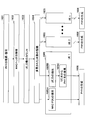
- FIG. 14 is a flowchart showing operations of the base station BS, the relay station RS, and the mobile station UE during downlink.
- the base station BS extracts transmission data from the L2 buffer provided for each UE (step 1401), and generates a MAC_PDU in which transmission data for each UE is multiplexed (step 1402).
- a PHY is generated from this MAC_PDU (step 1403) and transmitted as a transmission signal (step 1404).
- the relay station RS receives the transmission signal transmitted by the base station BS (step 1405), and demodulates and decodes (step 1406).
- MAC_SDU is separated for each mobile station UE from the demodulated / decoded received data (step 1407), PHY is generated (step 1408), and transmitted as a transmission signal (step 1409).
- Each mobile station UE receives a transmission signal addressed to itself from the relay station RS (step 1410), and demodulates and decodes the PHY (step 1411).
- MAC_SDU is extracted from the demodulated / decoded received data (step 1412), and the received data is stored in the L2 buffer of the own station (step 1413).
- FIG. 15 is a flowchart showing operations of the mobile station UE, the relay station RS, and the base station BS during uplink.
- Each mobile station UE1 to UEn extracts transmission data from its own L2 buffer (step 1501), and generates a MAC_PDU (step 1502).
- a PHY is generated from this MAC_PDU (step 1503) and transmitted as a transmission signal (step 1504).
- the relay station RS receives the transmission signals transmitted by the mobile stations UE1 to UEn (step 1505), demodulates and decodes the PHY, and obtains MAC_SDU (step 1506).
- the obtained MAC_SDU is multiplexed to generate a MAC_PDU (step 1507).
- a PHY is generated from the generated MAC_PDU (step 1508) and transmitted as a transmission signal (step 1509).
- the base station BS receives the transmission signal of the relay station RS (step 1510), and demodulates and decodes the PHY (step 1511). Then, the MAC_SDU for each mobile station UE is extracted from the demodulated / decoded PHY, and the received data is stored in the L2 buffer provided in each mobile station UE (step 1513).
- FIG. Will be described in detail with reference to FIG.
- FIG. 16 is a flowchart showing separation of mobile stations UE and replacement of IDs in the MAC layer during downlink.
- the relay station RS demodulates and decodes the PHY received from the base station BS (step 1601), and analyzes the MAC header included in the received data (step 1602). Then, the number of UE_IDs of the mobile station UE multiplexed on the received data is counted (step 1603), and the number of multiplexed mobile stations UE is recognized (step 1604).
- the relay station RS extracts MAC_PDU for each multiplexed mobile station UE (step 1605A).
- UE_ID is extracted (step 1605B), and UE_ID is converted into PHY_ID (step 1605C).
- steps 1601A to 1605C are performed for each mobile station UE (step 1605).
- the relay station RS generates a PHY for each multiplexed mobile station UE based on the extracted MAC_PDU and the converted PHY_ID (step 1606).
- FIG. Will be described in detail with reference to FIG.
- FIG. 17 is a flowchart showing multiplexing of mobile stations UE and replacement of IDs in the MAC layer during uplink.
- the relay station RS demodulates and decodes the PHY received from each mobile station UE (step 1701A).
- MAC_SDU is extracted from the demodulated / decoded received data (step 1701B), and in parallel therewith, PHY_ID is extracted (step 1701C) and PHY_ID is converted to UE_ID (step 1701D).
- steps 1701A to 1701D are performed for each mobile station UE (step 1701).
- the relay station RS generates a MAC_PDU based on the extracted MAC_SDU and the converted UE_ID (step 1702), and generates a PHY from the MAC_PDU (step 1703).
- the base station BS, the relay station RS, and the mobile station UE described with reference to FIGS. 6 to 8 have a configuration in which the scheduler function is integrated in the base station. A part of the scheduler function can be distributed to the relay stations RS. Hereinafter, the configuration of the scheduler will be described.
- FIG. 18 is a block diagram showing a configuration of a base station intensive scheduler 1800.
- the scheduler 1800 includes a scheduler unit 1801 that performs resource allocation according to the propagation path between the base station (eNB) and the relay station (Relay) as a master.
- the scheduler part 1802 which performs the resource allocation according to a propagation path with respect to the relay station (Relay) and each mobile station UE by making the resource allocated by the scheduler part 1801 into an upper limit.
- scheduler control signal unit 1803 for multiplexing and notifying a control signal from the scheduler unit 1801 of the base station and the relay station and a control signal from the scheduler unit 1802 of the relay station and the mobile station UE.
- FIG. 19 is a diagram for explaining a constraint condition of throughput when the base station intensive scheduler configuration shown in FIG. 18 is adopted.
- FIG. 20 is a diagram showing a protocol configuration when a base station intensive scheduler is used.
- the scheduler multiplexes and notifies in a two-layer configuration in consideration thereof.
- a relay station distributed scheduler that distributes a part of the scheduler function to relay stations for the above base station intensive scheduler will be described.
- FIG. 21 is a diagram showing a protocol configuration when a relay station distributed scheduler is used.
- the MAC Since the base station and the relay station each have a scheduling function, the MAC is completely terminated at the relay station as shown in FIG. In order to perform completely independent scheduling, the relay station needs a buffer.
- FIG. 22 is a block diagram showing a configuration example of the relay station RS when the relay station distributed scheduler is used.
- the relay station RS shown in FIG. 22 has L2 buffers (L2 Buffers) 2201 and 2202 for each of the mobile stations UE1 to UEn, between the base station BS and the relay station RS, and between the relay station RS and each mobile station. It is possible to operate with completely independent scheduling between the stations UE1 to UEn.
- L2 Buffers L2 Buffers
- the base station side has DL / UL scheduler control signal extraction sections 2203 and 2204, and uses the scheduler control signal from the base station.
- the mobile station side has DL / UL scheduler control signal generation units 2205 and 2206, and operates by scheduling independent of the base station side.
- the relay station RS can allocate resources in consideration of the buffer amount of the L2 buffer (L2 Buffer) and QoS.
- the present invention is applicable to a relay station, a base station, a relay method, and a communication method in a wireless communication network.
Abstract
L'invention porte sur une station de relais qui comprend une section d'extraction pour extraire des informations de discrimination d'une couche physique d'une station mobile à partir de signaux provenant d'une pluralité de stations mobiles, et une section de multiplexage qui convertit les informations de discrimination de la couche physique en informations de discrimination d'une couche MAC, qui est une couche de liaison de données, et qui crée une unité de données de protocole consistant en un en-tête comprenant les informations de discrimination de la couche MAC de la pluralité de stations mobiles et une unité de données de service des signaux provenant de la pluralité de stations mobiles.
Priority Applications (4)
| Application Number | Priority Date | Filing Date | Title |
|---|---|---|---|
| JP2011506892A JP5304889B2 (ja) | 2009-03-31 | 2009-03-31 | 無線通信ネットワークにおける中継局、基地局、中継方法、及び通信方法 |
| PCT/JP2009/056676 WO2010113267A1 (fr) | 2009-03-31 | 2009-03-31 | Station de relais, station de base, procédé de relais et procédé de communication dans un réseau de communication sans fil |
| EP09842622.4A EP2416618A4 (fr) | 2009-03-31 | 2009-03-31 | Station de relais, station de base, procédé de relais et procédé de communication dans un réseau de communication sans fil |
| US13/240,491 US20120008547A1 (en) | 2009-03-31 | 2011-09-22 | Relay station, base station, relay method and communication method used in wireless communications network |
Applications Claiming Priority (1)
| Application Number | Priority Date | Filing Date | Title |
|---|---|---|---|
| PCT/JP2009/056676 WO2010113267A1 (fr) | 2009-03-31 | 2009-03-31 | Station de relais, station de base, procédé de relais et procédé de communication dans un réseau de communication sans fil |
Related Child Applications (1)
| Application Number | Title | Priority Date | Filing Date |
|---|---|---|---|
| US13/240,491 Continuation US20120008547A1 (en) | 2009-03-31 | 2011-09-22 | Relay station, base station, relay method and communication method used in wireless communications network |
Publications (1)
| Publication Number | Publication Date |
|---|---|
| WO2010113267A1 true WO2010113267A1 (fr) | 2010-10-07 |
Family
ID=42827600
Family Applications (1)
| Application Number | Title | Priority Date | Filing Date |
|---|---|---|---|
| PCT/JP2009/056676 WO2010113267A1 (fr) | 2009-03-31 | 2009-03-31 | Station de relais, station de base, procédé de relais et procédé de communication dans un réseau de communication sans fil |
Country Status (4)
| Country | Link |
|---|---|
| US (1) | US20120008547A1 (fr) |
| EP (1) | EP2416618A4 (fr) |
| JP (1) | JP5304889B2 (fr) |
| WO (1) | WO2010113267A1 (fr) |
Cited By (6)
| Publication number | Priority date | Publication date | Assignee | Title |
|---|---|---|---|---|
| WO2013051575A1 (fr) * | 2011-10-06 | 2013-04-11 | 株式会社エヌ・ティ・ティ・ドコモ | Station de base et procédé de commande de communication |
| WO2013051578A1 (fr) * | 2011-10-06 | 2013-04-11 | 株式会社エヌ・ティ・ティ・ドコモ | Station de base et procédé de commande de communication |
| JP2013176167A (ja) * | 2013-06-12 | 2013-09-05 | Ntt Docomo Inc | 基地局及び通信制御方法 |
| JP2013544463A (ja) * | 2010-10-25 | 2013-12-12 | エスシーエー アイピーエルエー ホールディングス インコーポレイテッド | 通信システム及び方法 |
| JP2019519946A (ja) * | 2016-03-30 | 2019-07-11 | グァンドン オッポ モバイル テレコミュニケーションズ コーポレーション リミテッドGuangdong Oppo Mobile Telecommunications Corp., Ltd. | 中継伝送方法 |
| JP2019520727A (ja) * | 2016-06-03 | 2019-07-18 | グァンドン オッポ モバイル テレコミュニケーションズ コーポレーション リミテッドGuangdong Oppo Mobile Telecommunications Corp., Ltd. | 中継伝送方法及び装置 |
Families Citing this family (11)
| Publication number | Priority date | Publication date | Assignee | Title |
|---|---|---|---|---|
| US20130155918A1 (en) * | 2011-12-20 | 2013-06-20 | Nokia Siemens Networks Oy | Techniques To Enhance Header Compression Efficiency And Enhance Mobile Node Security |
| TWI572230B (zh) * | 2012-11-23 | 2017-02-21 | Chunghwa Telecom Co Ltd | Energy saving mechanism system and method for wireless relay network |
| KR20140079525A (ko) * | 2012-12-14 | 2014-06-27 | 한국전자통신연구원 | 중계기를 포함한 통신 시스템에서 기지국과 단말의 통신 방법 |
| JP5696186B2 (ja) * | 2013-08-09 | 2015-04-08 | 株式会社Nttドコモ | 移動局及び無線基地局 |
| KR102139721B1 (ko) * | 2013-08-29 | 2020-07-30 | 삼성전자주식회사 | 다중 경로 프로토콜에서 이중으로 네트워크 코딩을 적용하는 방법 및 그 장치 |
| FR3030992B1 (fr) * | 2014-12-23 | 2016-12-23 | Thales Sa | Systeme et procede de transmission de donnees utilisant conjointement une liaison terrestre et une liaison satellitaire |
| EP3300422A4 (fr) | 2015-05-22 | 2018-09-26 | NTT DoCoMo, Inc. | Station de base |
| KR102208870B1 (ko) * | 2015-10-08 | 2021-01-27 | 노벨리스 인크. | 알루미늄 열간 가공의 최적화 |
| US10764961B2 (en) * | 2016-03-30 | 2020-09-01 | Guangdong Oppo Mobile Telecommunications Corp., Ltd. | Relay transmission method and device |
| US11177902B2 (en) * | 2017-01-16 | 2021-11-16 | Drexel University | Physical gate based preamble obfuscation for securing wireless communication |
| CN113114328B (zh) * | 2021-03-19 | 2023-03-31 | 中国联合网络通信集团有限公司 | 一种信号中继方法、信号识别方法、装置及设备 |
Citations (4)
| Publication number | Priority date | Publication date | Assignee | Title |
|---|---|---|---|---|
| JP2005501494A (ja) * | 2001-08-21 | 2005-01-13 | ノキア コーポレイション | 通信ネットワーク内のデータ送信 |
| WO2007053840A2 (fr) * | 2005-10-31 | 2007-05-10 | Qualcomm Incorporated | Transmission efficace sur un canal de donnees partage pour des communications sans fil |
| JP2008099283A (ja) | 2006-10-13 | 2008-04-24 | Fujitsu Ltd | 無線通信システム |
| JP2008104096A (ja) | 2006-10-20 | 2008-05-01 | Kddi Corp | 無線中継システムおよびそのメッセージ交換方法 |
Family Cites Families (12)
| Publication number | Priority date | Publication date | Assignee | Title |
|---|---|---|---|---|
| CA2584962C (fr) * | 2004-10-20 | 2013-09-24 | T-Mobile International Ag & Co. Kg | Systeme de radiocommunications de zone etendue cellulaire avec cellules a relais ameliores |
| KR20070038657A (ko) * | 2005-10-06 | 2007-04-11 | 삼성전자주식회사 | 다중 홉 릴레이 방식을 사용하는 광대역 무선 접속 통신시스템에서 중계국 기능 교섭 장치 및 방법 |
| JP2009514325A (ja) * | 2005-10-26 | 2009-04-02 | テレフオンアクチーボラゲット エル エム エリクソン(パブル) | 移動通信ネットワークにおける方法および装置 |
| BRPI0620674A2 (pt) * | 2005-12-13 | 2011-11-22 | Lg Electronics Inc | método de comunicação usando estação retransmissora em um sistema de comunicação móvel |
| KR100901137B1 (ko) * | 2006-01-03 | 2009-06-04 | 삼성전자주식회사 | 다중 홉 릴레이 방식 무선 접속 통신시스템에서 연결식별자관리 방법 및 장치 |
| US8576882B2 (en) * | 2006-05-11 | 2013-11-05 | Blackberry Limited | Media access control protocol for multi-hop network systems and method therefore |
| CN101047431B (zh) * | 2006-06-22 | 2011-02-02 | 华为技术有限公司 | 在含有中继站的通信系统中实现混合自动重传的方法 |
| EP2041910A4 (fr) * | 2006-07-06 | 2013-05-22 | Apple Inc | Sécurité de point d'accès sans fil pour réseaux à bonds multiples |
| EP1916782A1 (fr) * | 2006-10-26 | 2008-04-30 | Nortel Networks Limited | Structure de trame pour un système sans fil à sauts multiples |
| US8717964B2 (en) * | 2007-03-09 | 2014-05-06 | Motorola Solutions, Inc. | Wireless wide-area communication network multihop relay station management |
| KR101473008B1 (ko) * | 2007-08-13 | 2014-12-17 | 엘지전자 주식회사 | VoIP 패킷을 전송하는 방법 |
| EP2043391A1 (fr) * | 2007-09-25 | 2009-04-01 | Nokia Siemens Networks Oy | Omission de l'identifiant de l'UE sur un processus RACH amélioré |
-
2009
- 2009-03-31 EP EP09842622.4A patent/EP2416618A4/fr not_active Withdrawn
- 2009-03-31 JP JP2011506892A patent/JP5304889B2/ja not_active Expired - Fee Related
- 2009-03-31 WO PCT/JP2009/056676 patent/WO2010113267A1/fr active Application Filing
-
2011
- 2011-09-22 US US13/240,491 patent/US20120008547A1/en not_active Abandoned
Patent Citations (4)
| Publication number | Priority date | Publication date | Assignee | Title |
|---|---|---|---|---|
| JP2005501494A (ja) * | 2001-08-21 | 2005-01-13 | ノキア コーポレイション | 通信ネットワーク内のデータ送信 |
| WO2007053840A2 (fr) * | 2005-10-31 | 2007-05-10 | Qualcomm Incorporated | Transmission efficace sur un canal de donnees partage pour des communications sans fil |
| JP2008099283A (ja) | 2006-10-13 | 2008-04-24 | Fujitsu Ltd | 無線通信システム |
| JP2008104096A (ja) | 2006-10-20 | 2008-05-01 | Kddi Corp | 無線中継システムおよびそのメッセージ交換方法 |
Non-Patent Citations (1)
| Title |
|---|
| See also references of EP2416618A4 * |
Cited By (11)
| Publication number | Priority date | Publication date | Assignee | Title |
|---|---|---|---|---|
| JP2013544463A (ja) * | 2010-10-25 | 2013-12-12 | エスシーエー アイピーエルエー ホールディングス インコーポレイテッド | 通信システム及び方法 |
| WO2013051575A1 (fr) * | 2011-10-06 | 2013-04-11 | 株式会社エヌ・ティ・ティ・ドコモ | Station de base et procédé de commande de communication |
| WO2013051578A1 (fr) * | 2011-10-06 | 2013-04-11 | 株式会社エヌ・ティ・ティ・ドコモ | Station de base et procédé de commande de communication |
| JP2013085032A (ja) * | 2011-10-06 | 2013-05-09 | Ntt Docomo Inc | 基地局及び通信制御方法 |
| JP2013085031A (ja) * | 2011-10-06 | 2013-05-09 | Ntt Docomo Inc | 基地局及び通信制御方法 |
| JP2013176167A (ja) * | 2013-06-12 | 2013-09-05 | Ntt Docomo Inc | 基地局及び通信制御方法 |
| JP2019519946A (ja) * | 2016-03-30 | 2019-07-11 | グァンドン オッポ モバイル テレコミュニケーションズ コーポレーション リミテッドGuangdong Oppo Mobile Telecommunications Corp., Ltd. | 中継伝送方法 |
| US11140729B2 (en) | 2016-03-30 | 2021-10-05 | Guangdong Oppo Mobile Telecommunications Corp., Ltd. | Relay transmission method and device |
| JP2019520727A (ja) * | 2016-06-03 | 2019-07-18 | グァンドン オッポ モバイル テレコミュニケーションズ コーポレーション リミテッドGuangdong Oppo Mobile Telecommunications Corp., Ltd. | 中継伝送方法及び装置 |
| US10841789B2 (en) | 2016-06-03 | 2020-11-17 | Guangdong Oppo Mobile Telecommunications Corp., Ltd. | Method and device for relay transmission |
| US11405773B2 (en) | 2016-06-03 | 2022-08-02 | Guangdong Oppo Mobile Telecommunications Corp., Ltd. | Method and device for relay transmission |
Also Published As
| Publication number | Publication date |
|---|---|
| EP2416618A4 (fr) | 2017-01-25 |
| JP5304889B2 (ja) | 2013-10-02 |
| JPWO2010113267A1 (ja) | 2012-10-04 |
| US20120008547A1 (en) | 2012-01-12 |
| EP2416618A1 (fr) | 2012-02-08 |
Similar Documents
| Publication | Publication Date | Title |
|---|---|---|
| JP5304889B2 (ja) | 無線通信ネットワークにおける中継局、基地局、中継方法、及び通信方法 | |
| US20220239444A1 (en) | Wireless telecommunications apparatus and methods | |
| US11503558B2 (en) | Method and apparatus for time synchronization in device-to-device communication | |
| EP3769452B1 (fr) | Procédés et appareils permettant d'utiliser en totalité la longueur d'une opportunité de transmission | |
| EP2214450B1 (fr) | Procédé de communication par canal physique pour l'accès aléatoire dans un système de communication sans fil | |
| CN111247856A (zh) | 新无线电(nr)中侧边链路控制信息(sci)的两阶式设计 | |
| CN109417723A (zh) | 用于发送数据单元的方法和设备 | |
| EP2557883B1 (fr) | Procédé et dispositif de transmission inverse dans un système de communication mobile | |
| CN110959301B (zh) | 在无线通信系统中基于锚载波分配资源的方法和设备 | |
| CN111264080A (zh) | 在无线通信系统中触发发送载波选择的方法和设备 | |
| JP2020520582A (ja) | データユニットを送信する方法及び装置 | |
| EP2333982A1 (fr) | Procédé pour la communication en liaison descendante au moyen d'un signal radio superposé en liaison descendante, station de base et terminal utilisateur correspondant | |
| JP5188870B2 (ja) | 基地局、移動局及び周波数分割多重通信方法 | |
| WO2016175029A1 (fr) | Dispositif de communication sans fil, et terminal d'utilisateur | |
| WO2006110072A1 (fr) | En-tete mac pour multiplexage remontant renforce | |
| US20210235519A1 (en) | Method and apparatus for processing signals by node in wireless communication system | |
| WO2008031354A1 (fr) | Station et procédé d'envoi d'informations de contrôle de répartition | |
| WO2010003275A1 (fr) | Procédé et appareil destinés à traiter une unité de données de protocole dans un réseau sans fil | |
| JP6732185B2 (ja) | ユーザ端末及び制御方法 | |
| CN110463330A (zh) | 一种支持随机接入的用户设备、基站中的方法和装置 | |
| CN115150758A (zh) | 用户设备、基站和通信系统以及通信方法 | |
| CN115884095A (zh) | 一种被用于无线通信中的方法和装置 | |
| CN115119337A (zh) | 一种被用于无线通信中的方法和装置 | |
| JP2010056765A (ja) | 無線通信システム、基地局、移動局および無線通信方法 |
Legal Events
| Date | Code | Title | Description |
|---|---|---|---|
| 121 | Ep: the epo has been informed by wipo that ep was designated in this application |
Ref document number: 09842622 Country of ref document: EP Kind code of ref document: A1 |
|
| WWE | Wipo information: entry into national phase |
Ref document number: 2011506892 Country of ref document: JP |
|
| NENP | Non-entry into the national phase |
Ref country code: DE |
|
| WWE | Wipo information: entry into national phase |
Ref document number: 2009842622 Country of ref document: EP |