EP2416089A1 - Refrigeration device - Google Patents
Refrigeration device Download PDFInfo
- Publication number
- EP2416089A1 EP2416089A1 EP10758181A EP10758181A EP2416089A1 EP 2416089 A1 EP2416089 A1 EP 2416089A1 EP 10758181 A EP10758181 A EP 10758181A EP 10758181 A EP10758181 A EP 10758181A EP 2416089 A1 EP2416089 A1 EP 2416089A1
- Authority
- EP
- European Patent Office
- Prior art keywords
- oil
- compressor
- accumulator
- accumulators
- compressors
- Prior art date
- Legal status (The legal status is an assumption and is not a legal conclusion. Google has not performed a legal analysis and makes no representation as to the accuracy of the status listed.)
- Granted
Links
Images


Classifications
-
- F—MECHANICAL ENGINEERING; LIGHTING; HEATING; WEAPONS; BLASTING
- F25—REFRIGERATION OR COOLING; COMBINED HEATING AND REFRIGERATION SYSTEMS; HEAT PUMP SYSTEMS; MANUFACTURE OR STORAGE OF ICE; LIQUEFACTION SOLIDIFICATION OF GASES
- F25B—REFRIGERATION MACHINES, PLANTS OR SYSTEMS; COMBINED HEATING AND REFRIGERATION SYSTEMS; HEAT PUMP SYSTEMS
- F25B31/00—Compressor arrangements
- F25B31/002—Lubrication
- F25B31/004—Lubrication oil recirculating arrangements
-
- F—MECHANICAL ENGINEERING; LIGHTING; HEATING; WEAPONS; BLASTING
- F25—REFRIGERATION OR COOLING; COMBINED HEATING AND REFRIGERATION SYSTEMS; HEAT PUMP SYSTEMS; MANUFACTURE OR STORAGE OF ICE; LIQUEFACTION SOLIDIFICATION OF GASES
- F25B—REFRIGERATION MACHINES, PLANTS OR SYSTEMS; COMBINED HEATING AND REFRIGERATION SYSTEMS; HEAT PUMP SYSTEMS
- F25B2313/00—Compression machines, plants or systems with reversible cycle not otherwise provided for
- F25B2313/025—Compression machines, plants or systems with reversible cycle not otherwise provided for using multiple outdoor units
- F25B2313/0253—Compression machines, plants or systems with reversible cycle not otherwise provided for using multiple outdoor units in parallel arrangements
-
- F—MECHANICAL ENGINEERING; LIGHTING; HEATING; WEAPONS; BLASTING
- F25—REFRIGERATION OR COOLING; COMBINED HEATING AND REFRIGERATION SYSTEMS; HEAT PUMP SYSTEMS; MANUFACTURE OR STORAGE OF ICE; LIQUEFACTION SOLIDIFICATION OF GASES
- F25B—REFRIGERATION MACHINES, PLANTS OR SYSTEMS; COMBINED HEATING AND REFRIGERATION SYSTEMS; HEAT PUMP SYSTEMS
- F25B2400/00—Component parts or details not otherwise provided for in this subclass
- F25B2400/07—Details of compressors or related parts
- F25B2400/075—Details of compressors or related parts with parallel compressors
-
- F—MECHANICAL ENGINEERING; LIGHTING; HEATING; WEAPONS; BLASTING
- F25—REFRIGERATION OR COOLING; COMBINED HEATING AND REFRIGERATION SYSTEMS; HEAT PUMP SYSTEMS; MANUFACTURE OR STORAGE OF ICE; LIQUEFACTION SOLIDIFICATION OF GASES
- F25B—REFRIGERATION MACHINES, PLANTS OR SYSTEMS; COMBINED HEATING AND REFRIGERATION SYSTEMS; HEAT PUMP SYSTEMS
- F25B2500/00—Problems to be solved
- F25B2500/01—Geometry problems, e.g. for reducing size
-
- F—MECHANICAL ENGINEERING; LIGHTING; HEATING; WEAPONS; BLASTING
- F25—REFRIGERATION OR COOLING; COMBINED HEATING AND REFRIGERATION SYSTEMS; HEAT PUMP SYSTEMS; MANUFACTURE OR STORAGE OF ICE; LIQUEFACTION SOLIDIFICATION OF GASES
- F25B—REFRIGERATION MACHINES, PLANTS OR SYSTEMS; COMBINED HEATING AND REFRIGERATION SYSTEMS; HEAT PUMP SYSTEMS
- F25B43/00—Arrangements for separating or purifying gases or liquids; Arrangements for vaporising the residuum of liquid refrigerant, e.g. by heat
- F25B43/006—Accumulators
-
- F—MECHANICAL ENGINEERING; LIGHTING; HEATING; WEAPONS; BLASTING
- F25—REFRIGERATION OR COOLING; COMBINED HEATING AND REFRIGERATION SYSTEMS; HEAT PUMP SYSTEMS; MANUFACTURE OR STORAGE OF ICE; LIQUEFACTION SOLIDIFICATION OF GASES
- F25B—REFRIGERATION MACHINES, PLANTS OR SYSTEMS; COMBINED HEATING AND REFRIGERATION SYSTEMS; HEAT PUMP SYSTEMS
- F25B43/00—Arrangements for separating or purifying gases or liquids; Arrangements for vaporising the residuum of liquid refrigerant, e.g. by heat
- F25B43/02—Arrangements for separating or purifying gases or liquids; Arrangements for vaporising the residuum of liquid refrigerant, e.g. by heat for separating lubricants from the refrigerant
Definitions
- the present invention relates to a refrigerating device provided with a multiple outdoor machine that uses a plurality of outdoor machine units in combination and particularly to a configuration of an oil circuit that prevents uneven distribution of refrigerator oil among the outdoor machine units constituting the multiple outdoor machine and operation control thereof.
- Methods of appropriately supplying oil (refrigerator oil) to a plurality of compressors include use of a refrigerating device described in Japanese Patent No. 3937884 (Patent Literature 1), for example.
- This refrigerating device is constructed by a refrigerating cycle in which a plurality of compressors connected in parallel, a condenser, a decompressor, an evaporator, and an accumulator are serially connected, provides an oil recovering circuit that recovers excess refrigerator oil in the compressor into the accumulator, holds the refrigerator oil circulating through the refrigerating cycle in the accumulator and provides an operation controller that stops an operation of a target compressor when an oil recovering operation for recovering the refrigerator oil in the compressor into the accumulator.
- an oil return circuit that supplies the refrigerator oil in the accumulator to the compressor is provided.
- Patent Literature 2 a use of a multiple-unit refrigerator provided with one or a plurality of compressors for one outdoor unit in a form in which a plurality of outdoor units are connected in parallel by piping between the units, extending from the outdoor units, has been considered. Moreover, an oil tank that stores oil separated by an oil separator from a high-pressure gas refrigerant discharged from the compressor is made to flow through each outdoor unit in order to equalize oil.
- Patent Literature 2 a method in communication of the oil storage portions installed on the high pressure side of each outdoor machine each other is also disclosed in Patent Literature 2, if the oil storage portion is installed on the low pressure side, a driving force to fluidize the oil is decreased, and equalizing of the oil is difficult, which is a problem.
- the present invention aims to provide a refrigerating device that improves reliability of a refrigerator operation by avoiding oil depletion of a specific outdoor unit and by operating so as to equalize and supply oil to all the compressors when a large-capacity refrigerator provided with an oil storage portion on the low pressure side is constructed and that can be realized inexpensively by combining existing refrigerators.
- a refrigerating device of the present invention is a refrigerating device that forms a refrigerating cycle in which a plurality of outdoor machines, each provided at least with a compressor, a condenser and an accumulator, and an indoor machine provided with decompressing means and an evaporator are connected in parallel by piping, having an oil return pipe that returns refrigerator oil stored in said accumulator to said compressor, an oil equalizing pipe that connects the accumulators to each other, and a controller that controls an operation of said compressor and on/off of an electromagnetic valve deposed on said oil equalizing pipe.
- the refrigerator oil can be equalized and supplied to the compressors of all the outdoor machines, and oil depletion of the compressor can be prevented.
- the refrigerating device can be inexpensively realized by combining conventional refrigerators.
- Fig. 1 is a refrigerant circuit diagram of a refrigerating device 100 according to Embodiment 1 of the present invention.
- the refrigerating device 100 of Embodiment 1 is provided with a plurality of (two in this example) outdoor machines (also referred to as outdoor units) 1a and 1b, and the outdoor machines 1 a and 1 b are connected in parallel with a indoor machine (also referred to as indoor units) 20, which is usually plural, having an expansion valve 21 that is decompressing means and an evaporator 22 by means of a liquid pipeline 23 and a gas pipeline 24.
- a indoor machine also referred to as indoor units
- the outdoor machines 1a and 1b are provided with compressors 2a and 2b, oil separators 3a and 3b, condensers 4a and 4b, accumulators 5a and 5b, and oil regulators 6a and 6b, respectively.
- compressors 2a and 2b oil separators 3a and 3b
- condensers 4a and 4b condensers 4a and 4b
- accumulators 5a and 5b accumulators 5a and 5b
- oil regulators 6a and 6b respectively.
- the accumulators 5a and 5b are connected to each other by an oil equalizing pipe 10 in order to prevent uneven distribution of oil amounts stored in the individual accumulator.
- an electromagnetic valve 12a that opens/closes communication of the oil is provided in the oil equalizing pipe 10.
- end portions 10a and 10b of the equalizing pipe 10 penetrate through and are inserted into the bottom portions of the accumulators 5a and 5b, respectively, and end inlet of the oil equalizing pipe 10 is installed at a predetermined height from (the same height as) the bottom face of each of the accumulators 5a and 5b.
- a gas refrigerant (including refrigerator oil that could not be separated) in the accumulators 5a and 5b is sucked into the compressors 2a and 2b via gas intake pipes 7a and 7b.
- the gas intake pipes 7a and 7b have one ends, which are to be inserted into the accumulators 5a and 5b, formed in the U-shape, and the U-shaped pipe portions have oil return holes 8a and 8b, respectively.
- oil return pipes 13a and 13b that return the oil stored in the accumulators 5a and 5b to the compressors 2a and 2b have one ends that penetrate through and connect to the bottom portion of the accumulators 5a and 5b, while the other ends are connected to the oil regulators 6a and 6b.
- the oil regulators 6a and 6b and the compressors 2a and 2b are connected by oil intake pipes 14a and 14b and pressure equalizing pipes 15a and 15b respectively. Inside the oil regulators 6a and 6b, float valves (not shown) interlocking with floats are provided. If the oil level is not more than the specified height, the float valve is opened, and the oil is supplied to the compressors 2a and 2b. If the oil level reaches the specified height, the float valve is shut off so that oil supply to the compressors 2a and 2b is stopped.
- Reference numeral 30 denotes a controller that controls operations of the compressors 2a and 2b and opening/closing of the electromagnetic valve 12a provided in the oil equalizing pipe 10.
- the compressors 2a and 2b are inverter-type compressors of a low-pressure shell type, in which the inside of a shell such as a scroll is at a low pressure, and has a structure in which the refrigerator oil is held in the compressor shell. Also, in this refrigerating device 100, a required oil amount is an amount obtained by totaling the appropriate oil amount in the compressors 2a and 2b and the oil amount present in each part of the refrigerating device 100, and as an oil amount to be filled, an oil amount larger than this oil amount is filled in advance. The extra oil is stored in the accumulators 5a and 5b.
- an amount of oil taken out from the compressor rapidly increases to the oil level or more, and a compression load is increased.
- the appropriate oil amounts in the compressors 2a and 2b become an oil level corresponding to a sufficient oil amount at which the amount of oil taken out does not rapidly increase and the oil does not become depleted.
- a refrigerant and a refrigerator oil that are soluble with each other are used.
- the refrigerant is R22
- mineral oil is used as the refrigerator oil
- ester oil is used as the refrigerator oil.
- a high-temperature high-pressure gas refrigerant discharged from the compressors 2a and 2b is condensed and liquefied by the condensers 4a and 4b via the oil separators 3a and 3b and then, is decompressed by the expansion valve 21 of the indoor machine 20 via the liquid pipeline 23 and turns into a two-phase refrigerant, is evaporated and gasified by the evaporator 22 and then, enters into the accumulators 5a and 5b of each of the outdoor machines 1 a and 1 b via the gas pipeline 24 and the distributor 25a and moreover, the evaporated and gasified refrigerant is sucked into the compressors 2a and 2b via the gas intake pipes 7a and 7b, forms a circulating refigerating cycle so that the refrigerant and refrigerator
- a flow of the refrigerator oil in the refrigerating device 100 in Embodiment 1 will be described.
- the flow of the refrigerator oil is shown by a broken-line arrow in Fig. 1 .
- Approximately 90% of the refrigerator oil discharged together with the gas refrigerant from the compressors 2a and 2b is separated at the oil separators 3a and 3b.
- the separated refrigerator oil enters the gas intake pipes 7a and 7b via the capillary tube (not shown) and the like and is returned to the compressors 2a and 2b.
- the oil not separated in the oil separators 3a and 3b flows into the accumulators 5a and 5b through the condensers 4a and 4b, the liquid pipeline 23, the expansion valve 21, the evaporator 22, the gas pipeline 24, and the distributor 25a.
- the refrigerator oil and the gas refrigerant are separated from each other, and the separated oil is collected in the bottom portions of the accumulators 5a and 5b.
- the refrigerator oil collected in the accumulators 5a and 5b is supplied to the compressors 2a and 2b from the oil return pipes 13a and 13b via the oil regulators 6a and 6b.
- the pressure equalizing pipes 15a and 15b are connected.
- the extra oil in the refrigerating device is collected in the accumulators 5a and 5b of a low-pressure part.
- the oil not having been separated in the oil separators 3a and 3b circulates through the refrigerant circuit and flows into the outdoor machines 1a and 1b again. However, if there are a plurality of outdoor machines, oil is not evenly distributed in general and amounts of oil to be returned are different among the outdoor machines. If the refrigerating device 100 of the present embodiment is operated for a long hours, stored amounts of excess oil in the accumulators 5a and 5b become different, and the oil in one of the accumulators might become depleted. If the oil in the accumulator 5a is depleted, for example, the oil in the compressor 2a is also depleted, which causes breakage of the compressor.
- the oil equalizing pipe 10 is connected between the accumulator 5a and the accumulator 5b via the electromagnetic valve 12a. Moreover, inflow port positions (end positions) of the end portions 10a and 10b of the oil equalizing pipe 10 are set at a predetermined height from the bottom face of each of the accumulators 5a and 5b. During a usual operation of the compressors 2a and 2b, the electromagnetic valve 12a of the oil equalizing pipe 10 is closed, and the compressors are operated with the oil equalizing pipe 10 that connects the accumulators 5a and 5b closed.
- the usual operation of the compressors 2a and 2b is performed for a predetermined time and the oil equalizing operation is performed in order to decrease the uneven distribution of the oil in the accumulators 5a and 5b before the oil is depleted.
- This oil equalizing operation is performed by the controller 30 in as short a time as possible.
- the compressor does not necessarily have to be stopped during the oil equalizing operation, but it may be performed after the compressor is stopped. The oil equalizing operation method will be described later.
- oil is unevenly distributed in the accumulators 5a and 5b.
- the oil in the accumulator 5b is supplied to the compressor 2b via the oil return pipe 13b and the oil regulator 6b, and the oil in the accumulator 5b begins to become depleted.
- the oil equalizing operation is performed before the oil is depleted.
- Methods of determining the timing at which to start the oil equalizing operation are (1) a method of determining the timing using an elapsed time of a usual operation; and (2) a method of determining the timing using a total frequency (total of driving frequencies of the compressors) of the compressors 2a and 2b.
- the oil equalizing operation is started when the elapsed time or the total frequency reaches a set value or more.
- the oil equalizing operation might involve control of an oil return mode.
- the oil return mode is an operation mode in which oil remained outside the outdoor machine system (indoor machines, extension pipelines and the like) is recovered, and the oil is recovered by stopping the compressor related to oil depletion and circulating the refrigerant.
- the oil equalizing operation method will be described.
- the electromagnetic valve 12a of the oil equalizing pipe 10 is opened, and the oil equalizing operation is performed with the oil equalizing pipe 10 that connects the accumulators 5a and 5b to each other opened.
- the oil in the accumulator 5b will become depleted, for example, excess oil in the accumulator 5a flows to the accumulator 5b via the oil equalizing pipe 10, and the oil amounts in the accumulators 5a and 5b are made equal. Therefore, breakage by oil depletion can be avoided.
- the accumulators 5a and 5b are connected to each other only by the oil equalizing pipe 10 provided with the electromagnetic valve 12a, they can be used in common with the conventional outdoor machines used singularly, and reliable operation of the refrigerating device 100 can be performed.
- the oil equalizing pipe 10 extends over the outdoor machines 1a and 1 b, its length is longer than that of the oil return pipes 13a and 13b.
- the pipeline diameter of the oil equalizing pipe 10 is made to be larger than that of the oil return pipes 13a and 13b, whereby frictional loss in the oil flow of the oil equalizing pipe 10 is reduced.
- the flow rate of oil flowing through the oil equalizing pipe 10 is increased, and time required for oil equalizing between the accumulators 5a and 5b can be reduced.
- the accumulators 5a and 5b are installed at higher positions than the compressors 2a and 2b. If the oil levels of the accumulators 5a and 5b are higher than the compressors 2a and 2b, the flow rate of oil flowing through the oil equalizing pipe 10 is increased, whereby reduction of the oil equalizing operation time can be promoted. Moreover, since the pipeline diameter of the required oil passage can be made small, an amount of oil required to be filled in the refrigerating device can be reduced.
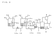
- Fig. 2 shows a major connection relationship of one of the compressors or the compressor 2a, for example, but the same also applies to the other compressor 2b.
- the compressor 2a will be described in the following.
- an initial oil amount A of the compressor 2a is 1.8L (abbreviation for liter. The same applies to the following).
- a critical oil amount B is 0.5L, and the oil regulator 6a has 0.5L at this time.
- An initial oil amount C in the accumulator 5a (the same applies to the accumulator 5b) is 4.5L, and a height D of the oil equalizing pipe 10 is set at the position of 2L. Also, a height E of the oil return hole 8a in the gas intake pipe 7a is at the position of 5.2L, and it is so configured that when coming up to 5.2L or more, the oil is sucked through the oil return hole 8a and returned to the compressor 2a.
- the lowest portion (bottom-face height) of the accumulator 5a is set at the height of the pipeline (the oil return pipe 13a) that connects the accumulator 5a and the oil regulator 6a to each other or higher.
- Table 1 shows an example of a result of examination on a remaining amount of the stored oil of an accumulator (Acc) when control time (operation time interval) and a compressor driving frequency are changed in simulation of the oil equalizing operation.
- Acc accumulator
- 6 minutes per 120 minutes means that the oil equalizing operation is successively performed for 6 minutes after 120 minutes of the usual operation.
- the frequency of "110/35”, for example, means that the compressor is operated at the frequency of 110 Hz during the usual operation and at 35 Hz during the oil equalizing operation.
- the control time and the compressor operation frequency can be acquired from Table 1 so that the oil amount 4.5L to the minimum of 1 L can be ensured all the time in the accumulator 5a.
- Table 2 shows a result of the remaining amount in the accumulator 5a when the oil equalizing pipe position (position of the end inflow port) of the accumulator 5a is changed from 1 L to 4L under a condition of the control time of 6 minutes per 120 minutes.
- Table 2 shows it is optimal that the position of the end inflow port position of the oil equalizing pipe 10 is the position of 2L.
- the remaining amount in the accumulator 5a becomes 0 in other cases when the end inflow port positions of the oil equalizing pipe 10 are 1 L, 3L, and 4L. Since the optimal end inflow port position of the oil equalizing pipe 10 is determined also by the capacity of the accumulator, a conclusion cannot be readily made, but under the condition that at least 1 L is ensured all the time, the position at the height of 40 to 60% of the capacity of the accumulator is considered to be favorable.
- Table 3 shows an example of the driving frequency of each outdoor machine during the oil equalizing operation when three outdoor machines 1 a, 1b, and 1c are connected in parallel as shown in Fig. 3 , for example.
- Fig. 3 since the constituent components of the outdoor machine 1 c are the same as those of the outdoor machines 1 a and 1b, reference characters c or b are attached to the numerals in order indicating each constituent component.
- the flows of the refrigerant and the refrigerating oil are the same as in Fig. 1 .
- the oil equalizing operation after 1 hour is performed with the No. 1 outdoor machine 1 a and the No. 2 outdoor machine 1b at the frequency of 90 Hz and the No. 3 outdoor machine 1c at the frequency of 45 Hz
- the oil equalizing operation after 2 hours is performed with the No. 1 outdoor machine 1a and the No. 3 outdoor machine 1c at the frequency of 90 Hz and the No. 2 outdoor machine 1 b at the frequency of 45 Hz
- the oil equalizing operation after 3 hours is performed with the No. 2 outdoor machine 1 b and the No. 3 outdoor machine 1c at the frequency of 90 Hz and the No. 1 outdoor machine 1a at the frequency of 45 Hz.
- the mode returns to the initial mode, and the oil equalizing operation is performed with the frequencies same to those in the first hour.
- the controller 30 controls the oil amount of the compressor to an appropriate oil amount while it is ensured that the minimum oil amount is in the accumulator all the time. As a result, breakage of the compressor caused by oil depletion can be avoided, and highly reliable operation of the refrigerating device 100 can be performed.
- the same effect can be obtained as long as the refrigerant and the refrigerator oil are a compatible combination. Therefore, similar effects can be obtained even if HFC refrigerants or a mixture of such refrigerants, HC refrigerants and a mixture of such refrigerants or natural refrigerants such as CO 2 , water and the like are used as a refrigerant, and oil compatible with them such as ester oil in the case of the HFC refrigerants, mineral oil in the case of the HC refrigerants, PAG oil in the case of CO 2 and the like are used as oil.
Landscapes
- Engineering & Computer Science (AREA)
- Physics & Mathematics (AREA)
- Mechanical Engineering (AREA)
- Thermal Sciences (AREA)
- General Engineering & Computer Science (AREA)
- Compression-Type Refrigeration Machines With Reversible Cycles (AREA)
- Air Conditioning Control Device (AREA)
- Compressor (AREA)
Abstract
Description
- The present invention relates to a refrigerating device provided with a multiple outdoor machine that uses a plurality of outdoor machine units in combination and particularly to a configuration of an oil circuit that prevents uneven distribution of refrigerator oil among the outdoor machine units constituting the multiple outdoor machine and operation control thereof.
- Methods of appropriately supplying oil (refrigerator oil) to a plurality of compressors include use of a refrigerating device described in Japanese Patent No.
3937884 - On the other hand, in the refrigerator, it is demanded to increase in refrigerating capacity, and it has been considered to increase in capacity by combining a plurality of existing refrigerators in order to realize to increase in capacity easily and inexpensively.
- As means for satisfying the above demand, as in illustrated in Japanese Patent No.
3930654 -
- Patent Literature 1: Japanese Patent No.
3937884 Fig. 1 ) - Patent Literature 2: Japanese Patent No.
3930654 Fig. 1 ) - When the configuration of a large-capacity refrigerator is to be used in a form in which a plurality of outdoor units are connected in parallel, if they are simply connected with each other, oil distribution becomes uneven, which causes a problem that oil is gradually decreased in an outdoor unit in which an oil distribution amount is less, the oil soon becomes depleted and the compressor of the corresponding outdoor unit is broken. To cope with this problem, as illustrated in
Patent Literature 1, if an accumulator, which is the only oil storage portion, is connected to a plurality of compressors and the accumulators of the respective outdoor machines are unified, the accumulator cannot be used in common with the conventional outdoor machines which are used singularly. Though a method in communication of the oil storage portions installed on the high pressure side of each outdoor machine each other is also disclosed inPatent Literature 2, if the oil storage portion is installed on the low pressure side, a driving force to fluidize the oil is decreased, and equalizing of the oil is difficult, which is a problem. - In consideration of the above conventional problems, the present invention aims to provide a refrigerating device that improves reliability of a refrigerator operation by avoiding oil depletion of a specific outdoor unit and by operating so as to equalize and supply oil to all the compressors when a large-capacity refrigerator provided with an oil storage portion on the low pressure side is constructed and that can be realized inexpensively by combining existing refrigerators.
- A refrigerating device of the present invention is a refrigerating device that forms a refrigerating cycle in which a plurality of outdoor machines, each provided at least with a compressor, a condenser and an accumulator, and an indoor machine provided with decompressing means and an evaporator are connected in parallel by piping, having an oil return pipe that returns refrigerator oil stored in said accumulator to said compressor, an oil equalizing pipe that connects the accumulators to each other, and a controller that controls an operation of said compressor and on/off of an electromagnetic valve deposed on said oil equalizing pipe.
- In the present invention, since the oil return pipes that return the refrigerator oil stored in the accumulators to the compressor, the oil equalizing pipe that connects the accumulators to each other, and the controller that controls the operation of the compressor and the on/off of the electromagnetic valve deposed on the oil equalizing pipe are provided, the refrigerator oil can be equalized and supplied to the compressors of all the outdoor machines, and oil depletion of the compressor can be prevented. Also, the refrigerating device can be inexpensively realized by combining conventional refrigerators.
-
- [
Fig. 1] Fig. 1 is a refrigerant circuit diagram of a refrigeratingdevice illustrating Embodiment 1 of the present invention. - [
Fig. 2] Fig. 2 is a circuit diagram illustrating a connection relationship between an accumulator and a compressor, which are essential parts of the present invention. - [
Fig. 3] Fig. 3 is a refrigerant circuit diagram of a refrigeratingdevice illustrating Embodiment 2 of the present invention. - Embodiments of a refrigerating device according to the present invention will be described below by referring to the attached drawings.
-
Fig. 1 is a refrigerant circuit diagram of a refrigerating device 100 according toEmbodiment 1 of the present invention.
The refrigerating device 100 ofEmbodiment 1 is provided with a plurality of (two in this example) outdoor machines (also referred to as outdoor units) 1a and 1b, and the outdoor machines 1 a and 1 b are connected in parallel with a indoor machine (also referred to as indoor units) 20, which is usually plural, having an expansion valve 21 that is decompressing means and anevaporator 22 by means of aliquid pipeline 23 and agas pipeline 24. The outdoor machines 1a and 1b are provided with compressors 2a and 2b, oil separators 3a and 3b, condensers 4a and 4b, accumulators 5a and 5b, and oil regulators 6a and 6b, respectively. By connecting the condensers 4a and 4b to theliquid pipeline 23 leading to the expansion valve 21 and by connecting the accumulators 5a and 5b to thegas pipeline 24 from theevaporator 22 via a distributor 25a, a refrigerating cycle is formed through which a refrigerant and the refrigerator oil contained in the refrigerant circulate. - The accumulators 5a and 5b are connected to each other by an
oil equalizing pipe 10 in order to prevent uneven distribution of oil amounts stored in the individual accumulator. In theoil equalizing pipe 10, an electromagnetic valve 12a that opens/closes communication of the oil is provided. Here, end portions 10a and 10b of the equalizingpipe 10 penetrate through and are inserted into the bottom portions of the accumulators 5a and 5b, respectively, and end inlet of theoil equalizing pipe 10 is installed at a predetermined height from (the same height as) the bottom face of each of the accumulators 5a and 5b. As a result, a minimum oil amount that surely stores in the accumulators 5a and 5b all the time can be set. Also, a gas refrigerant (including refrigerator oil that could not be separated) in the accumulators 5a and 5b is sucked into the compressors 2a and 2b via gas intake pipes 7a and 7b. The gas intake pipes 7a and 7b have one ends, which are to be inserted into the accumulators 5a and 5b, formed in the U-shape, and the U-shaped pipe portions have oil return holes 8a and 8b, respectively. Moreover, oil return pipes 13a and 13b that return the oil stored in the accumulators 5a and 5b to the compressors 2a and 2b have one ends that penetrate through and connect to the bottom portion of the accumulators 5a and 5b, while the other ends are connected to the oil regulators 6a and 6b. - The oil regulators 6a and 6b and the compressors 2a and 2b are connected by oil intake pipes 14a and 14b and pressure equalizing pipes 15a and 15b respectively. Inside the oil regulators 6a and 6b, float valves (not shown) interlocking with floats are provided. If the oil level is not more than the specified height, the float valve is opened, and the oil is supplied to the compressors 2a and 2b. If the oil level reaches the specified height, the float valve is shut off so that oil supply to the compressors 2a and 2b is stopped. The oil separated by the oil separators 3a and 3b and stored is returned to the compressors 2a and 2b via the gas intake pipes 7a and 7b through capillary tubes, not shown, or directly without passing through the capillary tubes.
Reference numeral 30 denotes a controller that controls operations of the compressors 2a and 2b and opening/closing of the electromagnetic valve 12a provided in theoil equalizing pipe 10. - The compressors 2a and 2b are inverter-type compressors of a low-pressure shell type, in which the inside of a shell such as a scroll is at a low pressure, and has a structure in which the refrigerator oil is held in the compressor shell. Also, in this refrigerating device 100, a required oil amount is an amount obtained by totaling the appropriate oil amount in the compressors 2a and 2b and the oil amount present in each part of the refrigerating device 100, and as an oil amount to be filled, an oil amount larger than this oil amount is filled in advance. The extra oil is stored in the accumulators 5a and 5b. In the oil stored in the compressors 2a and 2b, an amount of oil taken out from the compressor rapidly increases to the oil level or more, and a compression load is increased. Thus, the appropriate oil amounts in the compressors 2a and 2b become an oil level corresponding to a sufficient oil amount at which the amount of oil taken out does not rapidly increase and the oil does not become depleted. Also, a refrigerant and a refrigerator oil that are soluble with each other are used. For example, in case that the refrigerant is R22, mineral oil is used as the refrigerator oil, and in case that the refrigerant is R404A or R410A, ester oil is used as the refrigerator oil.
- Subsequently, a flow of the refrigerant in the refrigerating device 100 in
Embodiment 1 will be described. The flow of the refrigerant is shown by a solid-line arrow inFig. 1 .
A high-temperature high-pressure gas refrigerant discharged from the compressors 2a and 2b is condensed and liquefied by the condensers 4a and 4b via the oil separators 3a and 3b and then, is decompressed by the expansion valve 21 of theindoor machine 20 via theliquid pipeline 23 and turns into a two-phase refrigerant, is evaporated and gasified by theevaporator 22 and then, enters into the accumulators 5a and 5b of each of the outdoor machines 1 a and 1 b via thegas pipeline 24 and the distributor 25a and moreover, the evaporated and gasified refrigerant is sucked into the compressors 2a and 2b via the gas intake pipes 7a and 7b, forms a circulating refigerating cycle so that the refrigerant and refrigerator oil circulates. - Subsequently, a flow of the refrigerator oil in the refrigerating device 100 in
Embodiment 1 will be described. The flow of the refrigerator oil is shown by a broken-line arrow inFig. 1 .
Approximately 90% of the refrigerator oil discharged together with the gas refrigerant from the compressors 2a and 2b is separated at the oil separators 3a and 3b. The separated refrigerator oil enters the gas intake pipes 7a and 7b via the capillary tube (not shown) and the like and is returned to the compressors 2a and 2b. The oil not separated in the oil separators 3a and 3b flows into the accumulators 5a and 5b through the condensers 4a and 4b, theliquid pipeline 23, the expansion valve 21, theevaporator 22, thegas pipeline 24, and the distributor 25a. In the accumulators 5a and 5b, the refrigerator oil and the gas refrigerant are separated from each other, and the separated oil is collected in the bottom portions of the accumulators 5a and 5b. The refrigerator oil collected in the accumulators 5a and 5b is supplied to the compressors 2a and 2b from the oil return pipes 13a and 13b via the oil regulators 6a and 6b. In order to make the oil levels of the oil regulators.6a and 6b equal to those of the compressors 2a and 2b, the pressure equalizing pipes 15a and 15b, though which the gas flows, are connected. The extra oil in the refrigerating device is collected in the accumulators 5a and 5b of a low-pressure part. - In the flow of the refrigerant from the accumulators 5a and 5b to the compressors 2a and 2b, pressure loss caused by frictional loss in the pipeline occurs. The differential pressure of this pressure loss is to be a driving force with which the oil flows from the accumulators 5a and 5b to the compressors 2a and 2b. A difference in the oil level heads generated by a difference between the oil levels in the accumulators 5a and 5b and the oil levels in the compressors 2a and 2b affects the flow of oil. If the oil levels of the accumulators 5a and 5b are higher than the oil levels of the compressors 2a and 2b, oil supply is accelerated, while if they are lower, the oil supply is disturbed.
- The oil not having been separated in the oil separators 3a and 3b circulates through the refrigerant circuit and flows into the outdoor machines 1a and 1b again. However, if there are a plurality of outdoor machines, oil is not evenly distributed in general and amounts of oil to be returned are different among the outdoor machines. If the refrigerating device 100 of the present embodiment is operated for a long hours, stored amounts of excess oil in the accumulators 5a and 5b become different, and the oil in one of the accumulators might become depleted.
If the oil in the accumulator 5a is depleted, for example, the oil in the compressor 2a is also depleted, which causes breakage of the compressor. - A method of equalizing oil in order to avoid compressor breakage caused by oil unevenly distributed among the outdoor machines will be described. The
oil equalizing pipe 10 is connected between the accumulator 5a and the accumulator 5b via the electromagnetic valve 12a. Moreover, inflow port positions (end positions) of the end portions 10a and 10b of theoil equalizing pipe 10 are set at a predetermined height from the bottom face of each of the accumulators 5a and 5b.
During a usual operation of the compressors 2a and 2b, the electromagnetic valve 12a of theoil equalizing pipe 10 is closed, and the compressors are operated with theoil equalizing pipe 10 that connects the accumulators 5a and 5b closed. At this time, if the float valves of the oil regulators 6a and 6b are open, the oil is sucked into the compressor 2a and 2b, and thus, the oil in the accumulators 5a and 5b flows through the oil return pipes 13a and 13b and is returned from the oil regulators 6a and 6b to the compressors 2a and 2b. However, since the oil is not returned evenly to the compressors 2a and 2b, the oil in the accumulators 5a and 5b are unevenly distributed, and it is expected that one of the accumulator might become oil depleted. Thus, in order to avoid breakage of the compressor caused by oil depletion in the accumulator, an oil equalizing operation is performed subsequent to the usual operation of the compressors 2a and 2b. That is, the usual operation of the compressors 2a and 2b is performed for a predetermined time and the oil equalizing operation is performed in order to decrease the uneven distribution of the oil in the accumulators 5a and 5b before the oil is depleted. This oil equalizing operation is performed by thecontroller 30 in as short a time as possible. The compressor does not necessarily have to be stopped during the oil equalizing operation, but it may be performed after the compressor is stopped. The oil equalizing operation method will be described later. - Also, if the float valve of a certain oil regulator is shut off, oil is unevenly distributed in the accumulators 5a and 5b. When oil is unevenly distributed in the outdoor machine 1 a and the oil level in the oil regulator 6a reaches a specified height and the float valve is shut off, for example, the oil in the accumulator 5b is supplied to the compressor 2b via the oil return pipe 13b and the oil regulator 6b, and the oil in the accumulator 5b begins to become depleted. Thus, the oil equalizing operation is performed before the oil is depleted.
- Methods of determining the timing at which to start the oil equalizing operation are (1) a method of determining the timing using an elapsed time of a usual operation; and (2) a method of determining the timing using a total frequency (total of driving frequencies of the compressors) of the compressors 2a and 2b. In both (1) and (2), the oil equalizing operation is started when the elapsed time or the total frequency reaches a set value or more.
Also, the oil equalizing operation might involve control of an oil return mode. The oil return mode is an operation mode in which oil remained outside the outdoor machine system (indoor machines, extension pipelines and the like) is recovered, and the oil is recovered by stopping the compressor related to oil depletion and circulating the refrigerant. - Here, the oil equalizing operation method will be described. During the oil equalizing operation, the electromagnetic valve 12a of the
oil equalizing pipe 10 is opened, and the oil equalizing operation is performed with theoil equalizing pipe 10 that connects the accumulators 5a and 5b to each other opened. As described above, if the oil in the accumulator 5b will become depleted, for example, excess oil in the accumulator 5a flows to the accumulator 5b via theoil equalizing pipe 10, and the oil amounts in the accumulators 5a and 5b are made equal. Therefore, breakage by oil depletion can be avoided. - Also, since the accumulators 5a and 5b are connected to each other only by the
oil equalizing pipe 10 provided with the electromagnetic valve 12a, they can be used in common with the conventional outdoor machines used singularly, and reliable operation of the refrigerating device 100 can be performed. - Also, since the
oil equalizing pipe 10 extends over the outdoor machines 1a and 1 b, its length is longer than that of the oil return pipes 13a and 13b. Thus, the pipeline diameter of theoil equalizing pipe 10 is made to be larger than that of the oil return pipes 13a and 13b, whereby frictional loss in the oil flow of theoil equalizing pipe 10 is reduced. By means of this action, the flow rate of oil flowing through theoil equalizing pipe 10 is increased, and time required for oil equalizing between the accumulators 5a and 5b can be reduced. - Also, the accumulators 5a and 5b are installed at higher positions than the compressors 2a and 2b. If the oil levels of the accumulators 5a and 5b are higher than the compressors 2a and 2b, the flow rate of oil flowing through the
oil equalizing pipe 10 is increased, whereby reduction of the oil equalizing operation time can be promoted. Moreover, since the pipeline diameter of the required oil passage can be made small, an amount of oil required to be filled in the refrigerating device can be reduced. - Subsequently, an oil-amount relationship between the compressors 2a and 2b and the accumulators 5a and 5b, which are essential parts of the present invention, will be described by using
Fig. 2 . Numeric values shown below are only examples and intended for facilitation of understanding.
Fig. 2 shows a major connection relationship of one of the compressors or the compressor 2a, for example, but the same also applies to the other compressor 2b. Unless specified otherwise, the compressor 2a will be described in the following.
First, an initial oil amount A of the compressor 2a is 1.8L (abbreviation for liter. The same applies to the following). A critical oil amount B is 0.5L, and the oil regulator 6a has 0.5L at this time.
An initial oil amount C in the accumulator 5a (the same applies to the accumulator 5b) is 4.5L, and a height D of theoil equalizing pipe 10 is set at the position of 2L. Also, a height E of the oil return hole 8a in the gas intake pipe 7a is at the position of 5.2L, and it is so configured that when coming up to 5.2L or more, the oil is sucked through the oil return hole 8a and returned to the compressor 2a. The lowest portion (bottom-face height) of the accumulator 5a is set at the height of the pipeline (the oil return pipe 13a) that connects the accumulator 5a and the oil regulator 6a to each other or higher. - Table 1 shows an example of a result of examination on a remaining amount of the stored oil of an accumulator (Acc) when control time (operation time interval) and a compressor driving frequency are changed in simulation of the oil equalizing operation. In the simulation, conditions under which oil in the outdoor machine 1a is depleted most easily are set, for example.
-
[Table 1] Control time Frequency (Hz) Acc remaining amount (L) Rated as 6 minutes per 120 minutes 110/35 1 Good 80/30 0 Bad 60/0 0 Bad 3 minutes per 60 minutes 110/35 1 Good 90/45 1 Good - In Table 1, "6 minutes per 120 minutes", for example, means that the oil equalizing operation is successively performed for 6 minutes after 120 minutes of the usual operation. The frequency of "110/35", for example, means that the compressor is operated at the frequency of 110 Hz during the usual operation and at 35 Hz during the oil equalizing operation.
The control time and the compressor operation frequency can be acquired from Table 1 so that the oil amount 4.5L to the minimum of 1 L can be ensured all the time in the accumulator 5a. - Table 2 shows a result of the remaining amount in the accumulator 5a when the oil equalizing pipe position (position of the end inflow port) of the accumulator 5a is changed from 1 L to 4L under a condition of the control time of 6 minutes per 120 minutes.
-
[Table 2] Control time Acc oil equalizing pipe position (L) Acc remaining amount (L) Rated as 6 minutes per 120 minutes 1.0 0 Bad 2.0 1 Good 3.0 0 Bad 4.0 0 Bad - Table 2 shows it is optimal that the position of the end inflow port position of the
oil equalizing pipe 10 is the position of 2L. The remaining amount in the accumulator 5a becomes 0 in other cases when the end inflow port positions of theoil equalizing pipe 10 are 1 L, 3L, and 4L. Since the optimal end inflow port position of theoil equalizing pipe 10 is determined also by the capacity of the accumulator, a conclusion cannot be readily made, but under the condition that at least 1 L is ensured all the time, the position at the height of 40 to 60% of the capacity of the accumulator is considered to be favorable. - Table 3 shows an example of the driving frequency of each outdoor machine during the oil equalizing operation when three outdoor machines 1 a, 1b, and 1c are connected in parallel as shown in
Fig. 3 , for example. InFig. 3 , since the constituent components of the outdoor machine 1 c are the same as those of the outdoor machines 1 a and 1b, reference characters c or b are attached to the numerals in order indicating each constituent component. The flows of the refrigerant and the refrigerating oil are the same as inFig. 1 . -
[Table 3] Control time Oil equalizing operation driving frequency of outdoor machine No. 1 No. 2 No. 3 1 Hr/3 minutes 90 90 45 2 Hr/3 minutes 90 45 90 3 Hr/3 minutes 45 90 90 - In Table 3, supposing that the usual operation time is 1 hour and the oil equalizing operation time is 3 minutes, for example, the oil equalizing operation after 1 hour is performed with the No. 1 outdoor machine 1 a and the No. 2 outdoor machine 1b at the frequency of 90 Hz and the No. 3 outdoor machine 1c at the frequency of 45 Hz, the oil equalizing operation after 2 hours is performed with the No. 1 outdoor machine 1a and the No. 3 outdoor machine 1c at the frequency of 90 Hz and the No. 2 outdoor machine 1 b at the frequency of 45 Hz, and the oil equalizing operation after 3 hours is performed with the No. 2 outdoor machine 1 b and the No. 3 outdoor machine 1c at the frequency of 90 Hz and the No. 1 outdoor machine 1a at the frequency of 45 Hz. Then, after 4 hours, the mode returns to the initial mode, and the oil equalizing operation is performed with the frequencies same to those in the first hour.
- As described above, while all the electromagnetic valves 12a and 12b are kept open by the
controller 30, by executing control in which a specific compressor is operated at a frequency lower than other compressors and the compressor that performs a low-frequency operation is alternated every predetermined time so that all the compressors are operated at the low frequency at least once, the oil amount of the compressor can be adjusted to an appropriate oil amount while it is ensured that the minimum oil amount is in the accumulator all the time. As a result, breakage of the compressor caused by oil depletion can be avoided, and highly reliable operation of the refrigerating device 100 can be performed. - Also, in the operation of the refrigerating device 100 described in
Embodiment 1, the same effect can be obtained as long as the refrigerant and the refrigerator oil are a compatible combination. Therefore, similar effects can be obtained even if HFC refrigerants or a mixture of such refrigerants, HC refrigerants and a mixture of such refrigerants or natural refrigerants such as CO2, water and the like are used as a refrigerant, and oil compatible with them such as ester oil in the case of the HFC refrigerants, mineral oil in the case of the HC refrigerants, PAG oil in the case of CO2 and the like are used as oil. - 1a, 1b, 1 c outdoor machine, 2a, 2b, 2c compressor, 3a, 3b, 3c oil separator, 4a, 4b, 4c condenser, 5a, 5b, 5c accumulator, 6a, 6b, 6c oil regulator, 7a, 7b, 7c gas intake pipe, 8a, 8b, 8c oil return hole, 10 oil equalizing pipe, 10a, 10b, 10c end portion of oil equalizing pipe, 12a, 12b electromagnetic valve, 13a, 13b, 13c oil return pipe, 14a, 14b, 14c oil intake pipe, 15a, 15b, 15c pressure equalizing pipe, 20 indoor machine, 21 expansion valve, 22 evaporator, 23 liquid pipe, 24 gas pipeline, 25a, 25b distributor, 30 controller, 100 refrigerating device.
Claims (6)
- A refrigerating device that forms a refrigerating cycle in which a plurality of outdoor machines , each provided at least with a compressor, a condenser and an accumulator, and an indoor machine provided with decompressing means and an evaporator are connected in parallel by piping, comprising:an oil return pipe that returns refrigerator oil stored in said accumulator to said compressor ;an oil equalizing pipe that connects the accumulators to each other; anda controller that controls an operation of said compressor and on/off of an electromagnetic valve deposed on said oil equalizing pipe.
- The refrigerating device of claim 1, wherein
an end inflow port of said oil equalizing pipe is deposed at a predetermined height from the bottom face of said accumulator. - The refrigerating device of claim 1 or 2, further comprising:an oil regulator that adjusts an oil amount to be supplied to said compressor and is provided between said accumulator and said compressor; whereinsaid oil return pipe connects said accumulator and said oil regulator.
- The refrigerating device of any one of claims 1 to 3, wherein
a pipeline diameter of said oil equalizing pipe is larger than a pipeline diameter of said oil return pipe. - The refrigerating device of any one of claims 1 to 4, wherein
said accumulator is deposed at a position higher than said compressor so that an oil head difference is generated. - A refrigerating device that forms a refrigerating cycle in which a plurality of outdoor machines each provided at least with a compressor, a condenser and an accumulator, and an indoor machine provided with decompressing means and an evaporator are connected in parallel by piping, comprising:an oil regulator that adjusts an oil amount to be supplied to said compressor and is disposed between said accumulator and said compressor;an oil return pipe that returns refrigerator oil stored in said accumulator to said oil regulator;an oil equalizing pipe that connects said accumulators to each other; anda controller that controls an operation of said compressor and on/off of an electromagnetic valve provided in said oil equalizing pipe, whereinsaid controller executes the operation control in which while all the electromagnetic valves are kept open, a specific compressor is operated at a frequency lower than the other compressors, and the compressor to be operated at the low frequency is alternated every predetermined time so that all the compressors are operated at the low frequency at least once.
Applications Claiming Priority (2)
| Application Number | Priority Date | Filing Date | Title |
|---|---|---|---|
| JP2009086191 | 2009-03-31 | ||
| PCT/JP2010/001742 WO2010113395A1 (en) | 2009-03-31 | 2010-03-11 | Refrigeration device |
Publications (3)
| Publication Number | Publication Date |
|---|---|
| EP2416089A1 true EP2416089A1 (en) | 2012-02-08 |
| EP2416089A4 EP2416089A4 (en) | 2018-03-28 |
| EP2416089B1 EP2416089B1 (en) | 2020-04-22 |
Family
ID=42827714
Family Applications (1)
| Application Number | Title | Priority Date | Filing Date |
|---|---|---|---|
| EP10758181.1A Not-in-force EP2416089B1 (en) | 2009-03-31 | 2010-03-11 | Refrigeration device |
Country Status (5)
| Country | Link |
|---|---|
| US (1) | US9541313B2 (en) |
| EP (1) | EP2416089B1 (en) |
| JP (1) | JP5084950B2 (en) |
| CN (1) | CN102365508B (en) |
| WO (1) | WO2010113395A1 (en) |
Cited By (1)
| Publication number | Priority date | Publication date | Assignee | Title |
|---|---|---|---|---|
| EP3534086A4 (en) * | 2016-10-31 | 2019-09-18 | Mitsubishi Electric Corporation | Refrigeration cycle device |
Families Citing this family (21)
| Publication number | Priority date | Publication date | Assignee | Title |
|---|---|---|---|---|
| JP5975742B2 (en) * | 2012-06-05 | 2016-08-23 | 三菱電機株式会社 | Refrigeration equipment |
| ITTV20120169A1 (en) * | 2012-08-22 | 2014-02-23 | Enex Srl | REFRIGERANT CIRCUIT |
| JP6157182B2 (en) * | 2013-04-03 | 2017-07-05 | 三菱電機株式会社 | Refrigeration equipment |
| CN104390380B (en) * | 2014-10-31 | 2016-01-20 | 南海油脂工业(赤湾)有限公司 | A kind of edible fat production cooling refrigeration system |
| EP3023713A1 (en) * | 2014-11-19 | 2016-05-25 | Danfoss A/S | A method for controlling a vapour compression system with an ejector |
| JP6293647B2 (en) * | 2014-11-21 | 2018-03-14 | ヤンマー株式会社 | heat pump |
| WO2017029011A1 (en) | 2015-08-14 | 2017-02-23 | Danfoss A/S | A vapour compression system with at least two evaporator groups |
| JP6538493B2 (en) * | 2015-09-08 | 2019-07-03 | 三菱重工サーマルシステムズ株式会社 | Cyclone oil separator and refrigeration system |
| CN108139132B (en) | 2015-10-20 | 2020-08-25 | 丹佛斯有限公司 | Method for controlling vapor compression system with variable receiver pressure set point |
| MX374485B (en) | 2015-10-20 | 2025-03-06 | Danfoss As | METHOD FOR CONTROLLING A VAPOR COMPRESSION SYSTEM IN EJECTOR MODE FOR AN EXTENDED TIME. |
| CN105805986A (en) * | 2016-04-27 | 2016-07-27 | 田幼华 | Heat pump system with auxiliary oil return |
| CN109564031A (en) * | 2016-08-04 | 2019-04-02 | 三菱电机株式会社 | Refrigerating plant |
| EP3913299A1 (en) * | 2016-12-21 | 2021-11-24 | Mitsubishi Electric Corporation | Refrigeration cycle apparatus |
| CN108731311B (en) * | 2018-07-12 | 2024-05-10 | 珠海凌达压缩机有限公司 | Compressor assembly and air conditioning system thereof |
| WO2020052234A1 (en) * | 2018-09-11 | 2020-03-19 | 青岛海信日立空调系统有限公司 | Compressor oil return control method and apparatus |
| DK180146B1 (en) | 2018-10-15 | 2020-06-25 | Danfoss As Intellectual Property | Heat exchanger plate with strenghened diagonal area |
| US11460224B2 (en) * | 2018-10-31 | 2022-10-04 | Emerson Climate Technologies, Inc. | Oil control for climate-control system |
| JP7233517B2 (en) * | 2019-02-28 | 2023-03-06 | 三菱電機株式会社 | refrigeration cycle equipment |
| JP6788073B2 (en) * | 2019-06-05 | 2020-11-18 | 三菱重工サーマルシステムズ株式会社 | Cyclone oil separator and refrigeration system |
| CN115406133B (en) * | 2021-05-27 | 2024-05-31 | 上海兴邺材料科技有限公司 | Air conditioning system and control method thereof |
| CN118140103A (en) * | 2021-11-01 | 2024-06-04 | 三菱电机株式会社 | Refrigeration cycle device |
Family Cites Families (34)
| Publication number | Priority date | Publication date | Assignee | Title |
|---|---|---|---|---|
| US3248895A (en) * | 1964-08-21 | 1966-05-03 | William V Mauer | Apparatus for controlling refrigerant pressures in refrigeration and air condition systems |
| JPH01127865A (en) * | 1987-11-13 | 1989-05-19 | Toshiba Corp | Air conditioner |
| US4779427A (en) * | 1988-01-22 | 1988-10-25 | E. Squared Incorporated | Heat actuated heat pump |
| GB2215866B (en) * | 1988-02-09 | 1992-06-24 | Toshiba Kk | Multi-type air conditioner system with oil level control for parallel operated compressor therein |
| US4912937A (en) * | 1988-04-25 | 1990-04-03 | Mitsubishi Denki Kabushiki Kaisha | Air conditioning apparatus |
| JP2708492B2 (en) * | 1988-09-07 | 1998-02-04 | 株式会社日立製作所 | Method for manufacturing semiconductor device |
| US5369958A (en) * | 1992-10-15 | 1994-12-06 | Mitsubishi Denki Kabushiki Kaisha | Air conditioner |
| ZA948879B (en) * | 1993-11-13 | 1996-02-05 | Mintek | A process for controlling a series of flotation cells |
| JPH0972636A (en) * | 1995-07-06 | 1997-03-18 | Mitsubishi Heavy Ind Ltd | Accumulator and air conditioner utilizing this accumulator |
| JPH102626A (en) * | 1996-06-12 | 1998-01-06 | Mitsubishi Heavy Ind Ltd | Air conditioning device |
| JP3413044B2 (en) * | 1997-02-20 | 2003-06-03 | 株式会社日立製作所 | Air conditioner |
| JPH1114200A (en) * | 1997-06-20 | 1999-01-22 | Matsushita Refrig Co Ltd | Accumulator |
| JPH11142002A (en) * | 1997-11-07 | 1999-05-28 | Mitsubishi Electric Corp | Refrigeration air conditioner |
| US5901559A (en) * | 1998-09-09 | 1999-05-11 | Ac&R Components, Inc. | Electromechanical regulator |
| JP3930654B2 (en) * | 1998-11-12 | 2007-06-13 | 三菱電機株式会社 | refrigerator |
| AU2706301A (en) * | 2000-01-21 | 2001-07-31 | Toshiba Carrier Corporation | Oil amount detector, refrigeration apparatus and air conditioner |
| JP4489890B2 (en) * | 2000-01-21 | 2010-06-23 | 東芝キヤリア株式会社 | Multi-type air conditioner |
| JP2001289519A (en) * | 2000-04-06 | 2001-10-19 | Mitsubishi Electric Corp | Refrigeration equipment |
| TWI237682B (en) * | 2000-07-07 | 2005-08-11 | Sanyo Electric Co | Freezing apparatus |
| US6453697B1 (en) * | 2001-04-23 | 2002-09-24 | Designed Metal Products, Inc. | Seal for vessel and method of forming same |
| JP3848098B2 (en) * | 2001-05-01 | 2006-11-22 | 株式会社日立製作所 | Air conditioner |
| JP3937884B2 (en) | 2002-03-22 | 2007-06-27 | 三菱電機株式会社 | Refrigeration air conditioner |
| JP4300804B2 (en) * | 2002-06-11 | 2009-07-22 | ダイキン工業株式会社 | Oil leveling circuit of compression mechanism, heat source unit of refrigeration apparatus, and refrigeration apparatus including the same |
| CN100373112C (en) * | 2003-10-06 | 2008-03-05 | 大金工业株式会社 | Refrigerating device |
| KR100564444B1 (en) * | 2003-10-20 | 2006-03-29 | 엘지전자 주식회사 | Apparatus and method for preventing accumulation of liquid refrigerant in air conditioners |
| KR100556773B1 (en) * | 2003-11-05 | 2006-03-10 | 엘지전자 주식회사 | Oil recovery device and accumulator oil recovery method of accumulator of air conditioner |
| KR100511288B1 (en) * | 2003-11-14 | 2005-08-31 | 엘지전자 주식회사 | Out door unit of air conditioner with four compressors |
| KR100758901B1 (en) * | 2004-11-17 | 2007-09-14 | 엘지전자 주식회사 | Multi air conditioner |
| US7735333B2 (en) * | 2005-07-01 | 2010-06-15 | Ming-Li Tso | Thermal compensation system and device there of in heat pump and refrigeration system |
| JP4816220B2 (en) * | 2006-04-20 | 2011-11-16 | ダイキン工業株式会社 | Refrigeration equipment |
| CN101063567B (en) * | 2006-04-27 | 2011-05-11 | 海尔集团公司 | Multiple air-conditioning unit pipe device |
| CN101093121B (en) * | 2006-06-21 | 2010-05-26 | 海尔集团公司 | A multi-connected air conditioner unit oil balance device |
| MY165544A (en) * | 2006-07-18 | 2018-04-03 | Oyl Res And Development Centre Sdn Bhd | Oil management system for multiple condensers |
| JP4877054B2 (en) * | 2007-04-27 | 2012-02-15 | 株式会社富士通ゼネラル | Rotary compressor |
-
2010
- 2010-03-11 US US13/259,290 patent/US9541313B2/en not_active Expired - Fee Related
- 2010-03-11 JP JP2011506982A patent/JP5084950B2/en not_active Expired - Fee Related
- 2010-03-11 CN CN201080015354.3A patent/CN102365508B/en not_active Expired - Fee Related
- 2010-03-11 EP EP10758181.1A patent/EP2416089B1/en not_active Not-in-force
- 2010-03-11 WO PCT/JP2010/001742 patent/WO2010113395A1/en not_active Ceased
Non-Patent Citations (1)
| Title |
|---|
| See references of WO2010113395A1 * |
Cited By (1)
| Publication number | Priority date | Publication date | Assignee | Title |
|---|---|---|---|---|
| EP3534086A4 (en) * | 2016-10-31 | 2019-09-18 | Mitsubishi Electric Corporation | Refrigeration cycle device |
Also Published As
| Publication number | Publication date |
|---|---|
| CN102365508A (en) | 2012-02-29 |
| JP5084950B2 (en) | 2012-11-28 |
| JPWO2010113395A1 (en) | 2012-10-04 |
| EP2416089A4 (en) | 2018-03-28 |
| US20120006041A1 (en) | 2012-01-12 |
| WO2010113395A1 (en) | 2010-10-07 |
| CN102365508B (en) | 2014-07-09 |
| EP2416089B1 (en) | 2020-04-22 |
| US9541313B2 (en) | 2017-01-10 |
Similar Documents
| Publication | Publication Date | Title |
|---|---|---|
| EP2416089B1 (en) | Refrigeration device | |
| CN107024045B (en) | Condenser evaporator system and method of operating same | |
| KR20150020220A (en) | Refrigeration device | |
| JP2010071614A (en) | Refrigerating device | |
| JP3937884B2 (en) | Refrigeration air conditioner | |
| WO2019173330A1 (en) | Cascade system for use in economizer compressor and related methods | |
| JP5783783B2 (en) | Heat source side unit and refrigeration cycle apparatus | |
| JP5975742B2 (en) | Refrigeration equipment | |
| US20180266737A1 (en) | Air-conditioning apparatus and operation controller of air-conditioning apparatus | |
| WO2015029204A1 (en) | Air conditioner | |
| JP5975706B2 (en) | Accumulator and refrigeration cycle apparatus | |
| JP2006275440A (en) | Refrigeration equipment | |
| JP5225895B2 (en) | Air conditioner | |
| JP3448794B2 (en) | Refrigeration equipment | |
| JP3930654B2 (en) | refrigerator | |
| JP4845945B2 (en) | Refrigeration equipment | |
| JP2011027314A (en) | Air conditioner | |
| JP2003028523A (en) | Refrigeration equipment and oil tank integrated accumulator | |
| JP4278229B2 (en) | Air conditioner | |
| JP2013053757A (en) | Refrigerant circuit system | |
| JP5959373B2 (en) | Refrigeration equipment | |
| JP4476946B2 (en) | Refrigeration equipment | |
| US20060005570A1 (en) | Air conditioner | |
| JP2004301461A (en) | Air conditioner | |
| WO2023073989A1 (en) | Refrigeration cycle apparatus |
Legal Events
| Date | Code | Title | Description |
|---|---|---|---|
| PUAI | Public reference made under article 153(3) epc to a published international application that has entered the european phase |
Free format text: ORIGINAL CODE: 0009012 |
|
| 17P | Request for examination filed |
Effective date: 20110930 |
|
| AK | Designated contracting states |
Kind code of ref document: A1 Designated state(s): AT BE BG CH CY CZ DE DK EE ES FI FR GB GR HR HU IE IS IT LI LT LU LV MC MK MT NL NO PL PT RO SE SI SK SM TR |
|
| DAX | Request for extension of the european patent (deleted) | ||
| RIC1 | Information provided on ipc code assigned before grant |
Ipc: F25B 31/00 20060101AFI20171003BHEP Ipc: F25B 43/02 20060101ALI20171003BHEP |
|
| RA4 | Supplementary search report drawn up and despatched (corrected) |
Effective date: 20180228 |
|
| RIC1 | Information provided on ipc code assigned before grant |
Ipc: F25B 43/02 20060101ALI20180222BHEP Ipc: F25B 31/00 20060101AFI20180222BHEP |
|
| STAA | Information on the status of an ep patent application or granted ep patent |
Free format text: STATUS: EXAMINATION IS IN PROGRESS |
|
| 17Q | First examination report despatched |
Effective date: 20190701 |
|
| REG | Reference to a national code |
Ref country code: DE Ref legal event code: R079 Ref document number: 602010064014 Country of ref document: DE Free format text: PREVIOUS MAIN CLASS: F25B0001000000 Ipc: F25B0031000000 |
|
| GRAP | Despatch of communication of intention to grant a patent |
Free format text: ORIGINAL CODE: EPIDOSNIGR1 |
|
| STAA | Information on the status of an ep patent application or granted ep patent |
Free format text: STATUS: GRANT OF PATENT IS INTENDED |
|
| RIC1 | Information provided on ipc code assigned before grant |
Ipc: F25B 43/00 20060101ALN20190925BHEP Ipc: F25B 31/00 20060101AFI20190925BHEP Ipc: F25B 43/02 20060101ALI20190925BHEP |
|
| INTG | Intention to grant announced |
Effective date: 20191023 |
|
| GRAS | Grant fee paid |
Free format text: ORIGINAL CODE: EPIDOSNIGR3 |
|
| GRAA | (expected) grant |
Free format text: ORIGINAL CODE: 0009210 |
|
| STAA | Information on the status of an ep patent application or granted ep patent |
Free format text: STATUS: THE PATENT HAS BEEN GRANTED |
|
| AK | Designated contracting states |
Kind code of ref document: B1 Designated state(s): AT BE BG CH CY CZ DE DK EE ES FI FR GB GR HR HU IE IS IT LI LT LU LV MC MK MT NL NO PL PT RO SE SI SK SM TR |
|
| REG | Reference to a national code |
Ref country code: GB Ref legal event code: FG4D |
|
| REG | Reference to a national code |
Ref country code: CH Ref legal event code: EP |
|
| REG | Reference to a national code |
Ref country code: IE Ref legal event code: FG4D |
|
| REG | Reference to a national code |
Ref country code: DE Ref legal event code: R096 Ref document number: 602010064014 Country of ref document: DE |
|
| REG | Reference to a national code |
Ref country code: AT Ref legal event code: REF Ref document number: 1260656 Country of ref document: AT Kind code of ref document: T Effective date: 20200515 |
|
| REG | Reference to a national code |
Ref country code: LT Ref legal event code: MG4D |
|
| REG | Reference to a national code |
Ref country code: NL Ref legal event code: MP Effective date: 20200422 |
|
| PG25 | Lapsed in a contracting state [announced via postgrant information from national office to epo] |
Ref country code: SE Free format text: LAPSE BECAUSE OF FAILURE TO SUBMIT A TRANSLATION OF THE DESCRIPTION OR TO PAY THE FEE WITHIN THE PRESCRIBED TIME-LIMIT Effective date: 20200422 Ref country code: LT Free format text: LAPSE BECAUSE OF FAILURE TO SUBMIT A TRANSLATION OF THE DESCRIPTION OR TO PAY THE FEE WITHIN THE PRESCRIBED TIME-LIMIT Effective date: 20200422 Ref country code: PT Free format text: LAPSE BECAUSE OF FAILURE TO SUBMIT A TRANSLATION OF THE DESCRIPTION OR TO PAY THE FEE WITHIN THE PRESCRIBED TIME-LIMIT Effective date: 20200824 Ref country code: NL Free format text: LAPSE BECAUSE OF FAILURE TO SUBMIT A TRANSLATION OF THE DESCRIPTION OR TO PAY THE FEE WITHIN THE PRESCRIBED TIME-LIMIT Effective date: 20200422 Ref country code: NO Free format text: LAPSE BECAUSE OF FAILURE TO SUBMIT A TRANSLATION OF THE DESCRIPTION OR TO PAY THE FEE WITHIN THE PRESCRIBED TIME-LIMIT Effective date: 20200722 Ref country code: GR Free format text: LAPSE BECAUSE OF FAILURE TO SUBMIT A TRANSLATION OF THE DESCRIPTION OR TO PAY THE FEE WITHIN THE PRESCRIBED TIME-LIMIT Effective date: 20200723 Ref country code: IS Free format text: LAPSE BECAUSE OF FAILURE TO SUBMIT A TRANSLATION OF THE DESCRIPTION OR TO PAY THE FEE WITHIN THE PRESCRIBED TIME-LIMIT Effective date: 20200822 Ref country code: FI Free format text: LAPSE BECAUSE OF FAILURE TO SUBMIT A TRANSLATION OF THE DESCRIPTION OR TO PAY THE FEE WITHIN THE PRESCRIBED TIME-LIMIT Effective date: 20200422 |
|
| REG | Reference to a national code |
Ref country code: AT Ref legal event code: MK05 Ref document number: 1260656 Country of ref document: AT Kind code of ref document: T Effective date: 20200422 |
|
| PG25 | Lapsed in a contracting state [announced via postgrant information from national office to epo] |
Ref country code: LV Free format text: LAPSE BECAUSE OF FAILURE TO SUBMIT A TRANSLATION OF THE DESCRIPTION OR TO PAY THE FEE WITHIN THE PRESCRIBED TIME-LIMIT Effective date: 20200422 Ref country code: HR Free format text: LAPSE BECAUSE OF FAILURE TO SUBMIT A TRANSLATION OF THE DESCRIPTION OR TO PAY THE FEE WITHIN THE PRESCRIBED TIME-LIMIT Effective date: 20200422 Ref country code: BG Free format text: LAPSE BECAUSE OF FAILURE TO SUBMIT A TRANSLATION OF THE DESCRIPTION OR TO PAY THE FEE WITHIN THE PRESCRIBED TIME-LIMIT Effective date: 20200722 |
|
| REG | Reference to a national code |
Ref country code: DE Ref legal event code: R097 Ref document number: 602010064014 Country of ref document: DE |
|
| PG25 | Lapsed in a contracting state [announced via postgrant information from national office to epo] |
Ref country code: IT Free format text: LAPSE BECAUSE OF FAILURE TO SUBMIT A TRANSLATION OF THE DESCRIPTION OR TO PAY THE FEE WITHIN THE PRESCRIBED TIME-LIMIT Effective date: 20200422 Ref country code: RO Free format text: LAPSE BECAUSE OF FAILURE TO SUBMIT A TRANSLATION OF THE DESCRIPTION OR TO PAY THE FEE WITHIN THE PRESCRIBED TIME-LIMIT Effective date: 20200422 Ref country code: CZ Free format text: LAPSE BECAUSE OF FAILURE TO SUBMIT A TRANSLATION OF THE DESCRIPTION OR TO PAY THE FEE WITHIN THE PRESCRIBED TIME-LIMIT Effective date: 20200422 Ref country code: AT Free format text: LAPSE BECAUSE OF FAILURE TO SUBMIT A TRANSLATION OF THE DESCRIPTION OR TO PAY THE FEE WITHIN THE PRESCRIBED TIME-LIMIT Effective date: 20200422 Ref country code: DK Free format text: LAPSE BECAUSE OF FAILURE TO SUBMIT A TRANSLATION OF THE DESCRIPTION OR TO PAY THE FEE WITHIN THE PRESCRIBED TIME-LIMIT Effective date: 20200422 Ref country code: ES Free format text: LAPSE BECAUSE OF FAILURE TO SUBMIT A TRANSLATION OF THE DESCRIPTION OR TO PAY THE FEE WITHIN THE PRESCRIBED TIME-LIMIT Effective date: 20200422 Ref country code: SM Free format text: LAPSE BECAUSE OF FAILURE TO SUBMIT A TRANSLATION OF THE DESCRIPTION OR TO PAY THE FEE WITHIN THE PRESCRIBED TIME-LIMIT Effective date: 20200422 Ref country code: EE Free format text: LAPSE BECAUSE OF FAILURE TO SUBMIT A TRANSLATION OF THE DESCRIPTION OR TO PAY THE FEE WITHIN THE PRESCRIBED TIME-LIMIT Effective date: 20200422 |
|
| PG25 | Lapsed in a contracting state [announced via postgrant information from national office to epo] |
Ref country code: PL Free format text: LAPSE BECAUSE OF FAILURE TO SUBMIT A TRANSLATION OF THE DESCRIPTION OR TO PAY THE FEE WITHIN THE PRESCRIBED TIME-LIMIT Effective date: 20200422 Ref country code: SK Free format text: LAPSE BECAUSE OF FAILURE TO SUBMIT A TRANSLATION OF THE DESCRIPTION OR TO PAY THE FEE WITHIN THE PRESCRIBED TIME-LIMIT Effective date: 20200422 |
|
| PLBE | No opposition filed within time limit |
Free format text: ORIGINAL CODE: 0009261 |
|
| STAA | Information on the status of an ep patent application or granted ep patent |
Free format text: STATUS: NO OPPOSITION FILED WITHIN TIME LIMIT |
|
| 26N | No opposition filed |
Effective date: 20210125 |
|
| PG25 | Lapsed in a contracting state [announced via postgrant information from national office to epo] |
Ref country code: SI Free format text: LAPSE BECAUSE OF FAILURE TO SUBMIT A TRANSLATION OF THE DESCRIPTION OR TO PAY THE FEE WITHIN THE PRESCRIBED TIME-LIMIT Effective date: 20200422 |
|
| PG25 | Lapsed in a contracting state [announced via postgrant information from national office to epo] |
Ref country code: MC Free format text: LAPSE BECAUSE OF FAILURE TO SUBMIT A TRANSLATION OF THE DESCRIPTION OR TO PAY THE FEE WITHIN THE PRESCRIBED TIME-LIMIT Effective date: 20200422 |
|
| REG | Reference to a national code |
Ref country code: CH Ref legal event code: PL |
|
| REG | Reference to a national code |
Ref country code: BE Ref legal event code: MM Effective date: 20210331 |
|
| PG25 | Lapsed in a contracting state [announced via postgrant information from national office to epo] |
Ref country code: CH Free format text: LAPSE BECAUSE OF NON-PAYMENT OF DUE FEES Effective date: 20210331 Ref country code: LU Free format text: LAPSE BECAUSE OF NON-PAYMENT OF DUE FEES Effective date: 20210311 Ref country code: LI Free format text: LAPSE BECAUSE OF NON-PAYMENT OF DUE FEES Effective date: 20210331 Ref country code: FR Free format text: LAPSE BECAUSE OF NON-PAYMENT OF DUE FEES Effective date: 20210331 Ref country code: IE Free format text: LAPSE BECAUSE OF NON-PAYMENT OF DUE FEES Effective date: 20210311 |
|
| PG25 | Lapsed in a contracting state [announced via postgrant information from national office to epo] |
Ref country code: BE Free format text: LAPSE BECAUSE OF NON-PAYMENT OF DUE FEES Effective date: 20210331 |
|
| REG | Reference to a national code |
Ref country code: DE Ref legal event code: R084 Ref document number: 602010064014 Country of ref document: DE |
|
| REG | Reference to a national code |
Ref country code: GB Ref legal event code: 746 Effective date: 20230113 |
|
| PG25 | Lapsed in a contracting state [announced via postgrant information from national office to epo] |
Ref country code: HU Free format text: LAPSE BECAUSE OF FAILURE TO SUBMIT A TRANSLATION OF THE DESCRIPTION OR TO PAY THE FEE WITHIN THE PRESCRIBED TIME-LIMIT; INVALID AB INITIO Effective date: 20100311 Ref country code: CY Free format text: LAPSE BECAUSE OF FAILURE TO SUBMIT A TRANSLATION OF THE DESCRIPTION OR TO PAY THE FEE WITHIN THE PRESCRIBED TIME-LIMIT Effective date: 20200422 |
|
| P01 | Opt-out of the competence of the unified patent court (upc) registered |
Effective date: 20230512 |
|
| PG25 | Lapsed in a contracting state [announced via postgrant information from national office to epo] |
Ref country code: MK Free format text: LAPSE BECAUSE OF FAILURE TO SUBMIT A TRANSLATION OF THE DESCRIPTION OR TO PAY THE FEE WITHIN THE PRESCRIBED TIME-LIMIT Effective date: 20200422 |
|
| PGFP | Annual fee paid to national office [announced via postgrant information from national office to epo] |
Ref country code: DE Payment date: 20240130 Year of fee payment: 15 Ref country code: GB Payment date: 20240201 Year of fee payment: 15 |
|
| PG25 | Lapsed in a contracting state [announced via postgrant information from national office to epo] |
Ref country code: TR Free format text: LAPSE BECAUSE OF FAILURE TO SUBMIT A TRANSLATION OF THE DESCRIPTION OR TO PAY THE FEE WITHIN THE PRESCRIBED TIME-LIMIT Effective date: 20200422 |
|
| PG25 | Lapsed in a contracting state [announced via postgrant information from national office to epo] |
Ref country code: MT Free format text: LAPSE BECAUSE OF FAILURE TO SUBMIT A TRANSLATION OF THE DESCRIPTION OR TO PAY THE FEE WITHIN THE PRESCRIBED TIME-LIMIT Effective date: 20200422 |
|
| REG | Reference to a national code |
Ref country code: DE Ref legal event code: R119 Ref document number: 602010064014 Country of ref document: DE |
|
| GBPC | Gb: european patent ceased through non-payment of renewal fee |
Effective date: 20250311 |
|
| PG25 | Lapsed in a contracting state [announced via postgrant information from national office to epo] |
Ref country code: DE Free format text: LAPSE BECAUSE OF NON-PAYMENT OF DUE FEES Effective date: 20251001 |
|
| PG25 | Lapsed in a contracting state [announced via postgrant information from national office to epo] |
Ref country code: GB Free format text: LAPSE BECAUSE OF NON-PAYMENT OF DUE FEES Effective date: 20250311 |