JP5975706B2 - Accumulator and refrigeration cycle apparatus - Google Patents
Accumulator and refrigeration cycle apparatus Download PDFInfo
- Publication number
- JP5975706B2 JP5975706B2 JP2012090715A JP2012090715A JP5975706B2 JP 5975706 B2 JP5975706 B2 JP 5975706B2 JP 2012090715 A JP2012090715 A JP 2012090715A JP 2012090715 A JP2012090715 A JP 2012090715A JP 5975706 B2 JP5975706 B2 JP 5975706B2
- Authority
- JP
- Japan
- Prior art keywords
- refrigerant
- oil
- liquid
- accumulator
- compressor
- Prior art date
- Legal status (The legal status is an assumption and is not a legal conclusion. Google has not performed a legal analysis and makes no representation as to the accuracy of the status listed.)
- Active
Links
Images


Description
本発明は冷凍サイクル装置に用いるアキュムレータ等に関するものである。 The present invention relates to an accumulator used in a refrigeration cycle apparatus.
例えば、並列に接続された複数の圧縮機、凝縮器、膨張弁、蒸発器、アキュムレータを順次接続して冷媒回路を構成する冷凍サイクル装置がある。冷凍サイクル装置においては、例えば圧縮機における圧縮機構の駆動を円滑に行う等するために冷凍機油を用いている。冷凍機油は冷媒と共に冷媒回路を循環する。 For example, there is a refrigeration cycle apparatus in which a refrigerant circuit is configured by sequentially connecting a plurality of compressors, condensers, expansion valves, evaporators, and accumulators connected in parallel. In the refrigeration cycle apparatus, for example, refrigeration oil is used to smoothly drive the compression mechanism in the compressor. The refrigerating machine oil circulates in the refrigerant circuit together with the refrigerant.
ここで、冷媒回路に流れる冷媒において、液状の冷媒(液冷媒)が多くなって圧縮機吸入側(低圧側)に戻る液バックが発生する。このとき、圧縮機に流入する冷媒が冷凍機油に比べて多くなるため冷凍機油の濃度が低下する。冷凍機油の濃度が低下すると、圧縮機構の破損等につながるため、液バック時においても複数台の圧縮機における冷凍機油の濃度を確保できるようにした冷凍装置(冷凍サイクル装置)がある(例えば、特許文献1参照)。 Here, in the refrigerant flowing through the refrigerant circuit, a liquid back that returns to the compressor suction side (low pressure side) occurs due to an increase in liquid refrigerant (liquid refrigerant). At this time, since the refrigerant flowing into the compressor increases as compared with the refrigerating machine oil, the concentration of the refrigerating machine oil decreases. When the concentration of the refrigerating machine oil is reduced, the compression mechanism is damaged. Therefore, there is a refrigerating apparatus (refrigeration cycle apparatus) that can ensure the concentration of refrigerating machine oil in a plurality of compressors even during liquid back (for example, Patent Document 1).
このような冷凍装置では、冷凍機油は冷媒と相溶なものを用い、圧縮機内の余剰の冷凍機油をアキュムレータに回収する油回収部を設け、アキュムレータに冷凍機油を保持しておく。そして、例えば膨張弁の不良など冷媒回路の異常により多量の液バックが発生し、液冷媒でアキュムレータがオーバーフローした場合においても、複数台の圧縮機にはアキュムレータ内の油と冷媒が混合したものが供給される。したがって、複数台の圧縮機にはある一定の油濃度を持った液冷媒が流入することになるので、液バック状態が連続して発生しても圧縮機の油濃度をある一定値以上に保つことができる。 In such a refrigerating apparatus, the refrigerating machine oil is compatible with the refrigerant, and an oil recovery unit that recovers excess refrigerating machine oil in the compressor is provided in the accumulator, and the refrigerating machine oil is held in the accumulator. Even when a large amount of liquid back occurs due to abnormality in the refrigerant circuit, such as a defective expansion valve, and the accumulator overflows with liquid refrigerant, a plurality of compressors are a mixture of oil and refrigerant in the accumulator. Supplied. Accordingly, liquid refrigerant having a certain oil concentration flows into a plurality of compressors, so that the oil concentration in the compressor is kept above a certain value even if a liquid back state continuously occurs. be able to.
また、例えば2台以上の圧縮機を有している場合、低湿り度、低周波数等の低冷媒循環量で冷媒を循環させたときの液バック時に、一方の圧縮機へ偏ることを低減させるため、アキュムレータのU字管(冷媒流出配管)の最下部に液戻し穴を設けている。そして、低湿り度、低周波数等により低冷媒循環量で液バックした場合、液面をU字管(冷媒流出配管)吸入口まで上昇させないようにし(U字管吸入口から液が戻らないようにし)、液戻し穴のみから戻すようにしている。例えば液戻し穴がない場合、U字管(冷媒流出配管)吸入口の高さに差があると、その際によって、液バックする圧縮機に偏りが生じる。ここで、液戻し穴があっても液戻し穴の高さが異なることで液バックが偏ってしまうことも考えられるが、液戻し穴がない場合よりもさらに低循環量の液バックの場合にしか起こらない。また、偏りによって生じる圧縮機間に生じる冷凍機油の濃度の差は、圧縮機の発熱により油濃度が十分に確保できる程度である。 In addition, for example, when two or more compressors are provided, it is possible to reduce the bias toward one of the compressors during liquid back when the refrigerant is circulated with a low refrigerant circulation amount such as low humidity and low frequency. Therefore, a liquid return hole is provided in the lowermost part of the U-shaped tube (refrigerant outflow piping) of the accumulator. And when the liquid is backed up with a low refrigerant circulation rate due to low wetness, low frequency, etc., the liquid level should not be raised to the U-shaped pipe (refrigerant outlet pipe) inlet (the liquid will not return from the U-shaped pipe inlet) In other words, the liquid is returned only from the liquid return hole. For example, when there is no liquid return hole and there is a difference in the height of the U-shaped pipe (refrigerant outflow pipe) suction port, the liquid backed compressor is biased depending on the height. Here, even if there is a liquid return hole, it is possible that the liquid back will be biased due to the difference in the height of the liquid return hole, but in the case of a liquid back with a lower circulation rate than when there is no liquid return hole Only happens. Moreover, the difference in the concentration of the refrigeration oil produced between the compressors caused by the bias is such that the oil concentration can be sufficiently secured by the heat generated by the compressor.
通常、アキュムレータに保持された冷凍機油は、アキュムレータの底部から接続された油戻し配管により圧縮機の適正な高さ位置の外側外郭に連通して設置されたオイルレギュレータを介して圧縮機へ給油される。オイルレギュレータはフロートと、フロートに連動する弁とで構成されて、フロートが圧縮機の適正油量位置を検知し、圧縮機内の油量を制御する。それぞれの圧縮機において油量が適正油量より増加するとフロートが上昇し、それに応じて弁が閉じて給油が停止される。逆にそれぞれの圧縮機において油量が適正油量より減少するとフロートが下降し、それに応じて弁が開いて油戻し配管からの給油が開始される。アキュムレータの液戻し穴はU字管最下部側面に設置され、万が一油戻し配管が詰まり、アキュムレータの冷凍機油面が上昇した場合でも、応急的にU字管の液戻し穴から各圧縮機に冷凍機油を返油できるようにしている。 Usually, the refrigeration oil held in the accumulator is supplied to the compressor via an oil regulator installed in communication with the outer shell at an appropriate height of the compressor by an oil return pipe connected from the bottom of the accumulator. The The oil regulator is composed of a float and a valve linked to the float, and the float detects the proper oil amount position of the compressor and controls the oil amount in the compressor. When the oil amount increases from the appropriate oil amount in each compressor, the float rises, and the valve closes accordingly and the oil supply is stopped. On the contrary, when the oil amount is decreased from the appropriate oil amount in each compressor, the float is lowered, and the valve is opened accordingly, and the oil supply from the oil return pipe is started. The liquid return hole of the accumulator is installed on the bottom side of the U-shaped pipe. Even if the oil return pipe is clogged and the oil level of the accumulator refrigeration machine rises, it is frozen as soon as possible from the liquid return hole of the U-shaped pipe to each compressor. The machine oil can be returned.
しかし、上記のような従来の冷凍サイクル装置には以下のような問題があった。例えば、上記の冷凍装置においては、冷媒と冷凍機油を相溶の組合せとしていたが、非相溶、弱相溶の組み合わせの場合、アキュムレータ内は、上層が冷凍機油リッチ層(以下、油リッチ層という)、下層が冷媒リッチ層の二層に分かれる。U字管(冷媒流出配管)の液戻し穴のみから冷媒リッチ層の液冷媒等が戻ることになるため、低油濃度の液冷媒等が圧縮機に戻ることになる。このため、圧縮機の信頼性が低下してしまう可能性があった。 However, the conventional refrigeration cycle apparatus as described above has the following problems. For example, in the above refrigerating apparatus, the refrigerant and the refrigerating machine oil are in a compatible combination. However, in the case of a non-compatible and weakly compatible combination, in the accumulator, the upper layer is a refrigerating machine oil rich layer (hereinafter referred to as an oil rich layer). The lower layer is divided into two layers, a refrigerant rich layer. Since the liquid refrigerant in the refrigerant rich layer returns only from the liquid return hole of the U-shaped pipe (refrigerant outflow pipe), the liquid refrigerant having a low oil concentration returns to the compressor. For this reason, the reliability of the compressor may be lowered.
また、アキュムレータ内の冷凍機油面とU字管最下部の液戻し穴との距離が近くなるため、冷媒流量が多くなり油面が乱れると、液バック状態でなくても液戻し穴を介して圧縮機に冷凍機油が流入して、圧縮機が過給油状態となる。この場合、油温上昇によるモータ損傷、油圧縮等によって圧縮機スクロール部を破損してしまう等、圧縮機の信頼性が低下してしまう可能性があった。 In addition, since the distance between the refrigerator oil level in the accumulator and the liquid return hole at the bottom of the U-shaped pipe is reduced, if the flow rate of refrigerant increases and the oil level is disturbed, the liquid level will not pass through the liquid return hole even if it is not in the liquid back state. Refrigerator oil flows into the compressor, and the compressor enters a supercharged state. In this case, there has been a possibility that the reliability of the compressor may be lowered, for example, the compressor scroll portion may be damaged due to motor damage due to oil temperature rise or oil compression.
本発明は、上記のような課題を解決するためになされたもので、冷媒と共に適量の冷凍機油が圧縮機に戻るようなアキュムレータ等を得ることを目的とする。 The present invention has been made to solve the above-described problems, and an object thereof is to obtain an accumulator or the like in which an appropriate amount of refrigerating machine oil returns to the compressor together with the refrigerant.
本発明に係るアキュムレータは、冷凍サイクル装置の蒸発器と圧縮機の冷媒吸入側との間に設置するアキュムレータにおいて、液体状の冷媒及び冷媒と非相溶性又は難溶性を有する冷凍機油を保有する、密閉した容器と、蒸発器からの冷凍機油を含む冷媒を容器内に流入させる流入配管と、容器内の冷凍機油を含む液体状の冷媒を配管内に流入させるための液戻し穴及び容器内において液戻し穴よりも高い位置にあり、管内に気体状又は液体状の冷媒を流入させるための吸入口を有し、圧縮機に冷媒を流出させる複数の流出配管とを備え、液戻し穴の位置の容器内における高さは、容器内における吸入口の高さから、容器内に充填される冷凍機油量分に係る高さ分を引いた高さ以上である。 The accumulator according to the present invention, in an accumulator installed between the evaporator of the refrigeration cycle apparatus and the refrigerant suction side of the compressor, holds liquid refrigerant and refrigerating machine oil that is incompatible or hardly soluble with the refrigerant. In a sealed container, an inflow pipe for allowing the refrigerant containing the refrigerating machine oil from the evaporator to flow into the container, a liquid return hole for letting the liquid refrigerant containing the refrigerating machine oil in the container flow into the pipe, and the container A position that is higher than the liquid return hole, has a suction port for allowing a gaseous or liquid refrigerant to flow into the pipe, and has a plurality of outflow pipes for allowing the refrigerant to flow out to the compressor. The height in the container is equal to or higher than the height of the suction port in the container minus the height related to the amount of refrigerating machine oil filled in the container.
本発明のアキュムレータによれば、流出配管が有する液戻し穴の容器内における高さを、容器内における吸入口の高さから、容器内に保有する冷凍機油量分に係る高さ分を引いた以上の高さに位置するようにしたので、湿り度に関わらず、液バックが発生したときでも、油濃度の高い液状の冷媒を圧縮機に戻すことができ、かつ圧縮機への過給油を防止し、信頼性を高めることができるという効果が得られる。 According to the accumulator of the present invention, the height of the liquid return hole of the outflow pipe in the container is subtracted from the height of the suction port in the container by the height related to the amount of refrigerating machine oil held in the container. Since it is located at the above height, liquid refrigerant with a high oil concentration can be returned to the compressor even when a liquid back occurs regardless of the wetness, and supercharging to the compressor can be performed. The effect that it can prevent and can improve reliability is acquired.
実施の形態1.
図1は本発明の実施の形態に係る冷凍サイクル装置の構成を示す図である。ここでは冷凍サイクル装置の例として、対象空間、対象物等を冷却する冷凍装置について説明する。図1に係る冷凍装置は、圧縮機2a、2b、油分離器3a、3b、凝縮器4、受液器5、膨張弁6、蒸発器7及びアキュムレータ1を順次環状に配管接続して冷媒回路を構成している。圧縮機2a及び油分離器3aと圧縮機2b及び油分離器3bとは冷媒回路において並列に配管接続している。ここで、添字で区別等している複数の同種の機器等について、特に区別したり、特定したりする必要がない場合には、添字を省略して記載する場合もある。また、温度、圧力等の高低については、特に絶対的な値との関係で高低等が定まっているものではなく、システム、装置等における状態、動作等において相対的に定まるものとする。
FIG. 1 is a diagram showing a configuration of a refrigeration cycle apparatus according to an embodiment of the present invention. Here, as an example of the refrigeration cycle apparatus, a refrigeration apparatus that cools a target space, an object, and the like will be described. 1 is a refrigerant circuit in which
アキュムレータ1は、圧縮機2の冷媒吸入側において、例えば圧縮機2に液体の冷媒(液冷媒)等が流れ込まないように液冷媒等を溜めておく容器等を有する。また、本実施の形態では、冷媒(液冷媒及び気体状の冷媒(ガス冷媒))から冷凍機油を分離する(以下、特に区別しない場合は、冷媒と冷凍機油の混合物を冷媒として記載する場合もある)。アキュムレータ1については、後に詳細に説明する。
The
圧縮機2(2a、2b)はそれぞれ冷媒を吸入して圧縮し、高温・高圧のガス状態にして吐出する。本実施の形態の圧縮機2はスクロール等のシェル内部が低圧となる低圧シェルタイプの圧縮機であり、圧縮機シェル内に冷凍機油を保持する構造となっているものとする。ここで、冷凍装置において必要となる冷凍機油の量は、2台の圧縮機2内において適量となる油量だけでなく、冷媒回路を流れる冷凍機油の量を合算した量となる。そこで、冷凍機油は合算した量よりも余裕をもって冷媒回路内に充填しておくものとする。また、ここでは、冷凍機油として、冷媒と非相溶、弱相溶な油を用いるものとする。ただ、例えば、ある温度以上では相溶となり、ある温度未満では非相溶、弱相溶となる冷凍機油等を用いるようにしてもよい。そして、液体の場合、冷凍機油の方が冷媒と比べて比重が軽いものとする。
Each of the compressors 2 (2a, 2b) sucks and compresses the refrigerant, and discharges it in a gas state of high temperature and high pressure. The
油分離器3(3a、3b)は、それぞれ圧縮機2の吐出側に配管接続しており、吐出した冷媒から冷凍機油を分離する。凝縮器4は、例えば室外等の空気(以下、外気という)と冷媒との間で熱交換を行い、冷媒を凝縮液化させる熱交換器である。受液器5は例えば凝縮器4と蒸発器7との間の冷媒調整をするために液冷媒を溜めておくものである。流量調整手段(絞り装置)となる膨張弁6は、冷媒の流量を調整し、減圧して膨張させるものである。蒸発器7は、例えば冷却対象と冷媒との間で熱交換を行い、冷媒を蒸発ガス化させ、冷却対象を冷却する熱交換器である。
The oil separators 3 (3a, 3b) are connected to the discharge side of the
また、吸入配管9(9a、9b)は、それぞれアキュムレータ1と圧縮機2の吸入側とを接続する配管である。そして、返油配管10(10a、10b)は油分離器3が分離した冷凍機油をそれぞれ吸入配管9に流すための配管である。油戻し配管13(13a、13b)はアキュムレータ1の底部と接続されており、圧縮機2に供給(給油)するためのアキュムレータ1内に溜まった冷凍機油が通る配管である。油戻し配管13を通過した冷凍機油は、圧縮機2の外側の外殻に連通して設置されたオイルレギュレータ8を介して圧縮機2に給油される。オイルレギュレータ8(8a、8b)は例えばフロートとフロートに連動する弁とで構成しており、フロートが圧縮機2の油量位置に基づいて弁を開閉し、圧縮機2の油量を制御する。圧縮機2内の冷凍機油の量が適正油量より増加すると、フロートの位置が上昇して弁が閉となり、油戻し配管13からの給油を停止する。逆に圧縮機2内の冷凍機油の量が適正油量より減少するとフロートの位置が下降して弁が開となり油戻し配管13を介して圧縮機2内に給油が行われる。
The suction pipes 9 (9a, 9b) are pipes that connect the
実施の形態1の冷凍サイクル装置における冷媒の流れについて説明する。圧縮機2a、2bは、それぞれ冷媒を吸入し、圧縮して高温・高圧のガス状態にして吐出する。吐出した冷媒は、油分離器3a、3bを通過して凝縮器4へ流入する。凝縮器4は、送風機(図示せず)から供給される外気と冷媒との間で熱交換を行い、冷媒を凝縮液化させる。凝縮液化した冷媒は膨張弁6を通過する。膨張弁6は、通過する凝縮液化した冷媒を減圧する。減圧した冷媒は蒸発器7に流入する。蒸発器7は、冷却対象との熱交換により冷媒を蒸発ガス化する。そして、アキュムレータ1を通過した蒸発ガス化した冷媒は吸入配管9a、9bに分岐する。分岐した冷媒は、それぞれ圧縮機2a、2bが吸入し、吐出する。
The flow of the refrigerant in the refrigeration cycle apparatus of
次に実施の形態1の冷凍サイクル装置における冷凍機油の流れについて説明する。上述したように、圧縮機2a、2bはそれぞれガス冷媒を吐出するが、吐出したガス冷媒には冷凍機油が含まれる。圧縮機2a、2bがガス冷媒と共に吐出した冷凍機油のうち、90%程度を油分離器3a、3bがそれぞれ分離する。油分離器3a、3bが冷媒から分離した冷凍機油は、それぞれ返油配管10a、10bを通って吸入配管9a、9bに流れ、吸入配管9a、9bを介して圧縮機2a、2bに返油される。
Next, the flow of refrigeration oil in the refrigeration cycle apparatus of
一方、油分離器3a、3bが分離できなかった冷凍機油は凝縮器4、受液器5、膨張弁6、蒸発器7を介してアキュムレータ1に流入する。アキュムレータ1は冷凍機油とガス冷媒とを分離する。分離された油はアキュムレータ1の底部に滞留する。アキュムレータ1に滞留する冷凍機油は、油戻し配管13a、13b及びオイルレギュレータ8a、8bを介して圧縮機2a、2bに供給される。
On the other hand, the refrigerating machine oil that cannot be separated by the oil separators 3 a and 3 b flows into the
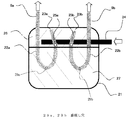
図2は本発明の実施の形態1に係るアキュムレータ1の構造を説明するための図である。図2はアキュムレータ1の断面図を示している。図2において、容器本体21はアキュムレータ1となる密閉容器の本体である。液体が溜まる底部に油戻し配管13が接続されている。流入配管24は、蒸発器7から流出した冷媒を容器本体21に流入させる配管である。この流入配管24において、容器本体21外に出ている管の一部は、容器本体21内の管の最高部分よりも高い位置にある。これにより、液バックした状態で、アキュムレータ1が図2に示すような満液状態で停止した場合に、アキュムレータ1の上流側(圧縮機2の接続とは逆側)に油リッチ層26が移動してアキュムレータ1内からの冷凍機油減少を防ぐことができる。ここで、冷凍装置の運転により、容器本体21に冷媒と冷凍機油との混合物が流入した場合には、図2に示すように混合物は2層に分かれる。2層のうち、上層が冷凍機油が多く含まれる(冷凍機油の濃度が高い)油リッチ層26となり、下層が冷媒リッチ層27となる。
FIG. 2 is a view for explaining the structure of the
U字管(冷媒流出配管)22(22a、22b)の一端は容器本体21を貫通して吸入配管9と接続され、他端は容器本体21内において開口して吸入口23となっている。このため、吸入口23は容器本体21内において高い位置にあり、例えば通常時、冷媒の湿り度が少ない場合等においては、吸入口23からガス冷媒が吸入され、吸入配管9に導く。また、U字管22は液戻し穴25を有している。液戻し穴25は、例えば容器本体21内に溜まった液体(混合物)を吸入配管9に導くための穴である。
One end of the U-shaped pipe (refrigerant outflow pipe) 22 (22a, 22b) passes through the container
本実施の形態のアキュムレータ1においては、液戻し穴25の容器本体21における位置に関し、高さについてはU字管22の吸入口23との関係に基づいて決めるようにしている。ここでは、吸入口23の高さから、容器本体21に保持する冷凍機油の量に対応する分低くした高さ以上の高さに位置するようにする。例えば、容器本体21に24lの液体が流入したときの液面の高さが、容器本体21における吸入口23の高さの位置であるものとする。
In the
ここで、前述したように、冷媒回路内の冷凍機油は、圧縮機2a及び2b内の冷凍機油量と冷凍装置各部に存在する油量とを合算した量よりも余裕をもって充填しており、容器本体21に保持している。例えば、保持に係る冷凍油量が8lである場合は、吸入口23の高さに対し、8lの液体高さ分低い、16lの液体が流入したときの液面の高さを、容器本体21における液戻し穴25の高さに関する位置とする。
Here, as described above, the refrigerating machine oil in the refrigerant circuit is filled with a margin more than the sum of the refrigerating machine oil amount in the
ただ、液体は、液戻し穴25における液ヘッド圧力と、吸入口23から液戻し穴25までのU字管22内における圧損との圧力差で吸込まれる。このため、液戻し穴25の位置が高すぎて、吸入口23と液戻し穴25とにおける高さの差が少なくなると、液戻し穴25の圧損の方が大きくなり、液体が液戻し穴25から吸込まれにくくなり、液戻し穴25を設けた意味がなくなってしまう。そこで、U字管22の吸入口23の高さから余分な冷凍機油の量に対応する分低くした高さ以上で、圧力等を考慮した位置に液戻し穴25を設けることが望ましい。例えば、次式(1)の関係となるように、U字管22の吸入口23と液戻し穴25の高さの差を設定するようにする。
液戻し穴25の圧損<吸入口23と液戻し穴25との高さのヘッド差による圧力
+吸入口23から液戻し穴25までのU字管22内の圧力差
…(1)
However, the liquid is sucked by the pressure difference between the liquid head pressure in the
Pressure loss of
+ Pressure difference in the U-shaped tube 22 from the suction port 23 to the
... (1)
さらに、液戻し穴25の大きさについては、具体的には、例えば湿り度大の液バック(液バック量大)では吸入口23から液が戻るようにし、湿り度小の液バック(液バック量小)では液戻し穴25から戻るような大きさにする。このとき、湿り度大の場合は吸入口23から、また、湿り度小の場合は液戻し穴25から冷凍油リッチな液体が吸入配管9に導かれ、圧縮機2に戻る。
Further, with respect to the size of the
次に本実施の形態におけるアキュムレータ1内の冷凍機油等の流れ等について説明する。ここでは、前述したように、冷媒と冷凍機油とが弱相溶の組み合わせであるものとする。また、低湿り度液バック時に、冷凍機油と液冷媒との混合液がU字管22の吸入口23からではなく、液戻し穴25のみから戻るような場合を想定する。
Next, the flow of the refrigerating machine oil and the like in the
前述したように、アキュムレータ1内に冷凍機油を保有しているため、アキュムレータ1の容器本体21内において、上層は油リッチ層26、下層が冷媒リッチ層27となる。そして、図2に示すように、液戻し穴25よりも低い位置に油リッチ層26と冷媒リッチ層27との境界が形成される。
As described above, since the refrigerating machine oil is held in the
よって、吸入口23の高さから油保有量分低い位置以上に設置した液戻し穴25から油リッチ層26の混合液が圧縮機2に戻る。このため、従来よりも高油濃度の混合液が圧縮機2に戻り、低湿り度液バック時における圧縮機2の油濃度は従来よりも上昇する。例えば、低湿り度液バック時におけるアキュムレータ1内において、相溶油の混合液では油濃度が25%が均一状態にある。一方、冷媒と冷凍機油が弱相溶の組み合わせの混合液では、油リッチ層26の油濃度が40%、冷媒リッチ層27の油濃度が10%となる。このため、油濃度が40%の混合液が返液されることになる。また、湿り度が高い液バック時の場合でも、U字管22の吸入口23から油リッチ層26が圧縮機2に戻る。
Therefore, the liquid mixture of the oil
また、例えば油戻し配管13が詰まる等して、アキュムレータ1内の冷凍機油の油面が上昇することがある。この場合は油戻し配管13の径を太くして配管を詰まりにくくすることで対応する。さらに、通常運転時におけるアキュムレータ1内の冷凍機油面とU字管22の液戻し穴25との距離を保てるため、冷媒流量が多くなり、油面が乱れた場合でも、液戻し穴25が高い位置にあることで、液戻し穴25から冷凍機油が吸い込まれやすくなることを防ぎ、圧縮機2に戻る冷凍機油量を調整して圧縮機2が過給油状態となることを防止できる。
Further, the oil level of the refrigerating machine oil in the
以上のように、実施の形態1の冷凍サイクル装置のアキュムレータ1によれば、冷媒回路において、並列に配管接続した複数の圧縮機の液バック量を例えば均等にするために、U字管22a、22bに設ける液戻し穴25a、25bについて、容器本体21内における高さに係る位置を、吸入口23の高さから、容器本体21に保持する冷凍機油の量に対応する分低くした高さ以上の高さとするようにしたので、低湿り度、高湿り度に関わらず、液バックが発生したときに、油濃度の高い油リッチ層26の液体が吸入配管9に導かれ、圧縮機2に戻る。このため、液バック時の冷凍機油濃度低下による圧縮機2不具合を低減することができ、圧縮機2、冷凍サイクル装置の信頼性を高めることができる。また、このとき、過給油による圧縮機2の油温上昇によるモータ損傷、油圧縮などによる圧縮機スクロール部等の破損を防止することができ、信頼性を高めることができる。
As described above, according to the
実施の形態2.
図3は本発明の実施の形態2に係るアキュムレータ1の構造を説明するための図である。本実施の形態のアキュムレータ1においては、図3に示すように、冷凍機油を戻すための油戻し穴29(29a、29b)を各U字管22の下部側面に設けている。ここで、容器本体21内に溜まる液体の量が増え、油戻し穴29が冷媒リッチ層27に浸かったときに、油戻し穴29から冷媒リッチ層27の液体が圧縮機2に戻る量を減らすために、油戻し穴29の径は液戻し穴25の径より小さいものとする。例えば、液戻し穴25をφ3.0とし、油戻し穴29をφ1.0とする。冷凍機油を戻す量は液バック時に返液する量よりも少なくてよいため、油戻し穴29は液戻し穴25よりも小さい径にすることができる。
FIG. 3 is a view for explaining the structure of the
そして、圧縮機2内の冷凍機油が減少し、アキュムレータ1内の冷凍機油が増加した場合に、吸入配管9を介して冷凍機油を戻すことができるようにすることで、油戻し配管13を接続しなくてもよいため、本実施の形態においては、アキュムレータ1(容器本体21)の底部に油戻し配管13を接続していない。
Then, when the refrigerating machine oil in the
以上のように、実施の形態2の冷凍サイクル装置におけるアキュムレータ1によれば、液戻し穴25(25a、25b)に加え、油戻し穴29(29a、29b)を各U字管22の下部側面に設けるようにしたので、油戻し配管13を配管するよりも、U字管22に油戻し穴29を形成する方が安価に製造等でき、コストダウンをはかることができる。また、配管に係るスペースを省略し、設計、設置等の簡略化をはかることができる。また、油戻し穴29の径が液戻し穴25より小さい径としているので、容器本体21内に溜まる液体の量が増え、冷媒リッチ層27の液体が油戻し穴29を覆ったときに、油戻し穴29から冷媒リッチ層27の液体が油戻し穴29が冷媒リッチ層27に浸かった場合でも、冷媒リッチ層からの液バックを減らし、油濃度低下による圧縮機2の不具合等を低減することができる。また、このとき、過給油による圧縮機2の油温上昇によるモータ損傷、油圧縮などによる圧縮機スクロール部等の破損を防止することができ、信頼性を高めることができる。
As described above, according to the
実施の形態3.
図4は本発明の実施の形態3に係るアキュムレータ1の構造を説明するための図である。本実施の形態のアキュムレータ1においては、図4に示すように、油戻し穴29をU字管22の下部側面に設けると共にアキュムレータ1(容器本体21)の底部に油戻し配管13を接続している。
Embodiment 3 FIG.
FIG. 4 is a view for explaining the structure of the
例えば、実際に設置する装置において、蒸発器7とアキュムレータ1との間の配管長、蒸発器7の容積等に関して変動が大きい場合、アキュムレータ1が有する冷凍機油量も変動する場合がある。この場合、圧縮機2内における冷凍機油量が減少したとしても蒸発器7とアキュムレータ1との間の配管長、蒸発器7容積に冷凍機油が滞留し、アキュムレータ1内油量は増加しないことも想定される。
For example, in a device that is actually installed, when the fluctuation of the pipe length between the
そこで、本実施の形態の冷凍サイクル装置においては、容器本体21内の冷凍機油について、通常は、油戻し配管13、オイルレギュレータ8を介して冷凍機油を戻すようにする。そして、例えば油戻し配管13が詰まる等して、アキュムレータ1内の冷凍機油の油面が上昇したときには、応急的に油戻し穴29から吸入配管9を介して冷凍機油を戻すことができるようにする。このとき、液戻し穴25の位置等を決定するアキュムレータ1保有油量は、想定される蒸発器7とアキュムレータ1との間の配管長が最長となり、蒸発器7の容量が最大となる場合に対し、冷凍機油が滞留することを想定して充?する。
Therefore, in the refrigeration cycle apparatus of the present embodiment, the refrigeration oil in the container
以上のように、実施の形態3の冷凍サイクル装置におけるアキュムレータ1によれば、U字管22の油戻し穴29と油戻し配管13とを両方有しているため、低湿り度の場合、高湿り度の場合とも、液バック時に従来よりも油濃度の高い液冷媒が圧縮機に戻るため液バック時の油濃度低下による圧縮機不具合を低減できる。また、圧縮機2に対し、油戻し穴29から冷凍機油を戻すことができるため、油戻し配管13が詰まった場合にも圧縮機2が油枯渇等で故障することを防止することができる。また、このとき、過給油による圧縮機2の油温上昇によるモータ損傷、油圧縮などによる圧縮機スクロール部等の破損を防止することができ、信頼性を高めることができる。
As described above, according to the
上述した実施の形態では、冷凍装置への適用について説明した。本発明は、これらの装置に限定することなく、例えばヒートポンプ装置等、冷媒回路を構成する他の冷凍サイクル装置にも適用することができる。 In the above-described embodiment, the application to the refrigeration apparatus has been described. The present invention is not limited to these devices, and can also be applied to other refrigeration cycle devices that constitute a refrigerant circuit, such as a heat pump device.
1 アキュムレータ、2,2a,2b 圧縮機、3,3a,3b 油分離器、4 凝縮器、5 受液器、6 膨張弁、7 蒸発器、8,8a,8b オイルレギュレータ、9,9a,9b 吸入配管、10,10a,10b 返油配管、13,13a,13b 油戻し配管、21 容器本体、22,22a,22b U字管、23,23a,23b 吸入口、24 流入配管、25,25a,25b 液戻し穴、26 油リッチ層、27 冷媒リッチ層、29,29a,29b 油戻し穴。 1 accumulator, 2, 2a, 2b compressor, 3, 3a, 3b oil separator, 4 condenser, 5 receiver, 6 expansion valve, 7 evaporator, 8, 8a, 8b oil regulator, 9, 9a, 9b Suction piping, 10, 10a, 10b Oil return piping, 13, 13a, 13b Oil return piping, 21 Container body, 22, 22a, 22b U-shaped tube, 23, 23a, 23b Suction port, 24 Inflow piping, 25, 25a, 25b Liquid return hole, 26 Oil rich layer, 27 Refrigerant rich layer, 29, 29a, 29b Oil return hole.
Claims (5)
液体状の冷媒及び該冷媒と非相溶性又は難溶性を有する冷凍機油を保有する、密閉した容器と、
前記蒸発器からの前記冷凍機油を含む前記冷媒を前記容器内に流入させる流入配管と、
前記容器内の前記冷凍機油を含む前記液体状の冷媒を配管内に流入させるための液戻し穴及び前記容器内において前記液戻し穴よりも高い位置にあり、前記管内に気体状又は液体状の冷媒を流入させるための吸入口を有し、前記圧縮機に前記冷媒を流出させる複数の流出配管とを備え、
前記液戻し穴の位置の前記容器内における高さは、前記容器内における前記吸入口の高さから、前記容器内に充填される冷凍機油量分に係る高さ分を引いた高さ以上であることを特徴とするアキュムレータ。 In the accumulator installed between the evaporator of the refrigeration cycle apparatus and the refrigerant suction side of the compressor,
A sealed container containing a liquid refrigerant and refrigerating machine oil that is incompatible or hardly soluble with the refrigerant;
An inflow pipe through which the refrigerant containing the refrigerating machine oil from the evaporator flows into the container;
A liquid return hole for allowing the liquid refrigerant containing the refrigerating machine oil in the container to flow into the pipe and a position higher than the liquid return hole in the container, and a gas or liquid state in the pipe A suction port for allowing refrigerant to flow in, and a plurality of outlet pipes for allowing the compressor to flow out of the refrigerant;
The height of the position of the liquid return hole in the container is equal to or higher than the height of the suction port in the container minus the height related to the amount of refrigerating machine oil filled in the container. An accumulator characterized by being.
該蒸発器と前記圧縮機の冷媒吸入側との間に設置される請求項1〜請求項3のいずれか一項に記載のアキュムレータと
を配管接続して前記冷媒を循環させる冷媒回路を構成する冷凍サイクル装置。 A plurality of compressors for compressing the sucked refrigerant, a condenser for condensing the refrigerant by heat exchange, a flow rate adjusting means for depressurizing the condensed refrigerant, and evaporating the decompressed refrigerant by heat exchange An evaporator,
The refrigerant circuit which circulates the said refrigerant | coolant by pipe-connecting the accumulator as described in any one of Claims 1-3 installed between this evaporator and the refrigerant | coolant suction side of the said compressor is comprised. Refrigeration cycle equipment.
Priority Applications (1)
| Application Number | Priority Date | Filing Date | Title |
|---|---|---|---|
| JP2012090715A JP5975706B2 (en) | 2012-04-12 | 2012-04-12 | Accumulator and refrigeration cycle apparatus |
Applications Claiming Priority (1)
| Application Number | Priority Date | Filing Date | Title |
|---|---|---|---|
| JP2012090715A JP5975706B2 (en) | 2012-04-12 | 2012-04-12 | Accumulator and refrigeration cycle apparatus |
Publications (2)
| Publication Number | Publication Date |
|---|---|
| JP2013217623A JP2013217623A (en) | 2013-10-24 |
| JP5975706B2 true JP5975706B2 (en) | 2016-08-23 |
Family
ID=49589913
Family Applications (1)
| Application Number | Title | Priority Date | Filing Date |
|---|---|---|---|
| JP2012090715A Active JP5975706B2 (en) | 2012-04-12 | 2012-04-12 | Accumulator and refrigeration cycle apparatus |
Country Status (1)
| Country | Link |
|---|---|
| JP (1) | JP5975706B2 (en) |
Families Citing this family (3)
| Publication number | Priority date | Publication date | Assignee | Title |
|---|---|---|---|---|
| JPWO2015140878A1 (en) * | 2014-03-17 | 2017-04-06 | 三菱電機株式会社 | Accumulator and refrigeration cycle apparatus |
| CN116067035A (en) * | 2021-11-01 | 2023-05-05 | 广东美的暖通设备有限公司 | Air conditioning system, air conditioning outdoor unit and compressor assembly |
| WO2023084771A1 (en) * | 2021-11-15 | 2023-05-19 | 三菱電機株式会社 | Accumulator and refrigeration cycle device |
Family Cites Families (12)
| Publication number | Priority date | Publication date | Assignee | Title |
|---|---|---|---|---|
| JPS5227407Y2 (en) * | 1971-12-07 | 1977-06-22 | ||
| JPS5512139Y2 (en) * | 1975-01-17 | 1980-03-15 | ||
| JPH0490863U (en) * | 1990-12-20 | 1992-08-07 | ||
| JP3284567B2 (en) * | 1991-10-01 | 2002-05-20 | 松下電器産業株式会社 | accumulator |
| JP3104513B2 (en) * | 1993-12-28 | 2000-10-30 | 三菱電機株式会社 | accumulator |
| JPH10160293A (en) * | 1996-11-29 | 1998-06-19 | Sanyo Electric Co Ltd | Freezer and accumulator |
| JPH1114201A (en) * | 1997-06-20 | 1999-01-22 | Matsushita Refrig Co Ltd | Accumulator |
| JP2000046445A (en) * | 1998-07-28 | 2000-02-18 | Mitsubishi Heavy Ind Ltd | Refrigerating cycle |
| JP2002147902A (en) * | 2000-11-07 | 2002-05-22 | Daikin Ind Ltd | Accumulator |
| JP3812389B2 (en) * | 2001-09-17 | 2006-08-23 | 株式会社デンソー | Refrigeration cycle equipment |
| JP3937884B2 (en) * | 2002-03-22 | 2007-06-27 | 三菱電機株式会社 | Refrigeration air conditioner |
| JP5409318B2 (en) * | 2009-12-15 | 2014-02-05 | 三菱電機株式会社 | HEAT PUMP DEVICE AND HEAT PUMP DEVICE OPERATION METHOD |
-
2012
- 2012-04-12 JP JP2012090715A patent/JP5975706B2/en active Active
Also Published As
| Publication number | Publication date |
|---|---|
| JP2013217623A (en) | 2013-10-24 |
Similar Documents
| Publication | Publication Date | Title |
|---|---|---|
| CN110325803B (en) | Oil management for micro-booster type supermarket refrigeration system | |
| KR100846567B1 (en) | Refrigerating apparatus | |
| CN107024045B (en) | Condenser evaporator system and method of operating same | |
| JP5819000B2 (en) | Refrigeration equipment | |
| JP5323023B2 (en) | Refrigeration equipment | |
| EP2998665B1 (en) | Refrigeration device | |
| JP5484889B2 (en) | Refrigeration equipment | |
| JP6264688B2 (en) | Refrigeration equipment | |
| JP2016056966A (en) | Turbo refrigerator | |
| JP5484890B2 (en) | Refrigeration equipment | |
| CN101135502A (en) | Refrigeration circulation mechanism and air conditioner and refrigeratory using same | |
| JP6179842B2 (en) | Refrigeration apparatus and additional refrigerant amount adjusting apparatus for refrigeration apparatus | |
| JP5975706B2 (en) | Accumulator and refrigeration cycle apparatus | |
| JP5759076B2 (en) | Refrigeration equipment | |
| JP5433158B2 (en) | Refrigeration cycle equipment | |
| JP6388260B2 (en) | Refrigeration equipment | |
| JP2002168535A (en) | Fail safe oil lubrication system of helium compressor supplied with gas containing no oil | |
| JP2013174402A (en) | Refrigerating device | |
| EP2581682A1 (en) | Heat pump water heater using co2 refrigerant | |
| JP5372901B2 (en) | Cooling system for data center | |
| JP5225895B2 (en) | Air conditioner | |
| JP6112388B2 (en) | Refrigeration equipment | |
| JP2013053757A (en) | Refrigerant circuit system | |
| JP5934931B2 (en) | Tank for refrigeration cycle apparatus and refrigeration cycle apparatus including the same | |
| EP2525168B1 (en) | Supercritical steam compression heat pump and hot-water supply unit |
Legal Events
| Date | Code | Title | Description |
|---|---|---|---|
| A621 | Written request for application examination |
Free format text: JAPANESE INTERMEDIATE CODE: A621 Effective date: 20150127 |
|
| A977 | Report on retrieval |
Free format text: JAPANESE INTERMEDIATE CODE: A971007 Effective date: 20151111 |
|
| A131 | Notification of reasons for refusal |
Free format text: JAPANESE INTERMEDIATE CODE: A131 Effective date: 20151201 |
|
| A521 | Request for written amendment filed |
Free format text: JAPANESE INTERMEDIATE CODE: A523 Effective date: 20160126 |
|
| TRDD | Decision of grant or rejection written | ||
| A01 | Written decision to grant a patent or to grant a registration (utility model) |
Free format text: JAPANESE INTERMEDIATE CODE: A01 Effective date: 20160621 |
|
| A61 | First payment of annual fees (during grant procedure) |
Free format text: JAPANESE INTERMEDIATE CODE: A61 Effective date: 20160719 |
|
| R150 | Certificate of patent or registration of utility model |
Ref document number: 5975706 Country of ref document: JP Free format text: JAPANESE INTERMEDIATE CODE: R150 |
|
| R250 | Receipt of annual fees |
Free format text: JAPANESE INTERMEDIATE CODE: R250 |
|
| R250 | Receipt of annual fees |
Free format text: JAPANESE INTERMEDIATE CODE: R250 |
|
| R250 | Receipt of annual fees |
Free format text: JAPANESE INTERMEDIATE CODE: R250 |
|
| R250 | Receipt of annual fees |
Free format text: JAPANESE INTERMEDIATE CODE: R250 |
|
| R250 | Receipt of annual fees |
Free format text: JAPANESE INTERMEDIATE CODE: R250 |