EP2415566A1 - Dispositif de poignée supplémentaire - Google Patents
Dispositif de poignée supplémentaire Download PDFInfo
- Publication number
- EP2415566A1 EP2415566A1 EP11186171A EP11186171A EP2415566A1 EP 2415566 A1 EP2415566 A1 EP 2415566A1 EP 11186171 A EP11186171 A EP 11186171A EP 11186171 A EP11186171 A EP 11186171A EP 2415566 A1 EP2415566 A1 EP 2415566A1
- Authority
- EP
- European Patent Office
- Prior art keywords
- unit
- vibration
- damping
- counter
- handle device
- Prior art date
- Legal status (The legal status is an assumption and is not a legal conclusion. Google has not performed a legal analysis and makes no representation as to the accuracy of the status listed.)
- Withdrawn
Links
Images

Classifications
-
- B—PERFORMING OPERATIONS; TRANSPORTING
- B25—HAND TOOLS; PORTABLE POWER-DRIVEN TOOLS; MANIPULATORS
- B25F—COMBINATION OR MULTI-PURPOSE TOOLS NOT OTHERWISE PROVIDED FOR; DETAILS OR COMPONENTS OF PORTABLE POWER-DRIVEN TOOLS NOT PARTICULARLY RELATED TO THE OPERATIONS PERFORMED AND NOT OTHERWISE PROVIDED FOR
- B25F5/00—Details or components of portable power-driven tools not particularly related to the operations performed and not otherwise provided for
- B25F5/006—Vibration damping means
-
- B—PERFORMING OPERATIONS; TRANSPORTING
- B25—HAND TOOLS; PORTABLE POWER-DRIVEN TOOLS; MANIPULATORS
- B25F—COMBINATION OR MULTI-PURPOSE TOOLS NOT OTHERWISE PROVIDED FOR; DETAILS OR COMPONENTS OF PORTABLE POWER-DRIVEN TOOLS NOT PARTICULARLY RELATED TO THE OPERATIONS PERFORMED AND NOT OTHERWISE PROVIDED FOR
- B25F5/00—Details or components of portable power-driven tools not particularly related to the operations performed and not otherwise provided for
- B25F5/02—Construction of casings, bodies or handles
- B25F5/025—Construction of casings, bodies or handles with torque reaction bars for rotary tools
- B25F5/026—Construction of casings, bodies or handles with torque reaction bars for rotary tools in the form of an auxiliary handle
-
- F—MECHANICAL ENGINEERING; LIGHTING; HEATING; WEAPONS; BLASTING
- F16—ENGINEERING ELEMENTS AND UNITS; GENERAL MEASURES FOR PRODUCING AND MAINTAINING EFFECTIVE FUNCTIONING OF MACHINES OR INSTALLATIONS; THERMAL INSULATION IN GENERAL
- F16F—SPRINGS; SHOCK-ABSORBERS; MEANS FOR DAMPING VIBRATION
- F16F7/00—Vibration-dampers; Shock-absorbers
- F16F7/10—Vibration-dampers; Shock-absorbers using inertia effect
- F16F7/104—Vibration-dampers; Shock-absorbers using inertia effect the inertia member being resiliently mounted
- F16F7/116—Vibration-dampers; Shock-absorbers using inertia effect the inertia member being resiliently mounted on metal springs
-
- F—MECHANICAL ENGINEERING; LIGHTING; HEATING; WEAPONS; BLASTING
- F16—ENGINEERING ELEMENTS AND UNITS; GENERAL MEASURES FOR PRODUCING AND MAINTAINING EFFECTIVE FUNCTIONING OF MACHINES OR INSTALLATIONS; THERMAL INSULATION IN GENERAL
- F16F—SPRINGS; SHOCK-ABSORBERS; MEANS FOR DAMPING VIBRATION
- F16F9/00—Springs, vibration-dampers, shock-absorbers, or similarly-constructed movement-dampers using a fluid or the equivalent as damping medium
- F16F9/32—Details
- F16F9/53—Means for adjusting damping characteristics by varying fluid viscosity, e.g. electromagnetically
- F16F9/535—Magnetorheological [MR] fluid dampers
Definitions
- the invention is based on an auxiliary handle device according to the preamble of claim 1.
- the auxiliary handle device comprises an auxiliary handle and a damping device.
- the damping device has a counter-vibration unit with at least one counter-vibration element.
- the invention relates to an auxiliary handle device, in particular for a hand tool, with an auxiliary handle and a damping device, which has a counter-vibration unit with at least one counter-vibration element.
- the counter-vibration unit has an excitation unit which is provided for an excitation of the counter-vibration element to a counter-vibration.
- an "additional handle” is to be understood as an area and / or a component and / or an element which constitutes an application, in particular a gripping, by a hand or several hands of an operator, for the purpose of guiding a handheld power tool by means of the auxiliary handle device, is provided and in addition to another handle, in particular the main handle, in addition to the hand tool can be attached, wherein the auxiliary handle device is arranged laterally on the hand tool and / or can be assembled and disassembled without tools by an operator on the power tool and / or arranged in a front, near the tool area of the power tool and / or the auxiliary handle is rod-shaped.
- the counter-vibration element is excited by means of the excitation unit to a counter-vibration, which counteracts during operation of a vibration of the power tool.
- the counter-vibration element is preferably formed by an absorber mass element, wherein a "absorber mass element” is to be understood in particular an element which is excited at least within a designated frequency range of an output oscillation to a counter-vibration which at least partially counteracts the output oscillation and thus to a reduction of vibrations contributes.
- auxiliary handle device is basically used in conjunction with all hand tool machines that appear useful to the person skilled in the art, in which, in particular, guidance of hand tool machines by means of the additional handle is made easier for an operator. Due to its damping characteristic, the auxiliary handle device is particularly advantageous in connection with an angle grinder.
- an "axial direction” is to be understood as a direction which preferably extends along a longitudinal extension, in particular a length, of the auxiliary handle device.
- the excitation unit has at least one sensor element which leads to a detection of at least one oscillation characteristic of the handheld power tool is provided.
- a vibration parameter and / or a damping parameter of the countervibration of the countervibration element to an instantaneous vibration behavior of the handheld power tool can be achieved by means of the detected vibration characteristic.
- a particularly accurate sensing of the vibration characteristic of the hand tool, in particular in an area of the auxiliary handle device facing the hand tool, can be achieved if the auxiliary handle device has at least one fastening element which is provided for attachment to the hand tool, wherein the sensor element is arranged on the fastening element.
- the excitation unit has at least one adjustment element which is provided for setting an excitation characteristic for the countervibration element, whereby an effective and in particular at least partially automatic adjustment or adaptation of the excitation characteristic of the countervibration element to a momentary vibration characteristic of the handheld power tool can be achieved.
- the excitation characteristic can be set structurally simply by means of a magnetic force.
- a particularly simple design adjustment of a counter-vibration of the counter-vibration element can be achieved if in addition the counter-vibration element is at least partially formed by a permanent magnet.
- a change of the excitation characteristic can thus be achieved particularly quickly.
- the counter-vibration unit has at least one damping means, which is provided for damping a counter-vibration of the counter-vibration element, whereby an advantageous protection of the counter-vibration element and / or other components of the counter-vibration unit reaches a possible overuse and thus in particular a long life of the counter-vibration element and / or the counter-vibration unit can be achieved.
- This can be achieved in a particularly advantageous manner if the damping means is provided by a spring element, in particular an elastomer and / or particularly advantageously by a spring element Coil spring and / or further, the expert appears to be useful spring elements is formed and / or the damping means is formed by a damping fluid.
- the damping fluid is advantageously formed by a pure liquid, by a suspension and / or further damping fluids that appear appropriate to the person skilled in the art.
- the damping device has at least one rheological damping unit.
- a "rheological damping unit” should be understood in particular to mean a damping unit which has at least one rheological element, which is preferably provided for vibration damping.
- a "rheological element” should be understood to mean, in particular, an element in which, by means of, for example, external forces, such as, in particular, a shearing force, application of an electric field and / or a magnetic field, etc., an immediate change of an internal Structure of the element or a change in an interaction of element particles can be achieved with each other.
- the change in the internal structure of the rheological element preferably causes a change in a flow behavior, in particular a change in viscosity, and thus influences a damping force.
- the action of the external forces can be controlled manually by an operator or particularly advantageously be set at least partially automatically via a control or regulation unit. Due to the erfindunlice configuration, a damping property of the rheological damping unit can be varied particularly quickly and thus an advantageous, adapted to a vibration behavior of the power tool vibration damping can be achieved.
- the rheological damping unit has at least one rheological damping means, whereby particularly quickly and effectively a damping property of the damping means can be influenced or changed.
- the damping property of the rheological damping means can advantageously be parameterized within a characteristic field and thus varied within a wide range in its damping characteristic.
- a change of a damping parameter can take place up to 1000 times per second.
- the rheological damping agent is at least partially of a magnetorheological Damping liquid formed, such as from a suspension, in particular from an oil with polyurethane molecules contained therein.
- a magnetorheological Damping liquid formed, such as from a suspension, in particular from an oil with polyurethane molecules contained therein.
- the rheological damping unit has an adjustment unit which is provided for setting a damping parameter of the rheological damping means, whereby an effective and in particular at least partially automatic adjustment or adaptation of the damping characteristic of the damping unit, in particular the magnetorheological damping fluid, reaches a vibration characteristic can be.
- a particularly rapid adaptation or adjustment of the damping characteristic to a current vibration behavior of the handheld power tool can be achieved if the setting unit has at least one sensor element which is provided for detecting a vibration characteristic of the handheld power tool.
- the damping unit has at least one vibration element, whereby advantageously a vibration-damping vibration movement, in particular a counter-vibration to an output vibration of the power tool, can be achieved.
- a vibration parameter of the vibration element can be achieved structurally by changing a parameter of the rheological damping means.
- the vibration element is at least partially formed integrally with the counter-vibration element, whereby further components, space, assembly costs and costs can be advantageously saved.
- a vibration movement of the counter-vibration element can be advantageously transferred to the vibration element.
- the rheological damping unit has at least one magnetizing element, whereby advantageously a magnetic field can be generated in the rheological damping means.
- a magnetizing element is to be understood in particular as an element which is provided for generating a magnetic field within the magnetorheological damping means. A generation of a preferably uniform magnetic field can be achieved if the magnetizing element is at least partially formed by a magnetic coil.
- FIG. 1 is an illustrated by an angle grinder power tool 12 shown in a view from above.
- the angle grinding machine comprises a housing 68 and a main handle 64 integrated in the housing 68.
- the main handle 64 extends on a side 72 facing away from a tool 70 formed by a cutting disk in the direction of a longitudinal direction 74 of the angle grinder.
- An auxiliary handle device 10 which extends transversely to the longitudinal direction 74 of the angle grinder, is disposed on a front, tool-near region 76 of the angle grinder.
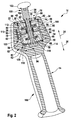
- the auxiliary handle device 10 is shown schematically.
- the auxiliary handle device 10 has an auxiliary handle 14, a damping device 16 and a fastening unit 78 for attachment to the hand tool 12.
- the damping device 16 has a counter-vibration unit 18 and a rheological damping unit 50, which are provided in operation for vibration damping of vibrations, wherein the vibrations are transmitted from the power tool 12 via the fixing unit 78 to the auxiliary handle device 10.
- the damping device 16 is arranged in a grip end region 80 of the auxiliary handle 14, the grip end region 80 facing the attachment unit 78 along an axial direction 24, 26 of the auxiliary handle device 10.
- the grip end region 80 has a cylindrical receiving region 82.
- the counter-vibration unit 18 and the rheological damping unit 50 are arranged one after the other, wherein, viewed from the auxiliary handle 14 in the direction of the fastening unit 78, the rheological damping unit 50 is arranged in front of the counter-vibration unit 18.
- the cylindrical receiving region 82 is subdivided by means of a dividing wall 84 which extends transversely to the axial direction 24, 26 into a first partial region 86 provided for receiving the counter-oscillation unit 18 and into a second partial region 88 provided for receiving the rheological damping unit 50.
- the counter-vibration unit 18 has an excitation unit 22 and a counter-vibration element 20, which is formed by an absorber mass element 28.
- the excitation unit 22 is provided for exciting the absorber mass element 28 to a countervibration, which counteracts a vibration generated during operation of the power tool 12.
- the absorber mass element 28 is provided for a counter-vibration in the axial direction 24, 26 of the auxiliary handle 14.
- the absorber mass element 28 is mounted in the axial direction 24, 26 movably about a bolt-shaped bearing element 90, as indicated by arrows in FIG FIG. 2 is indicated.
- the bearing element 90 has a main extension direction 92 in the axial direction 24, 26 and is formed integrally with a fastening element 32 of the fastening unit 78.
- the bearing element 90 is arranged in a radial direction 94 inwardly in a central region of the cylindrical receiving area 82.
- the absorber mass element 28 has in the radial direction 94 inwardly a centrally disposed recess 96, through which the bolt-shaped bearing element 90 extends.
- the absorber mass element 28 is disk-shaped, wherein in the radial direction 94 an extension 98 of the disk-shaped absorber mass element 28 is smaller than an extension 100 of the cylindrical receiving region 82 or of the first portion 86.
- the counter-vibration unit 18 has three damping means 38, 40, 42, which are provided for damping a counter-vibration of the absorber mass element 28.
- One of the damping means 42 is formed by a damping fluid 48 which fills a portion of the first portion 86 surrounding the absorber mass element 28.
- the other two damping means 38, 40 are each formed by a spring element 44, 46 formed by a helical spring, which are arranged in a circumferential direction 102 about the bolt-shaped bearing element 90.
- the two spring elements 44, 46 along the axial direction 24, 26 on different sides of the absorber mass element 28 between the absorber mass element 28 and each of the first portion 86 in the axial direction 24, 26 bounding wall 104 and the partition 84 are arranged.
- the excitation unit 22 has a sensor element 30 for detecting a vibration parameter of the handheld power tool 12.
- the sensor element 30 is arranged on the fastening element 32, specifically in the auxiliary handle 14, in particular a handle portion 106 facing away end portion 108 of the fastener 32.
- the excitation unit 22 also has a computing unit 110, the evaluated by the sensor element 30 detected vibration characteristic and determines a resulting excitation characteristic for the active excitation of the absorber mass element 28 to counter-vibration.
- the excitation unit 22 has an adjusting element 34.
- the adjusting element 34 is formed by a magnetic coil 66 and arranged in an end region of the receiving region 82 or the first subregion 86 facing the fastening element 32. Further, the magnetic coil 66 is arranged in the circumferential direction 102 on a radially inwardly directed wall 112 of the first portion 86. By means of a flow direction of a current through the magnetic coil 66, an orientation of a magnetic field generated by the magnetic coil 66 within the first partial region 86 can thus be changed.
- the absorber mass element 28 is formed by a permanent magnet 36, so that by means of the magnetic coil 66 a attractive or a repulsive, magnetic force is exerted on the absorber mass element 28, which causes a movement of the absorber mass element 28 in the axial direction 24, 26.
- the rheological damping unit 50 has a rheological damping means 52 formed by a magnetorheological damping fluid 54.
- the magnetorheological damping fluid 54 is arranged in the second subregion 88 of the receiving region 82 facing away from the attachment unit 78.
- the partition wall 84 is formed liquid-insulating.
- the partition 84 is insulating with respect to magnetic fields, which are generated in the two sub-areas 86, 88 during operation of the power tool 12, formed.
- the rheological damping unit 50 includes an adjustment unit 56 for adjusting a damping parameter of the magnetorheological damping fluid 54 and a vibration member 58 supported within the magnetorheological damping fluid 54.
- the vibration element 58 is integrally formed with the absorber mass element 28 of the counter-vibration unit 18.
- a sleeve 114 is arranged on the absorber mass element 28, which extends in the axial direction 26 of the absorber mass element 28 in a direction remote from the fastening element 32 and is arranged in the circumferential direction 102 about the bearing element 90.
- the dividing wall 84 has, in a middle region in the radial direction 94, a recess for the sleeve 114 and the bearing element 90.
- the vibration element 58 is arranged, which extends in a disk-shaped and transverse to the axial direction 24, 26.
- the oscillation element 58 has, in the radial direction 94, an extension 118 which is smaller than the extent 100 of the receiving region 82. The oscillation element 58 is thus excited together with the absorber mass element 28 during operation to produce a countervibration.
- the adjusting unit 56 of the rheological damping unit 50 is partially formed in one piece with the excitation unit 22 of the counter-vibration unit 18 and has the arithmetic unit 110 and the sensor element 30.
- An exchange of the parameters and / or attenuation data within the excitation unit 22 or the setting unit 56 takes place via a data line, not shown.
- a power supply of the excitation unit 22 and the adjustment unit 56 with electrical energy is performed by the Hand tool 12 by means of an electric cable, not shown.
- the auxiliary handle device 10 has its own energy supply, such as a battery.
- the rheological damping unit 50 has a magnetizing means 60 formed by a magnetic coil 62.
- the magnet coil 62 is arranged in the radial direction 94 outward in an edge region 120 on a wall 122 of the second portion 88 or on the Griffend Scheme 80, so that the magnetic coil 66, the magnetorheological damping fluid 54 in the radial direction 94 surrounds.
- a damping characteristic variable is determined on the basis of a detected oscillation characteristic, for example on the basis of a stored characteristic, the characteristic being stored within a memory, not shown, of the setting unit 56.
- a magnetic field in the magnetic coil 66 is generated and / or changed by means of the determined damping characteristic and thus generates and / or changes the magnetic field or a magnetic force within the magnetotheological damping fluid 54.
- a change of the magnetic field can be effected for example by a change of a current flowing through the magnetic coil 66 current.
- a change in the magnetic field in the magnetorheological damping fluid 54 causes a change in their flow behavior or their viscosity, for example, by magnetizable particles of the magnetorheological damping fluid 54 change their orientation.
- vibrations are generated, which are transmitted via the fixing unit 78 to the auxiliary handle device 10.
- the damping device 16 is connected along a path of a vibration propagation within the auxiliary handle device 10 to the auxiliary handle 14, in particular its grip region 106, so that the grip region 106 of the auxiliary handle 14 is as vibration-decoupled from the handheld power tool 12 during operation.
- a vibration characteristic of a current vibration is detected during operation of the handheld power tool 12, and from the calculation unit 110 an excitation characteristic of a countervibration of the countervibration unit 18 to be set or a damping characteristic of the magnetorheological damping fluid 54 to be set is determined.
- a vibration damping of the counter-vibration unit 18 and the rheological damping unit 50 takes place according to a principle of a shock absorber.
- the damping fluid 48 of the counter-vibration unit 18 or the magnetorheological damping fluid 54 of the rheological damping unit 50 is displaced in a direction of movement of the absorber mass element 28 or of the vibration element 58 by a vibrational movement of the absorber mass element 28 or the vibration element 58 and must be counter to the direction of movement of the absorber mass element 28 or of the vibration element 58 flow past this and thus contributes to a further vibration damping.
Landscapes
- Engineering & Computer Science (AREA)
- Mechanical Engineering (AREA)
- General Engineering & Computer Science (AREA)
- Physics & Mathematics (AREA)
- Electromagnetism (AREA)
- Fluid-Damping Devices (AREA)
- Arc Welding Control (AREA)
- Vibration Prevention Devices (AREA)
- Percussive Tools And Related Accessories (AREA)
- Details Of Spanners, Wrenches, And Screw Drivers And Accessories (AREA)
Applications Claiming Priority (2)
| Application Number | Priority Date | Filing Date | Title |
|---|---|---|---|
| DE102007047076A DE102007047076A1 (de) | 2007-10-01 | 2007-10-01 | Zusatzhandgriffvorrichtung |
| EP08836999A EP2205406B1 (fr) | 2007-10-01 | 2008-10-01 | Système de poignée auxiliaire |
Related Parent Applications (1)
| Application Number | Title | Priority Date | Filing Date |
|---|---|---|---|
| EP08836999.6 Division | 2008-10-01 |
Publications (1)
| Publication Number | Publication Date |
|---|---|
| EP2415566A1 true EP2415566A1 (fr) | 2012-02-08 |
Family
ID=40192250
Family Applications (2)
| Application Number | Title | Priority Date | Filing Date |
|---|---|---|---|
| EP08836999A Not-in-force EP2205406B1 (fr) | 2007-10-01 | 2008-10-01 | Système de poignée auxiliaire |
| EP11186171A Withdrawn EP2415566A1 (fr) | 2007-10-01 | 2008-10-01 | Dispositif de poignée supplémentaire |
Family Applications Before (1)
| Application Number | Title | Priority Date | Filing Date |
|---|---|---|---|
| EP08836999A Not-in-force EP2205406B1 (fr) | 2007-10-01 | 2008-10-01 | Système de poignée auxiliaire |
Country Status (4)
| Country | Link |
|---|---|
| EP (2) | EP2205406B1 (fr) |
| AT (1) | ATE540238T1 (fr) |
| DE (1) | DE102007047076A1 (fr) |
| WO (1) | WO2009047187A2 (fr) |
Families Citing this family (3)
| Publication number | Priority date | Publication date | Assignee | Title |
|---|---|---|---|---|
| DE202010002296U1 (de) * | 2010-02-11 | 2011-08-26 | Illinois Tool Works Inc. | Handgriffanordnung |
| DE102011120305B4 (de) * | 2011-12-03 | 2020-07-09 | Audi Ag | Schwingungsdämpfendes Lager für einKraftfahrzeug |
| TWI827267B (zh) * | 2022-09-19 | 2023-12-21 | 施瑞源 | 具有緩衝效果的手工具 |
Citations (6)
| Publication number | Priority date | Publication date | Assignee | Title |
|---|---|---|---|---|
| WO2000047862A1 (fr) * | 1999-02-10 | 2000-08-17 | Anglo Operations Limited | Poignee pour perforatrice de roches |
| WO2001055617A1 (fr) * | 2000-01-31 | 2001-08-02 | Delphi Technologies, Inc. | Amortisseur de direction reglable utilisant un fluide magnetorheologique |
| EP1219858A1 (fr) * | 2000-12-29 | 2002-07-03 | Mando Corporation | Amortisseur utilisant un fluide hydraulique et un fluide magnétorhéologique |
| EP1249637A1 (fr) * | 2001-04-10 | 2002-10-16 | Bayerische Motoren Werke Aktiengesellschaft | Dispositif pour la suppression de vibrations d'un système bougeant |
| DE10320005B3 (de) * | 2003-05-06 | 2004-10-21 | Zf Sachs Ag | Schwingungsdämpfer mit feldkraftabhängig regelbarer Dämpfkraft |
| EP1736284A1 (fr) * | 2005-06-24 | 2006-12-27 | C. & E. Fein GmbH | Outil à main motorisé avec un dispositif amortisseur |
Family Cites Families (3)
| Publication number | Priority date | Publication date | Assignee | Title |
|---|---|---|---|---|
| JPS6052915B2 (ja) * | 1980-10-13 | 1985-11-21 | 誠 南舘 | 防振用ハンドル装置 |
| JPS5946748B2 (ja) * | 1980-10-22 | 1984-11-14 | 一登 背戸 | 防振用ハンドル装置 |
| DE102007037049A1 (de) * | 2007-08-06 | 2009-02-12 | Robert Bosch Gmbh | Zusatzhandgriffvorrichtung |
-
2007
- 2007-10-01 DE DE102007047076A patent/DE102007047076A1/de not_active Withdrawn
-
2008
- 2008-10-01 EP EP08836999A patent/EP2205406B1/fr not_active Not-in-force
- 2008-10-01 AT AT08836999T patent/ATE540238T1/de active
- 2008-10-01 EP EP11186171A patent/EP2415566A1/fr not_active Withdrawn
- 2008-10-01 WO PCT/EP2008/063162 patent/WO2009047187A2/fr active Application Filing
Patent Citations (6)
| Publication number | Priority date | Publication date | Assignee | Title |
|---|---|---|---|---|
| WO2000047862A1 (fr) * | 1999-02-10 | 2000-08-17 | Anglo Operations Limited | Poignee pour perforatrice de roches |
| WO2001055617A1 (fr) * | 2000-01-31 | 2001-08-02 | Delphi Technologies, Inc. | Amortisseur de direction reglable utilisant un fluide magnetorheologique |
| EP1219858A1 (fr) * | 2000-12-29 | 2002-07-03 | Mando Corporation | Amortisseur utilisant un fluide hydraulique et un fluide magnétorhéologique |
| EP1249637A1 (fr) * | 2001-04-10 | 2002-10-16 | Bayerische Motoren Werke Aktiengesellschaft | Dispositif pour la suppression de vibrations d'un système bougeant |
| DE10320005B3 (de) * | 2003-05-06 | 2004-10-21 | Zf Sachs Ag | Schwingungsdämpfer mit feldkraftabhängig regelbarer Dämpfkraft |
| EP1736284A1 (fr) * | 2005-06-24 | 2006-12-27 | C. & E. Fein GmbH | Outil à main motorisé avec un dispositif amortisseur |
Also Published As
| Publication number | Publication date |
|---|---|
| DE102007047076A1 (de) | 2009-04-02 |
| WO2009047187A2 (fr) | 2009-04-16 |
| ATE540238T1 (de) | 2012-01-15 |
| WO2009047187A3 (fr) | 2009-08-06 |
| EP2205406A2 (fr) | 2010-07-14 |
| EP2205406B1 (fr) | 2012-01-04 |
Similar Documents
| Publication | Publication Date | Title |
|---|---|---|
| EP2265418B1 (fr) | Outil motorisé manuel | |
| DE102006027774A1 (de) | Handwerkzeugmaschine | |
| DE102007037047A1 (de) | Zusatzhandgriffvorrichtung | |
| DE102006000375A1 (de) | Handwerkzeuggerät mit Entkoppelungsanordnung | |
| EP1332023A1 (fr) | Machine-outil a main comportant au moins une poignee | |
| EP2205407B1 (fr) | Système de poignée auxiliaire | |
| DE102009054640A1 (de) | Handwerkzeugmaschine | |
| EP2205406B1 (fr) | Système de poignée auxiliaire | |
| EP1752259A1 (fr) | Outil électrique | |
| EP2262617A1 (fr) | Dispositif de vibrations antagonistes | |
| DE102007037081A1 (de) | Zusatzhandgriffvorrichtung | |
| DE102007037043A1 (de) | Zusatzhandgriffvorrichtung | |
| DE102005058833A1 (de) | Handwerkzeugmaschine | |
| EP2251151B1 (fr) | Machine-outil, notamment machine-outil électrique | |
| DE10236135B4 (de) | Tragbares, handgeführtes Werkzeug | |
| DE102012221517A1 (de) | Handwerkzeugmaschinenvorrichtung | |
| EP2205405B1 (fr) | Systeme de poignee supplementaire | |
| EP2822734B1 (fr) | Dispositif de machine-outil portative | |
| DE102009002969A1 (de) | Handwerkzeugmaschine, insbesondere Elektrohandwerkzeugmaschine | |
| EP2205408B1 (fr) | Système de poignée | |
| EP1550532A1 (fr) | Outil manuel avec amortissement de vibrations | |
| DE102007037049A1 (de) | Zusatzhandgriffvorrichtung | |
| DE102008054459A1 (de) | Zusatzhandgriffvorrichtung | |
| EP2822735B1 (fr) | Dispositif pour machine-outil portative | |
| DE102007062715A1 (de) | Zusatzhandgriffvorrichtung |
Legal Events
| Date | Code | Title | Description |
|---|---|---|---|
| AC | Divisional application: reference to earlier application |
Ref document number: 2205406 Country of ref document: EP Kind code of ref document: P |
|
| AK | Designated contracting states |
Kind code of ref document: A1 Designated state(s): AT BE BG CH CY CZ DE DK EE ES FI FR GB GR HR HU IE IS IT LI LT LU LV MC MT NL NO PL PT RO SE SI SK TR |
|
| PUAI | Public reference made under article 153(3) epc to a published international application that has entered the european phase |
Free format text: ORIGINAL CODE: 0009012 |
|
| 17P | Request for examination filed |
Effective date: 20120808 |
|
| 17Q | First examination report despatched |
Effective date: 20121211 |
|
| STAA | Information on the status of an ep patent application or granted ep patent |
Free format text: STATUS: THE APPLICATION IS DEEMED TO BE WITHDRAWN |
|
| 18D | Application deemed to be withdrawn |
Effective date: 20130423 |