EP2415552A1 - A method for manufacturing a component by selective laser melting - Google Patents
A method for manufacturing a component by selective laser melting Download PDFInfo
- Publication number
- EP2415552A1 EP2415552A1 EP10008192A EP10008192A EP2415552A1 EP 2415552 A1 EP2415552 A1 EP 2415552A1 EP 10008192 A EP10008192 A EP 10008192A EP 10008192 A EP10008192 A EP 10008192A EP 2415552 A1 EP2415552 A1 EP 2415552A1
- Authority
- EP
- European Patent Office
- Prior art keywords
- heat treatment
- component
- slm
- treatment device
- holder
- Prior art date
- Legal status (The legal status is an assumption and is not a legal conclusion. Google has not performed a legal analysis and makes no representation as to the accuracy of the status listed.)
- Withdrawn
Links
Images


Classifications
-
- B—PERFORMING OPERATIONS; TRANSPORTING
- B22—CASTING; POWDER METALLURGY
- B22F—WORKING METALLIC POWDER; MANUFACTURE OF ARTICLES FROM METALLIC POWDER; MAKING METALLIC POWDER; APPARATUS OR DEVICES SPECIALLY ADAPTED FOR METALLIC POWDER
- B22F9/00—Making metallic powder or suspensions thereof
- B22F9/16—Making metallic powder or suspensions thereof using chemical processes
- B22F9/18—Making metallic powder or suspensions thereof using chemical processes with reduction of metal compounds
- B22F9/24—Making metallic powder or suspensions thereof using chemical processes with reduction of metal compounds starting from liquid metal compounds, e.g. solutions
-
- B—PERFORMING OPERATIONS; TRANSPORTING
- B23—MACHINE TOOLS; METAL-WORKING NOT OTHERWISE PROVIDED FOR
- B23K—SOLDERING OR UNSOLDERING; WELDING; CLADDING OR PLATING BY SOLDERING OR WELDING; CUTTING BY APPLYING HEAT LOCALLY, e.g. FLAME CUTTING; WORKING BY LASER BEAM
- B23K26/00—Working by laser beam, e.g. welding, cutting or boring
- B23K26/08—Devices involving relative movement between laser beam and workpiece
- B23K26/082—Scanning systems, i.e. devices involving movement of the laser beam relative to the laser head
-
- B—PERFORMING OPERATIONS; TRANSPORTING
- B23—MACHINE TOOLS; METAL-WORKING NOT OTHERWISE PROVIDED FOR
- B23K—SOLDERING OR UNSOLDERING; WELDING; CLADDING OR PLATING BY SOLDERING OR WELDING; CUTTING BY APPLYING HEAT LOCALLY, e.g. FLAME CUTTING; WORKING BY LASER BEAM
- B23K26/00—Working by laser beam, e.g. welding, cutting or boring
- B23K26/20—Bonding
- B23K26/32—Bonding taking account of the properties of the material involved
-
- B—PERFORMING OPERATIONS; TRANSPORTING
- B23—MACHINE TOOLS; METAL-WORKING NOT OTHERWISE PROVIDED FOR
- B23K—SOLDERING OR UNSOLDERING; WELDING; CLADDING OR PLATING BY SOLDERING OR WELDING; CUTTING BY APPLYING HEAT LOCALLY, e.g. FLAME CUTTING; WORKING BY LASER BEAM
- B23K26/00—Working by laser beam, e.g. welding, cutting or boring
- B23K26/34—Laser welding for purposes other than joining
-
- B—PERFORMING OPERATIONS; TRANSPORTING
- B23—MACHINE TOOLS; METAL-WORKING NOT OTHERWISE PROVIDED FOR
- B23P—METAL-WORKING NOT OTHERWISE PROVIDED FOR; COMBINED OPERATIONS; UNIVERSAL MACHINE TOOLS
- B23P6/00—Restoring or reconditioning objects
- B23P6/002—Repairing turbine components, e.g. moving or stationary blades, rotors
-
- B—PERFORMING OPERATIONS; TRANSPORTING
- B33—ADDITIVE MANUFACTURING TECHNOLOGY
- B33Y—ADDITIVE MANUFACTURING, i.e. MANUFACTURING OF THREE-DIMENSIONAL [3-D] OBJECTS BY ADDITIVE DEPOSITION, ADDITIVE AGGLOMERATION OR ADDITIVE LAYERING, e.g. BY 3-D PRINTING, STEREOLITHOGRAPHY OR SELECTIVE LASER SINTERING
- B33Y40/00—Auxiliary operations or equipment, e.g. for material handling
- B33Y40/20—Post-treatment, e.g. curing, coating or polishing
-
- H—ELECTRICITY
- H05—ELECTRIC TECHNIQUES NOT OTHERWISE PROVIDED FOR
- H05B—ELECTRIC HEATING; ELECTRIC LIGHT SOURCES NOT OTHERWISE PROVIDED FOR; CIRCUIT ARRANGEMENTS FOR ELECTRIC LIGHT SOURCES, IN GENERAL
- H05B6/00—Heating by electric, magnetic or electromagnetic fields
- H05B6/02—Induction heating
- H05B6/10—Induction heating apparatus, other than furnaces, for specific applications
-
- B—PERFORMING OPERATIONS; TRANSPORTING
- B22—CASTING; POWDER METALLURGY
- B22F—WORKING METALLIC POWDER; MANUFACTURE OF ARTICLES FROM METALLIC POWDER; MAKING METALLIC POWDER; APPARATUS OR DEVICES SPECIALLY ADAPTED FOR METALLIC POWDER
- B22F2998/00—Supplementary information concerning processes or compositions relating to powder metallurgy
- B22F2998/10—Processes characterised by the sequence of their steps
-
- B—PERFORMING OPERATIONS; TRANSPORTING
- B23—MACHINE TOOLS; METAL-WORKING NOT OTHERWISE PROVIDED FOR
- B23K—SOLDERING OR UNSOLDERING; WELDING; CLADDING OR PLATING BY SOLDERING OR WELDING; CUTTING BY APPLYING HEAT LOCALLY, e.g. FLAME CUTTING; WORKING BY LASER BEAM
- B23K2101/00—Articles made by soldering, welding or cutting
- B23K2101/34—Coated articles, e.g. plated or painted; Surface treated articles
-
- B—PERFORMING OPERATIONS; TRANSPORTING
- B23—MACHINE TOOLS; METAL-WORKING NOT OTHERWISE PROVIDED FOR
- B23K—SOLDERING OR UNSOLDERING; WELDING; CLADDING OR PLATING BY SOLDERING OR WELDING; CUTTING BY APPLYING HEAT LOCALLY, e.g. FLAME CUTTING; WORKING BY LASER BEAM
- B23K2103/00—Materials to be soldered, welded or cut
- B23K2103/08—Non-ferrous metals or alloys
-
- B—PERFORMING OPERATIONS; TRANSPORTING
- B23—MACHINE TOOLS; METAL-WORKING NOT OTHERWISE PROVIDED FOR
- B23K—SOLDERING OR UNSOLDERING; WELDING; CLADDING OR PLATING BY SOLDERING OR WELDING; CUTTING BY APPLYING HEAT LOCALLY, e.g. FLAME CUTTING; WORKING BY LASER BEAM
- B23K2103/00—Materials to be soldered, welded or cut
- B23K2103/50—Inorganic material, e.g. metals, not provided for in B23K2103/02 – B23K2103/26
-
- B—PERFORMING OPERATIONS; TRANSPORTING
- B33—ADDITIVE MANUFACTURING TECHNOLOGY
- B33Y—ADDITIVE MANUFACTURING, i.e. MANUFACTURING OF THREE-DIMENSIONAL [3-D] OBJECTS BY ADDITIVE DEPOSITION, ADDITIVE AGGLOMERATION OR ADDITIVE LAYERING, e.g. BY 3-D PRINTING, STEREOLITHOGRAPHY OR SELECTIVE LASER SINTERING
- B33Y10/00—Processes of additive manufacturing
-
- B—PERFORMING OPERATIONS; TRANSPORTING
- B33—ADDITIVE MANUFACTURING TECHNOLOGY
- B33Y—ADDITIVE MANUFACTURING, i.e. MANUFACTURING OF THREE-DIMENSIONAL [3-D] OBJECTS BY ADDITIVE DEPOSITION, ADDITIVE AGGLOMERATION OR ADDITIVE LAYERING, e.g. BY 3-D PRINTING, STEREOLITHOGRAPHY OR SELECTIVE LASER SINTERING
- B33Y30/00—Apparatus for additive manufacturing; Details thereof or accessories therefor
-
- Y—GENERAL TAGGING OF NEW TECHNOLOGICAL DEVELOPMENTS; GENERAL TAGGING OF CROSS-SECTIONAL TECHNOLOGIES SPANNING OVER SEVERAL SECTIONS OF THE IPC; TECHNICAL SUBJECTS COVERED BY FORMER USPC CROSS-REFERENCE ART COLLECTIONS [XRACs] AND DIGESTS
- Y02—TECHNOLOGIES OR APPLICATIONS FOR MITIGATION OR ADAPTATION AGAINST CLIMATE CHANGE
- Y02P—CLIMATE CHANGE MITIGATION TECHNOLOGIES IN THE PRODUCTION OR PROCESSING OF GOODS
- Y02P10/00—Technologies related to metal processing
- Y02P10/25—Process efficiency
-
- Y—GENERAL TAGGING OF NEW TECHNOLOGICAL DEVELOPMENTS; GENERAL TAGGING OF CROSS-SECTIONAL TECHNOLOGIES SPANNING OVER SEVERAL SECTIONS OF THE IPC; TECHNICAL SUBJECTS COVERED BY FORMER USPC CROSS-REFERENCE ART COLLECTIONS [XRACs] AND DIGESTS
- Y10—TECHNICAL SUBJECTS COVERED BY FORMER USPC
- Y10T—TECHNICAL SUBJECTS COVERED BY FORMER US CLASSIFICATION
- Y10T29/00—Metal working
- Y10T29/49—Method of mechanical manufacture
- Y10T29/49316—Impeller making
- Y10T29/49318—Repairing or disassembling
-
- Y—GENERAL TAGGING OF NEW TECHNOLOGICAL DEVELOPMENTS; GENERAL TAGGING OF CROSS-SECTIONAL TECHNOLOGIES SPANNING OVER SEVERAL SECTIONS OF THE IPC; TECHNICAL SUBJECTS COVERED BY FORMER USPC CROSS-REFERENCE ART COLLECTIONS [XRACs] AND DIGESTS
- Y10—TECHNICAL SUBJECTS COVERED BY FORMER USPC
- Y10T—TECHNICAL SUBJECTS COVERED BY FORMER US CLASSIFICATION
- Y10T29/00—Metal working
- Y10T29/49—Method of mechanical manufacture
- Y10T29/49316—Impeller making
- Y10T29/49336—Blade making
-
- Y—GENERAL TAGGING OF NEW TECHNOLOGICAL DEVELOPMENTS; GENERAL TAGGING OF CROSS-SECTIONAL TECHNOLOGIES SPANNING OVER SEVERAL SECTIONS OF THE IPC; TECHNICAL SUBJECTS COVERED BY FORMER USPC CROSS-REFERENCE ART COLLECTIONS [XRACs] AND DIGESTS
- Y10—TECHNICAL SUBJECTS COVERED BY FORMER USPC
- Y10T—TECHNICAL SUBJECTS COVERED BY FORMER US CLASSIFICATION
- Y10T29/00—Metal working
- Y10T29/49—Method of mechanical manufacture
- Y10T29/49718—Repairing
- Y10T29/49732—Repairing by attaching repair preform, e.g., remaking, restoring, or patching
- Y10T29/49742—Metallurgically attaching preform
Definitions
- the cooling arrangement further comprises a holder for holding the component and having an integrated cooling channel through which a cooling medium flows.
- the holder is basically a part of the cooling arrangement.
- the cooling medium flowing through the integrated cooling channel basically cools the holder.
- the holder further absorbs and radiates out the conductive heat transferred to the device during the SLM process and heat treatment.
- the heat treatment is provided after SLM of the component. This ensures that the heat treatment is done once the component is manufactured so as to make the component devoid of any unwanted material property. For example, like ductility instead of embrittlement.
- heat treatment is performed in a SLM chamber. This makes the whole heat treatment process simple by avoiding the component or the repaired device taken to a different external environment other than the SLM chamber for heat treatment, which if done generally involves more effort and time.
- the heat treatment is an inductive heat treatment.
- Inductive heat treatment ensures that there is no physical contact of the component with the heat treatment device thereby avoiding these unwanted conditions.
- the amount of heat required for the heat treatment is controlled using an alternating current that is generally passed through the heat treatment device rather than in the component directly.
Abstract
The present invention provides a simple method of manufacturing a component (43) by selective laser melting and to provide heat treatment to the component (43). The underlying idea is to building a heat treatment device (42) which provides a heat treatment to the component as part of the same selective laser melting process for manufacturing the component (43).
Description
- The present invention relates to a method of manufacturing a component by selective laser melting (SLM) process, particularly on the manufacturing and further heat treatment of the component.
- Selective laser melting (SLM) is a manufacturing technique that uses a laser to fuse metallic or non metallic powders finally creating a 3-dimentional object. The laser selectively fuses powdered material by scanning cross-sections generated from a 3-Dimentional digital description of the component (for example from a programmed computer file) on the surface of a powder bed. After each cross-section is scanned, the powder bed is lowered by one layer thickness, a new layer of material is applied on top, and the process is repeated until the component is completely manufactured.
- With today's well documented SLM technology, devices or products can be repaired or material can be added onto a device or product surface. SLM usually takes place in a SLM process chamber with controlled atmosphere and with or without elevated working temperature. As SLM is a localized melting process, heat input into a component or product cannot be avoided when adding material onto a device or product surface, even if it can be controlled and limited.
- In SLM process, certain materials or material combination that became part of the component during the SLM could turn out to have more or less desirable material properties. To avoid any types of undesirable material properties, the components sometimes require heat treatment or they would benefit from a consecutive post-process heat treatment. On the other side, in the case of a repair of an existing devices or products, there could be multiple elements inside these devices or products that are very much sensitive to the high temperatures. These components are affected in a negative way by heat input and especially by a post-process heat treatment of the component built on them. Often the component produced by SLM is heat treated in a separate setup or arrangement or by using a furnace in a controlled temperature environment.
- It is an object of the present invention to provide an effective and economical method of providing local heat treatment within a SLM process.
- The said object is achieved by providing a method for manufacturing a component by selective laser melting according to
claim 1. - The underlying idea is to build a heat treatment device, which is very much adapted to a component and which is used to provide heat treatment to the component that is manufactured by SLM as part of the same SLM process for manufacturing of said component. The advantage here is to have the possibility of providing heat treatment, after the component is manufactured by the SLM process with the help of a specifically adapted heat treatment device used only for the component in question. The method avoids any separate device for providing the heat treatment, thereby making the process cost effective and fast by reducing the time for manufacturing.
- SLM is a layer by layer process. The built up of the heat treatment device during the same process of selective laser melting of the component using the same laser fusible powder material used for the manufacture of the component makes the method more adapted to the component. For example, the heat treatment device which is built up can have a profile, very much similar to the shape of the component which is being manufactured, thereby making the heat treatment effective, when the heat treatment device is active. In said method, the built up of the heat treatment device also will be over by the time the component is finished.
- In a preferred embodiment, the heat treatment device is spatially positioned in relation to the component, such that said heat treatment device is adapted to provide the heat treatment to the component. The component and the heat treatment device are relatively positioned in proximity so as to have a heat transfer between them, enabling the supply of required heat treatment when the heat treatment device is active. The heat treatment can be either by radiation or induction.
- In an alternative embodiment, the component is made of an electrically and thermally conductive material. This enables to create an induced current in the component and thereby generate heat for the heat treatment of the component when the heat treatment device is active.
- In an alternative embodiment, the heat treatment device is coil shaped and circumferentially encloses the component. The arrangement is such that if an axis could be defined, around which the spiral shaped heat treatment device is buildup, then said axis passes through the component which is manufactured. This arrangement helps to produce an electromagnetic field inside the component facilitating the phenomena of electro magnetic induction, when an alternating current is passed through the heat treatment device.
- In an alternative embodiment, the component is manufactured onto a device, for repairing said device. This enables the application of the said method in device repair, for example in applications like repair of damaged turbine blades or gas turbine burners.
- In another alternative embodiment, the method further comprises providing cooling to the device by a cooling arrangement. If materials are used to be added onto or repair a device or product, the problem arises that certain volumes of device or product must be heated and other areas cooled in order to avoid negative effects of the heat on the device or product. The cooling arrangement helps to provide the required cooling to the required region in the device. The cooling means can be a heat exchanger.
- In another alternative embodiment, the cooling arrangement further comprises a holder for holding the component and having an integrated cooling channel through which a cooling medium flows. The holder is basically a part of the cooling arrangement. The cooling medium flowing through the integrated cooling channel basically cools the holder. The holder further absorbs and radiates out the conductive heat transferred to the device during the SLM process and heat treatment.
- In another alternative embodiment, the holder is made of an electrically and magnetically insulating material. This enables the holder not to pass on the electric current to the device to be repaired or manufactured in any way, which might damage the sensitive elements in the device or to prevent any induced current into the holder.
- In another alternative embodiment cooling is provided to the device during SLM of the component and heat treatment of the component. Elevated temperatures at the beginning of a SLM process are often beneficial to improve the fusion to the starting platform. Also SLM process involves high energy beams that generates high amount of heat. The heat transfer to the critical areas in said device is controlled by the cooling process. For example, this can be achieved by operating the integrated cooling channels in the holder device which acts as heat exchangers. To some extent the metallic powder used for the fusion in the SLM process also can absorb heat and thereby act as a cooling mechanism. When the heat of this powder becomes too much, the heat exchanger could be switched to the cooling mode.
- In another alternative embodiment, the heat treatment is provided after SLM of the component. This ensures that the heat treatment is done once the component is manufactured so as to make the component devoid of any unwanted material property. For example, like ductility instead of embrittlement.
- In another alternative embodiment, building the heat treatment device comprises supporting a base of said heat treatment device by the holder. This enables the holder to act as a platform on which the heat treatment device is built.
- In another alternative embodiment, supporting said heat treatment device by the holder comprises supporting said heat treatment device at its base by an extended region of a the holder, said extended region having a specific height and a flat surface with metallic surface coating encircling the component. The height of the extended region defines a minimum offset, up to which a metallic powder is filled in a SLM chamber, while providing the heat treatment. The metallic surface coating further enables the buildup of the heat treatment device on top of the non-metallic holder.
- In another alternative embodiment, heat treatment is performed in a SLM chamber. This makes the whole heat treatment process simple by avoiding the component or the repaired device taken to a different external environment other than the SLM chamber for heat treatment, which if done generally involves more effort and time.
- In another alternative embodiment, the heat treatment is an inductive heat treatment. In a device that needs to be repaired, there will be multiple elements which are very sensitive to electric current that could be damaged if high electric current is passed directly. Inductive heat treatment ensures that there is no physical contact of the component with the heat treatment device thereby avoiding these unwanted conditions. Also the amount of heat required for the heat treatment is controlled using an alternating current that is generally passed through the heat treatment device rather than in the component directly.
- In another alternative embodiment, heat treatment is a contactless heat treatment. This enables the heat treatment device to act as a contactless heating coil to supply the required heat to the component during the heat treatment.
- The present invention is further described hereinafter with reference to illustrated embodiments shown in the accompanying drawings, in which:
-
FIG 1 illustrates the cross section of a SLM process chamber arrangement in prior art, for additive manufacturing of a device to be repaired, -
FIG 2 illustrates the cross section of a SLM process chamber arrangement of the proposed SLM process according to one embodiment of the invention prior to actual additive manufacturing, -
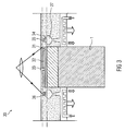
FIG 3 illustrates the cross section of a SLM process chamber arrangement showing the buildup of the proposed heat treatment device along with the repair of the device by SLM, -
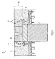
FIG 4 illustrates the cross section of a SLM process chamber arrangement showing the buildup of the proposed heat treatment device at the end of the SLM repair process, -
FIG 5 illustrates the cross section of a SLM process chamber arrangement showing post-SLM heat treatment of the component, -
FIG 6 illustrates the arrangement of the SLM process chamber when the post SLM heat treatment is complete, and -
FIG 7 illustrates the final repaired device taken out from the SLM process chamber arrangement. - The practical application of the invention can be found in, but not limited to the manufacture and repair of hot-gas components in a gas turbine or other high temperature applications. For example, turbine blades nevertheless are subject to damage as a result of operation in the gas turbine engines. This damage can be both mechanical in nature as well as metallurgical in nature. Turbine blades are expensive to produce, so that it is desirable from an economic standpoint to repair the blades rather than replace them whenever possible.
-
FIG 1 illustrates thecross section 10 of a SLM process chamber arrangement in prior art, for performing SLM of a device to be repaired.Device 1 is an item to be repaired, perceived without specific requirements concerning heat treatment or cooling.FIG 1 , shows a SLM set-up for repair, shown when first metallic powder layer, for example powder made of alloys or super alloys, is applied to the surface of the device. The arrangement has got aholder 2 specifically adapted for holding the device or product to be repaired. The holder circumferentially holds the device in place for the SLM process. During the SLM process, the holder is moved down in steps shown by thearrow 3 to enable the SLM of multiple layers on the device. In said arrangement alayer 4, with a specific thickness for example 20 or 30 microns or even more based on the requirement is laid over the surface of the device to be repaired. The actual SLM happens inside aprocess chamber 5, where alaser beam 6 from anoptical system 7, produces alocal melting spot 8 where themetallic powder 9 is fused to an underlying material or substrate of the device to be repaired. Typically, theprocess chamber 5 is filled by an inert gas to avoid oxidation of the local melt pool during the process. In the said scenario the first layer is fused on top of the surface of the device to be repaired and then on top of the just previously sintered layer, repeatedly till the whole component is built up. - Practically, the portion of the device that needs a repair would more or less be a small area when compared to the whole device. Generally, for the repair using SLM the device should undergo a pre-preparation to start the SLM process. It is common to mill off or grind off the region to be repaired, before rebuilding the same or upgrading or changing the geometry by the SLM process.
-
FIG 2 illustrates thecross section 20 of a SLM chamber arrangement of the proposed SLM process according to one embodiment of the invention prior to actual SLM. The arrangement shows the setup of the proposed SLM process, after one powder layer is applied.Device 1 is the corresponding component shown inFIG 1 , which needs to be repaired and which is perceived with specific requirements concerning local heat treatment and local cooling. Afirst section 21 is the region in thedevice 1 which shall remain relatively cool, since this section could include heat sensitive elements, for example like sensors, surface coatings that need protection or materials that respond to heat treatment with decreased material properties. Because of the heat there is possibility of the section getting oxidized, deformed or developing bend. Hence to avoid this unwanted issues, cooling of the region is required, which is provided by a cooling arrangement. Thedevice 1 has got asecond section 22, which requires moderate post-process heat treatment since it is going to be the heat affected region during the SLM process. In the arrangement, the cooling arrangement is shown to have a specifically modifiedholder 23. The integratedcooling channels 28 are formed, to accommodate acooling inlet 24 to let a cooling medium into the holder and acooling drain 25, for draining out cooling medium from theholder 23. Theholder 23 circumferentially encloses thedevice 1. During the SLM process or at the subsequent heat treatment, or at both the times the cooling medium absorbs heat conducted into the cooling medium through theholder 23. The hot cooling medium is then continuously drained out and fresh supply of cooling medium is maintained using a reservoir and supply mechanism, which is not shown in theFIG 2 . The cooling medium could be a gas or a liquid. Theholder 23 is made of an electrically and magnetically insulating material. For example, the material used could be, but not limited to plastic, bakelite or ceramic. Theholder 23 comprises anextended region 27 circumferentially encircling thedevice 1, having ametallic surface coating 29 on the top flat surface, which can support the buildup of a heat treatment device, which will be discussed further. The cross section of the extendedregion 27 is seen in the shape of a symmetrical "cup" in theFIG 2 , but could also be realized in some other shape too. The height of the extended region defines a minimum offset 26, up to which ametallic powder 9 is filled in theSLM chamber 5. - The offset 26 is so adjusted and chosen to provide a layer of the
metallic powder 9 on top of thedevice 1, for SLM to happen when the laser beam scans through themetallic powder 9. Themetallic powder 9 forms a layer on top of thedevice 1 once the SLM of the layer is done. Themetallic surface coating 29 further enables the built up of the heat treatment device on top of theholder 23 which is generally non-metallic. The bed formed by themetallic powder 9 also protects the heat sensitive section of thedevice 1 by providing both electrical and thermal insulation. The height of metallic powder bed, which is the offset 26, can be controlled to provide the said protection. -
FIG 3 illustrates thecross section 30 of a SLM chamber arrangement showing the buildup of the proposed heat treatment device along with the repair of the device by SLM. The SLM set-up inFIG 3 , shows two layers, i.e.layer 31 andlayer 32 which are added to thedevice 1 to form part of a component that need to be manufactured on the saiddevice 1 as part of the repair process. Athird layer 33 is already applied, which will form part of the component, when fused by SLM. Simultaneously during the SLM of thelayer 31, anotherlayer 34 is built around the component, having itsbase 36 on the flat surface of the extendedregion 27 of theholder 23. Similarly during the SLM of thelayer 32, anotherlayer 35 is built around the component. During SLM, theholder 23 is supplied with continuous supply of the cooling medium to cool the desired section of thedevice 1. -
FIG 4 illustrates thecross section 40 of a SLM chamber arrangement showing the buildup of the proposed heat treatment device at the end of the SLM repair process. The SLM set-up is shown for repairs, after the end of SLM repair process with theSLM process chamber 5 still completely filled withmetallic powder 9. The holder device is continuously cooled during the process. The buildup ofheat treatment device 42 gets completed with the end of the SLM of the component in the SLM repair process. Finally the heat treatment device which gets built on theholder 23 will be of any desired coil shape. Theheat treatment device 42 is spatially positioned in relation to thesintered component 43, such that saidheat treatment device 42 can provide the heat treatment to thecomponent 43 without directly coming in contact with thecomponent 43. The coil shapedheat treatment device 42 circumferentially encloses thecomponent 43. The arrangement shows theheat treatment device 42 in cross section, which is built circumferentially around thecomponent 43. Thecomponent 43 is shown to have multiple layers added on top of thedevice 1 to be repaired. The regions where the SLM is required for the buildup of theheat treatment device 42 can be controlled based on the shape of thecomponent 43 to be manufactured, so as to have a similar profile build around thecomponent 43 to have an effective heat treatment, when theheat treatment device 42 is active. - The
metallic powder 9 gets accumulated in theSLM chamber 5 forming alayer 41, which corresponds to the height of the buildupheat treatment device 42. -
FIG 5 illustrates thecross section 50 of a SLM process chamber arrangement showing post-SLM heat treatment of the component. The arrangement illustrates SLM set-up for repairs, shown with thesame SLM chamber 5 as depicted inFIG 4 , partly emptied frommetallic powder 9, till the offset 26. Theheat treatment device 42 is connected to anelectric power source 51, for example an ac power source. Theelectric connectors 52, transmits the electric current to theheat treatment device 42. The transmission of energy happens through electro-magnetic induction 53 as shown in theFIG 5 . The post SLM heat treatment is provided after themetallic powder 9 is removed down to the height of the offset 26. During the said process the remainingmetallic powder 9 will act as electro magnetic insulator, thereby safeguarding thedevice 1 to be repaired from any electro-magnetically induced currents. During the said process, theholder 23 is continuously cooled. -
FIG 6 illustratescross section 60 of a SLM chamber arrangement when the post SLM heat treatment is complete. The arrangement shows the sameSLM process chamber 5 as depicted inFIG 4 , completely emptied frommetallic powder 9. Theelectric power source 51 and theelectric connectors 52 are also detached from theheat treatment device 42. As long as the device to be repaired is in the SLM process chamber the cooling could be continued. Finally, thecomponent 43 has undergone a beneficial heat treatment and thesection 22 has experienced limited heating due to the presence of theholder 23 nearby and its cooling effect ondevice 1. -
FIG 7 illustrates the repaired device taken out from theSLM chamber 5. Once the heat treatment is over, theheat treatment device 42 is removed from theholder 23 and discarded. The holder could be reused if there is a similar device to be repaired. Themetallic surface coating 29 of the extendedregion 27 of theholder 23 could be machined and renewed prior to reuse. The cooling is switched off while performing the said process. At the end of the SLM process, heat treatment and cooling a repaired component with the intended properties is obtained. - Summarizing, the present invention introduces a method of manufacturing a component by SLM and performing the required heat treatment in the SLM chamber. The method avoids transporting the SLM machined components, devices or products to an alternate environment for the required heat treatment. The proposed invention also provides the required cooling for the regions of a device that needs cooling also, which is again provided within the SLM chamber itself.
- Although the invention has been described with reference to specific embodiments, this description is not meant to be construed in a limiting sense. Various modifications of the disclosed embodiments, as well as alternate embodiments of the invention, will become apparent to persons skilled in the art upon reference to the description of the invention. It is therefore contemplated that such modifications can be made without departing from the embodiments of the present invention as defined.
Claims (15)
- A method for manufacturing a component (43) by selective laser melting comprising:- building a heat treatment device (42) adapted to provide a heat treatment to the component (43) as part of the same selective laser melting for manufacturing the component (43); and- providing a heat treatment to the component (43) by the heat treatment device (42).
- The method according to claim 1, wherein the heat treatment device (42) is spatially positioned in relation to the component (43), such that said heat treatment device (42) is adapted to provide the heat treatment to the component (43).
- The method according to claim 1 or 2, wherein the component (43) is made of an electrically and thermally conductive material.
- The method according to any of the claims 1 to 3, wherein the heat treatment device (42) is coil shaped.
- The method according to any of the claims 1 to 4, wherein the coil shaped heat treatment device (42) circumferentially encircles the component (43).
- The method according to any of the claims 1 to 5, wherein the component (43) is manufactured onto a device (1), for repairing said device (1).
- The method according to claim 6, further comprises providing cooling to the device by a cooling arrangement.
- The method according to claim 7, wherein the cooling arrangement further comprises a holder (23) for holding the component and having an integrated cooling channel (28) through which a cooling medium flows.
- The method according to claim 8, wherein the holder (23) is made of an electrically and magnetically insulating material.
- The method according to any of the claims 7 to 9, wherein cooling is provided to the device (1) during SLM of the component (43) and heat treatment of the component (43).
- The method according to any of the claims 1 to 10, wherein the heat treatment is provided to the component (43) after selective laser melting of the component (43).
- The method according to any of the claims 1 to 11, wherein building the heat treatment device (42) comprises supporting a base (36) of said heat treatment device by the holder (23).
- The method according to claim 12, wherein supporting said heat treatment device by the holder comprises supporting said heat treatment device at its base (36) by an extended region (27) of a the holder (23), said extended region (27) having a specific height and a flat surface with metallic surface coating (29) encircling the component (43).
- The method according to any of the claims 1 to 13, wherein the heat treatment is performed in a selective laser melting chamber (5).
- The method according to any of the claims 1 to 14, wherein the heat treatment is an inductive heat treatment.
Priority Applications (6)
| Application Number | Priority Date | Filing Date | Title |
|---|---|---|---|
| EP10008192A EP2415552A1 (en) | 2010-08-05 | 2010-08-05 | A method for manufacturing a component by selective laser melting |
| US13/813,968 US9073150B2 (en) | 2010-08-05 | 2011-07-20 | Method for manufacturing a component by selective laser melting |
| CN201180038670.7A CN103068516B (en) | 2010-08-05 | 2011-07-20 | For the method by selective laser melting manufacture component |
| ES11740867.4T ES2480294T3 (en) | 2010-08-05 | 2011-07-20 | Method for manufacturing a component by selective laser fusion |
| EP11740867.4A EP2601006B1 (en) | 2010-08-05 | 2011-07-20 | A method for manufacturing a component by selective laser melting |
| PCT/EP2011/062457 WO2012016836A1 (en) | 2010-08-05 | 2011-07-20 | A method for manufacturing a component by selective laser melting |
Applications Claiming Priority (1)
| Application Number | Priority Date | Filing Date | Title |
|---|---|---|---|
| EP10008192A EP2415552A1 (en) | 2010-08-05 | 2010-08-05 | A method for manufacturing a component by selective laser melting |
Publications (1)
| Publication Number | Publication Date |
|---|---|
| EP2415552A1 true EP2415552A1 (en) | 2012-02-08 |
Family
ID=43533300
Family Applications (2)
| Application Number | Title | Priority Date | Filing Date |
|---|---|---|---|
| EP10008192A Withdrawn EP2415552A1 (en) | 2010-08-05 | 2010-08-05 | A method for manufacturing a component by selective laser melting |
| EP11740867.4A Not-in-force EP2601006B1 (en) | 2010-08-05 | 2011-07-20 | A method for manufacturing a component by selective laser melting |
Family Applications After (1)
| Application Number | Title | Priority Date | Filing Date |
|---|---|---|---|
| EP11740867.4A Not-in-force EP2601006B1 (en) | 2010-08-05 | 2011-07-20 | A method for manufacturing a component by selective laser melting |
Country Status (5)
| Country | Link |
|---|---|
| US (1) | US9073150B2 (en) |
| EP (2) | EP2415552A1 (en) |
| CN (1) | CN103068516B (en) |
| ES (1) | ES2480294T3 (en) |
| WO (1) | WO2012016836A1 (en) |
Cited By (10)
| Publication number | Priority date | Publication date | Assignee | Title |
|---|---|---|---|---|
| WO2014099114A1 (en) * | 2012-12-18 | 2014-06-26 | United Technologies Corporation | Additive manufacturing using partially sintered layers |
| WO2014206573A2 (en) | 2013-06-28 | 2014-12-31 | Trumpf Gmbh + Co. Kg | Method and processing machine for creating a three-dimensional component by selective laser melting |
| RU2562722C1 (en) * | 2014-03-26 | 2015-09-10 | Федеральное государственное бюджетное образовательное учреждение высшего профессионального образования "Московский государственный технологический университет "СТАНКИН" (ФГБОУ ВПО МГТУ "СТАНКИН") | Method of production of articles with complex shape out of powder systems |
| CN105014073A (en) * | 2015-08-18 | 2015-11-04 | 上海航天精密机械研究所 | TC4 titanium alloy laser selective melting material additive manufacturing and heat treatment method |
| EP3156152A1 (en) | 2015-10-12 | 2017-04-19 | Siemens Aktiengesellschaft | Adaption mechanism, additive manufacturing apparatus with adaption mechanism and method of additively manufacturing of a component |
| EP3159080A1 (en) | 2015-10-19 | 2017-04-26 | Siemens Aktiengesellschaft | Method of adjusting an additive manufacturing apparatus, method of manufacturing and setup |
| US9649690B2 (en) | 2014-02-25 | 2017-05-16 | General Electric Company | System having layered structure and method of making the same |
| DE102016203680A1 (en) * | 2016-03-07 | 2017-09-07 | Siemens Aktiengesellschaft | Device for carrying out a selective laser melting process and component produced therewith |
| WO2018145912A1 (en) * | 2017-02-08 | 2018-08-16 | Siemens Aktiengesellschaft | Method and device for the powder bed-based additive building up of a plurality of identical components |
| CN108746621A (en) * | 2018-05-29 | 2018-11-06 | 华中科技大学 | A kind of self-cleaning porous network structure follow-cooling passageway and its manufacturing process |
Families Citing this family (83)
| Publication number | Priority date | Publication date | Assignee | Title |
|---|---|---|---|---|
| EP2700459B1 (en) | 2012-08-21 | 2019-10-02 | Ansaldo Energia IP UK Limited | Method for manufacturing a three-dimensional article |
| WO2014203275A2 (en) | 2013-06-18 | 2014-12-24 | Cadila Healthcare Limited | An improved process for the preparation of apixaban and intermediates thereof |
| TWI511823B (en) * | 2013-12-20 | 2015-12-11 | 財團法人工業技術研究院 | Apparatus and method for controlling the additive manufacturing |
| US10076786B2 (en) * | 2014-01-22 | 2018-09-18 | Siemens Energy, Inc. | Method for processing a part with an energy beam |
| US9896944B2 (en) * | 2014-04-18 | 2018-02-20 | Siemens Energy, Inc. | Forming a secondary structure directly onto a turbine blade |
| DE102014222302A1 (en) * | 2014-10-31 | 2016-05-04 | Siemens Aktiengesellschaft | Producing a component by selective laser melting |
| FR3028436B1 (en) * | 2014-11-14 | 2019-04-05 | Safran Aircraft Engines | PROCESS FOR PRODUCING A TURBOMACHINE PIECE |
| CN105386037B (en) * | 2015-11-05 | 2018-03-09 | 华中科技大学 | A kind of method that functionally gradient part is shaped using precinct laser fusion forming technique |
| FR3043577B1 (en) | 2015-11-17 | 2022-06-17 | Snecma | METHOD FOR MANUFACTURING A BLADE PREFORM, A BLADE AND A DISTRIBUTOR SECTOR BY SELECTIVE POWDER BED FUSION |
| US10239157B2 (en) | 2016-04-06 | 2019-03-26 | General Electric Company | Additive machine utilizing rotational build surface |
| CN105642897B (en) * | 2016-04-11 | 2017-11-24 | 西安赛隆金属材料有限责任公司 | A kind of cooling device of electron beam selective melting former |
| WO2018001705A1 (en) | 2016-07-01 | 2018-01-04 | Siemens Aktiengesellschaft | Device for additive manufacturing, and method |
| DE102016214229A1 (en) | 2016-08-02 | 2018-02-08 | Siemens Aktiengesellschaft | Method for additive production and component for a turbomachine |
| PL3278908T3 (en) | 2016-08-02 | 2020-07-27 | Siemens Aktiengesellschaft | Support structure, method of providing the same and method of additively manufacturing |
| EP3281725A1 (en) | 2016-08-09 | 2018-02-14 | Siemens Aktiengesellschaft | Method of additive manufacturing and computer readable medium |
| DE102016215389A1 (en) | 2016-08-17 | 2018-02-22 | Siemens Aktiengesellschaft | Method for the additive production of a component and device |
| US10168114B2 (en) | 2016-08-30 | 2019-01-01 | Hamilton Sundstrand Corporation | Integral drain assembly for a heat exchanger and method of forming |
| DE102016120044A1 (en) * | 2016-10-20 | 2018-04-26 | Cl Schutzrechtsverwaltungs Gmbh | Device for the additive production of three-dimensional objects |
| DE102016222210A1 (en) | 2016-11-11 | 2018-05-17 | Siemens Aktiengesellschaft | Process for additive production with designation of a construction platform by reference points |
| DE102016222555A1 (en) | 2016-11-16 | 2018-05-17 | Siemens Aktiengesellschaft | Method for additive production of a component and computer-readable medium |
| DE102016224060A1 (en) | 2016-12-02 | 2018-06-07 | Siemens Aktiengesellschaft | Method for the additive production of a component with a supporting structure and a reduced energy density |
| GB201700170D0 (en) * | 2017-01-06 | 2017-02-22 | Rolls Royce Plc | Manufacturing method and apparatus |
| DE102017201084A1 (en) | 2017-01-24 | 2018-07-26 | Siemens Aktiengesellschaft | Process for additive production and coating apparatus |
| EP3354632A1 (en) | 2017-01-25 | 2018-08-01 | Siemens Aktiengesellschaft | Method to additively manufacture a fiber-reinforced ceramic matrix composite |
| US10702958B2 (en) * | 2017-02-22 | 2020-07-07 | General Electric Company | Method of manufacturing turbine airfoil and tip component thereof using ceramic core with witness feature |
| EP3366392A1 (en) | 2017-02-23 | 2018-08-29 | Siemens Aktiengesellschaft | Build platform for additive manufacturing adapted for heat treatment process |
| EP3388907A1 (en) | 2017-04-13 | 2018-10-17 | Siemens Aktiengesellschaft | Method of providing a dataset for the additive manufacture and corresponding quality control method |
| EP3406371A1 (en) | 2017-05-22 | 2018-11-28 | Siemens Aktiengesellschaft | Method of relieving mechanical stress in additive manufacturing |
| DE102017208651A1 (en) | 2017-05-22 | 2018-11-22 | Siemens Aktiengesellschaft | Manufacturing module for additive manufacturing |
| DE102017208699A1 (en) | 2017-05-23 | 2018-11-29 | Siemens Aktiengesellschaft | Method for material diagnosis in additive manufacturing |
| DE102017210718A1 (en) | 2017-06-26 | 2018-12-27 | Siemens Aktiengesellschaft | Suction device for additive manufacturing |
| DE102017210909A1 (en) | 2017-06-28 | 2019-01-03 | Siemens Aktiengesellschaft | Method for the additive production of a component by means of auxiliary structure |
| EP3422281A1 (en) | 2017-06-30 | 2019-01-02 | Siemens Aktiengesellschaft | Blockchain database for additive manufacturing |
| DE102017211657A1 (en) | 2017-07-07 | 2019-01-10 | Siemens Aktiengesellschaft | Device for the additive production of a component with inert gas guidance and method |
| DE102017212110A1 (en) | 2017-07-14 | 2019-01-17 | Siemens Aktiengesellschaft | Process for an additive to be produced component with a predetermined surface structure |
| DE102017213378A1 (en) | 2017-08-02 | 2019-02-07 | Siemens Aktiengesellschaft | Method for forming a defined surface roughness |
| EP3441162A1 (en) | 2017-08-11 | 2019-02-13 | Siemens Aktiengesellschaft | Method of additively manufacturing a structure on a pre-existing component out of the powder bed |
| DE102017214060A1 (en) | 2017-08-11 | 2019-02-14 | Siemens Aktiengesellschaft | Functional structure and component for a turbomachine |
| EP3450055A1 (en) | 2017-08-30 | 2019-03-06 | Siemens Aktiengesellschaft | Method for additively manufacturing a tip structure on a pre-existing part |
| EP3461571A1 (en) | 2017-10-02 | 2019-04-03 | Siemens Aktiengesellschaft | Method for irradiating a powder coating in additive manufacturing with continuously defined manufacturing parameters |
| EP3461572A1 (en) | 2017-10-02 | 2019-04-03 | Siemens Aktiengesellschaft | Build plate for additive manufacturing and method |
| EP3489376A1 (en) | 2017-11-24 | 2019-05-29 | Siemens Aktiengesellschaft | Alloy for gas turbine applications with high oxidation resistance |
| EP3498401A1 (en) | 2017-12-18 | 2019-06-19 | Siemens Aktiengesellschaft | Method of additively manufacturing a component, an apparatus and computer program product |
| DE102017223223A1 (en) | 2017-12-19 | 2019-06-19 | Siemens Aktiengesellschaft | Method for the additive construction of a structure and computer program product |
| EP3508690A1 (en) | 2018-01-09 | 2019-07-10 | Siemens Aktiengesellschaft | Turbine blade and method for its manufacture |
| EP3511093A1 (en) | 2018-01-16 | 2019-07-17 | Siemens Aktiengesellschaft | Method of removing an excess material from a cavity, additive manufacturing method and part |
| EP3520929A1 (en) | 2018-02-06 | 2019-08-07 | Siemens Aktiengesellschaft | Method for selectively irradiating a material layer, manufacturing method and computer program product |
| CN108620585B (en) * | 2018-04-09 | 2021-08-10 | 上海大学 | Additive manufacturing device capable of controlling magnetic field and conveying parent metal |
| DE102018207248A1 (en) | 2018-05-09 | 2019-11-14 | Siemens Aktiengesellschaft | Process for the additive production of a component with oxidic dispersion reinforcement and corresponding component |
| EP3569332A1 (en) | 2018-05-14 | 2019-11-20 | Siemens Aktiengesellschaft | Method of providing a dataset, additive manufacturing method, computer program product and computer readable medium |
| DE102018208400A1 (en) | 2018-05-28 | 2019-11-28 | Siemens Aktiengesellschaft | Apparatus for heating a component material, additive manufacturing equipment, and additive manufacturing method |
| EP3575017A1 (en) | 2018-05-30 | 2019-12-04 | Siemens Aktiengesellschaft | Additive manufacturing procedure and setup |
| CN108746613B (en) * | 2018-05-31 | 2019-11-22 | 华中科技大学 | A kind of online heat treatment system of selective laser fusing |
| DE102018210397A1 (en) | 2018-06-26 | 2020-01-02 | Siemens Aktiengesellschaft | Method for additive manufacturing of a structure with coolant guidance, component and device |
| EP3587005A1 (en) | 2018-06-26 | 2020-01-01 | Siemens Aktiengesellschaft | Control method for layerwise additive manufacturing, computer program product and control apparatus |
| DE102018212480A1 (en) | 2018-07-26 | 2020-01-30 | Siemens Aktiengesellschaft | Additive manufacturing process with selective irradiation and simultaneous application as well as heat treatment |
| DE102018212677A1 (en) | 2018-07-30 | 2020-01-30 | Siemens Aktiengesellschaft | Process for joining superalloys and composite components |
| EP3608039A1 (en) | 2018-08-07 | 2020-02-12 | Siemens Aktiengesellschaft | Method of irradiating for additive production with predetermined trajectory |
| US11426818B2 (en) | 2018-08-10 | 2022-08-30 | The Research Foundation for the State University | Additive manufacturing processes and additively manufactured products |
| EP3639951A1 (en) | 2018-10-17 | 2020-04-22 | Siemens Aktiengesellschaft | Recoater head for localized deposition of a powdery base material in additive manufacturing |
| EP3656490A1 (en) | 2018-11-22 | 2020-05-27 | Siemens Aktiengesellschaft | Method for providing data for an adaptive temperature control system |
| EP3656489A1 (en) | 2018-11-22 | 2020-05-27 | Siemens Aktiengesellschaft | Control method for additive manufacturing |
| EP3705211A1 (en) | 2019-03-05 | 2020-09-09 | Siemens Aktiengesellschaft | Method for heating a base material in additive manufacturing |
| CN110116207A (en) * | 2019-05-14 | 2019-08-13 | 中国航发北京航空材料研究院 | The intensifying device and method of selective laser fusing increasing material manufacturing component |
| DE102019207553A1 (en) | 2019-05-23 | 2020-11-26 | Siemens Aktiengesellschaft | Manufacturing process with additive manufacturing of a shaped body, manufacture of a mold and heat treatment |
| EP3760345A1 (en) | 2019-07-04 | 2021-01-06 | Siemens Aktiengesellschaft | Computer-implemented method of calculation and method of supporting for additive manufacturing |
| US11731198B2 (en) * | 2019-08-20 | 2023-08-22 | Rosemount Aerospace Inc. | Additive manufacturing system including an optical isolator |
| DE102019213214A1 (en) | 2019-09-02 | 2021-03-04 | Siemens Aktiengesellschaft | Nickel-based superalloy, also suitable for additive manufacturing, process and product |
| DE102019213990A1 (en) | 2019-09-13 | 2021-03-18 | Siemens Aktiengesellschaft | Nickel-based alloy for additive manufacturing, process and product |
| DE102019214667A1 (en) | 2019-09-25 | 2021-03-25 | Siemens Aktiengesellschaft | Component with an area to be cooled and means for the additive manufacture of the same |
| EP3804883A1 (en) | 2019-10-11 | 2021-04-14 | Siemens Aktiengesellschaft | Method of applying a plurality of energy beams in additive manufacturing |
| CN110918987B (en) * | 2019-10-30 | 2022-05-03 | 株洲航发动科南方燃气轮机有限公司 | Preparation method of 3D printing turbine blade and turbine guide blade |
| DE102019217434A1 (en) | 2019-11-12 | 2021-05-12 | Siemens Aktiengesellschaft | Process for the layer-by-layer additive manufacturing of a composite material |
| DE102019218377A1 (en) | 2019-11-27 | 2021-05-27 | Siemens Aktiengesellschaft | Method for selectively irradiating a powder layer in additive manufacturing with a first and a second irradiation pattern |
| EP3848135A1 (en) | 2020-01-10 | 2021-07-14 | Siemens Aktiengesellschaft | Scanning strategy for volume support in additive manufacturing |
| DE102020201450A1 (en) | 2020-02-06 | 2021-08-12 | Siemens Aktiengesellschaft | Method for producing a support structure in additive manufacturing, computer program product and control |
| DE102020201448A1 (en) | 2020-02-06 | 2021-08-12 | Siemens Aktiengesellschaft | Additively manufactured turbine blade with anti-twist device and adjustment process |
| DE102020202089A1 (en) | 2020-02-19 | 2021-08-19 | Siemens Aktiengesellschaft | Platform structure for a turbine blade and additive manufacturing process |
| US11396063B2 (en) | 2020-03-23 | 2022-07-26 | Rosemount Aerospace Inc. | Systems and methods for in process heating for direct energy deposition applications |
| EP3936260A1 (en) | 2020-07-06 | 2022-01-12 | Siemens Aktiengesellschaft | Radiation strategy for a structure made by means of additive manufacture |
| DE102020209239A1 (en) | 2020-07-22 | 2022-01-27 | Siemens Aktiengesellschaft | Irradiation strategy for a coolable, additively manufactured structure |
| EP4015111A1 (en) | 2020-12-17 | 2022-06-22 | Siemens Energy Global GmbH & Co. KG | Variable layer thickness additive manufacturing |
| EP4023365A1 (en) | 2021-01-05 | 2022-07-06 | Siemens Energy Global GmbH & Co. KG | Support strategy for thin-walled additive structure |
Citations (4)
| Publication number | Priority date | Publication date | Assignee | Title |
|---|---|---|---|---|
| US5597589A (en) * | 1986-10-17 | 1997-01-28 | Board Of Regents, The University Of Texas System | Apparatus for producing parts by selective sintering |
| US20010014403A1 (en) * | 1997-08-12 | 2001-08-16 | Lawrence Evans Brown | Method and apparatus for making components by direct laser processing |
| WO2001081031A1 (en) * | 2000-04-27 | 2001-11-01 | Arcam Ab | Device and arrangement for producing a three-dimensional object |
| WO2010026397A1 (en) * | 2008-09-05 | 2010-03-11 | Mtt Technologies Limited | Additive manufacturing apparatus with a chamber and a removably-mountable optical module; method of preparing a laser processing apparatus with such removably-mountable optical module |
Family Cites Families (7)
| Publication number | Priority date | Publication date | Assignee | Title |
|---|---|---|---|---|
| US4818562A (en) * | 1987-03-04 | 1989-04-04 | Westinghouse Electric Corp. | Casting shapes |
| CN1026219C (en) | 1992-05-20 | 1994-10-19 | 中国科学院金属腐蚀与防护研究所 | Technology of laser contour melting cast for surface treatment of aerial blade |
| JP2004122490A (en) | 2002-09-30 | 2004-04-22 | Matsushita Electric Works Ltd | Method for manufacturing three-dimensionally shaped article |
| JP2004130314A (en) | 2002-10-08 | 2004-04-30 | Toshiba Corp | Method for suppressing occurrence of stress corrosion cracking |
| CN1439476A (en) * | 2003-02-24 | 2003-09-03 | 天津大学 | Build-up welding process for repairing cold rolling intermediate roller |
| CN100402223C (en) * | 2005-06-22 | 2008-07-16 | 中国科学院金属研究所 | Crack repair process for high-pressure turbine blade tip in gas turbine |
| DE102006058949A1 (en) * | 2006-12-14 | 2008-06-19 | Inno-Shape Gmbh | Device and method for repairing or producing blade tips of blades of a gas turbine, in particular an aircraft engine |
-
2010
- 2010-08-05 EP EP10008192A patent/EP2415552A1/en not_active Withdrawn
-
2011
- 2011-07-20 CN CN201180038670.7A patent/CN103068516B/en not_active Expired - Fee Related
- 2011-07-20 EP EP11740867.4A patent/EP2601006B1/en not_active Not-in-force
- 2011-07-20 US US13/813,968 patent/US9073150B2/en not_active Expired - Fee Related
- 2011-07-20 WO PCT/EP2011/062457 patent/WO2012016836A1/en active Application Filing
- 2011-07-20 ES ES11740867.4T patent/ES2480294T3/en active Active
Patent Citations (4)
| Publication number | Priority date | Publication date | Assignee | Title |
|---|---|---|---|---|
| US5597589A (en) * | 1986-10-17 | 1997-01-28 | Board Of Regents, The University Of Texas System | Apparatus for producing parts by selective sintering |
| US20010014403A1 (en) * | 1997-08-12 | 2001-08-16 | Lawrence Evans Brown | Method and apparatus for making components by direct laser processing |
| WO2001081031A1 (en) * | 2000-04-27 | 2001-11-01 | Arcam Ab | Device and arrangement for producing a three-dimensional object |
| WO2010026397A1 (en) * | 2008-09-05 | 2010-03-11 | Mtt Technologies Limited | Additive manufacturing apparatus with a chamber and a removably-mountable optical module; method of preparing a laser processing apparatus with such removably-mountable optical module |
Cited By (15)
| Publication number | Priority date | Publication date | Assignee | Title |
|---|---|---|---|---|
| WO2014099114A1 (en) * | 2012-12-18 | 2014-06-26 | United Technologies Corporation | Additive manufacturing using partially sintered layers |
| US10245681B2 (en) | 2013-06-28 | 2019-04-02 | Trumpf Gmbh + Co. Kg | Generating a three-dimensional component by selective laser melting |
| WO2014206573A2 (en) | 2013-06-28 | 2014-12-31 | Trumpf Gmbh + Co. Kg | Method and processing machine for creating a three-dimensional component by selective laser melting |
| DE102013212620A1 (en) | 2013-06-28 | 2014-12-31 | Trumpf Gmbh + Co. Kg | Method and machine for generating a three-dimensional component by selective laser melting |
| WO2014206573A3 (en) * | 2013-06-28 | 2015-04-16 | Trumpf Gmbh + Co. Kg | Method and processing machine for creating a three-dimensional component by selective laser melting |
| US11137143B2 (en) | 2014-02-25 | 2021-10-05 | General Electric Company | System having layered structure and method of making the same |
| US9649690B2 (en) | 2014-02-25 | 2017-05-16 | General Electric Company | System having layered structure and method of making the same |
| RU2562722C1 (en) * | 2014-03-26 | 2015-09-10 | Федеральное государственное бюджетное образовательное учреждение высшего профессионального образования "Московский государственный технологический университет "СТАНКИН" (ФГБОУ ВПО МГТУ "СТАНКИН") | Method of production of articles with complex shape out of powder systems |
| CN105014073A (en) * | 2015-08-18 | 2015-11-04 | 上海航天精密机械研究所 | TC4 titanium alloy laser selective melting material additive manufacturing and heat treatment method |
| EP3156152A1 (en) | 2015-10-12 | 2017-04-19 | Siemens Aktiengesellschaft | Adaption mechanism, additive manufacturing apparatus with adaption mechanism and method of additively manufacturing of a component |
| EP3159080A1 (en) | 2015-10-19 | 2017-04-26 | Siemens Aktiengesellschaft | Method of adjusting an additive manufacturing apparatus, method of manufacturing and setup |
| DE102016203680A1 (en) * | 2016-03-07 | 2017-09-07 | Siemens Aktiengesellschaft | Device for carrying out a selective laser melting process and component produced therewith |
| WO2018145912A1 (en) * | 2017-02-08 | 2018-08-16 | Siemens Aktiengesellschaft | Method and device for the powder bed-based additive building up of a plurality of identical components |
| CN110382140A (en) * | 2017-02-08 | 2019-10-25 | 西门子股份公司 | Based on powder bed multiple same parts increase with the method and apparatus of material building |
| CN108746621A (en) * | 2018-05-29 | 2018-11-06 | 华中科技大学 | A kind of self-cleaning porous network structure follow-cooling passageway and its manufacturing process |
Also Published As
| Publication number | Publication date |
|---|---|
| CN103068516A (en) | 2013-04-24 |
| WO2012016836A1 (en) | 2012-02-09 |
| US9073150B2 (en) | 2015-07-07 |
| US20130199013A1 (en) | 2013-08-08 |
| EP2601006B1 (en) | 2014-06-18 |
| ES2480294T3 (en) | 2014-07-25 |
| CN103068516B (en) | 2016-01-13 |
| EP2601006A1 (en) | 2013-06-12 |
Similar Documents
| Publication | Publication Date | Title |
|---|---|---|
| EP2601006B1 (en) | A method for manufacturing a component by selective laser melting | |
| US10245681B2 (en) | Generating a three-dimensional component by selective laser melting | |
| US8344298B2 (en) | Process of measuring the temperature of coil end part and the stator core | |
| US20180079033A1 (en) | Plant For An Additive Production Method | |
| US10875258B2 (en) | Multi-frequency induction heating of generatively produced components | |
| Dalaee et al. | Experimental and numerical study of the influence of induction heating process on build rates Induction Heating-assisted laser Direct Metal Deposition (IH-DMD) | |
| US9616458B2 (en) | Sintering and laser fusion device, comprising a means for heating powder by induction | |
| US10285222B2 (en) | Method and device for generatively producing at least one component area | |
| US20130015609A1 (en) | Functionally graded additive manufacturing with in situ heat treatment | |
| GB2587158A (en) | Support Structures for additive manufacturing techniques | |
| JP2018003087A (en) | Three-dimensional molding apparatus, and method for manufacturing three-dimensionally molded article | |
| EP2444194A1 (en) | Method for beam welding on components | |
| JP2008159759A (en) | Heat treating method and apparatus using induction heating | |
| Lanin et al. | Induction devices for assembly soldering in electronics | |
| CN106903311A (en) | A kind of electromagnetic induction selective laser fusing powder bed on-line heating system and method | |
| JP4727552B2 (en) | Stator coil and core heating apparatus and heating method | |
| CN112045294A (en) | Rigid restraint thermal self-pressure diffusion connection method and device for local induction heating | |
| JP2010510070A (en) | Heat treatment method and apparatus for welded joint | |
| EP2900036B1 (en) | High-frequency induction heating device and processing device | |
| JP6050141B2 (en) | Hardfacing welding apparatus and method | |
| US20130270259A1 (en) | Device and method for inductively heating metal components during welding, using a cooled flexible induction element | |
| JP7274215B2 (en) | Method and apparatus for manufacturing hardened sheet metal products | |
| JP4261331B2 (en) | Induction heating molding equipment | |
| JP2005179084A (en) | Induction heating molding apparatus | |
| CN114309951B (en) | Repair welding method for mirror substrate and surface treatment method for mirror substrate |
Legal Events
| Date | Code | Title | Description |
|---|---|---|---|
| AK | Designated contracting states |
Kind code of ref document: A1 Designated state(s): AL AT BE BG CH CY CZ DE DK EE ES FI FR GB GR HR HU IE IS IT LI LT LU LV MC MK MT NL NO PL PT RO SE SI SK SM TR |
|
| AX | Request for extension of the european patent |
Extension state: BA ME RS |
|
| PUAI | Public reference made under article 153(3) epc to a published international application that has entered the european phase |
Free format text: ORIGINAL CODE: 0009012 |
|
| STAA | Information on the status of an ep patent application or granted ep patent |
Free format text: STATUS: THE APPLICATION IS DEEMED TO BE WITHDRAWN |
|
| 18D | Application deemed to be withdrawn |
Effective date: 20120809 |