EP2414031B1 - Haltering für sanitärarmaturen - Google Patents
Haltering für sanitärarmaturen Download PDFInfo
- Publication number
- EP2414031B1 EP2414031B1 EP10759451.7A EP10759451A EP2414031B1 EP 2414031 B1 EP2414031 B1 EP 2414031B1 EP 10759451 A EP10759451 A EP 10759451A EP 2414031 B1 EP2414031 B1 EP 2414031B1
- Authority
- EP
- European Patent Office
- Prior art keywords
- retainer
- sanitary
- members
- collet
- resilient
- Prior art date
- Legal status (The legal status is an assumption and is not a legal conclusion. Google has not performed a legal analysis and makes no representation as to the accuracy of the status listed.)
- Not-in-force
Links
- 238000000034 method Methods 0.000 claims description 14
- 230000006835 compression Effects 0.000 claims description 6
- 238000007906 compression Methods 0.000 claims description 6
- 239000000463 material Substances 0.000 description 6
- 230000005499 meniscus Effects 0.000 description 6
- 230000015572 biosynthetic process Effects 0.000 description 4
- 238000005755 formation reaction Methods 0.000 description 4
- 229910001220 stainless steel Inorganic materials 0.000 description 4
- 239000010935 stainless steel Substances 0.000 description 4
- 230000000284 resting effect Effects 0.000 description 3
- 230000000712 assembly Effects 0.000 description 2
- 238000000429 assembly Methods 0.000 description 2
- 238000012986 modification Methods 0.000 description 2
- 230000004048 modification Effects 0.000 description 2
- 239000004033 plastic Substances 0.000 description 2
- 229920003023 plastic Polymers 0.000 description 2
- VGGSQFUCUMXWEO-UHFFFAOYSA-N Ethene Chemical compound C=C VGGSQFUCUMXWEO-UHFFFAOYSA-N 0.000 description 1
- 239000005977 Ethylene Substances 0.000 description 1
- 235000013361 beverage Nutrition 0.000 description 1
- 229960000074 biopharmaceutical Drugs 0.000 description 1
- 230000008878 coupling Effects 0.000 description 1
- 238000010168 coupling process Methods 0.000 description 1
- 238000005859 coupling reaction Methods 0.000 description 1
- 238000012864 cross contamination Methods 0.000 description 1
- 238000004519 manufacturing process Methods 0.000 description 1
- 229910052755 nonmetal Inorganic materials 0.000 description 1
- 229920002981 polyvinylidene fluoride Polymers 0.000 description 1
- 230000001954 sterilising effect Effects 0.000 description 1
- 238000004659 sterilization and disinfection Methods 0.000 description 1
Images


Classifications
-
- A—HUMAN NECESSITIES
- A61—MEDICAL OR VETERINARY SCIENCE; HYGIENE
- A61M—DEVICES FOR INTRODUCING MEDIA INTO, OR ONTO, THE BODY; DEVICES FOR TRANSDUCING BODY MEDIA OR FOR TAKING MEDIA FROM THE BODY; DEVICES FOR PRODUCING OR ENDING SLEEP OR STUPOR
- A61M39/00—Tubes, tube connectors, tube couplings, valves, access sites or the like, specially adapted for medical use
- A61M39/10—Tube connectors; Tube couplings
- A61M39/16—Tube connectors; Tube couplings having provision for disinfection or sterilisation
-
- F—MECHANICAL ENGINEERING; LIGHTING; HEATING; WEAPONS; BLASTING
- F16—ENGINEERING ELEMENTS AND UNITS; GENERAL MEASURES FOR PRODUCING AND MAINTAINING EFFECTIVE FUNCTIONING OF MACHINES OR INSTALLATIONS; THERMAL INSULATION IN GENERAL
- F16L—PIPES; JOINTS OR FITTINGS FOR PIPES; SUPPORTS FOR PIPES, CABLES OR PROTECTIVE TUBING; MEANS FOR THERMAL INSULATION IN GENERAL
- F16L23/00—Flanged joints
- F16L23/04—Flanged joints the flanges being connected by members tensioned in the radial plane
-
- A—HUMAN NECESSITIES
- A61—MEDICAL OR VETERINARY SCIENCE; HYGIENE
- A61B—DIAGNOSIS; SURGERY; IDENTIFICATION
- A61B50/00—Containers, covers, furniture or holders specially adapted for surgical or diagnostic appliances or instruments, e.g. sterile covers
-
- F—MECHANICAL ENGINEERING; LIGHTING; HEATING; WEAPONS; BLASTING
- F16—ENGINEERING ELEMENTS AND UNITS; GENERAL MEASURES FOR PRODUCING AND MAINTAINING EFFECTIVE FUNCTIONING OF MACHINES OR INSTALLATIONS; THERMAL INSULATION IN GENERAL
- F16L—PIPES; JOINTS OR FITTINGS FOR PIPES; SUPPORTS FOR PIPES, CABLES OR PROTECTIVE TUBING; MEANS FOR THERMAL INSULATION IN GENERAL
- F16L37/00—Couplings of the quick-acting type
- F16L37/08—Couplings of the quick-acting type in which the connection between abutting or axially overlapping ends is maintained by locking members
- F16L37/12—Couplings of the quick-acting type in which the connection between abutting or axially overlapping ends is maintained by locking members using hooks, pawls, or other movable or insertable locking members
- F16L37/138—Couplings of the quick-acting type in which the connection between abutting or axially overlapping ends is maintained by locking members using hooks, pawls, or other movable or insertable locking members using an axially movable sleeve
-
- A—HUMAN NECESSITIES
- A61—MEDICAL OR VETERINARY SCIENCE; HYGIENE
- A61M—DEVICES FOR INTRODUCING MEDIA INTO, OR ONTO, THE BODY; DEVICES FOR TRANSDUCING BODY MEDIA OR FOR TAKING MEDIA FROM THE BODY; DEVICES FOR PRODUCING OR ENDING SLEEP OR STUPOR
- A61M39/00—Tubes, tube connectors, tube couplings, valves, access sites or the like, specially adapted for medical use
- A61M39/10—Tube connectors; Tube couplings
- A61M2039/1038—Union screw connectors, e.g. hollow screw or sleeve having external threads
-
- A—HUMAN NECESSITIES
- A61—MEDICAL OR VETERINARY SCIENCE; HYGIENE
- A61M—DEVICES FOR INTRODUCING MEDIA INTO, OR ONTO, THE BODY; DEVICES FOR TRANSDUCING BODY MEDIA OR FOR TAKING MEDIA FROM THE BODY; DEVICES FOR PRODUCING OR ENDING SLEEP OR STUPOR
- A61M39/00—Tubes, tube connectors, tube couplings, valves, access sites or the like, specially adapted for medical use
- A61M39/10—Tube connectors; Tube couplings
- A61M2039/1066—Tube connectors; Tube couplings having protection means, e.g. sliding sleeve to protect connector itself, shrouds to protect a needle present in the connector, protective housing, isolating sheath
-
- Y—GENERAL TAGGING OF NEW TECHNOLOGICAL DEVELOPMENTS; GENERAL TAGGING OF CROSS-SECTIONAL TECHNOLOGIES SPANNING OVER SEVERAL SECTIONS OF THE IPC; TECHNICAL SUBJECTS COVERED BY FORMER USPC CROSS-REFERENCE ART COLLECTIONS [XRACs] AND DIGESTS
- Y10—TECHNICAL SUBJECTS COVERED BY FORMER USPC
- Y10T—TECHNICAL SUBJECTS COVERED BY FORMER US CLASSIFICATION
- Y10T29/00—Metal working
- Y10T29/49—Method of mechanical manufacture
- Y10T29/49826—Assembling or joining
- Y10T29/49945—Assembling or joining by driven force fit
-
- Y—GENERAL TAGGING OF NEW TECHNOLOGICAL DEVELOPMENTS; GENERAL TAGGING OF CROSS-SECTIONAL TECHNOLOGIES SPANNING OVER SEVERAL SECTIONS OF THE IPC; TECHNICAL SUBJECTS COVERED BY FORMER USPC CROSS-REFERENCE ART COLLECTIONS [XRACs] AND DIGESTS
- Y10—TECHNICAL SUBJECTS COVERED BY FORMER USPC
- Y10T—TECHNICAL SUBJECTS COVERED BY FORMER US CLASSIFICATION
- Y10T29/00—Metal working
- Y10T29/53—Means to assemble or disassemble
Definitions
- the present invention generally pertains to a sanitary retainer connecting a pair of sanitary fittings.
- US 3 406 991 A relates to a conduit joint of the type wherein spaced flanges are directed toward one another to create a seal by the engagement of the flange faces.
- DE 102 59 515 A1 relates to a pressure-tight pipeline flange connection using outer sleeve for securing clamp across abutting pipe flanges
- Embodiments of a retainer for connecting a pair of sanitary fittings are disclosed herein.
- the sanitary fittings each have a first end and a second end and the second ends each have a flanged portion.
- the retainer includes a first member having a through center aperture. The first member is adapted to receive at least a portion of each of the flanged portions.
- the retainer also includes a second member having a through center aperture and engageable over the first member. The second member is adapted to provide a compressive force to sealingly connect the flanged portions when the first and second members are in an assembled configuration.
- Embodiments of a method for sealingly connecting a first sanitary fitting and a second sanitary fitting with a retainer are also disclosed herein.
- the retainer has first and second members with through hole apertures and the first and second sanitary fittings each having a first end and a second end with the second ends each having a flanged portion.
- the method includes inserting the first end of the first sanitary fitting into the aperture of the first member and positioning the flanged portion of the first sanitary fitting in the first member.
- the method also includes positioning the flanged portion of the second sanitary fitting in the first member.
- the method includes engaging the second member over the first member such that a compressive force is applied to the first and second sanitary fittings.
- kits for assembling a pair of sanitary fittings each having a first end and a second end with the second ends each having a flanged portion includes a first member having a through center aperture sized to receive the flanged portions and a plurality of resilient members such that, when compressed, sealingly connect the flanged portions.
- the kit also includes a second member having a generally concentric outer surface and a through center aperture.
- a sanitary assembly 100 is shown in an unassembled configuration ( FIG. 1A ), a partially assembled configuration ( FIG. 1B ) and a fully assembled configuration ( FIG. 1C ).
- sanitary assembly 100 can include a pair of sanitary connectors 102, a sanitary retainer 103 and a gasket 105 (gasket shown in FIGS. 2A-2C ).
- Sanitary retainer 103 can include a first member or collet 104 and a second member or sleeve 106. Both collet 104 and sleeve 106 can have a generally concentric outer surface.
- Sanitary connectors 102 can include a tubular member 108 having a barb connection 110 at one end for connection to a tube (not shown) and an opposing end with a funnel formation 112 including an expanded circular opening with a flanged portion at a terminating end 114.
- Sanitary connectors 102 can be made of any suitable material, such as a non-metal, which can permit the connectors to be heat welded to, for example, a propropylene or ethylene medical or pharmaceutical bag. The same or similar materials can be used in other applications in, for example, biotech, pharmaceutical, medical, foodstuff fitting connections and manifold applications.
- Sanitary connectors 102 can also be made from other plastics, stainless steel or any other suitable material as desired or required. Other configurations of sanitary connector 102 are also available.
- Gasket can be any suitable seal, such as an O-ring seal, and can be made of any suitable material.
- Collet 104 and sleeve 106 can be made from any suitable material such as propropylene and polyvinylidene difluoride.
- collet 104 is an essentially annular member having a through aperture 116 for receiving gasket 105 and terminating ends 114 of the pair of sanitary connectors 102 therein.
- Collet 104 forms a discontinuous ring at a securing end 120 of an incurved portion 122.
- Incurved portion 122 begins at an annular edge 126. Proximate to the annular edge 126 and is an annular groove 127.
- Collet 104 also includes a receiving end 124 with resilient fingers 128 for radially contracting around terminating end 114. Fingers 128 are formed by narrow through slots 130 extending from receiving end 124 and terminating essentially at annular edge 126. Further slots 130 extend between lateral edges of adjacent fingers 128. Slots 130 are shown in the Figures with rounded termination ends 130a, however, the termination ends 130a may have pointed ends or any other suitably-shaped end.
- Fingers 128 form a resilient seal by, as discussed in more detail below, forming a 360° compression around gasket 105 and terminating ends 114 of funnel formations 112.
- Each finger 128 contains a stop 129, where sleeve 106 contacts collet 104 when fully assembled.
- the through slots 132 can provide resiliency to the securing end 120 of collet 104 without sacrificing durability.
- Through slots 132 are shown in the Figures with rounded termination ends 132a, however, the termination ends 132a may have pointed ends or any other suitably-shaped end.
- the interior surface 134 of collet 104 is essentially smooth except for a locking shelf 136 at securing end 120 and a resting shelf 138 at receiving end 124.
- Locking shelf 136 and resting shelf 138 can be designed and sized to permit through aperture 116 of collet 104 to have a diameter that is slightly smaller than terminating ends 114 for reasons that will be discussed in more detail hereinafter.
- sleeve 106 is also an annular member with a through aperture 140 for receiving collet 104 therein.
- Sleeve 106 has a smooth exterior annular surface 142 and an incurved portion 143 beginning and extending inwardly from an annular edge 145.
- Sleeve 106 has a receiving end 144 forming an arcuate base to facilitate assembly to collet 104.
- An incurved portion begins at an annular edge 126.
- An interior surface 145 of sleeve 106 is essentially smooth throughout the length of sleeve 106 except for an annular projection 146 that extends from the interior surface 145.
- Annular projection 146 is sized and positioned on the sleeve 20 for disposition within annular groove 127 of collet 127 to form a lock when sanitary retainer 103 is engaged. Therefore, annular projection 146 can be positioned proximate to a securing end 148 of sleeve 106.
- collet 104 is first placed over either one of the pair of sanitary connectors 102.
- Collet 104 and sleeve 106 can be loaded from the top or the bottom of the connection, allowing the operator to add the retainer before or after one of the barb connectors 110 of the sanitary connectors 102 is added to a tube (not shown).
- the terminating ends 114 of the sanitary connectors 102 can be placed into collet 104 to pre-hold sanitary connectors 102 and gasket 105 disposed between terminating ends 114 of sanitary connectors 102.
- locking shelf 136 and resting shelf 138 on interior surface 134 of collet 104 hold sanitary connectors 102 and gasket 105 disposed therebetween so that sanitary connectors cannot easily move out of collet 104.
- Sleeve 106 can then be slid over collet 104 by for example, the use of a tool (not shown).
- a tool (not shown).
- receiving end 144 of sleeve 106 initially encounters the securing end 144 of collet 104.
- Fingers 128 on collet 104 are pushed radially inwardly onto sanitary connectors 102 and gasket 105, so that a 360° compression provides a tight seal therebetween.
- Sleeve 106 continues over collet 18 until annular projection 146 on interior surface 145 of sleeve 106 sits within annular groove 127 of collet 106.
- an operator may use a removal tool (not shown) so that disconnection and leakages are prevented.
- FIGS. 9 and 10 illustrate a sleeve 206 according to a second embodiment of the present invention.
- the second embodiment is similar to the first embodiment except that sleeve 206 has a number of springs 208.
- Each spring 208 projects outwardly from surface 142 to form an arch 212 having a through center aperture 214.
- Each spring 208 extends from receiving end 144 of sleeve 106 to annular edge 145.
- Springs 208 can accommodate the size variation of collets between, for example, different collet manufacturers.
- Springs 208 permit sleeve 206 to expand, when necessary, so that a collet having a diameter within a certain threshold can be received therein.
- three springs are shown in the Figures, sleeve 206 may also have more or less than three springs in alternative embodiments.
- FIGS. 11 and 12 illustrate a sanitary retainer 303 according to a third embodiment of the present invention.
- the third embodiment is similar to the first embodiment except that, the collet 304 and sleeve 306 are connected together by a plurality of frangible tabs 308.
- Frangible tabs 308 are connected to and extend horizontally from a radial surface of securing end 120 of collet 304. Opposing ends of frangible tabs 308 are also connected to an inner surface of sleeve 306.
- Frangible tabs can also extend vertically or in any other suitable direction to connect to sleeve 306.
- Frangible tabs 308 can be positioned, for example, in direct alignment with slots 130.
- Frangible tabs 308 can also be aligned in any other suitable manner.
- sanitary retainer 303 can contain one or more frangible tabs as required or desired.
- frangible tabs 308 to the collet 304 and sleeve 306 form a gap 310 between the receiving end 142 of sleeve 306 and securing end 122 of collet 304 so that the frangible tabs 308 are the only connection therebetween when retainer 303 is in the unlocked position.
- the position of the frangible tabs 308 relative to collet 304 and sleeve 306 allow for breakage of frangible tabs 308 from collet 304 with a predetermined applied force.
- sanitary retainer 303 is first placed over either one of the pair of sanitary connectors 102.
- terminating ends 114 of sanitary connectors 102 can be placed into collet 304 to pre-hold sanitary connectors 102 and gasket 105 disposed between terminating ends 114 of sanitary connectors 102.
- a locking instrument can be used to break the frangible tabs 308 to detach sleeve 308 from collet 302 and slide sleeve 306 over collet 304. Although frangible tabs 308 are broken away from collet 304, portions of frangible tabs 308 can remain intact on the inner surface of sleeve 306.
- frangible tabs 308 can be broken away from both sleeve 306 and collet 304 or frangible tabs can remain intact on collet 304.
- sleeve 306 is locked over collet 304, as discussed previously, the there is a 360° radial compression connection of sanitary connectors 102 and gasket 105.
- frangible tabs 308 can be replaced by a frangible meniscus of material (not shown).
- the frangible meniscus can be broken away from both the collet and the sleeve.
- the frangible meniscus can be connected to and extend from the radial surface of the securing end of the collet.
- the frangible meniscus can extend through the entire length of radial surface.
- frangible meniscus can extend to only a portion of the length of radial surface.
- Opposing end portions of the frangible meniscus 428 can be positioned and connected to the wall of the interior expanded end portion 366 of the sleeve
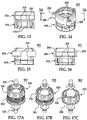
- FIGS. 14-16 illustrate a sanitary retainer 406 according to a fourth embodiment of the present invention.
- the fourth embodiment is similar to the second embodiment except that, the collet 404 and sleeve 406 are connected together by a frangible connecting member such as a plurality of frangible tabs 408.
- Plurality of frangible tabs 408 are similar to plurality of frangible tabs 308 in the third embodiment.
- a sanitary assembly 500 is shown in an unassembled configuration ( FIG. 17A ), a partially assembled configuration ( FIG. 17B ) and a fully assembled configuration ( FIG. 17C ).
- sanitary assembly 500 can include a pair of sanitary connectors 102 and a sanitary retainer 503 and a gasket (not shown).
- Sanitary retainer 503 can include a collet 504 and a sleeve 506.
- collet 504 is an essentially annular member having a through aperture 116 for receiving a gasket and terminating ends 114 of the pair of sanitary connectors 102 therein.
- Collet 504 forms a discontinuous ring at a securing end 120.
- Collet 504 also includes a receiving end 124 with resilient fingers 128 for radially contracting around terminating end 114.
- Fingers 128 are formed by narrow through slots 130 extending from receiving end 124 and terminating essentially at two thirds of the collet length. Slots 130 are shown in the Figures with rounded termination ends 130a, however, the termination ends 130a may have pointed ends or any other suitably-shaped end.
- Fingers 128 form a resilient seal by, as discussed in more detail below, forming a 360° compression around gasket 105 and terminating ends 114 of funnel formations 112 when sleeve 506 is screwed onto collet 504.
- Each finger 128 contains a stop 129, where sleeve 506 contacts collet 504 when fully assembled.
- the through slots 132 can provide resiliency to the securing end 120 of collet 104 without sacrificing durability.
- Through slots 132 are shown in the Figures with rounded termination ends 132a, however, the termination ends 132a may have pointed ends or any other suitably-shaped end.
- Threads 510 and 512 can be, for example, an Acme thread. Threads 510 and 512 can also be any other suitable thread such as a square thread, a buttress thread, a tapered thread, or a tapered pipe thread.
- Thread 510 can extend from securing end 148 of sleeve 506 to receiving end 144 of sleeve 506. Thread 512 can extend from securing end 120 of collet 504 to stop 129 of collet 504.
- sanitary retainer 503 is first placed or positioned over either one of the pair of sanitary connectors 102. As discussed previously in connection with the first embodiment, terminating ends 114 of sanitary connectors 102 can be placed into collet 504 to pre-hold sanitary connectors 102 and the gasket disposed between terminating ends 114 of sanitary connectors 102. Sleeve 506 can then be screwed onto collet 504, creating a 360° radial compression connection of sanitary connectors 102 and gasket 105.
- FIG. 22 illustrates a collet 604 according to a sixth embodiment of the present invention.
- the sixth embodiment is similar to the first embodiment except that collet 604 has a number of interlocks 608.
- Each interlock 208 includes a groove 610 for receiving a projection 612.
- each of resilient fingers 628 can include a groove 610 for receiving a projection 612 from an adjacent finger and a projection for interlocking with an adjacent finger.
- Each projection 612 is shown in the Figures as a trapezoidal shaped projection. However, projections may have pointed ends, square ends, rounded ends or any other suitably-shaped end.
- Grooves 610 will generally have the same shape as projections 612 so that as the sleeve (such as sleeve 106 of FIG.
- collet 604 moves over collet 604, interlocks 608 will hold collet 604 together. As such collet 604 will move into the sleeve when the sleeve does not contact the bottom of the collet. Accordingly, an operator does not have to turn and close the retainer containing collet 604 after the sleeve has been secured on the collet (as discussed in connection with FIGS. 1 )
Landscapes
- Engineering & Computer Science (AREA)
- General Engineering & Computer Science (AREA)
- Health & Medical Sciences (AREA)
- Mechanical Engineering (AREA)
- Heart & Thoracic Surgery (AREA)
- Life Sciences & Earth Sciences (AREA)
- Veterinary Medicine (AREA)
- Biomedical Technology (AREA)
- Surgery (AREA)
- Animal Behavior & Ethology (AREA)
- General Health & Medical Sciences (AREA)
- Public Health (AREA)
- Epidemiology (AREA)
- Molecular Biology (AREA)
- Nuclear Medicine, Radiotherapy & Molecular Imaging (AREA)
- Medical Informatics (AREA)
- Pulmonology (AREA)
- Anesthesiology (AREA)
- Hematology (AREA)
- Quick-Acting Or Multi-Walled Pipe Joints (AREA)
- Flanged Joints, Insulating Joints, And Other Joints (AREA)
- Clamps And Clips (AREA)
- Orthopedics, Nursing, And Contraception (AREA)
- Mutual Connection Of Rods And Tubes (AREA)
- Gasket Seals (AREA)
Claims (14)
- Haltevorrichtung (103) zum Verbinden eines Paars von sanitären Armaturen mit jeweils einem ersten Ende und einem zweiten Ende, wobei die zweiten Enden jeweils einen geflanschten Abschnitt haben, wobei die Haltevorrichtung (103) aufweist:ein erstes Element (104), das angepasst ist, mindestens einen Abschnitt von jedem der geflanschten Abschnitte aufzunehmen, wobei das erste Element (104) eine durchgehende Mittenöffnung (116) hat, wobei ein zweites Element (106) eine durchgehende Mittenöffnung (140) hat, die über das erste Element (104) in Eingriff bringbar ist, wobei das zweite Element (106) angepasst ist, eine Druckkraft zur dichtenden Verbindung der geflanschten Abschnitte bereitzustellen, wenn die ersten und zweiten Elemente (104, 106) sich in einer zusammengebauten Konfiguration befinden, dadurch gekennzeichnet, dass das erste Element (104) ein sicherndes Ende (120) hat, ein aufnehmendes Ende (124), eine diskontinuierliche Außenfläche, wobei die Außenfläche eine Mehrzahl von durchgehenden Schlitzen (130) definiert, die sich von dem aufnehmenden Ende (124) erstrecken und im Wesentlichen an einer ringförmigen Kante (126) abschließen, die durch den Beginn eines eingedrehten Abschnitts (122) an dem sichernden Ende (120) oder im Wesentlichen bei zwei Dritteln der Länge der ersten Elemente definiert wird, die erste und zweite gegenüberliegende Seitenkanten einer Mehrzahl von elastischen Fingern (128) definieren, und eine Mehrzahl von durchgehenden Schlitzen (132), die sich von dem sichernden Ende (120) zwischen den Seitenkanten der Mehrzahl von elastischen Fingern (128) erstrecken und annähernd an einer mittleren Sektion des zugehörigen Fingers (128) abschließen.
- Verfahren zum dichtenden Verbinden einer ersten sanitären Armatur und einer zweiten sanitären Armatur mit einer Haltevorrichtung (103) mit ersten und zweiten Elementen (104, 106) mit durchgehenden Mittenöffnungen (116, 140), wobei die ersten und zweiten sanitären Armaturen jeweils ein erstes Ende und ein zweites Ende haben, die zweiten Enden jeweils einen geflanschten Abschnitt haben, wobei das Verfahren aufweist:Einführen des ersten Endes der ersten sanitären Armatur in die Öffnung (116) des ersten Elements (104);Positionieren des geflanschten Abschnitts der ersten sanitären Armatur in dem ersten Element (104);Positionieren des geflanschten Abschnitts der zweiten sanitären Armatur in dem ersten Element (104); undEingreifen des zweiten Elements (106) über das erste Element, so dass eine Druckkraft auf die ersten und zweiten Armaturen aufgebracht wird,dadurch gekennzeichnet, dass das erste Element (104) ein sicherndes Ende (120) hat, ein aufnehmendes Ende (124), eine diskontinuierliche Außenfläche, wobei die Außenfläche eine Mehrzahl von durchgehenden Schlitzen (130) definiert, die sich von dem aufnehmenden Ende (124) erstrecken und im Wesentlichen an einer ringförmigen Kante (126) abschließen, die durch den Beginn eines eingedrehten Abschnitts (122) an dem sichernden Ende (120) oder im Wesentlichen bei zwei Dritteln der Länge der ersten Elemente definiert wird, die erste und zweite gegenüberliegende Seitenkanten einer Mehrzahl von elastischen Fingern (128) definieren, und eine Mehrzahl von durchgehenden Schlitzen (132), die sich von dem sichernden Ende (120) zwischen den Seitenkanten der Mehrzahl von elastischen Fingern (128) erstrecken und annähernd an einer mittleren Sektion des zugehörigen Fingers (128) abschließen.
- Haltevorrichtung (103) nach Anspruch 1 oder Verfahren nach Anspruch 2, wobei eine Dichtung (105) zwischen den geflanschten Abschnitten und dem Paar von sanitären Armaturen angeordnet ist.
- Haltevorrichtung (103) nach Anspruch 1 oder 3, wobei das erste Element (104) eine äußere Gewindefläche aufweist, die angepasst ist, mit einer inneren Gewindefläche des zweiten Elements (106) zusammenzupassen, wenn sie zusammengebaut sind.
- Haltevorrichtung (103) oder Verfahren nach einem der Ansprüche 1 oder 3, wobei das zweite Element (106) eine im Allgemeinen konzentrische Außenfläche hat.
- Haltevorrichtung (103) oder Verfahren nach Anspruch 5, wobei das zweite Element (106) mindestens einen Federabschnitt enthält, wobei der mindestens eine Federabschnitt von der konzentrischen Außenfläche nach außen vorsteht, um einen Bogen (212) mit einer Öffnung (214) zu bilden.
- Haltevorrichtung (103) nach Anspruch 1, wobei die ersten und zweiten Seitenkanten Verriegelungsabschnitte enthalten und wobei der Verriegelungsabschnitt von mindestens einem elastischen Finger (128) der Mehrzahl von elastischen Fingern (128) angepasst ist, den Verriegelungsabschnitt eines benachbarten elastischen Fingers (128) der Mehrzahl von elastischen Fingern (128) aufzunehmen, wenn sie zusammengebaut sind.
- Haltevorrichtung (103) nach Anspruch 1 oder 3, wobei die ersten und zweiten Elemente (104, 106) durch mindestens ein zerbrechliches Verbindungselement verbunden sind, wenn sich die ersten und zweiten Elemente (104, 106) in einer nicht zusammengebauten Konfiguration befinden.
- Haltevorrichtung (103) oder Verfahren nach einem der Ansprüche 1 bis 3, wobei das erste Element (104) ein erstes und zweites Ende hat, wobei die ersten und zweiten Enden jeweils ein Regal aufweisen, das radial nach innen davon vorsteht.
- Haltevorrichtung (103) nach Anspruch 1 oder 3, wobei die Druckkraft des zweiten Elements (106) eine 360-Grad-Kompression bereitstellt, um die geflanschten Abschnitte dichtend zu verbinden, wenn die ersten und zweiten Elemente (104, 106) sich in einer zusammengebauten Konfiguration befinden.
- Verfahren nach Anspruch 2 oder 3, wobei das erste Element (104) eine Außengewindefläche hat und das zweite Element (106) eine Innengewindefläche hat und wobei das Eingreifen des zweiten Elements (106) über das erste Element (104) umfasst:Drehen mindestens eines des ersten Elements (104) und des zweiten Elements (106), so dass die Außengewindeflächen mit der Innengewindefläche zusammenpassen.
- Verfahren nach Anspruch 2, wobei die ersten und zweiten Seitenkanten Verriegelungsabschnitte enthalten und wobei das Eingreifen des zweiten Elements (106) des ersten Elements (104) umfasst:Aufnehmen des Verriegelungsabschnitts von mindestens einem elastischen Element (128) der Mehrzahl von elastischen Elementen (128) in dem Verriegelungsabschnitt eines benachbarten elastischen Elements (128) der Mehrzahl von elastischen Elementen (128).
- Verfahren nach Anspruch 2 oder 3, wobei die ersten und zweiten Elemente (104, 106) durch mindestens ein zerbrechliches Verbindungselement verbunden sind, wenn die ersten und zweiten Elemente (104, 106) sich in einer nicht zusammengebauten Konfiguration befinden, wobei das Verfahren ferner umfasst:Brechen des mindestens einen zerbrechlichen Verbindungselements, wenn das zweite Element (106) sich über dem ersten Element (104) in Eingriff befindet.
- Kit zum Zusammenbauen eines Paares von sanitären Armaturen mit jeweils einem ersten Ende und einem zweiten Ende, wobei die zweiten Enden jeweils einen geflanschten Abschnitt aufweisen, wobei der Kit umfasst:ein erstes Element (104) mit einer durchgehenden Mittenöffnung (116), die bemessen ist, die geflanschten Abschnitte aufzunehmen, und ein zweites Element (106) mit einer im Allgemeinen konzentrischen Außenfläche und einer durchgehende Mittenöffnung (14), dadurch gekennzeichnet, dass das erste Element (104) ein sicherndes Ende (120) hat, ein aufnehmendes Ende (124), eine diskontinuierliche Außenfläche, wobei die Außenfläche eine Mehrzahl von durchgehenden Schlitzen (130) definiert, die sich von dem aufnehmenden Ende (124) erstrecken und im Wesentlichen an einer ringförmigen Kante (126) abschließen, die durch den Beginn eines eingedrehten Abschnitts (122) an dem sichernden Ende (120) oder im Wesentlichen bei zwei Dritteln der Länge der ersten Elemente definiert wird, die erste und zweite gegenüberliegende Seitenkanten einer Mehrzahl von elastischen Fingern (128) definieren, die, wenn komprimiert, die geflanschten Abschnitte einzeln verbinden, wenn die ersten und zweiten Elemente (102, 106) sich in einer zusammengebauten Konfiguration befinden, und eine Mehrzahl von durchgehenden Schlitzen (132), die sich von dem sichernden Ende (120) zwischen den Seitenkanten der Mehrzahl von elastischen Fingern (128) erstrecken und annähernd an einer mittleren Sektion des zugehörigen Fingers (128) abschließen.
Applications Claiming Priority (3)
| Application Number | Priority Date | Filing Date | Title |
|---|---|---|---|
| US16602809P | 2009-04-02 | 2009-04-02 | |
| US12/752,803 US9605782B2 (en) | 2009-04-02 | 2010-04-01 | Sanitary retainer |
| PCT/US2010/029730 WO2010115068A2 (en) | 2009-04-02 | 2010-04-02 | Sanitary retainer |
Publications (3)
| Publication Number | Publication Date |
|---|---|
| EP2414031A2 EP2414031A2 (de) | 2012-02-08 |
| EP2414031A4 EP2414031A4 (de) | 2014-03-26 |
| EP2414031B1 true EP2414031B1 (de) | 2017-09-13 |
Family
ID=42825557
Family Applications (1)
| Application Number | Title | Priority Date | Filing Date |
|---|---|---|---|
| EP10759451.7A Not-in-force EP2414031B1 (de) | 2009-04-02 | 2010-04-02 | Haltering für sanitärarmaturen |
Country Status (8)
| Country | Link |
|---|---|
| US (2) | US9605782B2 (de) |
| EP (1) | EP2414031B1 (de) |
| JP (1) | JP5925675B2 (de) |
| KR (1) | KR20110139761A (de) |
| CN (1) | CN102395402B (de) |
| CA (1) | CA2757521A1 (de) |
| MX (1) | MX2011010410A (de) |
| WO (1) | WO2010115068A2 (de) |
Families Citing this family (20)
| Publication number | Priority date | Publication date | Assignee | Title |
|---|---|---|---|---|
| US8328458B2 (en) | 2007-07-20 | 2012-12-11 | Twin Bay Medical, Inc. | Sanitary clamp |
| US20090271966A1 (en) * | 2008-04-30 | 2009-11-05 | Weatherford/Lamb, Inc. | Shear coupling assembly with backoff prevention |
| US9605782B2 (en) | 2009-04-02 | 2017-03-28 | Saint-Gobain Performance Plastics Corporation | Sanitary retainer |
| US9151424B2 (en) * | 2013-10-24 | 2015-10-06 | Caterpillar Inc. | Connector for connecting hose coupler to drain knob |
| US9671052B2 (en) | 2015-10-27 | 2017-06-06 | Whirlpool Corporation | Collet securing device for joining two fluid lines and providing lateral support at the connection of the two fluid lines |
| US10557469B2 (en) | 2016-03-22 | 2020-02-11 | Whirlpool Corporation | Multi-outlet fluid flow system for an appliance incorporating a bi-directional motor |
| DE102016015853B3 (de) | 2016-04-18 | 2023-01-12 | Sartorius Stedim Biotech Gmbh | Anschlussvorrichtung |
| DE102016107159B4 (de) | 2016-04-18 | 2021-10-07 | Sartorius Stedim Biotech Gmbh | Anschlussvorrichtung |
| DE102016108905B4 (de) | 2016-05-13 | 2021-10-07 | Sartorius Stedim Biotech Gmbh | Anschlussvorrichtung |
| CA3044698C (en) * | 2016-11-23 | 2020-01-07 | Hendrickson Usa, L.L.C. | Body bound shear connection |
| US10655266B2 (en) | 2016-11-30 | 2020-05-19 | Whirlpool Corporation | Lint processing fluid pump for a laundry appliance |
| US10662574B2 (en) | 2017-02-27 | 2020-05-26 | Whirlpool Corporation | Self cleaning heater exchanger plate |
| US10619289B2 (en) | 2017-02-27 | 2020-04-14 | Whirlpool Corporation | Self cleaning diverter valve |
| US10480117B2 (en) | 2017-02-27 | 2019-11-19 | Whirlpool Corporation | Self cleaning sump cover |
| US10634412B2 (en) | 2017-04-10 | 2020-04-28 | Whirlpool Corporation | Concealed upstream air tower guide vanes |
| US10697700B2 (en) | 2018-01-17 | 2020-06-30 | Whirlpool Corporation | Refrigeration water dispensing system |
| US11692633B2 (en) | 2021-06-04 | 2023-07-04 | Masterflex, Llc | Pinch clamp and mount |
| USD1027596S1 (en) | 2022-02-14 | 2024-05-21 | Masterflex, Llc | Pinch clamp |
| USD1083088S1 (en) | 2023-03-04 | 2025-07-08 | Carolina Components Group, Inc. | Pinch clamp |
| USD1069569S1 (en) | 2023-03-04 | 2025-04-08 | Carolina Components Group, Inc. | Pinch clamp |
Family Cites Families (132)
| Publication number | Priority date | Publication date | Assignee | Title |
|---|---|---|---|---|
| US36410A (en) * | 1862-09-09 | Hose-coupling | ||
| US850731A (en) * | 1906-07-28 | 1907-04-16 | Erick T Christensen | Pipe-coupling. |
| US919913A (en) * | 1906-11-20 | 1909-04-27 | James Acton Miller | Pipe connection. |
| US1390564A (en) * | 1920-01-24 | 1921-09-13 | Margaret R Elkin | Hose-clamp |
| US1441154A (en) * | 1922-04-17 | 1923-01-02 | Henry W Johnson | Hose clamp |
| US2466526A (en) * | 1944-04-08 | 1949-04-05 | Parker Appliance Co | Coupling for tubes |
| FR1052094A (fr) | 1952-03-05 | 1954-01-21 | Ile D Etudes D App S Et D Equi | Raccord pour tuyauteries souples |
| US2832598A (en) * | 1955-04-04 | 1958-04-29 | Strub Andrew | Shuffleboard cue |
| FR1161980A (fr) * | 1956-04-25 | 1958-09-08 | Neue Argus Gmbh | Raccord pour un tuyau souple en caoutchouc ou en matière synthétique de grand diamètre, et procédé de fixation de ce raccord sur le tuyau |
| US2868564A (en) * | 1957-11-13 | 1959-01-13 | Arras Damiano | Hose connector with axially sliding locking sleeve |
| US2958549A (en) * | 1958-07-31 | 1960-11-01 | Hildreth A Spafford | Hose clamp |
| US3325194A (en) * | 1965-02-23 | 1967-06-13 | Caterpillar Tractor Co | High pressure hydraulic hose coupling assembly |
| US3406991A (en) * | 1967-04-24 | 1968-10-22 | Midland Ross Corp | Flange and backup ring for a conduit joint |
| US3528689A (en) | 1967-12-22 | 1970-09-15 | Homer D Roe | Tube joint |
| US3568977A (en) * | 1969-01-29 | 1971-03-09 | Illinois Tool Works | Valve assembly |
| US3589752A (en) * | 1969-07-28 | 1971-06-29 | Caterpillar Tractor Co | Mechanical joined hose coupling of extruded components |
| US3653692A (en) * | 1970-02-09 | 1972-04-04 | John W Henson | Hose coupling method and means |
| US3724882A (en) | 1971-05-10 | 1973-04-03 | Ford Motor Co | Tube-to-hose connection |
| US3868130A (en) | 1971-08-16 | 1975-02-25 | Gary T Schwertner | Adjustable reusable tubing end fitting |
| US3980325A (en) * | 1973-04-12 | 1976-09-14 | Duane D. Robertson | Fitting for flexible plastic pipe |
| US3915167A (en) * | 1974-05-23 | 1975-10-28 | Atlantic Design & Dev Corp | Intravenous clamp |
| US4049301A (en) * | 1974-06-18 | 1977-09-20 | Dzus Fastener Co., Inc. | Toggle latch |
| FR2383385A1 (fr) * | 1977-03-09 | 1978-10-06 | Legris France Sa | Perfectionnement aux raccords rapides pour tuyaux flexibles renforces multicouches pour fluides |
| US4205417A (en) | 1977-09-28 | 1980-06-03 | Mackal Glenn H | Ferrule |
| JPS5744731Y2 (de) * | 1978-01-26 | 1982-10-02 | ||
| US4247076A (en) * | 1979-04-16 | 1981-01-27 | Abbott Laboratories | Toggle action tubing clamp |
| DE7920496U1 (de) * | 1979-07-18 | 1979-11-08 | Festo-Maschinenfabrik Gottlieb Stoll, 7300 Esslingen | Anschlussverbindungsstueck fuer leitungen zum fuehren von gasfoermigen oder fluessigen medien |
| US4412693A (en) * | 1981-07-31 | 1983-11-01 | Sergio Campanini | Swivel hose coupling with threaded nipple |
| US4442994A (en) * | 1982-02-02 | 1984-04-17 | Logsdon Duane D | Pipe hanger capable of totally encircling a pipe |
| US4487205A (en) * | 1982-04-26 | 1984-12-11 | Ethicon, Inc. | Non-metallic, bio-compatible hemostatic clips |
| US4487336A (en) * | 1982-06-01 | 1984-12-11 | Sneider Vincent R | Syringe closure assembly with attachable nozzle |
| FR2545187B1 (fr) * | 1983-04-27 | 1985-07-05 | Commissariat Energie Atomique | Dispositif de raccordement etanche |
| IL72279A (en) | 1983-07-19 | 1988-11-30 | Pfister Juerg | Pipe coupling device |
| GB8403370D0 (en) * | 1984-02-08 | 1984-03-14 | Lucas Ind Plc | Hydraulic fluid connector |
| US4564222A (en) * | 1984-08-27 | 1986-01-14 | Hydrasearch Co., Inc. | Separable coupling for thin-walled flexible hose |
| US4632435A (en) * | 1984-12-27 | 1986-12-30 | American Medical Systems, Inc. | Tubing connector system |
| US4588160A (en) * | 1985-03-27 | 1986-05-13 | Sherwood Medical Company | Tube clamping device |
| IT1187599B (it) * | 1985-10-22 | 1987-12-23 | Protec Pordenonese Spa | Giunto a tenuta per tubazioni flessibili di tipo perfezionato |
| DK153288C (da) * | 1985-10-30 | 1988-11-14 | Coloplast As | Slangeklemme til et udtoemningsslangestykke fra en vaeskeopsamlingspose |
| US4723948A (en) * | 1986-11-12 | 1988-02-09 | Pharmacia Nu Tech | Catheter attachment system |
| US5388870A (en) * | 1987-06-23 | 1995-02-14 | Proprietary Technology, Inc. | Apparatus for and method of attaching hoses and tubes to a fitting |
| JPH0633844B2 (ja) | 1987-09-29 | 1994-05-02 | ブリヂストンフロ−テック株式会社 | 管継手 |
| US5149145A (en) * | 1987-09-29 | 1992-09-22 | Bridgestone Flowtech Corporation | Hose fitting |
| JPH0247353Y2 (de) * | 1987-12-22 | 1990-12-12 | ||
| US4880414A (en) * | 1987-12-31 | 1989-11-14 | Pharmacia Nu Tech | Catheter attachment system |
| DE3905722A1 (de) | 1989-01-25 | 1990-07-26 | Festo Kg | Verbindungsvorrichtung |
| US4890866A (en) * | 1989-03-14 | 1990-01-02 | Mentor Corporation | Tubing connector |
| US4932689A (en) | 1989-07-28 | 1990-06-12 | Teleflex Incorporated | Hose fitting assembly |
| US4944485A (en) * | 1989-08-28 | 1990-07-31 | Ivac Corporation | Clamp for flexible tubing |
| DE3936102C1 (de) * | 1989-10-30 | 1991-01-17 | Karl Dipl.-Ing. 4040 Neuss De Weinhold | |
| US5060987A (en) * | 1990-03-14 | 1991-10-29 | Vemco Corporation | Torsion isolation fitting |
| KR950007636B1 (ko) | 1990-06-07 | 1995-07-13 | 닛타·무아 가부시키가이샤 | 관연결부 및 그 관빠짐 방지기구 |
| US5150925A (en) | 1990-09-27 | 1992-09-29 | Bridgestone Flowtech Corporation | Hose fitting |
| DE9016310U1 (de) * | 1990-11-30 | 1991-02-21 | Hewing GmbH, 4434 Ochtrup | Rohrverbindung, insbesondere an Verbundrohren |
| DE4115791C1 (de) * | 1991-05-10 | 1992-09-03 | Mannesmann Ag, 4000 Duesseldorf, De | |
| DE4117932A1 (de) | 1991-05-31 | 1992-12-03 | Beul Gmbh & Co Kg Geb | Kupplungsvorrichtung zur herstellung einer nichtloesbaren rohrverbindung |
| DE4118732A1 (de) * | 1991-06-07 | 1992-12-10 | Joka Kathetertechnik Gmbh | Schlauchklemme fuer medizinische zwecke |
| US5222555A (en) | 1991-12-13 | 1993-06-29 | Abb Vetco Gray Inc. | Emergency casing hanger system |
| CA2066979C (en) * | 1992-03-06 | 1998-08-04 | Michael A. Sweeney | Push in plastic tube fitting |
| US5240291A (en) * | 1992-07-06 | 1993-08-31 | Zornow Jeffrey S | Sanitary hose coupler |
| US5361806A (en) * | 1992-07-07 | 1994-11-08 | Titeflex Corporation | Kevlar reinforced high pressure hose assembly with grip and environmental barrier |
| US5238218A (en) * | 1992-07-15 | 1993-08-24 | Mackal Glenn H | Tube clamp |
| US5275447A (en) * | 1992-08-14 | 1994-01-04 | Misti Maid Inc. | Hose coupling |
| US5318546A (en) * | 1992-08-28 | 1994-06-07 | Bierman Steven F | Method of catheter irrigation and aspiration |
| US5271649A (en) * | 1992-12-31 | 1993-12-21 | Southco, Inc. | Over center draw latch with lock bolt action |
| JPH07111230B2 (ja) | 1993-02-19 | 1995-11-29 | ティーエイチアイシステム株式会社 | 流体配管用継手 |
| US5423581A (en) * | 1993-03-31 | 1995-06-13 | Salyers; Marshall L. | Low carryover fitting and method for coupling tubing to a device using the same |
| US5658266A (en) * | 1993-08-02 | 1997-08-19 | Colacello; Albert A. | Manual venting and cutting apparatus for ostomy pouches |
| JPH07145894A (ja) | 1993-10-01 | 1995-06-06 | Tokyo Gas Co Ltd | フレキシブル管用継手 |
| US5536258A (en) * | 1994-02-14 | 1996-07-16 | Fresenius Usa, Inc. | Antibacterial medical tubing connector |
| BR7400587U (pt) * | 1994-03-24 | 1994-10-04 | Seabra Helio Lanfranchi | Aperfeiçoamento introduzido no processo de fabricação de luva de conexão para tubos |
| US5409117A (en) * | 1994-04-13 | 1995-04-25 | Kvm Technologies, Inc. | Liquid specimen vessel |
| US5476291A (en) * | 1994-10-21 | 1995-12-19 | Winzeler Stamping Company | Hose coupling |
| JP3771958B2 (ja) * | 1994-12-15 | 2006-05-10 | ルーク ゲトリーベ−ジステーメ ゲゼルシャフト ミット ベシュレンクテル ハフツング | 円錐プーリ形巻掛け伝動装置を備えた駆動ユニット |
| US5590859A (en) * | 1995-01-23 | 1997-01-07 | Lord; Paul J. | Ratcheting pipe hanger assembly |
| US5649780A (en) * | 1995-02-06 | 1997-07-22 | Delair Group Incorporated | Collet for telescoping assembly |
| US5622393A (en) * | 1995-06-30 | 1997-04-22 | Pure Fit Incorporated | Re-usable fitting for flexible hoses |
| DE29513105U1 (de) | 1995-08-16 | 1995-10-19 | Rehau Ag + Co, 95111 Rehau | Klemmverbinder |
| US5713912A (en) * | 1995-08-30 | 1998-02-03 | Stress Management, Inc. | Ligating clip having ramp-shaped vessel clamping members and tool for applying same |
| NO305334B1 (no) * | 1996-04-01 | 1999-05-10 | Eilif Elvegaard | Klammeranordning for fastspenning av r°r e.l. |
| US6422529B1 (en) * | 1996-05-07 | 2002-07-23 | Adelberg Kenneth | Roller clamps for intravenous administration sets |
| JP2799562B2 (ja) | 1996-08-09 | 1998-09-17 | 日本ピラー工業株式会社 | 樹脂製管継手 |
| DE19639794C2 (de) | 1996-09-27 | 2001-07-26 | K Dietzel Gmbh Dipl Ing | Schlauchfassung und Verfahren zu deren Herstellung |
| US5729872A (en) * | 1996-12-06 | 1998-03-24 | Ginocchio; Mark H. | Method of storing bundled items |
| US6101684A (en) * | 1996-12-06 | 2000-08-15 | Ginocchio; Mark H. | Self-aligning handling or storing device and methods of use therefor |
| US5984378A (en) * | 1996-12-20 | 1999-11-16 | Itt Automotive, Inc. | Inline quick connector |
| US5882047A (en) * | 1996-12-20 | 1999-03-16 | Itt Automotive, Inc. | Quick connector fluid coupling |
| US5865817A (en) * | 1997-04-29 | 1999-02-02 | Moenning; Stephen P. | Apparatus and method for securing a medical instrument to a cannula of a trocar assembly |
| EP1042631A1 (de) * | 1997-12-23 | 2000-10-11 | Jae-Young Shim | Rohrverbindung mit integriertem ventil |
| US6155607A (en) * | 1998-02-17 | 2000-12-05 | Parker-Hannifin Corporation | Quick connect coupling |
| FR2776747B1 (fr) * | 1998-03-27 | 2000-06-02 | Hutchinson | Raccord encliquetable pour tuyau de transfert de fluide |
| DE19840136A1 (de) | 1998-09-03 | 2000-03-09 | Volkswagen Ag | Halterungselement und Halterung für starre Leitungen in einem Fahrzeug |
| US6010162A (en) * | 1998-09-25 | 2000-01-04 | Aeroquip Corporation | Clip fitting for a hose |
| IL127029A (en) * | 1998-11-12 | 2002-03-10 | Medivice Systems Ltd | Pinched grip |
| US6254144B1 (en) | 1998-12-02 | 2001-07-03 | Kilgore Manufacturing | Hose coupling |
| US6113062A (en) * | 1999-01-28 | 2000-09-05 | Dsu Medical Corporation | Squeeze clamp |
| IT1310919B1 (it) * | 1999-06-10 | 2002-02-27 | Enrico Balbo | Pinza a collocazione rapida per la regolazione della portata ditubazioni flessibili, in particolare per uso medicale. |
| JP3430237B2 (ja) * | 1999-07-02 | 2003-07-28 | Smc株式会社 | 管継手 |
| US6261254B1 (en) * | 1999-07-21 | 2001-07-17 | C. R. Bard, Inc. | Lever-style drain assembly for urine collection container |
| US6170887B1 (en) * | 1999-07-26 | 2001-01-09 | Armaturenfabrik Hermann Voss Gmbh + Co. | Plug connector for rapid and releaseable connection of pressurized lines |
| JP3451229B2 (ja) | 1999-11-15 | 2003-09-29 | 東尾メック株式会社 | 管継手 |
| US6390721B1 (en) * | 1999-12-18 | 2002-05-21 | Marconi Data System, Inc. | Multi-mount clamp for a structural member |
| TW457349B (en) * | 2000-01-06 | 2001-10-01 | Shen Jung Shan | Positioning and leakage proof collar |
| US6749233B2 (en) | 2000-06-08 | 2004-06-15 | Hitachi Metals, Ltd. | Sleeve-type pipe joint |
| JP3887816B2 (ja) * | 2001-01-17 | 2007-02-28 | ニプロ株式会社 | 相互連結可能な一対のカプラー |
| US6708377B2 (en) * | 2001-04-30 | 2004-03-23 | Bio Pure Technology Ltd | Tube clamp |
| US6796586B2 (en) | 2001-07-09 | 2004-09-28 | Twin Bay Medical, Inc. | Barb clamp |
| US6679529B2 (en) * | 2001-08-06 | 2004-01-20 | Theodore D. Johnson | Connection system |
| US6860521B2 (en) * | 2001-09-13 | 2005-03-01 | William H. Berg | Hose coupler |
| KR200269757Y1 (ko) | 2001-11-27 | 2002-03-25 | 주식회사 원플라텍 | 원터치식 관 연결장치 |
| US6631537B1 (en) * | 2002-04-05 | 2003-10-14 | Han-Ching Huang | Buckle device |
| WO2003089797A2 (en) * | 2002-04-16 | 2003-10-30 | Werth Albert A | Barb clamp |
| US6755445B2 (en) * | 2002-07-29 | 2004-06-29 | Thomas Industries Inc. | Fitting |
| US20040045447A1 (en) * | 2002-09-09 | 2004-03-11 | Ramon Navarro | Sanitary hose couplers |
| KR200302163Y1 (ko) | 2002-10-11 | 2003-01-30 | 성우파이프 (주) | 이중수밀유지용 관 |
| DE20221865U1 (de) | 2002-12-19 | 2008-10-02 | Parker Hannifin Gmbh | Druckfeste Flanschverbindung |
| DE10304074B3 (de) | 2003-01-31 | 2004-02-05 | A. Raymond & Cie | Lösbare Steckverbindung für Hochdruckleitungen |
| US7014216B2 (en) | 2003-04-29 | 2006-03-21 | Thc International, Llc | Joint assembly for flexible and semi-rigid pipings |
| JP4329063B2 (ja) * | 2003-05-23 | 2009-09-09 | Smc株式会社 | 管継手 |
| EP1519094B1 (de) * | 2003-09-25 | 2009-03-11 | Philmac Pty. Ltd. | Befestigungsring für eine Drehkupplung für Rohrleitungen |
| US8256802B2 (en) | 2003-10-17 | 2012-09-04 | Twin Bay Medical, Inc. | Barb clamp with collet interlocks |
| US7922212B2 (en) | 2003-10-17 | 2011-04-12 | Twin Bay Medical, Inc. | Barb clamp with smooth bore |
| US20050082826A1 (en) | 2003-10-17 | 2005-04-21 | Twin Bay Medical, Inc. | Barb clamp |
| US7922213B2 (en) | 2003-10-17 | 2011-04-12 | Twin Bay Medical, Inc. | Barb clamp with smooth bore |
| GB0402564D0 (en) | 2004-02-05 | 2004-03-10 | Maunder Roy P | Tube connector |
| US7284731B1 (en) * | 2004-03-18 | 2007-10-23 | Theodore Donald Johnson | Sanitary clamp |
| US7284137B2 (en) * | 2004-06-29 | 2007-10-16 | Intel Corporation | System and method for managing power consumption within an integrated circuit |
| US20060131465A1 (en) * | 2004-12-22 | 2006-06-22 | Lynch Edward J Jr | Pipe support and method of installation |
| WO2006101883A2 (en) * | 2005-03-16 | 2006-09-28 | Single Use Brx, Llc | Apparatus and method for mixing with a diaphragm pump |
| US20080272590A1 (en) * | 2007-05-02 | 2008-11-06 | Howard Joseph D | Reusable fitting, connector assembly and kit |
| US9605782B2 (en) | 2009-04-02 | 2017-03-28 | Saint-Gobain Performance Plastics Corporation | Sanitary retainer |
| GB0918442D0 (en) * | 2009-10-20 | 2009-12-09 | Bio Pure Technology Ltd | Tube retainer |
-
2010
- 2010-04-01 US US12/752,803 patent/US9605782B2/en not_active Expired - Fee Related
- 2010-04-02 JP JP2012503733A patent/JP5925675B2/ja not_active Expired - Fee Related
- 2010-04-02 MX MX2011010410A patent/MX2011010410A/es unknown
- 2010-04-02 CA CA2757521A patent/CA2757521A1/en not_active Abandoned
- 2010-04-02 KR KR1020117025757A patent/KR20110139761A/ko not_active Abandoned
- 2010-04-02 EP EP10759451.7A patent/EP2414031B1/de not_active Not-in-force
- 2010-04-02 WO PCT/US2010/029730 patent/WO2010115068A2/en not_active Ceased
- 2010-04-02 CN CN201080015202.3A patent/CN102395402B/zh not_active Expired - Fee Related
-
2017
- 2017-03-07 US US15/452,450 patent/US10619772B2/en not_active Expired - Fee Related
Non-Patent Citations (1)
| Title |
|---|
| None * |
Also Published As
| Publication number | Publication date |
|---|---|
| CN102395402A (zh) | 2012-03-28 |
| US20170219142A1 (en) | 2017-08-03 |
| CA2757521A1 (en) | 2010-10-07 |
| EP2414031A4 (de) | 2014-03-26 |
| US20100253075A1 (en) | 2010-10-07 |
| KR20110139761A (ko) | 2011-12-29 |
| JP5925675B2 (ja) | 2016-05-25 |
| US9605782B2 (en) | 2017-03-28 |
| WO2010115068A3 (en) | 2011-03-17 |
| CN102395402B (zh) | 2016-05-25 |
| WO2010115068A2 (en) | 2010-10-07 |
| JP2012522948A (ja) | 2012-09-27 |
| MX2011010410A (es) | 2011-10-17 |
| EP2414031A2 (de) | 2012-02-08 |
| US10619772B2 (en) | 2020-04-14 |
Similar Documents
| Publication | Publication Date | Title |
|---|---|---|
| EP2414031B1 (de) | Haltering für sanitärarmaturen | |
| US12049974B2 (en) | Tubular connector | |
| US11953124B2 (en) | Pre-assembled coupling assembly with flexible hose adapter | |
| RU2698381C1 (ru) | Муфта, имеющая фиксатор с лапками | |
| US9447906B2 (en) | Self-locking push-to-connect insert | |
| EP3249276B1 (de) | Rohrverbindungsstruktur aus harz | |
| EP3203131A1 (de) | Aus harz hergestellte rohrverbindung | |
| KR20180137583A (ko) | 탭이 형성된 리테이너 및 관찰 구멍을 가지는 피팅 | |
| CN107763349A (zh) | 快速连接器 | |
| EP4339497A1 (de) | Seitenverbinder für unterirdische rohrleitungen | |
| HK1164172A (en) | Sanitary retainer | |
| HK1219996B (en) | Fitting having receptacle of varying depth | |
| HK1219996A1 (zh) | 具有变化深度的容置部的接头 | |
| HK1260479B (en) | Fitting having tabbed retainer and observation apertures | |
| HK1260479A1 (en) | Fitting having tabbed retainer and observation apertures | |
| HK1205549B (en) | Fitting having receptacle of varying depth |
Legal Events
| Date | Code | Title | Description |
|---|---|---|---|
| PUAI | Public reference made under article 153(3) epc to a published international application that has entered the european phase |
Free format text: ORIGINAL CODE: 0009012 |
|
| 17P | Request for examination filed |
Effective date: 20110928 |
|
| AK | Designated contracting states |
Kind code of ref document: A2 Designated state(s): AT BE BG CH CY CZ DE DK EE ES FI FR GB GR HR HU IE IS IT LI LT LU LV MC MK MT NL NO PL PT RO SE SI SK SM TR |
|
| DAX | Request for extension of the european patent (deleted) | ||
| RAP1 | Party data changed (applicant data changed or rights of an application transferred) |
Owner name: SAINT-GOBAIN PERFORMANCE PLASTICS CORPORATION |
|
| A4 | Supplementary search report drawn up and despatched |
Effective date: 20140225 |
|
| RIC1 | Information provided on ipc code assigned before grant |
Ipc: A61M 39/06 20060101ALI20140219BHEP Ipc: A61M 39/16 20060101AFI20140219BHEP |
|
| RAP1 | Party data changed (applicant data changed or rights of an application transferred) |
Owner name: SAINT-GOBAIN PERFORMANCE PLASTICS CORPORATION |
|
| GRAP | Despatch of communication of intention to grant a patent |
Free format text: ORIGINAL CODE: EPIDOSNIGR1 |
|
| STAA | Information on the status of an ep patent application or granted ep patent |
Free format text: STATUS: GRANT OF PATENT IS INTENDED |
|
| RIC1 | Information provided on ipc code assigned before grant |
Ipc: F16L 23/04 20060101ALI20170302BHEP Ipc: A61M 39/10 20060101ALN20170302BHEP Ipc: A61M 39/16 20060101AFI20170302BHEP Ipc: A61M 39/06 20060101ALI20170302BHEP Ipc: F16L 37/138 20060101ALI20170302BHEP |
|
| RIC1 | Information provided on ipc code assigned before grant |
Ipc: A61M 39/16 20060101AFI20170307BHEP Ipc: F16L 37/138 20060101ALI20170307BHEP Ipc: F16L 23/04 20060101ALI20170307BHEP Ipc: A61M 39/06 20060101ALI20170307BHEP Ipc: A61M 39/10 20060101ALN20170307BHEP |
|
| RIC1 | Information provided on ipc code assigned before grant |
Ipc: A61M 39/06 20060101ALI20170310BHEP Ipc: F16L 37/138 20060101ALI20170310BHEP Ipc: A61M 39/10 20060101ALN20170310BHEP Ipc: A61M 39/16 20060101AFI20170310BHEP Ipc: F16L 23/04 20060101ALI20170310BHEP |
|
| INTG | Intention to grant announced |
Effective date: 20170405 |
|
| GRAS | Grant fee paid |
Free format text: ORIGINAL CODE: EPIDOSNIGR3 |
|
| GRAA | (expected) grant |
Free format text: ORIGINAL CODE: 0009210 |
|
| STAA | Information on the status of an ep patent application or granted ep patent |
Free format text: STATUS: THE PATENT HAS BEEN GRANTED |
|
| AK | Designated contracting states |
Kind code of ref document: B1 Designated state(s): AT BE BG CH CY CZ DE DK EE ES FI FR GB GR HR HU IE IS IT LI LT LU LV MC MK MT NL NO PL PT RO SE SI SK SM TR |
|
| REG | Reference to a national code |
Ref country code: GB Ref legal event code: FG4D |
|
| REG | Reference to a national code |
Ref country code: CH Ref legal event code: EP |
|
| REG | Reference to a national code |
Ref country code: IE Ref legal event code: FG4D |
|
| REG | Reference to a national code |
Ref country code: AT Ref legal event code: REF Ref document number: 927554 Country of ref document: AT Kind code of ref document: T Effective date: 20171015 |
|
| REG | Reference to a national code |
Ref country code: DE Ref legal event code: R096 Ref document number: 602010045225 Country of ref document: DE |
|
| REG | Reference to a national code |
Ref country code: NL Ref legal event code: MP Effective date: 20170913 |
|
| REG | Reference to a national code |
Ref country code: LT Ref legal event code: MG4D |
|
| PG25 | Lapsed in a contracting state [announced via postgrant information from national office to epo] |
Ref country code: LT Free format text: LAPSE BECAUSE OF FAILURE TO SUBMIT A TRANSLATION OF THE DESCRIPTION OR TO PAY THE FEE WITHIN THE PRESCRIBED TIME-LIMIT Effective date: 20170913 Ref country code: NO Free format text: LAPSE BECAUSE OF FAILURE TO SUBMIT A TRANSLATION OF THE DESCRIPTION OR TO PAY THE FEE WITHIN THE PRESCRIBED TIME-LIMIT Effective date: 20171213 Ref country code: FI Free format text: LAPSE BECAUSE OF FAILURE TO SUBMIT A TRANSLATION OF THE DESCRIPTION OR TO PAY THE FEE WITHIN THE PRESCRIBED TIME-LIMIT Effective date: 20170913 Ref country code: HR Free format text: LAPSE BECAUSE OF FAILURE TO SUBMIT A TRANSLATION OF THE DESCRIPTION OR TO PAY THE FEE WITHIN THE PRESCRIBED TIME-LIMIT Effective date: 20170913 Ref country code: SE Free format text: LAPSE BECAUSE OF FAILURE TO SUBMIT A TRANSLATION OF THE DESCRIPTION OR TO PAY THE FEE WITHIN THE PRESCRIBED TIME-LIMIT Effective date: 20170913 |
|
| REG | Reference to a national code |
Ref country code: AT Ref legal event code: MK05 Ref document number: 927554 Country of ref document: AT Kind code of ref document: T Effective date: 20170913 |
|
| PG25 | Lapsed in a contracting state [announced via postgrant information from national office to epo] |
Ref country code: GR Free format text: LAPSE BECAUSE OF FAILURE TO SUBMIT A TRANSLATION OF THE DESCRIPTION OR TO PAY THE FEE WITHIN THE PRESCRIBED TIME-LIMIT Effective date: 20171214 Ref country code: BG Free format text: LAPSE BECAUSE OF FAILURE TO SUBMIT A TRANSLATION OF THE DESCRIPTION OR TO PAY THE FEE WITHIN THE PRESCRIBED TIME-LIMIT Effective date: 20171213 Ref country code: LV Free format text: LAPSE BECAUSE OF FAILURE TO SUBMIT A TRANSLATION OF THE DESCRIPTION OR TO PAY THE FEE WITHIN THE PRESCRIBED TIME-LIMIT Effective date: 20170913 Ref country code: ES Free format text: LAPSE BECAUSE OF FAILURE TO SUBMIT A TRANSLATION OF THE DESCRIPTION OR TO PAY THE FEE WITHIN THE PRESCRIBED TIME-LIMIT Effective date: 20170913 |
|
| REG | Reference to a national code |
Ref country code: FR Ref legal event code: PLFP Year of fee payment: 9 |
|
| PG25 | Lapsed in a contracting state [announced via postgrant information from national office to epo] |
Ref country code: NL Free format text: LAPSE BECAUSE OF FAILURE TO SUBMIT A TRANSLATION OF THE DESCRIPTION OR TO PAY THE FEE WITHIN THE PRESCRIBED TIME-LIMIT Effective date: 20170913 |
|
| PG25 | Lapsed in a contracting state [announced via postgrant information from national office to epo] |
Ref country code: CZ Free format text: LAPSE BECAUSE OF FAILURE TO SUBMIT A TRANSLATION OF THE DESCRIPTION OR TO PAY THE FEE WITHIN THE PRESCRIBED TIME-LIMIT Effective date: 20170913 Ref country code: PL Free format text: LAPSE BECAUSE OF FAILURE TO SUBMIT A TRANSLATION OF THE DESCRIPTION OR TO PAY THE FEE WITHIN THE PRESCRIBED TIME-LIMIT Effective date: 20170913 Ref country code: RO Free format text: LAPSE BECAUSE OF FAILURE TO SUBMIT A TRANSLATION OF THE DESCRIPTION OR TO PAY THE FEE WITHIN THE PRESCRIBED TIME-LIMIT Effective date: 20170913 |
|
| PG25 | Lapsed in a contracting state [announced via postgrant information from national office to epo] |
Ref country code: AT Free format text: LAPSE BECAUSE OF FAILURE TO SUBMIT A TRANSLATION OF THE DESCRIPTION OR TO PAY THE FEE WITHIN THE PRESCRIBED TIME-LIMIT Effective date: 20170913 Ref country code: SM Free format text: LAPSE BECAUSE OF FAILURE TO SUBMIT A TRANSLATION OF THE DESCRIPTION OR TO PAY THE FEE WITHIN THE PRESCRIBED TIME-LIMIT Effective date: 20170913 Ref country code: IT Free format text: LAPSE BECAUSE OF FAILURE TO SUBMIT A TRANSLATION OF THE DESCRIPTION OR TO PAY THE FEE WITHIN THE PRESCRIBED TIME-LIMIT Effective date: 20170913 Ref country code: IS Free format text: LAPSE BECAUSE OF FAILURE TO SUBMIT A TRANSLATION OF THE DESCRIPTION OR TO PAY THE FEE WITHIN THE PRESCRIBED TIME-LIMIT Effective date: 20180113 Ref country code: SK Free format text: LAPSE BECAUSE OF FAILURE TO SUBMIT A TRANSLATION OF THE DESCRIPTION OR TO PAY THE FEE WITHIN THE PRESCRIBED TIME-LIMIT Effective date: 20170913 Ref country code: EE Free format text: LAPSE BECAUSE OF FAILURE TO SUBMIT A TRANSLATION OF THE DESCRIPTION OR TO PAY THE FEE WITHIN THE PRESCRIBED TIME-LIMIT Effective date: 20170913 |
|
| REG | Reference to a national code |
Ref country code: DE Ref legal event code: R097 Ref document number: 602010045225 Country of ref document: DE |
|
| PLBE | No opposition filed within time limit |
Free format text: ORIGINAL CODE: 0009261 |
|
| STAA | Information on the status of an ep patent application or granted ep patent |
Free format text: STATUS: NO OPPOSITION FILED WITHIN TIME LIMIT |
|
| PG25 | Lapsed in a contracting state [announced via postgrant information from national office to epo] |
Ref country code: DK Free format text: LAPSE BECAUSE OF FAILURE TO SUBMIT A TRANSLATION OF THE DESCRIPTION OR TO PAY THE FEE WITHIN THE PRESCRIBED TIME-LIMIT Effective date: 20170913 |
|
| 26N | No opposition filed |
Effective date: 20180614 |
|
| PG25 | Lapsed in a contracting state [announced via postgrant information from national office to epo] |
Ref country code: SI Free format text: LAPSE BECAUSE OF FAILURE TO SUBMIT A TRANSLATION OF THE DESCRIPTION OR TO PAY THE FEE WITHIN THE PRESCRIBED TIME-LIMIT Effective date: 20170913 Ref country code: MC Free format text: LAPSE BECAUSE OF FAILURE TO SUBMIT A TRANSLATION OF THE DESCRIPTION OR TO PAY THE FEE WITHIN THE PRESCRIBED TIME-LIMIT Effective date: 20170913 |
|
| REG | Reference to a national code |
Ref country code: CH Ref legal event code: PL |
|
| REG | Reference to a national code |
Ref country code: BE Ref legal event code: MM Effective date: 20180430 |
|
| GBPC | Gb: european patent ceased through non-payment of renewal fee |
Effective date: 20180402 |
|
| REG | Reference to a national code |
Ref country code: IE Ref legal event code: MM4A |
|
| PG25 | Lapsed in a contracting state [announced via postgrant information from national office to epo] |
Ref country code: LU Free format text: LAPSE BECAUSE OF NON-PAYMENT OF DUE FEES Effective date: 20180402 |
|
| PG25 | Lapsed in a contracting state [announced via postgrant information from national office to epo] |
Ref country code: CH Free format text: LAPSE BECAUSE OF NON-PAYMENT OF DUE FEES Effective date: 20180430 Ref country code: LI Free format text: LAPSE BECAUSE OF NON-PAYMENT OF DUE FEES Effective date: 20180430 Ref country code: BE Free format text: LAPSE BECAUSE OF NON-PAYMENT OF DUE FEES Effective date: 20180430 Ref country code: GB Free format text: LAPSE BECAUSE OF NON-PAYMENT OF DUE FEES Effective date: 20180402 |
|
| PG25 | Lapsed in a contracting state [announced via postgrant information from national office to epo] |
Ref country code: IE Free format text: LAPSE BECAUSE OF NON-PAYMENT OF DUE FEES Effective date: 20180402 |
|
| PG25 | Lapsed in a contracting state [announced via postgrant information from national office to epo] |
Ref country code: MT Free format text: LAPSE BECAUSE OF NON-PAYMENT OF DUE FEES Effective date: 20180402 |
|
| PG25 | Lapsed in a contracting state [announced via postgrant information from national office to epo] |
Ref country code: TR Free format text: LAPSE BECAUSE OF FAILURE TO SUBMIT A TRANSLATION OF THE DESCRIPTION OR TO PAY THE FEE WITHIN THE PRESCRIBED TIME-LIMIT Effective date: 20170913 |
|
| PG25 | Lapsed in a contracting state [announced via postgrant information from national office to epo] |
Ref country code: PT Free format text: LAPSE BECAUSE OF FAILURE TO SUBMIT A TRANSLATION OF THE DESCRIPTION OR TO PAY THE FEE WITHIN THE PRESCRIBED TIME-LIMIT Effective date: 20170913 Ref country code: HU Free format text: LAPSE BECAUSE OF FAILURE TO SUBMIT A TRANSLATION OF THE DESCRIPTION OR TO PAY THE FEE WITHIN THE PRESCRIBED TIME-LIMIT; INVALID AB INITIO Effective date: 20100402 |
|
| PG25 | Lapsed in a contracting state [announced via postgrant information from national office to epo] |
Ref country code: MK Free format text: LAPSE BECAUSE OF NON-PAYMENT OF DUE FEES Effective date: 20170913 Ref country code: CY Free format text: LAPSE BECAUSE OF FAILURE TO SUBMIT A TRANSLATION OF THE DESCRIPTION OR TO PAY THE FEE WITHIN THE PRESCRIBED TIME-LIMIT Effective date: 20170913 |
|
| PGFP | Annual fee paid to national office [announced via postgrant information from national office to epo] |
Ref country code: FR Payment date: 20220323 Year of fee payment: 13 |
|
| PGFP | Annual fee paid to national office [announced via postgrant information from national office to epo] |
Ref country code: DE Payment date: 20220322 Year of fee payment: 13 |
|
| REG | Reference to a national code |
Ref country code: DE Ref legal event code: R119 Ref document number: 602010045225 Country of ref document: DE |
|
| PG25 | Lapsed in a contracting state [announced via postgrant information from national office to epo] |
Ref country code: FR Free format text: LAPSE BECAUSE OF NON-PAYMENT OF DUE FEES Effective date: 20230430 Ref country code: DE Free format text: LAPSE BECAUSE OF NON-PAYMENT OF DUE FEES Effective date: 20231103 |