EP2412990B1 - Threaded joint and method of sealing a threaded joint - Google Patents
Threaded joint and method of sealing a threaded joint Download PDFInfo
- Publication number
- EP2412990B1 EP2412990B1 EP11175138.4A EP11175138A EP2412990B1 EP 2412990 B1 EP2412990 B1 EP 2412990B1 EP 11175138 A EP11175138 A EP 11175138A EP 2412990 B1 EP2412990 B1 EP 2412990B1
- Authority
- EP
- European Patent Office
- Prior art keywords
- nut
- threads
- flexible seal
- stem
- flange
- Prior art date
- Legal status (The legal status is an assumption and is not a legal conclusion. Google has not performed a legal analysis and makes no representation as to the accuracy of the status listed.)
- Active
Links
Images
Classifications
-
- F—MECHANICAL ENGINEERING; LIGHTING; HEATING; WEAPONS; BLASTING
- F16—ENGINEERING ELEMENTS AND UNITS; GENERAL MEASURES FOR PRODUCING AND MAINTAINING EFFECTIVE FUNCTIONING OF MACHINES OR INSTALLATIONS; THERMAL INSULATION IN GENERAL
- F16B—DEVICES FOR FASTENING OR SECURING CONSTRUCTIONAL ELEMENTS OR MACHINE PARTS TOGETHER, e.g. NAILS, BOLTS, CIRCLIPS, CLAMPS, CLIPS OR WEDGES; JOINTS OR JOINTING
- F16B33/00—Features common to bolt and nut
- F16B33/004—Sealing; Insulation
Definitions
- Embodiments of the subject matter disclosed herein generally relate to methods and devices for preventing a leak of fluid through a threaded joint.
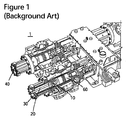
- a compressor 1 illustrated in Figure 1 which is a part, for example, of a natural gas processing installation, natural gas is compressed in a chamber 10.
- a stem 20 projects out of the chamber 10 through a flange 30.
- the stem 20 is locked to the flange 30 by a nut 40.
- a joint having components assembled using complementary threads on their contact surfaces is usually designated as a threaded joint.
- the stem 20, the flange 30 and the nut 40 which have threads partially covering their outer or inner surfaces, form a threaded joint.
- the threads on the inner surfaces of the nut 40 and the flange 30 have shapes complementary to the threads on the outer surface of the stem 20. When threads have different and complementary shapes, they are sometimes called male/female threads.
- a pressure inside the chamber 10 is higher than a pressure outside the chamber, the threaded joint is susceptible to gas leakage.
- the pressure inside the chamber 10 may increase substantially when a reciprocating piston 60 moves towards the flange 30 thereby decreasing the volume of the chamber 10.
- a seal (not shown in Figure 1 ) placed between the stem 20, the flange 30 and the nut 40 is used to prevent or limit the gas leaking outside the chamber 10.
- Extracted natural gas may contain a large proportion of hydrogen sulfide (H 2 S). Although the hydrogen sulfide is a naturally occurring substance, inhaling air with a large percentage of hydrogen sulfide is poisonous. Therefore, when processing natural gas with a large proportion of hydrogen sulfide, ensuring a good sealing of the natural gas inside the processing installation becomes important for the safety of operators. If natural gas having a large proportion of hydrogen sulfide leaks outside the gas processing installation, the operators may be poisoned while in the vicinity of the installation.
- H 2 S hydrogen sulfide
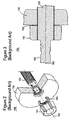
- a conventional threaded joint 100 is illustrated as an exploded view in Figure 2 .
- the threaded joint 100 includes a stem 120, a flange 130, a nut 140 and a seal 150, arranged along an axis 160, as shown in the figure.
- FIG. 3 A cross section of the threaded joint 100 as assembled is illustrated in Figure 3 .
- the stem 120 engages with the flange 130 and the nut 140.
- the seal 150 is mounted between the flange 130 and the nut 140.
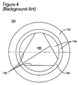
- the seal 150 of the threaded joint 100 is illustrated in Figure 4 as viewed in a plane perpendicular on the axis 160.
- the seal 150 includes an outer portion 152, which is a flat metal washer, and a rubber portion 154 attached to an internal rim of the outer portion 152.
- the rubber portion 154 includes a rubber ring 156 and three rubber flaps 158. Each of the rubber flaps 158 covers a respective area between a chord and a corresponding arch. The arches are equal and equally spaced on a circumference of the rubber ring 156.
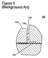
- Figure 5 is an enlarged view of a portion of Figure 3 .
- the outer portion 152 (marked only in Figure 3 for simplicity) of the seal 150 is positioned between the flange 130 and the nut 140. In this configuration, the torque that can be applied to the nut 140 is relatively low.
- the rubber flaps 158 are intended to cover the stem 120, inside the flange 130, in a portion in which the flange may have no threads.
- the rubber flaps tend to move in the same direction and may become shredded.
- a threaded joint includes a flange, a nut and a flexible seal.
- the flange has threads on an inner surface and a counter bore, the threads having shapes complementary to threads on an outer surface of a stem.
- the flange is configured to allow the stem to move by rotation through the flange.
- the nut of the exemplary embodiment has threads on an inner surface and a groove, the threads of the nut having shapes complementary to the threads on the outer surface of the stem.
- the nut is configured to move by rotation relative to the stem.
- the flexible seal of the exemplary embodiment has threads on an inner surface, the threads of the flexible seal having shapes complementary to the threads on the outer surface of the stem.
- the flexible seal is configured to move by rotation relative to the stem, and has a first portion configured to fill the counter bore in the flange, and a second portion configured to fill the groove of the nut.
- a method of sealing a threaded joint includes moving the stem having first threads on an outer surface, through the flange having second threads on an inner surface, the second threads having shapes complementary to the first threads.
- the method also includes moving a flexible seal having third threads on an inner surface, along the stem, towards the flange, until a first portion of the flexible seal fills a counter bore in the flange, the third threads having shapes complementary to the first threads.
- the method includes moving a nut having fourth threads on an inner surface, along the stem, towards the flange, until a second portion of the flexible seal fills a groove inside the nut, the fourth threads having shapes complementary to the first threads.
- the method further includes applying a predetermined torque to the nut after the second portion of the flexible seal has filled the groove inside the nut.
- a two piece sealing nut for sealing a threaded joint includes a nut and a flexible seal.
- the nut is configured to surround and move along the stem and has a groove.
- the flexible seal is configured to surround and move along the stem, inside a flange that holds the stem, and to have a first portion configured to fill a counter bore in the flange, and a second portion configured to fill the groove in the nut.
- a flexible seal includes a first portion and a second portion.
- the first portion is configured to fill a counter bore in a flange that holds a threaded stem.
- the second portion is configured to fill a groove of a nut, and has a diameter different from a diameter of the first portion.
- the first portion and the second portion have threads on a surface of an inner hole configured to allow the flexible seal to move along the threaded stem, the threads of the flexible seal having shapes complementary to threads on an outer surface of the threaded stem.
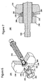
- FIG 6 is an exploded view of a threaded joint 200 according to one embodiment.
- the threaded joint 200 efficiently prevents leaking of fluids, such as natural gas.
- a stem 220 emerges from a high pressure container (see e.g., the chamber 10 in Figure 1 ) through a flange 230.
- the stem 220 has one end inside the high pressure container and an opposite end outside the high pressure container.
- the threaded joint 200 may also include a two piece sealing nut formed by a nut 240 and a flexible seal 250. All the components of the threaded joint 200 have a common axis 260.
- the flange 230, the nut 240 and the flexible seal 250 have threads on at least a portion of their respective inner surface. These threads have shapes complementary to threads on the outer surface of the stem 220.
- the nut 240 has an inside groove 270 on an end which is assembled towards the flange 230.
- the flange 230 has a counter bore 280 inside the flange, on an end which is assembled towards the nut 240.
- a diameter of the groove 270 may be larger than a diameter of the counter bore 280.
- the flexible seal 250 is configured to partially fit inside the counter bore 280 of the flange 230 and partially inside the groove 270 of the nut 240. Specifically, the flexible seal 250 has a first portion 290 shaped to fill the counter bore 280, and a second portion 300 shaped to fill the groove 270. The first portion 290 and the second portion 300 may have different diameters. In one application, the first portion 290 of the flexible seal 250 has an external diameter smaller than an external diameter of the second portion 300.
- the flexible seal 250 has a middle hole, and threads 310 located on an inner surface around the middle hole.
- the threads 310 have shapes complementary to the threads on the stem 220.
- the flexible seal 250 is configured to move along the axis 260 relative to the stem 220, when the flexible seal 250 and/or the stem 220 rotate around the axis 260.
- a cross section of the threaded joint 200 is illustrated in Figure 7 .
- the stem 220 goes through the flange 230 and the nut 240, along the axis 260.
- the flexible seal 250 is mounted between the flange 230 and the nut 240, around the stem 220.
- the flexible seal 250 fits inside the counter bore 280 of the flange 230 and the groove 270 of the nut 240.
- the flexible seal 250 may be made from a material capable to endure a substantial amount of stress before suffering permanent deformation.
- the flexible seal 250 may be made entirely of rubber or another polymer having rubber-like elasticity and compressibility.
- the material used for the flexible seal 250 may also be resistant to corrosion due to hydrogen sulfide (H 2 S).
- the nut 240 and the flexible seal 250 form a two piece sealing nut which render the threaded joint 200 capable to prevent leaking of fluids therethrough.
- the stem 220 is rotated first to move along the axis 260 through the flange 230. Then, the flexible seal 250 is rotated to advance on the stem 220 until the first portion 290 of the flexible seal 250 fills a volume of the counter bore 280 inside the flange 230.
- the first portion 290 has an external diameter smaller than a diameter of the second portion 300.
- the nut 240 is then rotated to advance on the stem 220 towards the flange 230 until the second portion 300 of the flexible seal 250 fills the groove 270 of the nut 240.
- a torque having a predetermined torque value is applied to the nut 240.
- a torque having a predetermined torque value For example, for a stem having a diameter of 2 inches, a torque of 800 foot pounds is applied, and, for a stem having a diameter of 2 1 ⁇ 2 inches, a torque of 1000 foot pounds is applied.
- the nut 240 may have an outer surface made of substantial rectangular sides, which form a hexagon in a cross-section perpendicular to the axis 260.
- the outer surface of the nut 240 is not limited to this hexagonal shape and may have other shapes.
- the nut 240 may be made of metal or other composite material considered a suitable substitute.
- the flexible seal 250 may be made of a polymer with a durometer value of about 75.
- a length of the flexible seal 250 may be chosen to enable the flexible seal support the predetermined torques.
- the length may be 0.5 inch.
- the flexible seal 250 When the torque is applied to the nut 240, the flexible seal 250 is squeezed to tightly fit around the stem 220 and inside the groove 270 and the counter bore 280.
- the presence of the groove 270 and the counter bore 280 advantageously prevents a deformation of the flexible seal 250 between external faces of nut 240 and the flange 230.
- the two piece nut sealing threaded joint formed by the nut 240 and the flexible seal 250 has an enhanced ability to prevent leaking of fluid therethrough.
- the threads 310 and the characteristics material used for the flexible seal 250 render the two piece threaded nut less prone to damage by shredding when the stem 220 rotates moving along the axis 260.
- the geometry of the components of a threaded joint has at least some of the following features: (a) a nut with a groove; (b) a flange having a counter bore; (c) a flexible seal having a first portion fitting in the groove of the nut, and a second portion fitting in a counter bore of the flange; and (d) an inner surface of the flexible seal with threads.
- These features separately or in combination lead to a threaded joint that is better than existing threaded joints in preventing leaking therethrough.
- the dimensions of the counter bore, the groove and the flexible seal are selected to allow a high enough torque to be applied to the nut. Choosing a material having appropriate characteristics for the flexible seal delays or prevents shredding. Also, by not having the flexible seal 250 exposed to the external faces of the flange 230 and the nut 240, the torque applied to the nut 240 and the flange 230 may damage less the flexible seal 250.
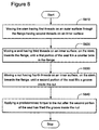
- Figure 8 illustrates a flow diagram of a method of sealing a threaded joint according to an embodiment.
- the method includes moving the stem (e.g., 220) having first threads on an outer surface, through the flange (e.g., 230) having second threads on an inner surface.
- the second threads have shapes complementary to the first threads.
- the method includes moving a flexible seal (e.g., 250) having third threads on an inner surface, on the stem (e.g., 220), towards the flange (e.g., 230), until a first portion (e.g., 290) of the flexible seal (e.g., 250) fills a counter bore (e.g., 280) in the flange (e.g., 230).
- the third threads have shapes complementary to the first threads.
- the method includes moving a nut (e.g., 240) fourth threads on an inner surface, on the stem (e.g.,220), towards the flange (e.g.,230), until a second portion (e.g.,300) of the flexible seal (e.g.,250) fills a groove (e.g.,270) inside the nut (e.g., 240).
- the fourth threads have shapes complementary to the first threads.
- the method includes applying a predetermined torque to the nut (e.g., 240) after the second portion (e.g., 300) of the flexible seal (e.g., 250) has filled the groove (e.g., 270) inside the nut (e.g., 240).
- the disclosed exemplary embodiments provide a method of sealing a threaded joint, a threaded joint and a flexible seal with a longer life cycle and preventing better leaks than the conventional methods, threaded joints and flexible seals. It should be understood that this description is not intended to limit the invention. On the contrary, the exemplary embodiments are intended to cover alternatives, modifications and equivalents, which are included in the spirit and scope of the invention as defined by the appended claims. Further, in the detailed description of the exemplary embodiments, numerous specific details are set forth in order to provide a comprehensive understanding of the claimed invention. However, one skilled in the art would understand that various embodiments may be practiced without such specific details.
Landscapes
- Engineering & Computer Science (AREA)
- General Engineering & Computer Science (AREA)
- Mechanical Engineering (AREA)
- Gasket Seals (AREA)
- Pressure Vessels And Lids Thereof (AREA)
Applications Claiming Priority (1)
| Application Number | Priority Date | Filing Date | Title |
|---|---|---|---|
| US12/847,254 US8523503B2 (en) | 2010-07-30 | 2010-07-30 | Threaded joint and method of sealing a threaded joint |
Publications (3)
| Publication Number | Publication Date |
|---|---|
| EP2412990A2 EP2412990A2 (en) | 2012-02-01 |
| EP2412990A3 EP2412990A3 (en) | 2013-03-20 |
| EP2412990B1 true EP2412990B1 (en) | 2016-09-14 |
Family
ID=44532633
Family Applications (1)
| Application Number | Title | Priority Date | Filing Date |
|---|---|---|---|
| EP11175138.4A Active EP2412990B1 (en) | 2010-07-30 | 2011-07-25 | Threaded joint and method of sealing a threaded joint |
Country Status (6)
| Country | Link |
|---|---|
| US (1) | US8523503B2 (enExample) |
| EP (1) | EP2412990B1 (enExample) |
| JP (1) | JP2012031994A (enExample) |
| CN (1) | CN102345661B (enExample) |
| CA (1) | CA2746299C (enExample) |
| RU (1) | RU2564176C2 (enExample) |
Families Citing this family (9)
| Publication number | Priority date | Publication date | Assignee | Title |
|---|---|---|---|---|
| US20140115868A1 (en) * | 2012-10-29 | 2014-05-01 | Gregory Ruhlander | Coupling System to Reduce Vibration |
| CN103527607A (zh) * | 2013-10-24 | 2014-01-22 | 昆山市联昆热压板有限公司 | 一种螺母 |
| US10433190B2 (en) * | 2014-08-05 | 2019-10-01 | Nokia Solutions And Networks Oy | Signaling physical cell identifier problems |
| US20160208840A1 (en) * | 2015-01-16 | 2016-07-21 | Matthew Neber | Fastener With Removable Head End |
| CN109424803A (zh) * | 2017-08-31 | 2019-03-05 | 杭州三花研究院有限公司 | 管路接头组件及热泵系统 |
| DE202018106798U1 (de) * | 2018-11-29 | 2020-03-04 | Conta-Clip Verbindungstechnik Gmbh | Kabelverschraubung |
| FR3089579B1 (fr) * | 2018-12-07 | 2021-07-09 | Addup | Ecrou a fente pour appareil de fabrication additive selective |
| CN110846861A (zh) * | 2019-11-14 | 2020-02-28 | 宁国双宁机械有限公司 | 一种洗衣机滚筒用脱水轴总成 |
| CN113847486A (zh) * | 2021-09-30 | 2021-12-28 | 中国船舶重工集团公司第七二四研究所 | 一种防渗防振动松脱的管路连接结构 |
Family Cites Families (42)
| Publication number | Priority date | Publication date | Assignee | Title |
|---|---|---|---|---|
| US3123245A (en) * | 1964-03-03 | Dumpis | ||
| US652530A (en) * | 1899-09-19 | 1900-06-26 | George B Wix | Nut-lock. |
| US646898A (en) * | 1900-01-17 | 1900-04-03 | Edward L Bill | Nut-lock. |
| US659215A (en) * | 1900-07-02 | 1900-10-09 | John L Doelp | Nut-lock. |
| US1607273A (en) * | 1923-12-21 | 1926-11-16 | French & Hecht | Means for the attachment of parts or members to each other |
| US1607274A (en) * | 1924-10-10 | 1926-11-16 | Firm Of French & Hecht | Means for attaching parts or members together |
| US2333388A (en) * | 1942-03-13 | 1943-11-02 | Illinois Tool Works | Fastener device |
| US2360531A (en) | 1942-10-09 | 1944-10-17 | Vincent L Kruszynski | Lock nut |
| US2360631A (en) * | 1942-12-09 | 1944-10-17 | Standard Oil Dev Co | Lubricant |
| US2502642A (en) | 1945-10-27 | 1950-04-04 | Currlin Bernard | Lock nut |
| US3259404A (en) | 1963-10-23 | 1966-07-05 | Parker Hannifin Corp | Sealed joint and gasket therefor |
| US3181899A (en) * | 1964-01-27 | 1965-05-04 | Corning Glass Works | Assembly for connecting pipe to an apertured tank |
| US3399589A (en) * | 1965-12-29 | 1968-09-03 | Lamson & Sessions Co | Sealing fastener |
| GB1172885A (en) * | 1966-05-20 | 1969-12-03 | Wirth Alfred & Co Kg | Improvements relating to Pumps |
| US3596931A (en) | 1969-02-10 | 1971-08-03 | Armor Cote Corp | Seal for lined pipe |
| GB1347783A (en) | 1971-06-25 | 1974-02-27 | Refac Technology Dev Corp | Fastening devices |
| SE363384B (enExample) * | 1972-06-29 | 1974-01-14 | Aby Ab | |
| JPS52123275U (enExample) * | 1976-03-16 | 1977-09-19 | ||
| US4046052A (en) * | 1976-10-14 | 1977-09-06 | Solitron Devices, Inc. | Torque limiting RF connector |
| US4316836A (en) * | 1980-04-23 | 1982-02-23 | E. I. Du Pont De Nemours And Company | Stabilized fluoroelastomer compositions |
| US4489963A (en) | 1982-04-13 | 1984-12-25 | Otis Engineering Corporation | Pipe joint |
| US4458925A (en) | 1983-05-19 | 1984-07-10 | Otis Engineering Corporation | Pipe joint |
| JPS6047915U (ja) * | 1983-09-09 | 1985-04-04 | 自動車機器株式会社 | 密封螺締装置 |
| US4696498A (en) | 1986-10-29 | 1987-09-29 | Quanex Corporation | Tubular connection |
| US5011162A (en) * | 1989-07-20 | 1991-04-30 | Parker Hannifin Corporation | Bi-lobed sealing element and retainer |
| FR2657938B1 (fr) * | 1990-02-05 | 1992-05-15 | Simmonds Sa | Raccord etanche perfectionne pour conduites de transport de fluides quelconques. |
| US5083821A (en) | 1990-12-05 | 1992-01-28 | Itt Corporation | Extreme temperature thread sealing method and apparatus |
| US5513859A (en) * | 1992-11-12 | 1996-05-07 | Avl Medical Instruments Ag | Sealing element |
| US5628517A (en) | 1993-06-01 | 1997-05-13 | Florida Atlantic University | Contracting/expanding self-sealing cryogenic tube seals |
| US5409337A (en) * | 1993-09-02 | 1995-04-25 | Eaton Corporation | Retained seal assembly |
| US5405176A (en) | 1994-02-15 | 1995-04-11 | Mcdonnell Douglas Corporation | High pressure mechanical seal |
| US5692865A (en) * | 1996-06-14 | 1997-12-02 | Textron Inc. | Quick release fastener system |
| US6098727A (en) | 1998-03-05 | 2000-08-08 | Halliburton Energy Services, Inc. | Electrically insulating gap subassembly for downhole electromagnetic transmission |
| US6254104B1 (en) * | 1999-04-27 | 2001-07-03 | Precision Valve Corporation | Gasket for an aerosol valve stem |
| ATE360171T1 (de) * | 1999-09-13 | 2007-05-15 | Swagelok Co | Rohrverbindung mit anzeigevorrichtung |
| US6811189B1 (en) | 2000-10-04 | 2004-11-02 | Grant Prideco, L.P. | Corrosion seal for threaded connections |
| US6866305B2 (en) | 2002-07-03 | 2005-03-15 | Spears Manufacturing Co. | Pipe fitting having strengthened starter threads |
| US6883807B2 (en) * | 2002-09-13 | 2005-04-26 | Seimens Westinghouse Power Corporation | Multidirectional turbine shim seal |
| US7628429B2 (en) | 2005-09-02 | 2009-12-08 | Watts Regulator Co. | Double containment pressure termination fitting for dissimilar materials |
| EP1760381A1 (de) | 2005-09-06 | 2007-03-07 | Siemens Aktiengesellschaft | Stutzenverschraubung sowie Stutzen und Axialdichtung für eine solche Stutzenverschraubung und Verwendung einer Stutzenverschraubung |
| RU2325581C2 (ru) * | 2006-02-03 | 2008-05-27 | Зао "Нпп Тормо" | Герметичное разъемное соединение для трубопроводов |
| US7946440B2 (en) | 2007-11-13 | 2011-05-24 | Kvt Koenig, Llc | Two-piece expandable sealing plug |
-
2010
- 2010-07-30 US US12/847,254 patent/US8523503B2/en active Active
-
2011
- 2011-07-14 CA CA2746299A patent/CA2746299C/en active Active
- 2011-07-22 JP JP2011160399A patent/JP2012031994A/ja active Pending
- 2011-07-25 EP EP11175138.4A patent/EP2412990B1/en active Active
- 2011-07-28 RU RU2011131503/06A patent/RU2564176C2/ru active
- 2011-07-29 CN CN201110224463.2A patent/CN102345661B/zh active Active
Also Published As
| Publication number | Publication date |
|---|---|
| CA2746299A1 (en) | 2012-01-30 |
| EP2412990A3 (en) | 2013-03-20 |
| EP2412990A2 (en) | 2012-02-01 |
| US8523503B2 (en) | 2013-09-03 |
| JP2012031994A (ja) | 2012-02-16 |
| CA2746299C (en) | 2019-01-15 |
| CN102345661A (zh) | 2012-02-08 |
| RU2011131503A (ru) | 2013-02-10 |
| CN102345661B (zh) | 2016-12-07 |
| US20120027539A1 (en) | 2012-02-02 |
| RU2564176C2 (ru) | 2015-09-27 |
Similar Documents
| Publication | Publication Date | Title |
|---|---|---|
| EP2412990B1 (en) | Threaded joint and method of sealing a threaded joint | |
| JP6495243B2 (ja) | バタフライバルブのシール構造 | |
| TWM453066U (zh) | 閥的填料總成 | |
| KR101241998B1 (ko) | 버터플라이 밸브 | |
| CN209340496U (zh) | 自密封垫片 | |
| CN206530768U (zh) | 一种真空阀门填料函密封结构 | |
| CN206830860U (zh) | 一种密封可靠的球阀 | |
| CN209325029U (zh) | 流体压力设备用密封柱塞及使用其的密封构造 | |
| CN208565790U (zh) | 阀门及其密封组件 | |
| CN207420524U (zh) | 一种剖分式密封圈 | |
| JP5719529B2 (ja) | ユニオン継手およびユニオン継手のシール構造 | |
| CN210623867U (zh) | 一种污水处理用管道密封结构 | |
| EP2472159A1 (en) | Flange seal | |
| CN103671935A (zh) | 多重密封结构氯气输送管道专用阀 | |
| CN201902595U (zh) | 流体球阀 | |
| RU2418231C1 (ru) | Эластичная оболочка для герметичного перекрытия трубопровода | |
| CN108397556B (zh) | 一种阀体机构 | |
| CN202746644U (zh) | 球阀 | |
| CN207161751U (zh) | 一种多重密封的可调式旋塞阀 | |
| JP3177409U (ja) | チューブ用漏れ止め構造 | |
| CN103574088A (zh) | 球阀 | |
| CN206600518U (zh) | 一种新密封结构的截止阀 | |
| CN106917911A (zh) | 一种新密封结构的截止阀 | |
| CN204512717U (zh) | 一种广范围柔性管道连接器 | |
| CN209943576U (zh) | 一种带防火结构的软密封球阀 |
Legal Events
| Date | Code | Title | Description |
|---|---|---|---|
| AK | Designated contracting states |
Kind code of ref document: A2 Designated state(s): AL AT BE BG CH CY CZ DE DK EE ES FI FR GB GR HR HU IE IS IT LI LT LU LV MC MK MT NL NO PL PT RO RS SE SI SK SM TR |
|
| AX | Request for extension of the european patent |
Extension state: BA ME |
|
| PUAI | Public reference made under article 153(3) epc to a published international application that has entered the european phase |
Free format text: ORIGINAL CODE: 0009012 |
|
| PUAL | Search report despatched |
Free format text: ORIGINAL CODE: 0009013 |
|
| AK | Designated contracting states |
Kind code of ref document: A3 Designated state(s): AL AT BE BG CH CY CZ DE DK EE ES FI FR GB GR HR HU IE IS IT LI LT LU LV MC MK MT NL NO PL PT RO RS SE SI SK SM TR |
|
| AX | Request for extension of the european patent |
Extension state: BA ME |
|
| RIC1 | Information provided on ipc code assigned before grant |
Ipc: F16B 33/00 20060101AFI20130211BHEP |
|
| 17P | Request for examination filed |
Effective date: 20130920 |
|
| RBV | Designated contracting states (corrected) |
Designated state(s): AL AT BE BG CH CY CZ DE DK EE ES FI FR GB GR HR HU IE IS IT LI LT LU LV MC MK MT NL NO PL PT RO RS SE SI SK SM TR |
|
| 17Q | First examination report despatched |
Effective date: 20150910 |
|
| GRAP | Despatch of communication of intention to grant a patent |
Free format text: ORIGINAL CODE: EPIDOSNIGR1 |
|
| INTG | Intention to grant announced |
Effective date: 20160429 |
|
| GRAS | Grant fee paid |
Free format text: ORIGINAL CODE: EPIDOSNIGR3 |
|
| GRAA | (expected) grant |
Free format text: ORIGINAL CODE: 0009210 |
|
| AK | Designated contracting states |
Kind code of ref document: B1 Designated state(s): AL AT BE BG CH CY CZ DE DK EE ES FI FR GB GR HR HU IE IS IT LI LT LU LV MC MK MT NL NO PL PT RO RS SE SI SK SM TR |
|
| REG | Reference to a national code |
Ref country code: GB Ref legal event code: FG4D |
|
| REG | Reference to a national code |
Ref country code: CH Ref legal event code: EP |
|
| REG | Reference to a national code |
Ref country code: IE Ref legal event code: FG4D |
|
| REG | Reference to a national code |
Ref country code: AT Ref legal event code: REF Ref document number: 829340 Country of ref document: AT Kind code of ref document: T Effective date: 20161015 |
|
| REG | Reference to a national code |
Ref country code: DE Ref legal event code: R096 Ref document number: 602011030300 Country of ref document: DE |
|
| REG | Reference to a national code |
Ref country code: NL Ref legal event code: FP |
|
| REG | Reference to a national code |
Ref country code: LT Ref legal event code: MG4D |
|
| PG25 | Lapsed in a contracting state [announced via postgrant information from national office to epo] |
Ref country code: RS Free format text: LAPSE BECAUSE OF FAILURE TO SUBMIT A TRANSLATION OF THE DESCRIPTION OR TO PAY THE FEE WITHIN THE PRESCRIBED TIME-LIMIT Effective date: 20160914 Ref country code: NO Free format text: LAPSE BECAUSE OF FAILURE TO SUBMIT A TRANSLATION OF THE DESCRIPTION OR TO PAY THE FEE WITHIN THE PRESCRIBED TIME-LIMIT Effective date: 20161214 Ref country code: LT Free format text: LAPSE BECAUSE OF FAILURE TO SUBMIT A TRANSLATION OF THE DESCRIPTION OR TO PAY THE FEE WITHIN THE PRESCRIBED TIME-LIMIT Effective date: 20160914 Ref country code: HR Free format text: LAPSE BECAUSE OF FAILURE TO SUBMIT A TRANSLATION OF THE DESCRIPTION OR TO PAY THE FEE WITHIN THE PRESCRIBED TIME-LIMIT Effective date: 20160914 Ref country code: FI Free format text: LAPSE BECAUSE OF FAILURE TO SUBMIT A TRANSLATION OF THE DESCRIPTION OR TO PAY THE FEE WITHIN THE PRESCRIBED TIME-LIMIT Effective date: 20160914 |
|
| REG | Reference to a national code |
Ref country code: AT Ref legal event code: MK05 Ref document number: 829340 Country of ref document: AT Kind code of ref document: T Effective date: 20160914 |
|
| PG25 | Lapsed in a contracting state [announced via postgrant information from national office to epo] |
Ref country code: LV Free format text: LAPSE BECAUSE OF FAILURE TO SUBMIT A TRANSLATION OF THE DESCRIPTION OR TO PAY THE FEE WITHIN THE PRESCRIBED TIME-LIMIT Effective date: 20160914 Ref country code: SE Free format text: LAPSE BECAUSE OF FAILURE TO SUBMIT A TRANSLATION OF THE DESCRIPTION OR TO PAY THE FEE WITHIN THE PRESCRIBED TIME-LIMIT Effective date: 20160914 Ref country code: GR Free format text: LAPSE BECAUSE OF FAILURE TO SUBMIT A TRANSLATION OF THE DESCRIPTION OR TO PAY THE FEE WITHIN THE PRESCRIBED TIME-LIMIT Effective date: 20161215 |
|
| PG25 | Lapsed in a contracting state [announced via postgrant information from national office to epo] |
Ref country code: EE Free format text: LAPSE BECAUSE OF FAILURE TO SUBMIT A TRANSLATION OF THE DESCRIPTION OR TO PAY THE FEE WITHIN THE PRESCRIBED TIME-LIMIT Effective date: 20160914 Ref country code: RO Free format text: LAPSE BECAUSE OF FAILURE TO SUBMIT A TRANSLATION OF THE DESCRIPTION OR TO PAY THE FEE WITHIN THE PRESCRIBED TIME-LIMIT Effective date: 20160914 |
|
| PG25 | Lapsed in a contracting state [announced via postgrant information from national office to epo] |
Ref country code: ES Free format text: LAPSE BECAUSE OF FAILURE TO SUBMIT A TRANSLATION OF THE DESCRIPTION OR TO PAY THE FEE WITHIN THE PRESCRIBED TIME-LIMIT Effective date: 20160914 Ref country code: CZ Free format text: LAPSE BECAUSE OF FAILURE TO SUBMIT A TRANSLATION OF THE DESCRIPTION OR TO PAY THE FEE WITHIN THE PRESCRIBED TIME-LIMIT Effective date: 20160914 Ref country code: PL Free format text: LAPSE BECAUSE OF FAILURE TO SUBMIT A TRANSLATION OF THE DESCRIPTION OR TO PAY THE FEE WITHIN THE PRESCRIBED TIME-LIMIT Effective date: 20160914 Ref country code: IS Free format text: LAPSE BECAUSE OF FAILURE TO SUBMIT A TRANSLATION OF THE DESCRIPTION OR TO PAY THE FEE WITHIN THE PRESCRIBED TIME-LIMIT Effective date: 20170114 Ref country code: AT Free format text: LAPSE BECAUSE OF FAILURE TO SUBMIT A TRANSLATION OF THE DESCRIPTION OR TO PAY THE FEE WITHIN THE PRESCRIBED TIME-LIMIT Effective date: 20160914 Ref country code: BG Free format text: LAPSE BECAUSE OF FAILURE TO SUBMIT A TRANSLATION OF THE DESCRIPTION OR TO PAY THE FEE WITHIN THE PRESCRIBED TIME-LIMIT Effective date: 20161214 Ref country code: PT Free format text: LAPSE BECAUSE OF FAILURE TO SUBMIT A TRANSLATION OF THE DESCRIPTION OR TO PAY THE FEE WITHIN THE PRESCRIBED TIME-LIMIT Effective date: 20170116 Ref country code: SM Free format text: LAPSE BECAUSE OF FAILURE TO SUBMIT A TRANSLATION OF THE DESCRIPTION OR TO PAY THE FEE WITHIN THE PRESCRIBED TIME-LIMIT Effective date: 20160914 Ref country code: SK Free format text: LAPSE BECAUSE OF FAILURE TO SUBMIT A TRANSLATION OF THE DESCRIPTION OR TO PAY THE FEE WITHIN THE PRESCRIBED TIME-LIMIT Effective date: 20160914 |
|
| REG | Reference to a national code |
Ref country code: DE Ref legal event code: R097 Ref document number: 602011030300 Country of ref document: DE |
|
| PLBE | No opposition filed within time limit |
Free format text: ORIGINAL CODE: 0009261 |
|
| STAA | Information on the status of an ep patent application or granted ep patent |
Free format text: STATUS: NO OPPOSITION FILED WITHIN TIME LIMIT |
|
| PG25 | Lapsed in a contracting state [announced via postgrant information from national office to epo] |
Ref country code: DK Free format text: LAPSE BECAUSE OF FAILURE TO SUBMIT A TRANSLATION OF THE DESCRIPTION OR TO PAY THE FEE WITHIN THE PRESCRIBED TIME-LIMIT Effective date: 20160914 |
|
| 26N | No opposition filed |
Effective date: 20170615 |
|
| PG25 | Lapsed in a contracting state [announced via postgrant information from national office to epo] |
Ref country code: SI Free format text: LAPSE BECAUSE OF FAILURE TO SUBMIT A TRANSLATION OF THE DESCRIPTION OR TO PAY THE FEE WITHIN THE PRESCRIBED TIME-LIMIT Effective date: 20160914 |
|
| REG | Reference to a national code |
Ref country code: IE Ref legal event code: MM4A |
|
| REG | Reference to a national code |
Ref country code: FR Ref legal event code: ST Effective date: 20180330 |
|
| PG25 | Lapsed in a contracting state [announced via postgrant information from national office to epo] |
Ref country code: IE Free format text: LAPSE BECAUSE OF NON-PAYMENT OF DUE FEES Effective date: 20170725 |
|
| PG25 | Lapsed in a contracting state [announced via postgrant information from national office to epo] |
Ref country code: FR Free format text: LAPSE BECAUSE OF NON-PAYMENT OF DUE FEES Effective date: 20170731 |
|
| PG25 | Lapsed in a contracting state [announced via postgrant information from national office to epo] |
Ref country code: LU Free format text: LAPSE BECAUSE OF NON-PAYMENT OF DUE FEES Effective date: 20170725 |
|
| PG25 | Lapsed in a contracting state [announced via postgrant information from national office to epo] |
Ref country code: MT Free format text: LAPSE BECAUSE OF NON-PAYMENT OF DUE FEES Effective date: 20170725 |
|
| PG25 | Lapsed in a contracting state [announced via postgrant information from national office to epo] |
Ref country code: AL Free format text: LAPSE BECAUSE OF FAILURE TO SUBMIT A TRANSLATION OF THE DESCRIPTION OR TO PAY THE FEE WITHIN THE PRESCRIBED TIME-LIMIT Effective date: 20160914 |
|
| PG25 | Lapsed in a contracting state [announced via postgrant information from national office to epo] |
Ref country code: HU Free format text: LAPSE BECAUSE OF FAILURE TO SUBMIT A TRANSLATION OF THE DESCRIPTION OR TO PAY THE FEE WITHIN THE PRESCRIBED TIME-LIMIT; INVALID AB INITIO Effective date: 20110725 Ref country code: MC Free format text: LAPSE BECAUSE OF FAILURE TO SUBMIT A TRANSLATION OF THE DESCRIPTION OR TO PAY THE FEE WITHIN THE PRESCRIBED TIME-LIMIT Effective date: 20160914 |
|
| PG25 | Lapsed in a contracting state [announced via postgrant information from national office to epo] |
Ref country code: CY Free format text: LAPSE BECAUSE OF NON-PAYMENT OF DUE FEES Effective date: 20160914 |
|
| PG25 | Lapsed in a contracting state [announced via postgrant information from national office to epo] |
Ref country code: MK Free format text: LAPSE BECAUSE OF FAILURE TO SUBMIT A TRANSLATION OF THE DESCRIPTION OR TO PAY THE FEE WITHIN THE PRESCRIBED TIME-LIMIT Effective date: 20160914 |
|
| PG25 | Lapsed in a contracting state [announced via postgrant information from national office to epo] |
Ref country code: TR Free format text: LAPSE BECAUSE OF FAILURE TO SUBMIT A TRANSLATION OF THE DESCRIPTION OR TO PAY THE FEE WITHIN THE PRESCRIBED TIME-LIMIT Effective date: 20160914 |
|
| PGFP | Annual fee paid to national office [announced via postgrant information from national office to epo] |
Ref country code: GB Payment date: 20250619 Year of fee payment: 15 |
|
| PGFP | Annual fee paid to national office [announced via postgrant information from national office to epo] |
Ref country code: NL Payment date: 20250620 Year of fee payment: 15 Ref country code: BE Payment date: 20250619 Year of fee payment: 15 |
|
| PGFP | Annual fee paid to national office [announced via postgrant information from national office to epo] |
Ref country code: DE Payment date: 20250620 Year of fee payment: 15 |
|
| PGFP | Annual fee paid to national office [announced via postgrant information from national office to epo] |
Ref country code: IT Payment date: 20250619 Year of fee payment: 15 |
|
| PGFP | Annual fee paid to national office [announced via postgrant information from national office to epo] |
Ref country code: CH Payment date: 20250801 Year of fee payment: 15 |