EP2412490A1 - Befestigungsvorrichtung - Google Patents
Befestigungsvorrichtung Download PDFInfo
- Publication number
- EP2412490A1 EP2412490A1 EP11173179A EP11173179A EP2412490A1 EP 2412490 A1 EP2412490 A1 EP 2412490A1 EP 11173179 A EP11173179 A EP 11173179A EP 11173179 A EP11173179 A EP 11173179A EP 2412490 A1 EP2412490 A1 EP 2412490A1
- Authority
- EP
- European Patent Office
- Prior art keywords
- stop element
- fastening device
- spring
- stop
- guide
- Prior art date
- Legal status (The legal status is an assumption and is not a legal conclusion. Google has not performed a legal analysis and makes no representation as to the accuracy of the status listed.)
- Granted
Links
Images

Classifications
-
- B—PERFORMING OPERATIONS; TRANSPORTING
- B25—HAND TOOLS; PORTABLE POWER-DRIVEN TOOLS; MANIPULATORS
- B25H—WORKSHOP EQUIPMENT, e.g. FOR MARKING-OUT WORK; STORAGE MEANS FOR WORKSHOPS
- B25H1/00—Work benches; Portable stands or supports for positioning portable tools or work to be operated on thereby
- B25H1/0021—Stands, supports or guiding devices for positioning portable tools or for securing them to the work
- B25H1/0078—Guiding devices for hand tools
Definitions
- the invention relates to a fastening device for a stop element of an electric hand tool, in particular a circular saw, with a guide into which the stop element can be inserted and moved along the same, and a locking device which can lock the stop element in the direction of displacement.
- a hand tool for example to be able to perform with a circular saw a possible straight and running parallel to an edge section
- these tools have a parallel guide with a stop element, which at a leading edge, for example, an edge of the workpiece to be machined, and can be guided along this.
- a stop element By such a stop element, the angle and the distance to a leading edge are preferably adjusted continuously.
- a fastening device for such a stop element is provided, which allows a stable fixation of the stop element on the hand tool.
- Previously used fastening devices for such a stop element have a guide into which a rail-like stop element can be inserted and moved along this guide.
- a screw is provided which presses the rail against the guide and thus clamped between the screw and guide.
- the fixation with a screw but has the disadvantage that in case of poor maintenance, pollution or excessive tightening forces loosening the screw and thus the fastening device is difficult. This problem is compounded by the often small dimensions of the screw head, which requires a high manual force to grasp and unscrew the screw. In extreme cases, loosening the screw without tools is not possible. Furthermore, the screws are easily lost.
- the object of the invention is to provide a fastening device of the type mentioned above, which allows a fast, tool-free adjustment of the stop element with low operating forces.
- the locking device comprises a spring element which preferably clamps the stop element in a locking position with a directed against the stopper clamping force and in a release position allows a displacement of the stop element.
- the locking is thus not by a screw, but by a spring element which clamps the stop element in a locking position.
- the spring element is moved against the spring force in the release position, whereby the locking of the stop element is released.
- the spring element is released, so that it automatically returns to the locked position.
- a quick locking of the stop element is possible, so that the risk that the stop element is moved again after setting the correct position, is reduced.
- a tool-free adjustment of the stop element is given.
- the clamping force is preferably aligned substantially perpendicular to the direction of displacement of the stop element, so that no adjustment of the position of the stop element can be effected by the spring element.
- the spring element has a recess through which the stop element extends. That is, the stopper member is guided by the spring member. As a result, on the one hand, the stop element is guided safely. On the other hand, slipping of the stop element is reliably excluded from the spring element.
- the clamping of the stop element is achieved for example by tilting the spring element in the locking position relative to the stop element. That is, in the release position, the stop element can be moved in the guide in the direction of displacement. In the locking position, the position of the spring element is changed so that the spring element rests with two edges on the stop element, wherein the edges act on the stop element with oppositely directed forces and clamp it.
- the stop element is therefore not pressed by the spring element against another, solid component and clamped between this and the spring element, but is held in the direction of displacement exclusively on the spring element.
- the tilting is achieved, for example, in that the recess of the spring element is a slot whose height preferably corresponds substantially to that of the stop element and whose width is preferably greater than the width of the stop element.
- the spring element is more inclined in the locking position to a plane perpendicular to the direction of displacement than in the release position. That is, in the release position, the projection of the recess on the plane perpendicular to the insertion direction is wider than the width of the stop element.
- the stop element can thus be inserted without resistance in the direction of displacement in the fastening device. After positioning of the stop element, the spring element is released, so that this springs back into the locking position in which the angle to the plane perpendicular to the direction of displacement is greater.
- the width of the projection of the recess on this plane is smaller than the width of the stop element. That is, the edges of the recess of the spring element come into contact with the stop element and tilt at this, whereby the stop element is locked.
- the recess is bounded by edges, wherein the edges adjacent to the surfaces preferably meet at right angles, in particular to form a sharp edge. That is, the spring element rests exclusively with the sharp edge on the stop element, whereby the contact pressure is increased and thus the clamping force of the spring element can be increased.
- edges are created by cutting the recess without subsequent deburring.
- the spring element has a bearing end and a cantilevered end.
- the spring element is designed in particular elongated. That is, the spring element is for example a spring plate, which is mounted at one end to the fastening device and can spring with the cantilevered end.
- this spring element is arranged in the locking position obliquely to the direction of displacement.
- a locking of the stop element is possible only in one direction.
- the stop element can press the spring element from the locking position into the release position, as a result of which the detent can come loose.
- two spring elements are provided, which extend obliquely with respect to the displacement direction of the stop element and not parallel to each other. That is, the spring elements and their clamping forces each act in opposite directions, wherein a spring element arrests the stop element in a direction of displacement and the second spring element arrests the stop element in the opposite direction.
- the spring elements may be integrally connected to each other, preferably to form a U, with a base extending in the direction of displacement and two spring elements inclined thereto, the U being in particular a mirror image of a plane perpendicular to the displacement direction.
- the spring elements are thus formed as a common component, whereby only a common attachment is required for both.
- the attachment of the spring elements to the fastening device is thereby considerably simplified.
- the spring elements have the same spring hardness, so that the clamping forces of both spring elements and thus the holding forces in both directions are equal.
- the spring elements are arranged for example in the direction of displacement of the stop rail in front of and behind the guide, so that they can be operated without restrictions by the guide or other components.
- the spring elements can for example also be pressed against the guide, whereby in addition a stop is created, which prevents too far compression of the spring elements.
- the spring elements instead of a direct operation of the spring elements, it is also conceivable that an additional actuating element is provided for operating the spring elements, in particular an eccentric. As a result, any arrangement of the spring elements, for example, at a better protected position within a housing, conceivable.
- the control element can be designed so that it operates both spring elements simultaneously.
- the invention provides a parallel guide on an electric hand saw, with a fastening device according to the invention and with a stop element, which is inserted into the guide and releasably locked by the locking device.
- the stop element preferably has a lower hardness than the spring element. The adjustment of the stop element takes place in particular continuously.
- FIG. 1 is a section of a hand tool, here a circular saw 10, shown.
- the circular saw 10 has a saw blade, which is arranged under a protective cover 12 and aligned along a section line A, and a tool support plate 14 which has a recess through which the saw blade exits on the underside 16 of the tool support plate 14.
- the circular saw 10 is placed with the underside of the tool support plate 14 on the workpiece to be machined and guided in the direction of the line A.
- a stop element 20 is provided which can be locked in a stepless manner with a fastening device 18 on the tool support plate 14 of the circular saw.
- the stop member 20 has an elongated stop rail 22 which is guided in a U-shape around the tool support plate 14 and a stop plate 24 carries, which is perpendicular to the stop rail 22 attached thereto and parallel or in the line A.
- the stop element 20 can, as will be shown below, with the stop rail 22 in a direction of displacement R, which is perpendicular to the axis A, moved in the fastening device 18 and locked in this.
- the stop plate 24 is aligned at a suitable distance from the saw blade parallel to the line A.
- the stop plate 24 can for example be applied to a guide rail or to an edge of the workpiece to be machined and guided along this, so that an exact cut of the portable circular saw 10 is possible.
- the fastening device 18 has a guide 26 in which the stop element 20 or the stop rail 22 is guided in the direction of displacement R and a locking device 28 in order to lock the stop element 20 in the fastening device 18 can.
- the guide 26 is here formed by a U-shaped plate, with a mounted on the tool support plate 14 base 30 and two perpendicular projecting from the tool support plate 14 legs 32.
- the legs 32 each have a slot-shaped opening 34, through which the stop element 20 with the stop rail 22 can be inserted in the direction of displacement R.
- the dimensions of the openings 34 substantially correspond to the cross section of the stop rail 22 so that it is mounted displaceably in the direction of displacement R in the guide 26 and is held transversely thereto almost no play.
- the locking device 28 is formed by a U-shaped plate having a base 36 and two legs 38 formed as a spring.
- the base 36 is aligned parallel to the displacement direction R, the spring elements 38 are each inclined to a direction perpendicular to the displacement direction R level E in different directions, wherein the angles which include the spring elements 38 with the plane E, opposite in magnitude and magnitude are equal ,
- the spring elements 38 are each held pivotably with a bearing end 40 on the base 36 and have a free end 42.
- the spring elements 38 can thus be pivoted about the bearing ends 40, whereby the angle of the spring elements 38 is changed to the stop rail 22.
- the spring elements 38 each have a recess 44 in the form of a slot through which the stop rail 22 is guided.
- the function of the spring elements 38 will be described below with reference to a spring element 38 in FIG. 3 explained.
- the height of the recess 44 substantially corresponds to the height of the stop rail 22, but can also be chosen larger. It only has to be ensured the possibility of a low-friction displacement in the direction of displacement R.
- the width B of the recess 44 is selected larger than the width b of the stop rail 22nd
- the spring element is inclined in the basic position, which is referred to here as a locking position, to a plane E perpendicular to the direction of displacement R, whereby the projection of the recess 44 on the plane E shortened so far that the actual insertion width B 'is smaller than that Width B and substantially the width b of the stop rail 22 corresponds.
- the spring element 38 is tilted in this position with the stop rail 22. That is, the recess 44 defining, opposite edges 46, 48 reach the stop rail 22 in contact.
- a clamping force F1, F2 directed essentially perpendicular to the displacement direction R is exerted on the stop rail 22 at the edges 46, 48.
- the stop rail 22 is clamped or tilted on the spring element 38.
- the to the Edges 46, 48 adjacent surfaces are arranged perpendicular to each other, so that they each form the sharpest possible edge, whereby the clamping force can be increased.
- the spring element 38 is pivoted against the spring force F in the release position, in which the angle which includes the spring element 38 with the plane E, is flatter.
- the actual insertion width B ' is increased until it is greater than the width b of the stop rail 22. Due to the larger actual insertion width B', the edges 46, 48 detached from the stop rail 22 so that it is released and moves in the direction of displacement R and can be aligned.
- thickenings are provided for easier gripping and compression of the U-shaped sheet (see FIG. 1 ).
- FIG. 2 left spring element 38 locks the stop rail 22 in the direction of displacement R, with respect to FIG. 2 right spring element 38 locks against the displacement direction R. This creates a lock in both directions and accidental release excluded.
- the spring elements 38 are not operated directly, but an additional actuating element is provided which moves the spring elements 38. This allows a freer arrangement of the fastening device 18 and thus of the stop element 20 on the workpiece support plate 14. These can be arranged, for example, protected within the housing of the circular saw 10.
- a common actuating element is provided for both spring elements 38, so that they are operated uniformly.
- the control element may be, for example, an eccentric.
Landscapes
- Engineering & Computer Science (AREA)
- Mechanical Engineering (AREA)
- Sawing (AREA)
- Portable Power Tools In General (AREA)
- Clamps And Clips (AREA)
- Mounting Components In General For Electric Apparatus (AREA)
- Connection Of Plates (AREA)
Abstract
Description
- Die Erfindung betrifft eine Befestigungsvorrichtung für ein Anschlagelement eines elektrischen Handwerkzeugs, insbesondere einer Handkreissäge, mit einer Führung, in die das Anschlagelement eingeschoben und längs derselben verschoben werden kann, und einer Arretiervorrichtung, die das Anschlagelement in Verschieberichtung arretieren kann.
- Zur exakten Führung eines Handwerkzeugs, beispielsweise um mit einer Handkreissäge einen möglich geraden und parallel zu einer Kante verlaufenden Schnitt ausführen zu können, weisen diese Werkzeuge eine Parallelführung mit einem Anschlagelement auf, das an einer Führungskante, beispielsweise einer Kante des zu bearbeitenden Werkstücks, angelegt und entlang dieser geführt werden kann. Durch ein solches Anschlagelement werden der Winkel und der Abstand zu einer Führungskante vorzugsweise stufenlos eingestellt. Am Handwerkzeug ist eine Befestigungsvorrichtung für ein solches Anschlagelement vorgesehen, das eine stabile Fixierung des Anschlagelements am Handwerkzeug ermöglicht.
- Bisher verwendete Befestigungsvorrichtungen für ein solches Anschlagelement weisen eine Führung auf, in die ein schienenartiges Anschlagelement eingeschoben und längs dieser Führung verschoben werden kann. Zur Fixierung der Schiene ist üblicherweise eine Schraube vorgesehen, die die Schiene gegen die Führung drückt und so zwischen Schraube und Führung klemmt. Die Fixierung mit einer Schraube hat aber den Nachteil, dass bei mangelhafter Wartung, Verschmutzung oder bei zu großen Anzugskräften das Lösen der Schraube und somit der Befestigungsvorrichtung erschwert ist. Dieses Problem wird durch die oft kleinen Abmessungen des Schraubenkopfes verstärkt, die eine hohe Handkraft erfordert, um die Schraube fassen und losschrauben zu können. Im Extremfall ist ein Lösen der Schraube ohne Werkzeug nicht möglich. Ferner gehen die Schrauben leicht verloren.
- Aufgabe der Erfindung ist es, eine Befestigungsvorrichtung der eingangs genannten Art zu schaffen, die mit geringen Bedienkräften eine schnelle, werkzeuglose Verstellung des Anschlagelements ermöglicht.
- Erfindungsgemäß wird dies bei einer Befestigungsvorrichtung der eingangs genannten Art dadurch erreicht, dass die Arretiervorrichtung ein Federelement aufweist, welches in einer Arretierposition das Anschlagelement vorzugsweise mit einer gegen das Anschlagelement gerichteten Klemmkraft klemmt und in einer Freigabeposition eine Verschiebung des Anschlagelements erlaubt. Die Arretierung erfolgt also nicht durch eine Schraube, sondern durch ein Federelement, das in einer Arretierposition das Anschlagelement klemmt. Zum Ändern der Position des Anschlagelements wird das Federelement gegen die Federkraft in die Freigabeposition bewegt, wodurch die Arretierung des Anschlagelements aufgehoben wird. Nach dem Einstellen der richtigen Position wird das Federelement gelöst, sodass dieses automatisch in die Arretierposition zurückkehrt. Dadurch ist zum einen eine schnelle Arretierung des Anschlagelements möglich, sodass die Gefahr, dass das Anschlagelement nach dem Einstellen der richtigen Position erneut verschoben wird, reduziert ist. Zum anderen ist eine werkzeuglose Verstellung des Anschlagelements gegeben.
- Die Klemmkraft ist vorzugsweise im Wesentlichen senkrecht zur Verschieberichtung des Anschlagelements ausgerichtet, sodass keine Verstellung der Position des Anschlagelements durch das Federelement erfolgen kann.
- Vorzugsweise weist das Federelement eine Aussparung auf, durch die sich das Anschlagelement erstreckt. Das heißt, das Anschlagelement wird durch das Federelement hindurch geführt. Dadurch ist zum einen das Anschlagelement sicher geführt. Zum anderen ist ein Abgleiten des Anschlagelements vom Federelement sicher ausgeschlossen.
- Die Klemmung des Anschlagelements wird beispielsweise dadurch erzielt, dass sich das Federelement in der Arretierposition gegenüber dem Anschlagelement verkantet. Das heißt, in der Freigabeposition kann das Anschlagelement in der Führung in Verschieberichtung verschoben werden. In der Arretierposition wird die Position des Federelements so geändert, dass das Federelement mit zwei Kanten am Anschlagelement anliegt, wobei die Kanten das Anschlagelement mit entgegengesetzt gerichteten Kräften beaufschlagen und es klemmen.
- Das Anschlagelement wird also nicht vom Federelement gegen ein anderes, festes Bauteil gedrückt und zwischen diesem und dem Federelement geklemmt, sondern ist in Verschieberichtung ausschließlich am Federelement gehalten.
- Das Verkanten wird beispielsweise dadurch erzielt, dass die Aussparung des Federelements ein Schlitz ist, dessen Höhe vorzugsweise im Wesentlichen dem des Anschlagelements entspricht und dessen Breite vorzugsweise größer ist als die Breite des Anschlagelements. In dieser Ausführungsform ist das Federelement in der Arretierposition zu einer senkrecht zur Verschieberichtung stehenden Ebene stärker geneigt als in der Freigabeposition. Das heißt, in der Freigabeposition ist die Projektion der Aussparung auf die senkrecht zur Einschubrichtung stehende Ebene breiter als die Breite des Anschlagelements. Das Anschlagelement kann also ohne Widerstand in Verschieberichtung in die Befestigungsvorrichtung eingeschoben werden. Nach dem Positionieren des Anschlagelements wird das Federelement gelöst, sodass dieses in die Arretierposition zurückfedert, in der der Winkel zu der senkrecht auf der Verschieberichtung stehenden Ebene größer ist. In dieser Position ist aufgrund des größeren Winkels zur Ebene die Breite der Projektion der Aussparung auf diese Ebene kleiner als die Breite des Anschlagelements. Das heißt, die Ränder der Aussparung des Federelements kommen mit dem Anschlagelement in Anlage und verkanten an diesem, wodurch das Anschlagelement arretiert ist. Es sind also außer dem Federelement keine beweglichen Teile an der Befestigungsvorrichtung erforderlich, sodass kein Wartungsaufwand für die Befestigungsvorrichtung nötig ist.
- Um einen besseren Halt des Anschlagelements zu erzielen, ist die Aussparung durch Kanten begrenzt, wobei die an die Kanten angrenzenden Flächen vorzugsweise rechtwinklig aufeinandertreffen, insbesondere zur Bildung einer scharfen Kante. Das heißt, das Federelement liegt ausschließlich mit der scharfen Kante am Anschlagelement an, wodurch der Anpressdruck vergrößert wird und so die Klemmkraft des Federelements erhöht werden kann.
- Insbesondere entstehen die Kanten durch Schneiden der Aussparung ohne anschließendes Entgraten.
- Vorzugsweise hat das Federelement ein Lagerungsende sowie ein frei auskragendes Ende. Das Federelement ist insbesondere langgestreckt ausgeführt. Das heißt, das Federelement ist beispielsweise ein Federblech, das an einem Ende an der Befestigungsvorrichtung gelagert ist und mit dem frei auskragenden Ende federn kann.
- Vorzugsweise ist dieses Federelement in Arretierposition schräg zur Verschieberichtung angeordnet.
- Durch ein einzelnes Federelement, das das Anschlagelement verkantet, ist eine Arretierung des Anschlagelements nur in eine Richtung möglich. Wird das Anschlagelement aber gegen die Verschieberichtung bewegt, kann das Anschlagelement das Federelement von der Arretierposition in die Freigabeposition drücken, wodurch es zu einem Lösen der Arretierung kommen kann. Um dies zu verhindern, sind in einer bevorzugten Ausführungsform zwei Federelemente vorgesehen, die bezüglich der Verschieberichtung des Anschlagelements schräg und nicht parallel zueinander verlaufen. Das heißt, die Federelemente und ihre Klemmkräfte wirken jeweils in entgegengesetzte Richtungen, wobei ein Federelement das Anschlagelement in einer Verschieberichtung und das zweite Federelement das Anschlagelement in entgegengesetzter Richtung arretiert.
- Die Federelemente können einstückig miteinander verbunden sein, vorzugsweise unter Bildung eines U, mit einer in Richtung der Verschieberichtung verlaufenden Basis und zwei dazu geneigten Federelementen, wobei das U insbesondere spiegelbildlich zu einer Ebene senkrecht zur Verschieberichtung ausgeführt ist. Die Federelemente sind also als gemeinsames Bauteil ausgebildet, wodurch für beide nur eine gemeinsame Befestigung erforderlich ist. Die Befestigung der Federelemente an der Befestigungsvorrichtung ist dadurch erheblich vereinfacht. In diesem Fall haben die Federelemente die gleiche Federhärte, sodass die Klemmkräfte beider Federelemente und somit die Haltekräfte in beide Richtungen gleich groß sind. Durch die Ausführung der Federelemente als U ist zudem die Bedienung vereinfacht, da die Federelemente zur Bewegung in die Freigabeposition gegeneinander gedrückt werden müssen, was einfach, beispielsweise durch ein Greifen der beiden Schenkel des U möglich ist.
- Die Federelemente sind dazu beispielsweise in Verschieberichtung der Anschlagschiene vor und hinter der Führung angeordnet, sodass diese ohne Einschränkungen durch die Führung oder andere Bauteile bedient werden können. Die Federelemente können beispielsweise auch gegen die Führung gedrückt werden, wodurch zusätzlich ein Anschlag geschaffen ist, der ein zu weites Zusammendrücken der Federelemente verhindert.
- Statt einer direkten Bedienung der Federelemente ist es auch denkbar, dass ein zusätzliches Betätigungselement zur Bedienung der Federelemente vorgesehen ist, insbesondere ein Exzenter. Dadurch ist eine beliebige Anordnung der Federelemente, beispielsweise an einer besser geschützten Position innerhalb eines Gehäuses, denkbar. Zudem kann das Bedienelement so konstruiert sein, dass dieses beide Federelemente gleichzeitig bedient.
- Des Weiteren ist erfindungsgemäß eine Parallelführung an einer elektrischen Handsäge vorgesehen, mit einer erfindungsgemäßen Befestigungsvorrichtung und mit einem Anschlagelement, welches in die Führung eingeschoben und durch die Arretiervorrichtung lösbar arretiert ist.
- Das Anschlagelement weist vorzugsweise eine geringere Härte auf als das Federelement. Die Verstellung des Anschlagelements erfolgt insbesondere stufenlos.
- Weitere Vorteile und Merkmale der Erfindung ergeben sich aus der nachfolgenden Beschreibung und aus den beigefügten Zeichnungen, auf die Bezug genommen wird. In den Zeichnungen zeigen:
-
Figur 1 eine perspektivische Ansicht eines erfindungsgemäßen Parallelanschlags, -
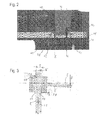
Figur 2 eine Draufsicht auf die erfindungsgemäße Befestigungsvorrichtung des Parallelanschlags ausFigur 1 , -
Figur 3 eine schematische Ansicht eines Federelements der Befestigungsvorrichtung ausFigur 1 . - In
Figur 1 ist ein Ausschnitt eines Handwerkzeugs, hier einer Handkreissäge 10, dargestellt. Die Handkreissäge 10 hat ein Sägeblatt, das unter einer Schutzabdeckung 12 angeordnet und entlang einer Schnittlinie A ausgerichtet ist, und eine Werkzeugauflageplatte 14, die eine Aussparung aufweist, durch die das Sägeblatt auf der Unterseite 16 der Werkzeugauflageplatte 14 austritt. Die Handkreissäge 10 wird mit der Unterseite der Werkzeugauflageplatte 14 auf das zu bearbeitende Werkstück aufgelegt und in Richtung der Linie A geführt. - Um die Handkreissäge 10 sicher in Richtung der Linie A führen zu können, ist ein Anschlagelement 20 vorgesehen, das mit einer Befestigungsvorrichtung 18 an der Werkzeugauflageplatte 14 der Handkreissäge stufenlos arretiert werden kann. Das Anschlagelement 20 hat eine längliche Anschlagschiene 22, die U-förmig um die Werkzeugauflageplatte 14 geführt ist und ein Anschlagblech 24 trägt, das senkrecht zur Anschlagschiene 22 an dieser befestigt ist und parallel oder in der Linie A verläuft.
- Das Anschlagelement 20 kann, wie im Folgenden dargestellt wird, mit der Anschlagschiene 22 in einer Verschieberichtung R, die senkrecht zur Achse A verläuft, in der Befestigungsvorrichtung 18 verschoben und in dieser arretiert werden. Dadurch wird das Anschlagblech 24 in einem geeigneten Abstand vom Sägeblatt parallel zur Linie A ausgerichtet. Das Anschlagblech 24 kann beispielsweise an eine Führungsschiene oder an eine Kante des zu bearbeitenden Werkstücks angelegt und an dieser entlang geführt werden, sodass eine exakte Schnittführung der Handkreissäge 10 möglich ist.
- Die Befestigungsvorrichtung 18 weist eine Führung 26 auf, in der das Anschlagelement 20 bzw. die Anschlagschiene 22 in Verschieberichtung R geführt ist sowie eine Arretiervorrichtung 28, um das Anschlagelement 20 in der Befestigungsvorrichtung 18 arretieren zu können.
- Die Führung 26 ist hier durch ein U-förmiges Blech gebildet, mit einer auf der Werkzeugauflageplatte 14 befestigten Basis 30 sowie zwei rechtwinklig von der Werkzeugauflageplatte 14 abstehenden Schenkeln 32. Die Schenkel 32 weisen jeweils eine schlitzförmige Öffnung 34 auf, durch die das Anschlagelement 20 mit der Anschlagschiene 22 in Verschieberichtung R eingeschoben werden kann. Die Abmessungen der Öffnungen 34 entsprechen im Wesentlichen dem Querschnitt der Anschlagschiene 22, sodass diese in Verschieberichtung R verschiebbar in der Führung 26 gelagert und quer hierzu nahezu spielfrei gehalten ist.
- Wie insbesondere in
Figur 2 zu sehen ist, ist die Arretiervorrichtung 28 durch ein U-förmiges Blech mit einer Basis 36 sowie zwei als Federelement 38 ausgebildeten Schenkeln gebildet. Die Basis 36 ist parallel zur Verschieberichtung R ausgerichtet, die Federelemente 38 sind jeweils zu einer senkrecht auf der Verschieberichtung R stehenden Ebene E in unterschiedliche Richtungen geneigt, wobei die Winkel, die die Federelemente 38 mit der Ebene E einschließen, entgegengesetzt und betragsmäßig gleich groß sind. - Die Federelemente 38 sind jeweils mit einem Lagerungsende 40 an der Basis 36 schwenkbar gehalten und weisen ein freies Ende 42 auf. Die Federelemente 38 können also um die Lagerungsenden 40 verschwenkt werden, wodurch der Winkel der Federelemente 38 zur Anschlagschiene 22 verändert wird.
- Die Federelemente 38 haben jeweils eine Aussparung 44 in Form eines Schlitzes, durch die die Anschlagschiene 22 geführt ist.
- Die Funktion der Federelemente 38 wird im Folgenden anhand eines schematisch dargestellten Federelements 38 in
Figur 3 erläutert. Die Höhe der Aussparung 44 entspricht im Wesentlichen der Höhe der Anschlagschiene 22, kann aber auch größer gewählt werden. Es muss lediglich die Möglichkeit einer reibungsarmen Verschiebung in Verschieberichtung R sichergestellt sein. Die Breite B der Aussparung 44 ist größer gewählt als die Breite b der Anschlagschiene 22. - Das Federelement ist in der Grundposition, die hier als Arretierposition bezeichnet wird, zu einer senkrecht auf der Verschieberichtung R stehenden Ebene E geneigt, wodurch sich die Projektion der Aussparung 44 auf die Ebene E soweit verkürzt, dass die tatsächliche Einschubbreite B' kleiner ist als die Breite B und im Wesentlichen der Breite b der Anschlagschiene 22 entspricht. Das Federelement 38 verkantet in dieser Position mit der Anschlagschiene 22. Das heißt, die die Aussparung 44 begrenzenden, gegenüberliegenden Kanten 46, 48 gelangen mit der Anschlagschiene 22 in Kontakt. Durch die Federkraft F des Federelement 38, die das Federelement 38 weiter zu verschwenken sucht, wird an den Kanten 46, 48 jeweils eine im Wesentlichen senkrecht zur Verschieberichtung R gerichtete Klemmkraft F1, F2 auf die Anschlagschiene 22 ausgeübt. Durch die entgegengesetzten Klemmkräfte F1, F2 wird die Anschlagschiene 22 am Federelement 38 geklemmt bzw. verkantet. Die an die Kanten 46, 48 angrenzenden Flächen sind hier senkrecht zueinander angeordnet, sodass diese jeweils eine möglichst scharfe Kante bilden, wodurch die Klemmkraft erhöht werden kann.
- Zum Lösen der Arretierung wird das Federelement 38 gegen die Federkraft F in die Freigabeposition verschwenkt, in der der Winkel, den das Federelement 38 mit der Ebene E einschließt, flacher ist. Dadurch wird die tatsächliche Einschubbreite B' vergrößert, bis diese größer ist als die Breite b der Anschlagschiene 22. Aufgrund der größeren tatsächlichen Einschubbreite B' werden die Kanten 46, 48 von der Anschlagschiene 22 gelöst, sodass diese freigegeben wird und in Verschieberichtung R bewegt und ausgerichtet werden kann.
- Nach dem Lösen der Federelemente 38 kehren diese aufgrund der Federspannung automatisch wieder in die Arretierposition zurück, sodass eine schnelle und werkzeuglose Arretierung der Anschlagschiene 22 bzw. des Anschlagelement 20 möglich ist.
- Wird die Anschlagschiene 22 allerdings gegen die Einschubrichtung R bewegt, kann diese das Federelement 38 von der Arretierposition in die Freigabeposition mitnehmen, sodass ein Lösen der Anschlagschiene 22 möglich ist. Aus diesem Grund sind, wie in
Figur 1 und2 zu sehen ist, zwei Federelemente 38 vorgesehen, die bezüglich der Ebene E spiegelbildlich angeordnet sind. Die Federelemente 38 laufen zu ihren freien Enden 42 voneinander weg. - An den freien Enden sind Verdickungen zum leichteren Greifen und Zusammendrücken des U-förmigen Blechs vorgesehen (siehe
Figur 1 ). - Das bezüglich
Figur 2 linke Federelement 38 arretiert die Anschlagschiene 22 in Verschieberichtung R, das bezüglichFigur 2 rechte Federelement 38 arretiert diese gegen die Verschieberichtung R. Dadurch ist eine Arretierung in beide Richtung geschaffen und ein versehentliches Lösen ausgeschlossen. - Wie insbesondere in den
Figuren 1 und2 zu sehen ist, ist eine einfache Bedienung der Arretiervorrichtung 28 möglich, indem die freien Enden 42 der Federelemente 38, beispielsweise mit der Hand, ergriffen werden und gegeneinander gegen die Schenkel 32 der Führung 26 gedrückt werden. Zum Arretieren der Anschlagschiene 22 werden die Federelemente 38 losgelassen, sodass diese nach außen in die Arretierposition zurückfedern können. Somit ist ein einfaches und schnelles Verstellen des Anschlagelements 20 möglich. - Statt der hier gezeigten Ausführungsform ist es auch denkbar, dass die Federelemente 38 nicht direkt bedient werden, sondern ein zusätzliches Betätigungselement vorgesehen ist, das die Federelemente 38 bewegt. Dies ermöglicht eine freiere Anordnung der Befestigungsvorrichtung 18 und somit des Anschlagelements 20 auf der Werkstückauflageplatte 14. Diese können beispielsweise auch geschützt innerhalb des Gehäuses der Handkreissäge 10 angeordnet sein. Zudem ist es denkbar, dass ein gemeinsames Betätigungselement für beide Federelemente 38 vorgesehen ist, sodass diese gleichmäßig bedient werden. Das Bedienelement kann beispielsweise ein Exzenter sein.
Claims (13)
- Befestigungsvorrichtung (18) für ein Anschlagelement (20) eines elektrischen Handwerkzeugs, insbesondere einer Handkreissäge (10), mit einer Führung (26), in die das Anschlagelement (20) eingeschoben und längs derselben verschoben werden kann, und einer Arretiervorrichtung (28), die das Anschlagelement (20) in Verschieberichtung (R) arretieren kann,
dadurch gekennzeichnet, dass die Arretiervorrichtung (28) ein Federelement (38) aufweist, welches in seiner Arretierposition das Anschlagelement (20) vorzugsweise mit einer gegen das Anschlagelement (20) gerichteten Klemmkraft klemmt und in einer Freigabeposition eine Verschiebung des Anschlagelements (20) erlaubt. - Befestigungsvorrichtung nach Anspruch 1, dadurch gekennzeichnet, dass das Federelement (38) eine Aussparung (44) aufweist, durch die sich das Anschlagelement (20) erstreckt.
- Befestigungsvorrichtung nach Anspruch 2, dadurch gekennzeichnet, dass sich das Federelement (38) in der Arretierposition gegenüber dem Anschlagelement (20) verkantet und dadurch das Anschlagelement (20) arretiert.
- Befestigungsvorrichtung nach Anspruch 2 oder 3, dadurch gekennzeichnet, dass die Aussparung (44) ein Schlitz ist, dessen Höhe vorzugsweise im Wesentlichen der des Anschlagelements (20) entspricht und dessen Länge vorzugsweise größer als die Breite des Anschlagelements (20) ist.
- Befestigungsvorrichtung nach einem der Ansprüche 2 bis 4, dadurch gekennzeichnet, dass die Aussparung (44) durch Kanten (46, 48) an dem Federelement (38) begrenzt ist, wobei die die Kanten begrenzenden Flächen vorzugsweise rechtwinkelig aufeinandertreffen, insbesondere zur Bildung einer scharfen Kante.
- Befestigungsvorrichtung nach einem der vorhergehenden Ansprüche, dadurch gekennzeichnet, dass das Federelement (38) ein Lagerungsende (40) sowie ein frei auskragendes Ende (42) hat und vorzugsweise langgestreckt ausgeführt ist.
- Befestigungsvorrichtung nach einem der vorhergehenden Ansprüche, dadurch gekennzeichnet, dass das Federelement (38) in Arretierposition schräg zur Einschubrichtung (R) verläuft und gegen das Anschlagelement (20) drückt.
- Befestigungsvorrichtung nach einem der vorhergehenden Ansprüche, dadurch gekennzeichnet, dass zwei Federelemente (38) vorgesehen sind, die bezüglich der Einschubrichtung (R) des Anschlagelements (20) schräg und nicht parallel zueinander verlaufen.
- Befestigungsvorrichtung nach Anspruch 8, dadurch gekennzeichnet, dass die Federelemente (38) einstückig miteinander verbunden sind, vorzugsweise unter Bildung eines U, mit einem in Richtung der Einschubrichtung (R) verlaufenden Basis (36) und zwei dazu geneigten Federelementen (38), wobei das U insbesondere spiegelbildlich zu einer Ebene senkrecht zur Einschubrichtung (R) ausgeführt ist.
- Befestigungsvorrichtung nach einem der Ansprüche 8 und 9, dadurch gekennzeichnet, dass die Federelemente (38) in Einschubrichtung (R) des Anschlagelements (20) vor und hinter der Führung (26) angeordnet sind.
- Befestigungsvorrichtung nach einem der vorhergehenden Ansprüche, dadurch gekennzeichnet, dass ein zusätzliches Betätigungselement zur Bedienung des Federelements (38) vorgesehen ist, insbesondere ein Exzenter.
- Parallelführung an einer elektrischen Handsäge, mit einer Befestigungsvorrichtung (18) nach einem der vorhergehenden Ansprüche und mit einem Anschlagelement (20), welches in die Führung (26) eingeschoben und durch die Arretiervorrichtung (28) lösbar arretiert ist.
- Parallelführung nach Anspruch 12, dadurch gekennzeichnet, dass das Anschlagelement (20) eine geringere Härte als das Federelement (38) hat.
Applications Claiming Priority (1)
| Application Number | Priority Date | Filing Date | Title |
|---|---|---|---|
| DE102010038675A DE102010038675A1 (de) | 2010-07-30 | 2010-07-30 | Befestigungsvorrichtung |
Publications (2)
| Publication Number | Publication Date |
|---|---|
| EP2412490A1 true EP2412490A1 (de) | 2012-02-01 |
| EP2412490B1 EP2412490B1 (de) | 2017-08-23 |
Family
ID=44533486
Family Applications (1)
| Application Number | Title | Priority Date | Filing Date |
|---|---|---|---|
| EP11173179.0A Active EP2412490B1 (de) | 2010-07-30 | 2011-07-08 | Befestigungsvorrichtung |
Country Status (5)
| Country | Link |
|---|---|
| US (1) | US8650761B2 (de) |
| EP (1) | EP2412490B1 (de) |
| JP (1) | JP5852351B2 (de) |
| CN (1) | CN102343524B (de) |
| DE (1) | DE102010038675A1 (de) |
Families Citing this family (7)
| Publication number | Priority date | Publication date | Assignee | Title |
|---|---|---|---|---|
| US10486251B2 (en) * | 2016-05-16 | 2019-11-26 | Makita Corporation | Machining devices |
| CN106313188A (zh) * | 2016-10-17 | 2017-01-11 | 四川唯诺家私有限公司 | 便于手提式电圆锯切割木板的装置 |
| CN108457070A (zh) * | 2018-04-25 | 2018-08-28 | 李松 | 一种便携式窗帘裁高机 |
| JP7103002B2 (ja) * | 2018-07-13 | 2022-07-20 | 工機ホールディングス株式会社 | 切断機 |
| WO2021010136A1 (ja) * | 2019-07-12 | 2021-01-21 | 工機ホールディングス株式会社 | 動力工具 |
| USD1119500S1 (en) | 2021-03-09 | 2026-03-24 | Bam Ip Holding Llc | Track saw guide |
| US11883891B2 (en) * | 2021-03-09 | 2024-01-30 | Nomis Llc | Track saw |
Citations (3)
| Publication number | Priority date | Publication date | Assignee | Title |
|---|---|---|---|---|
| US4628608A (en) * | 1984-04-06 | 1986-12-16 | Robert Bosch Gmbh | Guide device for hand-held machine tools |
| GB2319987A (en) * | 1996-12-07 | 1998-06-10 | Bosch Gmbh Robert | Hand tool machine with a parallel guide |
| US20060005404A1 (en) * | 2004-04-15 | 2006-01-12 | Nomis, Llc | Adjustable guide rail for hand tools |
Family Cites Families (20)
| Publication number | Priority date | Publication date | Assignee | Title |
|---|---|---|---|---|
| US1355724A (en) * | 1918-10-14 | 1920-10-12 | Dmitry V Zhukoff | Calipers |
| US2002676A (en) * | 1933-08-21 | 1935-05-28 | John C Steele | Stone cutter gauge |
| US2800933A (en) * | 1956-06-08 | 1957-07-30 | Don L Michael | Rip guide for portable electric saws |
| US3043351A (en) * | 1960-09-12 | 1962-07-10 | Portable Electric Tools Inc | Edge guide for use with powered hand saws |
| US3087519A (en) * | 1960-11-25 | 1963-04-30 | Black & Decker Mfg Co | Pivoting shoe for portable electric jig saw |
| US4128940A (en) * | 1977-10-20 | 1978-12-12 | Ong Jose K | Guide and adaptor for hand saws |
| DE8024714U1 (de) * | 1980-09-16 | 1982-02-04 | Robert Bosch Gmbh, 7000 Stuttgart | Führungsvorrichtung für eine Handwerkzeugmaschine |
| US4356748A (en) * | 1980-10-02 | 1982-11-02 | Tilton Charles W | Saw guide |
| US5035061A (en) * | 1990-01-02 | 1991-07-30 | Timothy Bradbury | Guide for hand-held power tools |
| US5427006A (en) * | 1994-07-26 | 1995-06-27 | Finley; Joe | Circular saw guide |
| US5964041A (en) * | 1997-08-04 | 1999-10-12 | Daniel; Jerry R. | Guide tool |
| US5901450A (en) * | 1997-11-21 | 1999-05-11 | Milwaukee Electric Tool Corporation | Rip guide for a circular saw |
| US6757981B2 (en) * | 2002-07-19 | 2004-07-06 | Philip W. Hampton | Universal rip guide for circular saw |
| US20040011179A1 (en) * | 2002-07-22 | 2004-01-22 | Rabell Roberto Jaime | Drywall t-square circular saw holder attachment |
| US7043845B2 (en) * | 2004-08-27 | 2006-05-16 | Lukens Charles R | Trim attachment for portable circular saw |
| JP4600184B2 (ja) * | 2005-06-30 | 2010-12-15 | 日立工機株式会社 | ガイド及びこれを備えた携帯用切断工具 |
| US7661194B1 (en) * | 2006-04-28 | 2010-02-16 | K & E Enterprises, Inc. | Rolling plate assembly attachment for portable power cutting tools |
| DE602007011426D1 (de) * | 2007-07-26 | 2011-02-03 | Black & Decker Inc | Anti-Rückstoß-Vorrichtung |
| US7950156B2 (en) * | 2008-02-19 | 2011-05-31 | Black & Decker Inc. | Power tools |
| WO2009130938A1 (ja) * | 2008-04-21 | 2009-10-29 | 株式会社 マキタ | 卓上丸鋸盤用治具及び卓上丸鋸盤 |
-
2010
- 2010-07-30 DE DE102010038675A patent/DE102010038675A1/de not_active Ceased
-
2011
- 2011-07-08 EP EP11173179.0A patent/EP2412490B1/de active Active
- 2011-07-27 CN CN201110211024.8A patent/CN102343524B/zh active Active
- 2011-07-28 US US13/193,305 patent/US8650761B2/en active Active
- 2011-08-01 JP JP2011168759A patent/JP5852351B2/ja active Active
Patent Citations (3)
| Publication number | Priority date | Publication date | Assignee | Title |
|---|---|---|---|---|
| US4628608A (en) * | 1984-04-06 | 1986-12-16 | Robert Bosch Gmbh | Guide device for hand-held machine tools |
| GB2319987A (en) * | 1996-12-07 | 1998-06-10 | Bosch Gmbh Robert | Hand tool machine with a parallel guide |
| US20060005404A1 (en) * | 2004-04-15 | 2006-01-12 | Nomis, Llc | Adjustable guide rail for hand tools |
Also Published As
| Publication number | Publication date |
|---|---|
| JP2012030357A (ja) | 2012-02-16 |
| EP2412490B1 (de) | 2017-08-23 |
| US8650761B2 (en) | 2014-02-18 |
| DE102010038675A1 (de) | 2012-02-02 |
| US20120192437A1 (en) | 2012-08-02 |
| CN102343524B (zh) | 2016-06-22 |
| JP5852351B2 (ja) | 2016-02-03 |
| CN102343524A (zh) | 2012-02-08 |
Similar Documents
| Publication | Publication Date | Title |
|---|---|---|
| EP2412490B1 (de) | Befestigungsvorrichtung | |
| EP1377403B1 (de) | Lösbarer werkzeugbefestigungsmechanismus und werkzeug zur verwendung damit | |
| DE102015220810B3 (de) | Spannstock | |
| EP2412466B1 (de) | Stichsäge mit einer Sägeblattaufnahme | |
| EP2183072A1 (de) | Handwerkzeugmaschine | |
| DE202018103332U1 (de) | Linealadapter | |
| EP1995024A1 (de) | Handgeführtes Arbeitsgerät | |
| EP2018922A2 (de) | Kreissägenständer | |
| EP1809441A1 (de) | Spann- oder greifvorrichtung insbesondere linear- oder zentrischgreifer | |
| EP2849907B1 (de) | Vorrichtung zum fixieren eines mittels einer bearbeitungsmaschine zu bearbeitenden werkstücks | |
| DE69524046T2 (de) | Sägeblattaufspannvorrichtung | |
| EP1944135B1 (de) | Spannwerkzeug mit einem Standfuß | |
| DE19926387A1 (de) | Werkzeugabstützvorrichtung für ein handgeführtes Arbeitsgerät | |
| EP0274746B1 (de) | Spannzwinge mit verstellbaren Spanngliedern | |
| DE202010011826U1 (de) | Holzbearbeitungsmaschine und dafür geeignetes Gehrungsanschlagsmodul | |
| EP4286084A1 (de) | Spannvorrichtung für eine kreissäge | |
| EP3702100B1 (de) | Anschlagvorrichtung | |
| DE102009036308B4 (de) | Sägeblattklemme | |
| DE202022100251U1 (de) | Winkelanschlag | |
| DE202021104502U1 (de) | Fixierwerkzeug, Fixierwerkzeugsatz sowie Zubehörsatz zur Benutzung zusammen mit einem tragbaren Bearbeitungsgerät | |
| DE8516029U1 (de) | Längsführung, insbesondere für eine Kreissäge | |
| DE202020107144U1 (de) | Tragbare Bearbeitungsmaschine | |
| DE102019204732A1 (de) | Sperrmechanismus für eine tischkreissäge und anwendungsverfahren dafür | |
| DE102019110984A1 (de) | Klemmhalter | |
| DE10334336A1 (de) | Schraubzwinge |
Legal Events
| Date | Code | Title | Description |
|---|---|---|---|
| AK | Designated contracting states |
Kind code of ref document: A1 Designated state(s): AL AT BE BG CH CY CZ DE DK EE ES FI FR GB GR HR HU IE IS IT LI LT LU LV MC MK MT NL NO PL PT RO RS SE SI SK SM TR |
|
| AX | Request for extension of the european patent |
Extension state: BA ME |
|
| PUAI | Public reference made under article 153(3) epc to a published international application that has entered the european phase |
Free format text: ORIGINAL CODE: 0009012 |
|
| 17P | Request for examination filed |
Effective date: 20120801 |
|
| GRAP | Despatch of communication of intention to grant a patent |
Free format text: ORIGINAL CODE: EPIDOSNIGR1 |
|
| RIC1 | Information provided on ipc code assigned before grant |
Ipc: B25H 1/00 20060101AFI20170316BHEP |
|
| INTG | Intention to grant announced |
Effective date: 20170405 |
|
| GRAS | Grant fee paid |
Free format text: ORIGINAL CODE: EPIDOSNIGR3 |
|
| GRAA | (expected) grant |
Free format text: ORIGINAL CODE: 0009210 |
|
| AK | Designated contracting states |
Kind code of ref document: B1 Designated state(s): AL AT BE BG CH CY CZ DE DK EE ES FI FR GB GR HR HU IE IS IT LI LT LU LV MC MK MT NL NO PL PT RO RS SE SI SK SM TR |
|
| REG | Reference to a national code |
Ref country code: GB Ref legal event code: FG4D Free format text: NOT ENGLISH |
|
| REG | Reference to a national code |
Ref country code: CH Ref legal event code: EP |
|
| REG | Reference to a national code |
Ref country code: AT Ref legal event code: REF Ref document number: 920832 Country of ref document: AT Kind code of ref document: T Effective date: 20170915 |
|
| REG | Reference to a national code |
Ref country code: IE Ref legal event code: FG4D Free format text: LANGUAGE OF EP DOCUMENT: GERMAN |
|
| REG | Reference to a national code |
Ref country code: DE Ref legal event code: R096 Ref document number: 502011012837 Country of ref document: DE |
|
| REG | Reference to a national code |
Ref country code: NL Ref legal event code: MP Effective date: 20170823 |
|
| REG | Reference to a national code |
Ref country code: LT Ref legal event code: MG4D |
|
| PG25 | Lapsed in a contracting state [announced via postgrant information from national office to epo] |
Ref country code: NL Free format text: LAPSE BECAUSE OF FAILURE TO SUBMIT A TRANSLATION OF THE DESCRIPTION OR TO PAY THE FEE WITHIN THE PRESCRIBED TIME-LIMIT Effective date: 20170823 Ref country code: LT Free format text: LAPSE BECAUSE OF FAILURE TO SUBMIT A TRANSLATION OF THE DESCRIPTION OR TO PAY THE FEE WITHIN THE PRESCRIBED TIME-LIMIT Effective date: 20170823 Ref country code: FI Free format text: LAPSE BECAUSE OF FAILURE TO SUBMIT A TRANSLATION OF THE DESCRIPTION OR TO PAY THE FEE WITHIN THE PRESCRIBED TIME-LIMIT Effective date: 20170823 Ref country code: HR Free format text: LAPSE BECAUSE OF FAILURE TO SUBMIT A TRANSLATION OF THE DESCRIPTION OR TO PAY THE FEE WITHIN THE PRESCRIBED TIME-LIMIT Effective date: 20170823 Ref country code: SE Free format text: LAPSE BECAUSE OF FAILURE TO SUBMIT A TRANSLATION OF THE DESCRIPTION OR TO PAY THE FEE WITHIN THE PRESCRIBED TIME-LIMIT Effective date: 20170823 Ref country code: NO Free format text: LAPSE BECAUSE OF FAILURE TO SUBMIT A TRANSLATION OF THE DESCRIPTION OR TO PAY THE FEE WITHIN THE PRESCRIBED TIME-LIMIT Effective date: 20171123 |
|
| PG25 | Lapsed in a contracting state [announced via postgrant information from national office to epo] |
Ref country code: PL Free format text: LAPSE BECAUSE OF FAILURE TO SUBMIT A TRANSLATION OF THE DESCRIPTION OR TO PAY THE FEE WITHIN THE PRESCRIBED TIME-LIMIT Effective date: 20170823 Ref country code: IS Free format text: LAPSE BECAUSE OF FAILURE TO SUBMIT A TRANSLATION OF THE DESCRIPTION OR TO PAY THE FEE WITHIN THE PRESCRIBED TIME-LIMIT Effective date: 20171223 Ref country code: GR Free format text: LAPSE BECAUSE OF FAILURE TO SUBMIT A TRANSLATION OF THE DESCRIPTION OR TO PAY THE FEE WITHIN THE PRESCRIBED TIME-LIMIT Effective date: 20171124 Ref country code: LV Free format text: LAPSE BECAUSE OF FAILURE TO SUBMIT A TRANSLATION OF THE DESCRIPTION OR TO PAY THE FEE WITHIN THE PRESCRIBED TIME-LIMIT Effective date: 20170823 Ref country code: ES Free format text: LAPSE BECAUSE OF FAILURE TO SUBMIT A TRANSLATION OF THE DESCRIPTION OR TO PAY THE FEE WITHIN THE PRESCRIBED TIME-LIMIT Effective date: 20170823 Ref country code: RS Free format text: LAPSE BECAUSE OF FAILURE TO SUBMIT A TRANSLATION OF THE DESCRIPTION OR TO PAY THE FEE WITHIN THE PRESCRIBED TIME-LIMIT Effective date: 20170823 Ref country code: BG Free format text: LAPSE BECAUSE OF FAILURE TO SUBMIT A TRANSLATION OF THE DESCRIPTION OR TO PAY THE FEE WITHIN THE PRESCRIBED TIME-LIMIT Effective date: 20171123 |
|
| PG25 | Lapsed in a contracting state [announced via postgrant information from national office to epo] |
Ref country code: RO Free format text: LAPSE BECAUSE OF FAILURE TO SUBMIT A TRANSLATION OF THE DESCRIPTION OR TO PAY THE FEE WITHIN THE PRESCRIBED TIME-LIMIT Effective date: 20170823 Ref country code: DK Free format text: LAPSE BECAUSE OF FAILURE TO SUBMIT A TRANSLATION OF THE DESCRIPTION OR TO PAY THE FEE WITHIN THE PRESCRIBED TIME-LIMIT Effective date: 20170823 Ref country code: CZ Free format text: LAPSE BECAUSE OF FAILURE TO SUBMIT A TRANSLATION OF THE DESCRIPTION OR TO PAY THE FEE WITHIN THE PRESCRIBED TIME-LIMIT Effective date: 20170823 |
|
| REG | Reference to a national code |
Ref country code: DE Ref legal event code: R097 Ref document number: 502011012837 Country of ref document: DE |
|
| PG25 | Lapsed in a contracting state [announced via postgrant information from national office to epo] |
Ref country code: SK Free format text: LAPSE BECAUSE OF FAILURE TO SUBMIT A TRANSLATION OF THE DESCRIPTION OR TO PAY THE FEE WITHIN THE PRESCRIBED TIME-LIMIT Effective date: 20170823 Ref country code: SM Free format text: LAPSE BECAUSE OF FAILURE TO SUBMIT A TRANSLATION OF THE DESCRIPTION OR TO PAY THE FEE WITHIN THE PRESCRIBED TIME-LIMIT Effective date: 20170823 Ref country code: IT Free format text: LAPSE BECAUSE OF FAILURE TO SUBMIT A TRANSLATION OF THE DESCRIPTION OR TO PAY THE FEE WITHIN THE PRESCRIBED TIME-LIMIT Effective date: 20170823 Ref country code: EE Free format text: LAPSE BECAUSE OF FAILURE TO SUBMIT A TRANSLATION OF THE DESCRIPTION OR TO PAY THE FEE WITHIN THE PRESCRIBED TIME-LIMIT Effective date: 20170823 |
|
| PLBE | No opposition filed within time limit |
Free format text: ORIGINAL CODE: 0009261 |
|
| STAA | Information on the status of an ep patent application or granted ep patent |
Free format text: STATUS: NO OPPOSITION FILED WITHIN TIME LIMIT |
|
| REG | Reference to a national code |
Ref country code: FR Ref legal event code: PLFP Year of fee payment: 8 |
|
| 26N | No opposition filed |
Effective date: 20180524 |
|
| PG25 | Lapsed in a contracting state [announced via postgrant information from national office to epo] |
Ref country code: SI Free format text: LAPSE BECAUSE OF FAILURE TO SUBMIT A TRANSLATION OF THE DESCRIPTION OR TO PAY THE FEE WITHIN THE PRESCRIBED TIME-LIMIT Effective date: 20170823 |
|
| PG25 | Lapsed in a contracting state [announced via postgrant information from national office to epo] |
Ref country code: MT Free format text: LAPSE BECAUSE OF FAILURE TO SUBMIT A TRANSLATION OF THE DESCRIPTION OR TO PAY THE FEE WITHIN THE PRESCRIBED TIME-LIMIT Effective date: 20170823 |
|
| REG | Reference to a national code |
Ref country code: CH Ref legal event code: PL |
|
| PG25 | Lapsed in a contracting state [announced via postgrant information from national office to epo] |
Ref country code: LU Free format text: LAPSE BECAUSE OF NON-PAYMENT OF DUE FEES Effective date: 20180708 Ref country code: MC Free format text: LAPSE BECAUSE OF FAILURE TO SUBMIT A TRANSLATION OF THE DESCRIPTION OR TO PAY THE FEE WITHIN THE PRESCRIBED TIME-LIMIT Effective date: 20170823 |
|
| REG | Reference to a national code |
Ref country code: BE Ref legal event code: MM Effective date: 20180731 |
|
| REG | Reference to a national code |
Ref country code: IE Ref legal event code: MM4A |
|
| PG25 | Lapsed in a contracting state [announced via postgrant information from national office to epo] |
Ref country code: CH Free format text: LAPSE BECAUSE OF NON-PAYMENT OF DUE FEES Effective date: 20180731 Ref country code: LI Free format text: LAPSE BECAUSE OF NON-PAYMENT OF DUE FEES Effective date: 20180731 Ref country code: IE Free format text: LAPSE BECAUSE OF NON-PAYMENT OF DUE FEES Effective date: 20180708 |
|
| PG25 | Lapsed in a contracting state [announced via postgrant information from national office to epo] |
Ref country code: BE Free format text: LAPSE BECAUSE OF NON-PAYMENT OF DUE FEES Effective date: 20180731 |
|
| REG | Reference to a national code |
Ref country code: AT Ref legal event code: MM01 Ref document number: 920832 Country of ref document: AT Kind code of ref document: T Effective date: 20180708 |
|
| PGFP | Annual fee paid to national office [announced via postgrant information from national office to epo] |
Ref country code: FR Payment date: 20190719 Year of fee payment: 9 |
|
| PG25 | Lapsed in a contracting state [announced via postgrant information from national office to epo] |
Ref country code: AT Free format text: LAPSE BECAUSE OF NON-PAYMENT OF DUE FEES Effective date: 20180708 |
|
| PGFP | Annual fee paid to national office [announced via postgrant information from national office to epo] |
Ref country code: GB Payment date: 20190719 Year of fee payment: 9 |
|
| PG25 | Lapsed in a contracting state [announced via postgrant information from national office to epo] |
Ref country code: TR Free format text: LAPSE BECAUSE OF FAILURE TO SUBMIT A TRANSLATION OF THE DESCRIPTION OR TO PAY THE FEE WITHIN THE PRESCRIBED TIME-LIMIT Effective date: 20170823 |
|
| PG25 | Lapsed in a contracting state [announced via postgrant information from national office to epo] |
Ref country code: HU Free format text: LAPSE BECAUSE OF FAILURE TO SUBMIT A TRANSLATION OF THE DESCRIPTION OR TO PAY THE FEE WITHIN THE PRESCRIBED TIME-LIMIT; INVALID AB INITIO Effective date: 20110708 Ref country code: PT Free format text: LAPSE BECAUSE OF FAILURE TO SUBMIT A TRANSLATION OF THE DESCRIPTION OR TO PAY THE FEE WITHIN THE PRESCRIBED TIME-LIMIT Effective date: 20170823 |
|
| PG25 | Lapsed in a contracting state [announced via postgrant information from national office to epo] |
Ref country code: CY Free format text: LAPSE BECAUSE OF FAILURE TO SUBMIT A TRANSLATION OF THE DESCRIPTION OR TO PAY THE FEE WITHIN THE PRESCRIBED TIME-LIMIT Effective date: 20170823 Ref country code: MK Free format text: LAPSE BECAUSE OF NON-PAYMENT OF DUE FEES Effective date: 20170823 |
|
| PG25 | Lapsed in a contracting state [announced via postgrant information from national office to epo] |
Ref country code: AL Free format text: LAPSE BECAUSE OF FAILURE TO SUBMIT A TRANSLATION OF THE DESCRIPTION OR TO PAY THE FEE WITHIN THE PRESCRIBED TIME-LIMIT Effective date: 20170823 |
|
| GBPC | Gb: european patent ceased through non-payment of renewal fee |
Effective date: 20200708 |
|
| PG25 | Lapsed in a contracting state [announced via postgrant information from national office to epo] |
Ref country code: FR Free format text: LAPSE BECAUSE OF NON-PAYMENT OF DUE FEES Effective date: 20200731 Ref country code: GB Free format text: LAPSE BECAUSE OF NON-PAYMENT OF DUE FEES Effective date: 20200708 |
|
| PGFP | Annual fee paid to national office [announced via postgrant information from national office to epo] |
Ref country code: DE Payment date: 20250722 Year of fee payment: 15 |