EP2409591A2 - Elektrischer Schalter - Google Patents
Elektrischer Schalter Download PDFInfo
- Publication number
- EP2409591A2 EP2409591A2 EP11167884A EP11167884A EP2409591A2 EP 2409591 A2 EP2409591 A2 EP 2409591A2 EP 11167884 A EP11167884 A EP 11167884A EP 11167884 A EP11167884 A EP 11167884A EP 2409591 A2 EP2409591 A2 EP 2409591A2
- Authority
- EP
- European Patent Office
- Prior art keywords
- substrate
- electrical pin
- electric
- button
- electric component
- Prior art date
- Legal status (The legal status is an assumption and is not a legal conclusion. Google has not performed a legal analysis and makes no representation as to the accuracy of the status listed.)
- Withdrawn
Links
- 239000000758 substrate Substances 0.000 claims abstract description 69
- 239000004744 fabric Substances 0.000 claims abstract description 25
- 238000007789 sealing Methods 0.000 claims abstract description 5
- 239000003990 capacitor Substances 0.000 claims description 4
- 238000005516 engineering process Methods 0.000 description 5
- 238000004519 manufacturing process Methods 0.000 description 4
- 230000003287 optical effect Effects 0.000 description 4
- 239000000463 material Substances 0.000 description 3
- 238000010292 electrical insulation Methods 0.000 description 2
- 238000001746 injection moulding Methods 0.000 description 2
- 238000012986 modification Methods 0.000 description 2
- 230000004048 modification Effects 0.000 description 2
- 238000009958 sewing Methods 0.000 description 2
- 230000002411 adverse Effects 0.000 description 1
- 239000003086 colorant Substances 0.000 description 1
- 230000009977 dual effect Effects 0.000 description 1
- 238000002955 isolation Methods 0.000 description 1
- 238000000034 method Methods 0.000 description 1
- 239000000243 solution Substances 0.000 description 1
- 238000003466 welding Methods 0.000 description 1
Images
Classifications
-
- A—HUMAN NECESSITIES
- A44—HABERDASHERY; JEWELLERY
- A44B—BUTTONS, PINS, BUCKLES, SLIDE FASTENERS, OR THE LIKE
- A44B1/00—Buttons
- A44B1/04—Ornamental buttons
-
- A—HUMAN NECESSITIES
- A44—HABERDASHERY; JEWELLERY
- A44B—BUTTONS, PINS, BUCKLES, SLIDE FASTENERS, OR THE LIKE
- A44B1/00—Buttons
- A44B1/18—Buttons adapted for special ways of fastening
-
- A—HUMAN NECESSITIES
- A44—HABERDASHERY; JEWELLERY
- A44C—PERSONAL ADORNMENTS, e.g. JEWELLERY; COINS
- A44C15/00—Other forms of jewellery
- A44C15/0015—Illuminated or sound-producing jewellery
Definitions
- the present invention provides an electric button and a light emitting diode (LED) module.
- the present invention provides an electric button that can be loaded with an electric component and an LED button module in a button form.
- buttons have been used for many years for buttoning and ornamental purposes on clothing and fabrics in human society. Although their functions are only limited thereto, buttons are one of the most essential and indispensable clothing accessories in clothing.
- An objective of the present invention is to integrate an electric component into a clothing accessory (e.g., a button) so that a conventional button can not only perform the traditional buttoning and ornament functions but also have an electric component, thereby adding new functions to clothing and fabrics for the users' convenience.
- a clothing accessory e.g., a button
- an embodiment of the present invention provides an electric button, which comprises a substrate, at least one electric component and a mask.
- the electric component is electrically connected to and fixedly disposed on a surface of the substrate.
- the mask seals the electric component on the surface of the substrate.
- the substrate is sewed onto the fabric by at least one conductive thread, and is electrically connected to the conductive thread.
- the electric component comprises a light emitting diode (LED), a resistor, a capacitor, a switch, an inductor, a speaker, an integrated circuit (IC) chip, the like, or a combination thereof.
- Another embodiment of the present invention further provides an electric button, which comprises a substrate, at least one electric component, at least one conductive thread and a mask.
- the conductive thread fixedly disposes the electric component on the surface of the substrate, and is electrically connected to the electric component.
- the mask seals the electric component on the surface of the substrate.
- the substrate is sewed on the fabric by the conductive thread.
- the electric component comprises an LED, a resistor, a capacitor, a switch, an inductor, a speaker, an IC chip, the like, or a combination thereof.
- the aforesaid two kinds of electric buttons in different ways, can have the electric component integrated into a conventional button or can directly replace the functions of the conventional button so that the functions of the electric component can be additionally provided in the conventional common button to create new application fields and functions.
- an LED button module which comprises a substrate, a first electrical pin, a second electrical pin, an LED die and a mask.
- the substrate has a plurality of through holes formed therein.
- the first electrical pin, the second electrical pin and the LED die are all fixedly disposed on a surface of the substrate.
- the LED die is electrically connected to the first electrical pin and the second electrical pin respectively.
- the mask seals the LED die on the surface of the substrate.
- the substrate is sewed onto the fabric by a conductive thread through the through holes, and the conductive thread is electrically connected to the first electrical pin and the second electrical pin.
- an LED button module which comprises a first electrical pin, a second electrical pin, an LED die and an enclosure.
- the first electrical pin and the second electrical pin are electrically connected to the LED die
- the enclosure of the LED button module comprises at least one through hole formed therein so that the enclosure is sewed onto the fabric by at least one conductive thread through the through hole.
- the enclosure can be formed with a base and a housing portion, which are integrally formed, simultaneously through injection molding from a plastic.
- the base supports the LED die, the first electrical pin and the second electrical pin, while the housing portion seals the first electrical pin, the second electrical pin and the LED die.
- the LED button module of the present invention can be sewed onto the fabric just like a conventional button.
- the LED button module can also serve various LED to create new applications of the fabric.
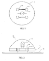
- the electric button 10 of the present invention comprises a substrate 11, at least one electric component 13 and a mask 15.
- the substrate 11 has a plurality of through holes 111 formed therein; for example, the substrate 11 has four through holes 111 distributed therein.
- the through holes 111 function like the through holes of a conventional button, through which the button is fastened onto the fabric by a thread.
- the number and the form of the aforesaid through holes 111 are only intended to illustrate the present invention but not to limit the present invention.
- buttons may also be applied to the present invention.
- at least one lateral opening may be disposed in the lower part of the substrate to sew the substrate onto the fabric; a set of male and female buttons may also be disposed on the lower part of the substrate to fasten the substrate on the fabric.
- the substrate 11 of this embodiment can be sewed onto the fabric 93 by a conductive thread 91 through the through holes 111, and the substrate 11 and the conductive thread 91 are electrically connected to each other.
- the substrate 11 should be a printed circuit board (PCB) to support and electrically connect to the electric component 13.
- PCB printed circuit board
- the conductive thread 91 of this embodiment adopts a technology described by the present applicant in U.S. Patent Application No. 12/569,882 (corresponding to Taiwan Patent Application No. 099102066 ) filed on September 29, 2009. This U.S. Patent Application is incorporated herein by reference, so this technology will not be further described herein.
- the electric component 13 of this embodiment is electrically connected to a printed circuit and fixedly disposed onto the surface of the substrate 11 preferably by a surface mount technology (SMT) and a welding process.
- the electric component 13 may comprise at least a light emitting diode (LED), a resistor, a capacitor, a switch, an inductor, a speaker and an integrated circuit (IC) chip or a combination thereof;
- LED light emitting diode
- IC integrated circuit
- the electric button 10 of the present invention has a mask 15 adapted to seal the electric component 13 on the surface of the substrate 11. Furthermore, the mask 15 is adapted to seal most of the area of the electric component 13 and the substrate 11 except the through holes so that the electric component 13 and/or the substrate 11 are not influenced by adverse factors of the ambient environment; as a result, both a satisfactory electrical insulation from the ambient environment and an aesthetic appearance can be achieved.
- the mask 15 may have a planar shape, a spherical shape or a parabolic shape; and depending on the actual requirements, the mask 15 can be a sealing mask and can have at least one transparent or translucent area.
- the at least one transparent or translucent area may be disposed on the mask to facilitate full functioning of the electric component.
- an external power supply (not shown) is applied to the substrate 11 through the conductive thread 91, and is then electrically connected to the electric component 13 through a printed circuit of the substrate 11 to operate the electric component 13.
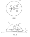
- FIGs. 3 and 4 illustrate a top view and a side view illustrating the second embodiment of an electric button 30 of the present invention.
- the electric button 30 of the present invention comprises a substrate 31, at least one electric component 33, at least one conductive thread 91 and a mask 35.
- the second embodiment of the electric button of the present invention is similar to the first embodiment of the electric button 10 except that the electrical connection relationship between the individual components is different.
- the substrate 31 is a carrier like a conventional button, and is merely used to support the electric component 33 thereon but is not electrically connected to the electric component 33.
- the electric component 33 is electrically connected to the conductive thread 91 directly, and is fixedly disposed on the substrate 31 by the conductive thread 91.
- the conductive thread 91 further extends through the through holes 311 to sew the substrate 31 onto the fabric 93.
- an external power supply (not shown) is applied to the electric component 33 through the conductive thread 91 directly to operate the electric component 33.
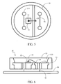
- FIGs. 5 and 6 illustrate the top view and side view, respectively, of an LED button module 50 of the present invention, wherein the LED button module 50 can be regarded as a third embodiment of the electric button of the invention.
- the LED button module 50 of the present invention is actually an LED module shaped as a button, and comprises a substrate 51, a first electrical pin 57, a second electrical pin 59, an LED die 53 and a mask 55.
- the substrate 51 has a plurality of through holes 511 formed therein so that the LED button module 50 can be fastened onto the fabric 93 by the conductive thread 91 extending through the through holes 511.
- the substrate 51 may be a printed circuit board (PCB), which is electrically connected to the conductive thread 91 to provide the power supply needed by the two electrical pins 57, 59 and the LED die 53.
- PCB printed circuit board
- the LED die 53 is fixedly disposed onto the substrate 51 directly, and is electrically connected to the first electrical pin 57 and the second electrical pin 59 of the substrate 51.
- the through holes 511 are disposed adjacent to the center position of the substrate 51, which is suitable for use in an automatic sewing machine (not shown) so that the substrate 51 can be quickly sewed onto the fabric 93 by the automatic sewing machine using the conductive thread 91 through the through holes 511. This facilitates an automatic mass production process.
- the conductive thread 91 is electrically connected to the first electrical pin 57 and the second electrical pin 59 through a printed circuit of the substrate 51.
- the LED button module 50 may be applied to a conductive fabric developed by the present applicant; for example, an LED module array may be formed to display an LED array signal (e.g., a marquee signal or an indicating signal) on the fabric.
- the LED button module 50 of the present invention has a mask 55.
- the mask 55 seals the LED die 53 on the surface of the substrate 51.
- the mask 55 seals most of the areas of the LED die 53 and the substrate 51 except the through holes for both electrical insulation and moisture isolation purposes to prolong the service life of the LED.
- an external power supply (not shown) is connected to the first electrical pin 57 and the second electrical pin 59 of the substrate 51 by the conductive thread 91 through the printed circuit of the substrate 51, and is then electrically connected to the LED die 53 through the first electrical pin 57 and the second electrical pin 59 so that the LED die 53 emits light.
- a cavity 553 may be formed between the mask 55 and the substrate 51 and be filled and coated with an appropriate optical material.
- different shapes, colors and transparency levels of the mask 55 may be developed to enlarge its application scope.
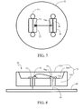
- FIGs. 7 and 8 illustrate the top view and side view of an LED button module 70 according to another embodiment of the present invention, wherein the LED button module 70 can be regarded as a fourth embodiment of the electric button of the invention.
- the LED button module 70 of this embodiment comprises a first electrical pin 77, a second electrical pin 79, an LED die 73 and an enclosure 75. Similar to the aforesaid embodiment, the LED die 73 of this embodiment is electrically connected to the first electrical pin 77 via a second electrical pin 79a to the second electrical pin 79.
- the enclosure 75 of the LED button module 70 comprises at least one through hole 711 formed therein so that the enclosure 75 is sewed onto the fabric 93 by at least one conductive thread 91 through the through hole 711.
- the LED button module 70 of this embodiment has the components of the aforesaid LED button module 50 further integrated to make the structure thereof more compact. This can simplify the production process, reduce the number of parts to be produced, reduce the manufacturing cost and facilitate commercialization of products.
- the enclosure 75 of this embodiment is a component that has the substrate 51 and the mask 55 integrally formed; in other words, the substrate 51 and the mask 55 are integrally formed to become the enclosure 75.
- the enclosure 75 of this embodiment may have a base 751 and a housing portion 755 integrally formed through injection molding from a plastic.
- the base 751 supports the LED die 73, the first electrical pin 77 and the second electrical pin 79, while the housing portion 755 seals the first electrical pin 77, the second electrical pin 79 and the LED die 73 to isolate moisture. It shall be appreciated that depending on the optical design requirements of the conventional LED module, a cavity 753 may be formed between the base 751 and the housing portion 755 and be filled and coated with an appropriate optical material.
- an external power supply (not shown) is connected to the first electrical pin 77 and the second electrical pin 79 through the conductive thread 91, and is then electrically connected to the LED die 73 through the first electrical pin 77 and the second electrical pin 79 so that the LED die 73 emits light.
- the LED button module 70 of this embodiment further has dual functions of the conventional LED and the button integrated together to further save materials, reduce the manufacturing cost, decrease the product weight, and improve the product competitiveness.
Landscapes
- Push-Button Switches (AREA)
- Switch Cases, Indication, And Locking (AREA)
- Led Device Packages (AREA)
Applications Claiming Priority (1)
| Application Number | Priority Date | Filing Date | Title |
|---|---|---|---|
| TW099123852A TWI463951B (zh) | 2010-07-20 | 2010-07-20 | 電子鈕扣以及發光二極體鈕扣模組 |
Publications (2)
| Publication Number | Publication Date |
|---|---|
| EP2409591A2 true EP2409591A2 (de) | 2012-01-25 |
| EP2409591A3 EP2409591A3 (de) | 2017-09-27 |
Family
ID=44117996
Family Applications (1)
| Application Number | Title | Priority Date | Filing Date |
|---|---|---|---|
| EP11167884.3A Withdrawn EP2409591A3 (de) | 2010-07-20 | 2011-05-27 | Elektrischer Schalter |
Country Status (4)
| Country | Link |
|---|---|
| US (1) | US20120020032A1 (de) |
| EP (1) | EP2409591A3 (de) |
| JP (1) | JP5653840B2 (de) |
| TW (1) | TWI463951B (de) |
Cited By (1)
| Publication number | Priority date | Publication date | Assignee | Title |
|---|---|---|---|---|
| EP2784199A1 (de) * | 2013-03-28 | 2014-10-01 | King's Metal Fiber Technologies Co., Ltd. | Gewebte elektrische Verbindungsstruktur |
Families Citing this family (8)
| Publication number | Priority date | Publication date | Assignee | Title |
|---|---|---|---|---|
| EP2883471A1 (de) * | 2013-12-11 | 2015-06-17 | King's Metal Fiber Technologies Co., Ltd. | Lichtemittierendes Knopfmodul |
| US9220321B1 (en) * | 2014-07-08 | 2015-12-29 | National Central University | Button device |
| CN107847150B (zh) * | 2015-07-30 | 2021-08-27 | 尚科纺织企业工业及贸易公司 | 用于智能服装的电子纽扣 |
| US9746168B1 (en) * | 2015-10-30 | 2017-08-29 | American Opto Plus Led Corporation | Light-emitting touch buttons |
| KR101864244B1 (ko) * | 2016-05-18 | 2018-06-05 | 한국기계연구원 | 단추형 전자직물형 소자 |
| KR101864246B1 (ko) | 2016-11-15 | 2018-06-05 | 한국기계연구원 | 전자직물용 모듈형 단추소자 |
| DE102017127123B9 (de) | 2017-11-17 | 2022-05-25 | OSRAM Opto Semiconductors Gesellschaft mit beschränkter Haftung | Anzeigevorrichtung und Verfahren zur Herstellung einer Anzeigevorrichtung |
| DE102019219632A1 (de) * | 2019-12-13 | 2021-06-17 | Robert Bosch Gmbh | Verfahren zum elektrischen Verbinden eines elektronischen Bauteils mit einem flexiblen Flächengebilde sowie elektronische Anordnung |
Family Cites Families (27)
| Publication number | Priority date | Publication date | Assignee | Title |
|---|---|---|---|---|
| JPS5221124Y1 (de) * | 1966-02-09 | 1977-05-16 | ||
| JPS4733039Y1 (de) * | 1970-04-30 | 1972-10-04 | ||
| JPS499402U (de) * | 1972-04-27 | 1974-01-26 | ||
| JPS4944404U (de) * | 1972-07-27 | 1974-04-18 | ||
| US4076976A (en) * | 1976-11-26 | 1978-02-28 | Fenton Russell S | Flash assembly for clothing-supported jewelry |
| US4709307A (en) * | 1986-06-20 | 1987-11-24 | Mcknight Road Enterprises, Inc. | Clothing with illuminated display |
| US5375044A (en) * | 1991-05-13 | 1994-12-20 | Guritz; Steven P. W. | Multipurpose optical display for articulating surfaces |
| US5927842A (en) * | 1998-03-30 | 1999-07-27 | Preisler; Leland | Flashing and sound generating tie |
| US6032293A (en) * | 1998-08-05 | 2000-03-07 | Makki; Farhad Seyed | Hat ornamental illumination circuit accessory |
| US6116745A (en) * | 1998-11-02 | 2000-09-12 | Gordon Industries Ltd. | Garment with an electroluminescent circuit |
| US6267482B1 (en) * | 1999-01-29 | 2001-07-31 | General Security Services Corporation | Safety vest |
| JP2001204521A (ja) | 2000-01-26 | 2001-07-31 | Alps Electric Co Ltd | 装飾具 |
| JP2001243802A (ja) * | 2000-02-25 | 2001-09-07 | Miyata Seizo | 多色自発光装飾品 |
| US6538567B2 (en) * | 2000-08-22 | 2003-03-25 | Robin H. Stewart | Motorcycle jacket with turn signals |
| GB2396252A (en) * | 2002-10-01 | 2004-06-16 | Steven Leftly | Textile light system |
| JP3099779U (ja) | 2003-08-08 | 2004-04-15 | 有限会社メイプル | 光るピンバッジ |
| US7161106B2 (en) * | 2003-11-06 | 2007-01-09 | Nike, Inc. | Switching device for flexible material |
| US20080019120A1 (en) * | 2004-01-27 | 2008-01-24 | Carmen Rapisarda | Lighting systems for attachment to wearing apparel |
| US20060198122A1 (en) * | 2005-03-04 | 2006-09-07 | R2 Innovation Llc | Illuminated headwear |
| CA2603118A1 (en) * | 2005-03-29 | 2006-10-05 | Symbol Technologies, Inc. | Smart radio frequency identification (rfid) items |
| JP2009013505A (ja) * | 2005-10-18 | 2009-01-22 | Tazuko Ono | 発光服飾品及び発光服飾繊維並びにそれらを使用した発光服飾被服 |
| CN200966418Y (zh) * | 2006-11-02 | 2007-10-31 | 段金国 | 一种电子钮扣 |
| DE102008011187A1 (de) | 2007-04-18 | 2008-10-30 | Korea Advanced Institute Of Science & Technology | Textile Halbleiter-Baugruppe und Verfahren zur Montage und zur Fertigung der Baugruppe |
| WO2008152574A1 (en) * | 2007-06-15 | 2008-12-18 | Koninklijke Philips Electronics N.V. | Fabric display with diffuser |
| WO2009030068A1 (fr) * | 2007-09-04 | 2009-03-12 | Yang, Tzu-Lin | Toile présentant une zone inductive séparée |
| JP2010068163A (ja) * | 2008-09-10 | 2010-03-25 | Nec Corp | 布地装着アンテナ装置 |
| US20110073353A1 (en) * | 2009-09-29 | 2011-03-31 | Tex-Ray Industrial Co., Ltd. | Conductive fabric and method for forming the same |
-
2010
- 2010-07-20 TW TW099123852A patent/TWI463951B/zh not_active IP Right Cessation
- 2010-12-10 US US12/965,287 patent/US20120020032A1/en not_active Abandoned
-
2011
- 2011-05-24 JP JP2011116360A patent/JP5653840B2/ja not_active Expired - Fee Related
- 2011-05-27 EP EP11167884.3A patent/EP2409591A3/de not_active Withdrawn
Cited By (1)
| Publication number | Priority date | Publication date | Assignee | Title |
|---|---|---|---|---|
| EP2784199A1 (de) * | 2013-03-28 | 2014-10-01 | King's Metal Fiber Technologies Co., Ltd. | Gewebte elektrische Verbindungsstruktur |
Also Published As
| Publication number | Publication date |
|---|---|
| JP2012024560A (ja) | 2012-02-09 |
| TW201204284A (en) | 2012-02-01 |
| US20120020032A1 (en) | 2012-01-26 |
| TWI463951B (zh) | 2014-12-11 |
| JP5653840B2 (ja) | 2015-01-14 |
| EP2409591A3 (de) | 2017-09-27 |
Similar Documents
| Publication | Publication Date | Title |
|---|---|---|
| EP2409591A2 (de) | Elektrischer Schalter | |
| TWI693868B (zh) | 用於電子裝置的多層結構以及製造其之方法 | |
| KR102366620B1 (ko) | 전자 소자용 열성형된 플라스틱 커버 및 이의 제조방법 | |
| US10553540B2 (en) | Fabric-based items with electrical component arrays | |
| US12230579B2 (en) | Electronic components for soft, flexible circuitry layers and methods therefor | |
| US10359860B2 (en) | Backlighting color temperature control apparatus | |
| KR20140037995A (ko) | 엘이디가 구비된 전자제품용 케이스 | |
| US20120175231A1 (en) | Encoder with tri-color LED | |
| US8915628B2 (en) | Decorative candle with inner pattern | |
| US9295308B2 (en) | Animated display badge | |
| KR20150000556U (ko) | 엘이디 발광소자를 갖는 귀걸이 | |
| US9010957B2 (en) | Control circuit device | |
| KR200450236Y1 (ko) | 스탠드형 장식용 조명 기구 | |
| CN207962404U (zh) | 具有光效应材料的插入式发光组件 | |
| CN222190201U (zh) | 旋钮状显示屏 | |
| CN219145428U (zh) | 一种移动终端发光支架及移动终端支撑装置 | |
| CN203631380U (zh) | 薄膜开关皮套发光键盘 | |
| CN210325589U (zh) | 一种按键组件及电子设备 | |
| JP2927613B2 (ja) | 照光式スイッチ装置 | |
| TWM379839U (en) | Smart switch with LED lamp | |
| CN201355588Y (zh) | 电子设备及其键盘和壳体 | |
| US20230102508A1 (en) | Functional Housing Structure for an Electronic Device | |
| TWM668331U (zh) | 鍵盤扶手 | |
| CN120636319A (zh) | 能发光与显示动态图案的仿生植物装置及显示装置 | |
| US20130155658A1 (en) | Lighting device |
Legal Events
| Date | Code | Title | Description |
|---|---|---|---|
| AK | Designated contracting states |
Kind code of ref document: A2 Designated state(s): AL AT BE BG CH CY CZ DE DK EE ES FI FR GB GR HR HU IE IS IT LI LT LU LV MC MK MT NL NO PL PT RO RS SE SI SK SM TR |
|
| AX | Request for extension of the european patent |
Extension state: BA ME |
|
| PUAI | Public reference made under article 153(3) epc to a published international application that has entered the european phase |
Free format text: ORIGINAL CODE: 0009012 |
|
| PUAL | Search report despatched |
Free format text: ORIGINAL CODE: 0009013 |
|
| AK | Designated contracting states |
Kind code of ref document: A3 Designated state(s): AL AT BE BG CH CY CZ DE DK EE ES FI FR GB GR HR HU IE IS IT LI LT LU LV MC MK MT NL NO PL PT RO RS SE SI SK SM TR |
|
| AX | Request for extension of the european patent |
Extension state: BA ME |
|
| RIC1 | Information provided on ipc code assigned before grant |
Ipc: A44B 1/18 20060101ALI20170818BHEP Ipc: A44C 15/00 20060101ALI20170818BHEP Ipc: A44B 1/04 20060101AFI20170818BHEP |
|
| STAA | Information on the status of an ep patent application or granted ep patent |
Free format text: STATUS: THE APPLICATION IS DEEMED TO BE WITHDRAWN |
|
| 18D | Application deemed to be withdrawn |
Effective date: 20180328 |