EP2409554B1 - Gehäuse, elektrischer anschluss damit und fahrzeug mit dem anschluss - Google Patents
Gehäuse, elektrischer anschluss damit und fahrzeug mit dem anschluss Download PDFInfo
- Publication number
- EP2409554B1 EP2409554B1 EP10708774.4A EP10708774A EP2409554B1 EP 2409554 B1 EP2409554 B1 EP 2409554B1 EP 10708774 A EP10708774 A EP 10708774A EP 2409554 B1 EP2409554 B1 EP 2409554B1
- Authority
- EP
- European Patent Office
- Prior art keywords
- housing
- exterior
- plane
- electrical connection
- electrical
- Prior art date
- Legal status (The legal status is an assumption and is not a legal conclusion. Google has not performed a legal analysis and makes no representation as to the accuracy of the status listed.)
- Active
Links
- 239000003990 capacitor Substances 0.000 claims description 20
- 238000001914 filtration Methods 0.000 claims description 8
- 230000008878 coupling Effects 0.000 claims description 6
- 238000010168 coupling process Methods 0.000 claims description 6
- 238000005859 coupling reaction Methods 0.000 claims description 6
- 230000007246 mechanism Effects 0.000 claims description 3
- 239000004020 conductor Substances 0.000 description 12
- 230000003071 parasitic effect Effects 0.000 description 7
- 239000002184 metal Substances 0.000 description 6
- 229910052751 metal Inorganic materials 0.000 description 6
- RYGMFSIKBFXOCR-UHFFFAOYSA-N Copper Chemical compound [Cu] RYGMFSIKBFXOCR-UHFFFAOYSA-N 0.000 description 5
- 230000008901 benefit Effects 0.000 description 4
- 229910052802 copper Inorganic materials 0.000 description 4
- 239000010949 copper Substances 0.000 description 4
- 239000010410 layer Substances 0.000 description 4
- 239000011810 insulating material Substances 0.000 description 3
- 238000009413 insulation Methods 0.000 description 3
- 238000005192 partition Methods 0.000 description 3
- 230000001419 dependent effect Effects 0.000 description 2
- 229940082150 encore Drugs 0.000 description 2
- 238000002955 isolation Methods 0.000 description 2
- 244000045947 parasite Species 0.000 description 2
- 230000001681 protective effect Effects 0.000 description 2
- 239000002356 single layer Substances 0.000 description 2
- 238000003466 welding Methods 0.000 description 2
- 229910001369 Brass Inorganic materials 0.000 description 1
- 229910000831 Steel Inorganic materials 0.000 description 1
- 239000010951 brass Substances 0.000 description 1
- 238000006243 chemical reaction Methods 0.000 description 1
- 230000007797 corrosion Effects 0.000 description 1
- 238000005260 corrosion Methods 0.000 description 1
- 230000006866 deterioration Effects 0.000 description 1
- 230000002542 deteriorative effect Effects 0.000 description 1
- 239000012777 electrically insulating material Substances 0.000 description 1
- 239000000446 fuel Substances 0.000 description 1
- 230000006872 improvement Effects 0.000 description 1
- 230000007257 malfunction Effects 0.000 description 1
- 239000007769 metal material Substances 0.000 description 1
- 238000000034 method Methods 0.000 description 1
- 238000000465 moulding Methods 0.000 description 1
- 230000037361 pathway Effects 0.000 description 1
- 230000002441 reversible effect Effects 0.000 description 1
- 238000004513 sizing Methods 0.000 description 1
- 239000010959 steel Substances 0.000 description 1
Images


Classifications
-
- H—ELECTRICITY
- H05—ELECTRIC TECHNIQUES NOT OTHERWISE PROVIDED FOR
- H05K—PRINTED CIRCUITS; CASINGS OR CONSTRUCTIONAL DETAILS OF ELECTRIC APPARATUS; MANUFACTURE OF ASSEMBLAGES OF ELECTRICAL COMPONENTS
- H05K7/00—Constructional details common to different types of electric apparatus
- H05K7/14—Mounting supporting structure in casing or on frame or rack
- H05K7/1422—Printed circuit boards receptacles, e.g. stacked structures, electronic circuit modules or box like frames
- H05K7/1427—Housings
- H05K7/1432—Housings specially adapted for power drive units or power converters
- H05K7/14322—Housings specially adapted for power drive units or power converters wherein the control and power circuits of a power converter are arranged within the same casing
Definitions
- the invention relates to a housing, an electrical connection made using this housing and a vehicle equipped with this electrical connection.
- the metal base passes right through the wall, while being electrically insulated design thereof. Inside the housing, it is electrically connected to an electrical conductor that electrically connects the screw to the electronic components.
- the screw protrudes outwardly of the housing perpendicularly to the outer face. It is mechanically secured to the metal base. It is generally metallic (electrical conductor), electrically connected to the metal base and also isolated from the wall of the housing.
- the metal base has on its outer face a bearing surface perpendicular to the axis of the screw.
- the cable located outside the housing terminates in a terminal adapted to be plugged onto the housing screw and come to rest on this bearing surface.
- the nut then makes it possible to fix the lug on the screw and to establish the electrical contact between the lug and the metal base so with the electronic components in the case.
- Such boxes are known to US2002 / 0126465 A1 and US6359331B1 .
- the contact area between the lug and the bearing surface must be important to limit the electrical resistance at the interface between these two elements. This therefore often results in a cumbersome connector that protrudes well beyond the outer face of the housing.
- the invention aims to remedy at least one of these disadvantages by providing an improved housing.
- the outer plane (for example the power connection) constitutes an electrical contact surface of the connection pad with the outer cable without the congestion of the connectors in a direction perpendicular to the outer face has been increased. This therefore allows for a connection pad whose size in a direction perpendicular to the outer face of the housing is reduced.
- the connector thus produced is particularly simple and inexpensive.
- Embodiments of this housing may include one or more of the features of the dependent claims.
- the invention also relates to an electrical connection according to claim 7.
- Embodiments of this coupling may include the feature of claim 8.
- the invention also relates to a vehicle equipped with the electrical connection above.
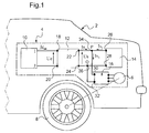
- the Figure 1 represents a vehicle 2 such as a motor vehicle.
- This vehicle 2 is equipped with a power supply system 4 of an electric motor 6 clean to drive in rotation of the driving wheels of the vehicle 2.
- a power supply system 4 of an electric motor 6 clean to drive in rotation of the driving wheels of the vehicle 2.
- To simplify the Figure 1 only one driving wheel 8 has been shown.
- a cable or a conductor is qualified "of power” if it is able to convey, without deteriorating, a power electric current.
- An electric power current is a current whose intensity is preferably greater than 25A or 100A.
- the pads 22 and 24 are also connected to the pads 30 and 32 via electrical branches 34 and 36.
- the inverter 16 generates a voltage and a three-phase power supply of the motor 6 from a DC voltage Us.
- the converter 12 generates the voltage Us from the voltage Ue delivered by the battery 10.
- the inverter 16 is therefore powered by the voltage Us imposed by the battery 14 and by the currents delivered by the converter 12 and by the battery 14.
- the converter 12 is in the form of a housing 40 shown in more detail on the Figure 2 .
- the set of electronic power components necessary to perform the conversion of the voltage Ue and the current in the voltage Us and the current Is is housed inside the housing 40. To simplify the illustration, these electronic power components are represented as a block 42.
- the outer contours of the housing 40 are delimited by walls 44.
- the walls 44 completely surround the components 42 to isolate them mechanically from the outside.
- these walls 44 are made of a conductive material connected to ground. They thus form a Faraday cage which prevents the propagation of the electromagnetic waves generated by the switching of the components 42 outside the housing 40.
- the walls 44 are equipped with a connector 48.
- the connector 48 comprises the connection pads 18, 20, 22 and 24.
- One of the walls 44 has an opening blocked by a printed circuit board 50.
- the card 50 therefore forms part of this wall and contributes to the mechanical insulation of the components 42 from the outside.
- the card 50 is fixed without any degree of freedom on the periphery of the opening. For example, it is fixed on the wall 44 by means of screws 52, 54.
- the card 50 has an outer face 55 facing the outside of the housing and an inner face 56 facing the inside of the housing. Plans external and internal electrical connection are etched respectively on the outer and inner faces 55 and 56. Typically, these power planes are copper. These planes are conductive tracks whose width and length are greater than 1 cm and preferably 2 cm. Here, each outer plane is of the same dimension as an inner plane disposed opposite it but on the other face of the card 50. These outer and inner planes are separated by a plate 58 made of electrically insulating.
- two outer planes 60 and 62 and the two corresponding inner planes 64 and 66 are represented on the figure 2 .
- the planes 60 and 64 belong to the connection pad 22.
- the planes 62 and 66 belong to the connection pad 18.
- the plane 60 is put directly and simultaneously in contact with two faces 68, 70, respectively, of lugs 72, 74.
- the lugs 72 and 74 form the distal portions, respectively, of power cables 76, 78.
- the cable 76 connects the pad 22 to the pad 26 of the battery 14.
- the cable 78 connects pad 22 to pad 30 of inverter 16.
- the lugs 72 and 74 are lugs crimped on the end of the cables 76 and 78.
- the lugs are made of a conductive material such as copper.
- Each lug 72, 74 comprises a through hole, respectively 80, 82 extending along an axis, respectively 84, 86, perpendicular to the faces 68 and 70. These holes 80 and 82 are intended to receive fixing screws.
- the pods 72 and 74 are arranged next to each other so that their respective faces 68 and 70 are directly and simultaneously supported on the plane 60.
- the faces 68 and 70 have a sufficiently large surface to allow the passage of the power electric current without causing deterioration of these pods 72 and 74.
- the faces 68 and 70 each have a length of more than one centimeter over a width of more than one centimeter.
- the length and the width of the plane 60 are sufficient to receive, next to one another, the pods 72 and 74.
- the length and the width of the plane 60 are both chosen to define a surface greater than the total of surfaces of the faces 68, 70.
- the plane 60 is connected to the plane 64 via sleepers made of electrically conductive material.
- Three sleepers 90, 92 and 94 are shown on the Figure 2 .
- Each crossbar 90, 92 and 94 extends perpendicularly to the faces 54 and 56.
- These crosspieces extend from the plane 60 to the plane 64.
- These crosspieces 90, 92 and 94 make it possible to ensure a reproducible and reliable electrical current flow through the time between the electronic components 42 and the plane 60 on which the lugs 72 and 74 rest. In particular, the passage of current through the sleepers does not depend on a clamping force or a surface condition.
- these sleepers are metallized holes.
- the number of these sleepers and the cross section of each of these sleepers are chosen as a function of the intensity of the power current that must pass from the plane 60 to the plane 64. More specifically, the number and cross section of the sleepers are chosen to limit the temperature rise.
- the card 50 is also equipped with a removable attachment mechanism, lugs 72 and 74 on the plane 60.
- through holes 96, 98 are made through the card 50. These through holes 96 and 98 s extend respectively along the axes 84 and 86. They pass right through the thickness of the card 50.
- a nut 100 is welded on the plane 64 around the opening of the hole 96.
- a nut 102 is welded on the plane 64 around the opening of the hole 98. These nuts 100 and 102 are intended to receive screws, respectively, 104 and 106.
- the screws 104 and 106 pass, respectively, the holes 80, 96 and 82, 98 to come to press the faces 68 and 70 of the lugs 72 and 74 against the plane 60.
- the screw 106 is shown in its assembled position.
- the screw 104 is shown in a disassembled position. In the disassembled position, the screw 104 has not yet been introduced through the holes 80 and 96 or referred to inside the nut 100.
- the screws and nuts are here made of an electrically conductive material such as copper or steel.
- the electrical power power supplied or distributed by the outer cables flows from the plane 60 to the plane 64 both through the crosspieces 90, 92 and 94 but also through the screws 104, 106 and nuts 100 and 102.
- the bolt 102 is also welded to an electrical conductor 110 which connects the plane 64 to the components 42.
- the pad 22 thus produced also fulfills the function of the bypass 34. Indeed, since the pods 72 and 74 are simultaneously brought into contact with the plane 60, they are connected to each other by the intermediate of this plan. Therefore, the use of a bypass mechanically independent of the housing 40 is avoided.
- the plane 62 is directly brought into electrical contact with a terminal 120 forming the distal end of a power cable 122 connected to the battery 10.
- the stud 18 used to connect the cable 122 to the components 42 is identical to the stud 22 to the except that the planes 62 and 66 are not designed to receive two lugs next to each other. This pad is not described here in detail.
- the connector 48 also includes a cover 130 for protecting the connection pads and lugs connected to these pads.
- this hood 130 has internal partitions 132 and 134 intended to electrically isolate the each other the pods of each of the power cables. These partitions make it possible to avoid the appearance of a short-circuit between two lugs in the event of the lug being incorrectly attached to the card 50.
- the design of the cover 130 and the partitions is such that it allows this isolation function.
- the cover 130 is fixed on the card 50 or on the wall 44 by any appropriate means.
- the Figure 3 represents the outer face 54 of the card 50.
- plans 140 and 150 are visible.
- the plane 140 is used for the realization of the stud 24.
- the plane 150 is used for the realization of the stud 20.
- the outer face of the card 50 is formed solely of the insulating material 58.
- Circles such as circles 90, 92 and 94 symbolize the position of the various sleepers that connect the outer planes to the inner planes.
- the Figure 4 represents the inner face 56 of the card 50.
- planes 160 and 162 are visible. These planes 160 and 162 are used to produce, respectively, the pads 22 and 18. These planes are of the same dimensions and arranged vis-à-vis the visible planes on the face 54.
- the plans 160 and 162 fulfill the same functions as the plans 64 and 66 and are therefore not described here in more detail.
- the face 56 comprises, in addition to the planes 64, 66, 160 and 162, a ground plane 164 connected to the walls 44 via a connection 166.
- This plane 164 is electrically isolated from the planes 64, 66, 160 and 162 through a strip of the insulating material 58.
- This plane 164 passes close to each of the planes 64, 66, 160 and 162 while maintaining with respect to these plans an isolation distance adapted to avoid the appearance of a direct short circuit between one of these planes 64, 66, 160 and 162 and the plane 164.
- Common mode filter capacitors 170 to 173 are soldered between the planes 64, 66, 160 and 162 and the plane 164 so as to allow the filtering of electromagnetic disturbances with a frequency greater than or equal to 10 MHz. More precisely, the capacitors 170 to 173 are soldered, part between the plane 164 and secondly, respectively, between the planes 64, 66, 160 and 162.
- capacitors 170 to 173 are surface-mounted components (SMD) and are therefore provided with metallized ends directly welded to the corresponding conductive planes.
- SMD surface-mounted components
- the positioning of these capacitors 170 to 173 as described herein allows an improvement in the efficiency of the common mode electromagnetic filtering.
- the capacitors are positioned very close to the connections between the outer cables and the ground plane by means of a minimum of wiring, which reduces the parasitic inductances caused by these cabling.
- the planes 64, 66, 160 and 162 are of large area, that is to say that their length and respective width are both greater than one centimeter. This allows a high frequency low impedance link to the capacitors 170 to 173. This gives a global parasitic inductance between each of the planes 64, 66, 160 and 162 and the plane 164 less than 10 nH. Therefore, the common-mode disturbance currents are derived towards the walls 44 of the casing 40 which functions as a Faraday cage by these decoupling capacitors up to frequencies greater than 10 MHz.
- the card 50 may be replaced by a printed circuit board having more than two layers in which are etched tracks.
- a printed circuit board having more than two layers in which are etched tracks.
- Such a card comprises at least one outer plane in direct contact with the lugs and at least one inner plane in direct contact with electrical conductors located inside the housing 40.
- this card comprises one or more intermediate layers housed between the outer and inner planes. Conductive tracks are etched in these intermediate layers which allow flexible and flexible connection of the outer and inner planes.
- the card 50 can be replaced by a printed circuit board having only a single layer in which are engraved all tracks made of conductive material and, including the power supply planes.
- the inner supply plane is omitted.
- a ground plane such as plane 164, is etched in this single layer and capacitors such as capacitors 170 to 173 are soldered as described with reference to FIG. Figure 4 to filter common mode electromagnetic disturbances.
- the lugs of the external cables can be fixed on the external planes without the use of nuts and bolts.
- the power cable lugs are directly soldered on the outside planes.
- the external cables can be used to bring the supply voltage or any other desired potential.
- Common mode filter capacitors do not need to be surface mounted. It may also be a capacitor equipped with tabs intended to be soldered by conventional welding.
- the protective cover can be made using a heat-shrinkable sheath arranged on the whole of the upper face 54 so as to mold each of the lugs and the upper face remaining free.
- the protective cover can also be made by molding an insulating material on the feed planes and the lugs of the upper face 54.
- the housing 40 may be equipped with a plurality of printed circuit boards disposed on different faces of this housing.
- the electrical conductor which connects, inside the housing 40, each pad to the components 42 is a power cable or a busbar capable of conveying the electric power current inside the housing.
- the ground plane is electrically independent of the walls 44 of the housing 40.
- the housing only comprises electronic components that are not electronic power components.
- the housing described also applies to the connection of external cables only adapted to convey currents of low intensities.
Landscapes
- Engineering & Computer Science (AREA)
- Microelectronics & Electronic Packaging (AREA)
- Shielding Devices Or Components To Electric Or Magnetic Fields (AREA)
- Multi-Conductor Connections (AREA)
- Mounting Of Printed Circuit Boards And The Like (AREA)
- Connection Or Junction Boxes (AREA)
- Coupling Device And Connection With Printed Circuit (AREA)
Claims (8)
- Elektronisches Leistungsgehäuse zur Versorgung eines Kraftfahrzeugelektromotors, das Folgendes umfasst:- elektronische Bauteile (42),- Wände (44), die diese elektronischen Bauteile mechanisch von der Außenseite isolieren,- mindestens einen elektrischen Verbindungkontakt (18, 20, 42, 24), der auf einer Außenseite einer dieser Wände angeordnet ist, um elektrisch an ein Kabel außerhalb des Gehäuses angeschlossen zu werden, wobei dieser elektrische Verbindungskontakt elektrisch an die elektronischen Bauteile (42), die im Inneren des Gehäuses platziert sind, angeschlossen ist,dadurch gekennzeichnet, dass dieser Verbindungskontakt Folgendes umfasst:- eine Leiterplattenkarte (50), die einen Teil der Wand (44) des Gehäuses bildet und von der eine Seite an dem Äußeren des Gehäuses exponiert ist, und mindestens eine äußere elektrische Anschlussfläche (60, 62, 140, 150), die auf dieser Seite graviert ist, um direkt mit dem externen Kabel in Kontakt gebracht zu werden, wobei diese Fläche elektrisch an elektronische Bauteile angeschlossen ist,- eine innere elektrische Anschlussfläche (64, 66, 160, 162), die auf eine innere Seite der Leiterplattenkarte, die im Inneren des Gehäuses exponiert ist, graviert ist, und- mehrere leitende Durchgänge (90, 92, 94), die fest mit einer Seite der äußeren elektrischen Anschlussfläche (60, 62) und der anderen Seite der inneren elektrischen Anschlussfläche (64, 66) verbunden sind, um sie ständig elektrisch anzuschließen.
- Gehäuse nach Anspruch 1, dadurch gekennzeichnet, dass der Verbindungskontakt Folgendes umfasst:- eine Massefläche (164), die auf die Leiterplattenkarte graviert ist, und- mindestens einen Filterkondensator (170-173) zum Gleichtaktfiltern, der zwischen der elektrischen Anschlussfläche und dieser Massefläche angeschlossen ist.
- Gehäuse nach Anspruch 2, wobei der Kondensator (170-173) ein auf der Oberfläche montierter Kondensator ist.
- Gehäuse nach einem der vorhergehenden Ansprüche, wobei die elektrischen Anschlussflächen (60, 62, 64, 66, 140, 150, 160, 162) mindestens 1 cm breit und mindestens 1 cm lang sind.
- Gehäuse nach einem der vorhergehenden Ansprüche, wobei der Verbindungskontakt einen Mechanismus (10, 102, 104, 106) zum abnehmbaren Befestigen des externen Kabels auf der externen elektrischen Anschlussfläche umfasst.
- Elektrischer Anschluss, der Folgendes umfasst:- mindestens ein externes Kabel (76, 78, 142), das in einem Kabelschuh (72, 74, 120) endet, der eine elektrische Kontaktfläche aufweist,- dadurch gekennzeichnet, dass dieser elektrische Anschluss ein Gehäuse (40) nach einem der vorhergehenden Ansprüche umfasst, wobei die äußere elektrische Anschlussfläche (60, 62, 140, 150) direkt auf der Kontaktfläche des Kabelschuhs aufliegt.
- Anschluss nach dem vorhergehenden Anspruch, wobei:- der Anschluss zwei externe Kabel (76, 78) umfasst, die dazu bestimmt sind, elektrisch an denselben Verbindungskontakt angeschlossen zu sein, wobei jedes externe Kabel in einem Kabelschuh (72, 74) endet, der eine elektrische Kontaktfläche aufweist, und- die Oberfläche der externen elektrischen Anschlussfläche (60) dieses Verbindungskontakts ausreichend ausgedehnt ist, damit die Kontaktflächen der Kabelschuhe dieser zwei externen Kabel direkt und gleichzeitig in Auflage nebeneinander auf dieser externen elektrischen Anschlussfläche sind.
- Fahrzeug, dadurch gekennzeichnet, dass es einen elektrischen Anschluss nach dem Anspruch 6 oder 7 umfasst.
Applications Claiming Priority (2)
| Application Number | Priority Date | Filing Date | Title |
|---|---|---|---|
| FR0901214A FR2943210B1 (fr) | 2009-03-16 | 2009-03-16 | Boitier, raccord electrique incorporant ce boitier et vehicule incorporant ce raccord |
| PCT/EP2010/053309 WO2010106027A1 (fr) | 2009-03-16 | 2010-03-15 | Boitier,raccord electrique incorporant ce boitier et vehicule incorporant ce raccord |
Publications (2)
| Publication Number | Publication Date |
|---|---|
| EP2409554A1 EP2409554A1 (de) | 2012-01-25 |
| EP2409554B1 true EP2409554B1 (de) | 2016-09-07 |
Family
ID=41060044
Family Applications (1)
| Application Number | Title | Priority Date | Filing Date |
|---|---|---|---|
| EP10708774.4A Active EP2409554B1 (de) | 2009-03-16 | 2010-03-15 | Gehäuse, elektrischer anschluss damit und fahrzeug mit dem anschluss |
Country Status (8)
| Country | Link |
|---|---|
| US (1) | US8398412B2 (de) |
| EP (1) | EP2409554B1 (de) |
| JP (1) | JP2012520658A (de) |
| KR (1) | KR20110137798A (de) |
| CN (1) | CN102369793B (de) |
| BR (1) | BRPI1008716A2 (de) |
| FR (1) | FR2943210B1 (de) |
| WO (1) | WO2010106027A1 (de) |
Families Citing this family (8)
| Publication number | Priority date | Publication date | Assignee | Title |
|---|---|---|---|---|
| US8858270B2 (en) * | 2011-01-25 | 2014-10-14 | The Gillette Company | Rechargeable battery pack including low-resistance battery-pack interconnect |
| GB2501667B (en) * | 2011-11-04 | 2016-03-09 | Control Tech Ltd | Earth busbar |
| FR2982374B1 (fr) * | 2011-11-04 | 2014-07-04 | Michelin Soc Tech | Dispositif de mesure de tensions dans une pile a combustible |
| JP2015076908A (ja) * | 2013-10-07 | 2015-04-20 | 矢崎総業株式会社 | 電気接続箱 |
| EP2905888A1 (de) | 2014-02-05 | 2015-08-12 | Grundfos Holding A/S | Stromrichter |
| DE102018206231B3 (de) | 2018-04-23 | 2019-09-19 | Triathlon Batterien Gmbh | Vorrichtung zum elektrischen Kontaktieren einer Leiterplatte an ein Batteriezellenverbundsystem und Einrichtung mit einer derartigen Vorrichtung und einem derartigen Batteriezellenverbundsystem |
| US11350526B2 (en) | 2019-09-27 | 2022-05-31 | Ge Aviation Systems, Llc | Reversible electronic card and method of implementation thereof |
| EP4344371B1 (de) * | 2022-09-22 | 2025-08-20 | Volvo Car Corporation | Elektromagnetische filteranordnung zur dämpfung elektromagnetischer störungen, schlagwundenanordnung, gehäuseanordnung und fahrzeug |
Family Cites Families (20)
| Publication number | Priority date | Publication date | Assignee | Title |
|---|---|---|---|---|
| US3836943A (en) * | 1973-05-29 | 1974-09-17 | Gamco Ind Inc | Electrical connector for coaxial cable |
| US3951490A (en) * | 1974-01-24 | 1976-04-20 | The Magnavox Company | Cable system distribution substation with novel center conductor seizure apparatus |
| US3989333A (en) * | 1975-12-18 | 1976-11-02 | Arvin Industries, Inc. | Cable television tap connector box |
| FR2606226B1 (fr) | 1986-11-05 | 1988-12-09 | Merlin Gerin | Convertisseur statique comportant un filtre de protection contre les perturbations haute frequence |
| JPS63300599A (ja) * | 1987-05-30 | 1988-12-07 | Fujitsu Ltd | 通信機器の電磁シ−ルド構造 |
| US4851609A (en) * | 1988-05-10 | 1989-07-25 | Prabhakara Reddy | Protective housing for an electrical device |
| JPH01289200A (ja) * | 1988-05-16 | 1989-11-21 | Hitachi Ltd | 電子装置 |
| JPH01317846A (ja) * | 1989-04-05 | 1989-12-22 | Nippon Denso Co Ltd | 車載用電子装置 |
| US6359331B1 (en) * | 1997-12-23 | 2002-03-19 | Ford Global Technologies, Inc. | High power switching module |
| DE10064969B4 (de) * | 2000-01-20 | 2007-11-15 | Heidelberger Druckmaschinen Ag | Filtervorrichtung für mindestens eine von außen an ein Gehäuse anzuschließende elektrische Leitung |
| US20020034088A1 (en) * | 2000-09-20 | 2002-03-21 | Scott Parkhill | Leadframe-based module DC bus design to reduce module inductance |
| FR2849346B1 (fr) * | 2002-12-20 | 2006-12-08 | Thales Sa | Boitier hyperfrequence a montage de surface et montage correspondant avec un circuit multicouche. |
| JP4142565B2 (ja) * | 2003-12-17 | 2008-09-03 | 矢崎総業株式会社 | 電気接続箱 |
| JP4410722B2 (ja) | 2005-05-06 | 2010-02-03 | 株式会社日立製作所 | 電源装置 |
| JP4531675B2 (ja) * | 2005-10-18 | 2010-08-25 | 矢崎総業株式会社 | 配索装置 |
| EP1777772B1 (de) | 2005-10-19 | 2007-11-07 | C.R.F. Società Consortile per Azioni | Vorrichtung zum Speichern von elektrischer Energie für die Versorgung von elektrischen Lasten mit hoher Priorität, insbesondere für Motorfahrzeuge |
| US7775578B2 (en) * | 2006-07-05 | 2010-08-17 | Intier Automotive Inc. | Removable power seat connector |
| US7993155B2 (en) * | 2008-09-19 | 2011-08-09 | Better Place GmbH | System for electrically connecting batteries to electric vehicles |
| DE102009051801A1 (de) * | 2008-11-03 | 2010-07-01 | Trw Vehicle Safety Systems Inc., Washington | Aktive Kopfstütze für einen Fahrzeugsitz |
| US20100285679A1 (en) * | 2009-05-05 | 2010-11-11 | Miller Ryan A | Spring boot |
-
2009
- 2009-03-16 FR FR0901214A patent/FR2943210B1/fr not_active Expired - Fee Related
-
2010
- 2010-03-15 CN CN201080012537.XA patent/CN102369793B/zh not_active Expired - Fee Related
- 2010-03-15 JP JP2012500208A patent/JP2012520658A/ja active Pending
- 2010-03-15 EP EP10708774.4A patent/EP2409554B1/de active Active
- 2010-03-15 WO PCT/EP2010/053309 patent/WO2010106027A1/fr not_active Ceased
- 2010-03-15 KR KR1020117024273A patent/KR20110137798A/ko not_active Ceased
- 2010-03-15 BR BRPI1008716A patent/BRPI1008716A2/pt not_active IP Right Cessation
- 2010-03-15 US US13/256,785 patent/US8398412B2/en not_active Expired - Fee Related
Also Published As
| Publication number | Publication date |
|---|---|
| US20120071041A1 (en) | 2012-03-22 |
| JP2012520658A (ja) | 2012-09-06 |
| FR2943210A1 (fr) | 2010-09-17 |
| US8398412B2 (en) | 2013-03-19 |
| BRPI1008716A2 (pt) | 2016-03-08 |
| WO2010106027A1 (fr) | 2010-09-23 |
| CN102369793A (zh) | 2012-03-07 |
| EP2409554A1 (de) | 2012-01-25 |
| KR20110137798A (ko) | 2011-12-23 |
| FR2943210B1 (fr) | 2011-04-29 |
| CN102369793B (zh) | 2015-06-03 |
Similar Documents
| Publication | Publication Date | Title |
|---|---|---|
| EP2409554B1 (de) | Gehäuse, elektrischer anschluss damit und fahrzeug mit dem anschluss | |
| EP2801245B1 (de) | Vorrichtung zur montage von kondensatoren für einen elektronischen wandler | |
| WO2012013641A1 (fr) | Batterie d'accumulateurs a conception et montage facilites | |
| EP3323175B1 (de) | An mehrere kabel mit schutz gegen schäden durch fremdkörper anschliessbare elektrische verbindungsvorrichtung | |
| FR3098078A1 (fr) | Circuit imprimé et procédé pour la mesure de la température dans un connecteur électrique de puissance | |
| WO2010097535A1 (fr) | Dispositif de liaison mecanique et electrique pour un cable coaxial transportant un signal haute frequence | |
| FR2589636A1 (fr) | Bloc connecteur amovible a utiliser dans un assemblage de connecteurs | |
| FR2567691A1 (fr) | Barre omnibus pour montage en surface | |
| FR3050878B1 (fr) | Barre de connexion electrique destinee a echanger de l'energie electrique entre un equipement electrique et un reseau electrique | |
| EP1912261A1 (de) | Elektrische Anschlussvorrichtung, insbesondere für elektrischen Sonnenkollektor | |
| EP3240157B1 (de) | Elektronischer filter zum filtern der energieeinspeiseleistung eines elektromotors | |
| EP1422799A1 (de) | Energieverteileranordnung für elektrische Geräte | |
| EP1120659A1 (de) | Elektrischer Energiezähler | |
| FR2662863A1 (fr) | Dispositif connecteur adaptateur de terminaison. | |
| FR2940528A1 (fr) | Composant electronique notamment capteur a effet hall | |
| EP0629108B1 (de) | Versorgungsverteilung-Busschiene für Komponentenunterlage, die Komponentenunterlage und Verteilungsbrücken zum Verbinden der Busschiene mit der Unterlage | |
| FR2828591A1 (fr) | Connecteur muni de contacts a serrage sur une paire de barres de bus | |
| EP3406001A1 (de) | Gehäuse für elektrischen anschluss von hochspannungskabeln | |
| FR2961356A1 (fr) | Connecteur | |
| EP1371113B1 (de) | Stromverbinder für eine gedruckte schaltung | |
| FR2928784A1 (fr) | Dispositif de raccordement electrique notamment pour panneau solaire electrique | |
| FR3058565A1 (fr) | Module electronique de puissance, equipement electrique et compresseur de suralimentation electrique comprenant un tel module electronique de puissance | |
| FR3161822A1 (fr) | Filtre CEM pour convertisseur de puissance et convertisseur de puissance | |
| FR3061365B1 (fr) | Procede d'assemblage d'un dispositif de distribution d'energie, cellule de mesure associee et ensemble conducteur de phase et cellule de mesure associe | |
| FR3143911A1 (fr) | Moyen de connexion électrique d’un module de puissance et d’une barre de connexion |
Legal Events
| Date | Code | Title | Description |
|---|---|---|---|
| PUAI | Public reference made under article 153(3) epc to a published international application that has entered the european phase |
Free format text: ORIGINAL CODE: 0009012 |
|
| 17P | Request for examination filed |
Effective date: 20110915 |
|
| AK | Designated contracting states |
Kind code of ref document: A1 Designated state(s): AT BE BG CH CY CZ DE DK EE ES FI FR GB GR HR HU IE IS IT LI LT LU LV MC MK MT NL NO PL PT RO SE SI SK SM TR |
|
| DAX | Request for extension of the european patent (deleted) | ||
| RAP1 | Party data changed (applicant data changed or rights of an application transferred) |
Owner name: COMMISSARIAT A L'ENERGIE ATOMIQUE |
|
| RAP1 | Party data changed (applicant data changed or rights of an application transferred) |
Owner name: COMMISSARIAT A L'ENERGIE ATOMIQUE ET AUX ENERGIES Owner name: PEUGEOT CITROEN AUTOMOBILES |
|
| 17Q | First examination report despatched |
Effective date: 20150827 |
|
| GRAP | Despatch of communication of intention to grant a patent |
Free format text: ORIGINAL CODE: EPIDOSNIGR1 |
|
| INTG | Intention to grant announced |
Effective date: 20160520 |
|
| GRAS | Grant fee paid |
Free format text: ORIGINAL CODE: EPIDOSNIGR3 |
|
| GRAA | (expected) grant |
Free format text: ORIGINAL CODE: 0009210 |
|
| AK | Designated contracting states |
Kind code of ref document: B1 Designated state(s): AT BE BG CH CY CZ DE DK EE ES FI FR GB GR HR HU IE IS IT LI LT LU LV MC MK MT NL NO PL PT RO SE SI SK SM TR |
|
| REG | Reference to a national code |
Ref country code: GB Ref legal event code: FG4D Free format text: NOT ENGLISH |
|
| REG | Reference to a national code |
Ref country code: CH Ref legal event code: EP |
|
| REG | Reference to a national code |
Ref country code: IE Ref legal event code: FG4D Free format text: LANGUAGE OF EP DOCUMENT: FRENCH |
|
| REG | Reference to a national code |
Ref country code: AT Ref legal event code: REF Ref document number: 827843 Country of ref document: AT Kind code of ref document: T Effective date: 20161015 |
|
| REG | Reference to a national code |
Ref country code: DE Ref legal event code: R096 Ref document number: 602010036170 Country of ref document: DE |
|
| REG | Reference to a national code |
Ref country code: LT Ref legal event code: MG4D |
|
| REG | Reference to a national code |
Ref country code: NL Ref legal event code: MP Effective date: 20160907 |
|
| PG25 | Lapsed in a contracting state [announced via postgrant information from national office to epo] |
Ref country code: LT Free format text: LAPSE BECAUSE OF FAILURE TO SUBMIT A TRANSLATION OF THE DESCRIPTION OR TO PAY THE FEE WITHIN THE PRESCRIBED TIME-LIMIT Effective date: 20160907 Ref country code: NO Free format text: LAPSE BECAUSE OF FAILURE TO SUBMIT A TRANSLATION OF THE DESCRIPTION OR TO PAY THE FEE WITHIN THE PRESCRIBED TIME-LIMIT Effective date: 20161207 Ref country code: FI Free format text: LAPSE BECAUSE OF FAILURE TO SUBMIT A TRANSLATION OF THE DESCRIPTION OR TO PAY THE FEE WITHIN THE PRESCRIBED TIME-LIMIT Effective date: 20160907 Ref country code: HR Free format text: LAPSE BECAUSE OF FAILURE TO SUBMIT A TRANSLATION OF THE DESCRIPTION OR TO PAY THE FEE WITHIN THE PRESCRIBED TIME-LIMIT Effective date: 20160907 |
|
| REG | Reference to a national code |
Ref country code: AT Ref legal event code: MK05 Ref document number: 827843 Country of ref document: AT Kind code of ref document: T Effective date: 20160907 |
|
| REG | Reference to a national code |
Ref country code: FR Ref legal event code: PLFP Year of fee payment: 8 |
|
| PG25 | Lapsed in a contracting state [announced via postgrant information from national office to epo] |
Ref country code: SE Free format text: LAPSE BECAUSE OF FAILURE TO SUBMIT A TRANSLATION OF THE DESCRIPTION OR TO PAY THE FEE WITHIN THE PRESCRIBED TIME-LIMIT Effective date: 20160907 Ref country code: ES Free format text: LAPSE BECAUSE OF FAILURE TO SUBMIT A TRANSLATION OF THE DESCRIPTION OR TO PAY THE FEE WITHIN THE PRESCRIBED TIME-LIMIT Effective date: 20160907 Ref country code: GR Free format text: LAPSE BECAUSE OF FAILURE TO SUBMIT A TRANSLATION OF THE DESCRIPTION OR TO PAY THE FEE WITHIN THE PRESCRIBED TIME-LIMIT Effective date: 20161208 Ref country code: LV Free format text: LAPSE BECAUSE OF FAILURE TO SUBMIT A TRANSLATION OF THE DESCRIPTION OR TO PAY THE FEE WITHIN THE PRESCRIBED TIME-LIMIT Effective date: 20160907 Ref country code: NL Free format text: LAPSE BECAUSE OF FAILURE TO SUBMIT A TRANSLATION OF THE DESCRIPTION OR TO PAY THE FEE WITHIN THE PRESCRIBED TIME-LIMIT Effective date: 20160907 |
|
| PG25 | Lapsed in a contracting state [announced via postgrant information from national office to epo] |
Ref country code: EE Free format text: LAPSE BECAUSE OF FAILURE TO SUBMIT A TRANSLATION OF THE DESCRIPTION OR TO PAY THE FEE WITHIN THE PRESCRIBED TIME-LIMIT Effective date: 20160907 Ref country code: RO Free format text: LAPSE BECAUSE OF FAILURE TO SUBMIT A TRANSLATION OF THE DESCRIPTION OR TO PAY THE FEE WITHIN THE PRESCRIBED TIME-LIMIT Effective date: 20160907 |
|
| PG25 | Lapsed in a contracting state [announced via postgrant information from national office to epo] |
Ref country code: PT Free format text: LAPSE BECAUSE OF FAILURE TO SUBMIT A TRANSLATION OF THE DESCRIPTION OR TO PAY THE FEE WITHIN THE PRESCRIBED TIME-LIMIT Effective date: 20170109 Ref country code: BG Free format text: LAPSE BECAUSE OF FAILURE TO SUBMIT A TRANSLATION OF THE DESCRIPTION OR TO PAY THE FEE WITHIN THE PRESCRIBED TIME-LIMIT Effective date: 20161207 Ref country code: AT Free format text: LAPSE BECAUSE OF FAILURE TO SUBMIT A TRANSLATION OF THE DESCRIPTION OR TO PAY THE FEE WITHIN THE PRESCRIBED TIME-LIMIT Effective date: 20160907 Ref country code: IS Free format text: LAPSE BECAUSE OF FAILURE TO SUBMIT A TRANSLATION OF THE DESCRIPTION OR TO PAY THE FEE WITHIN THE PRESCRIBED TIME-LIMIT Effective date: 20170107 Ref country code: PL Free format text: LAPSE BECAUSE OF FAILURE TO SUBMIT A TRANSLATION OF THE DESCRIPTION OR TO PAY THE FEE WITHIN THE PRESCRIBED TIME-LIMIT Effective date: 20160907 Ref country code: CZ Free format text: LAPSE BECAUSE OF FAILURE TO SUBMIT A TRANSLATION OF THE DESCRIPTION OR TO PAY THE FEE WITHIN THE PRESCRIBED TIME-LIMIT Effective date: 20160907 Ref country code: SK Free format text: LAPSE BECAUSE OF FAILURE TO SUBMIT A TRANSLATION OF THE DESCRIPTION OR TO PAY THE FEE WITHIN THE PRESCRIBED TIME-LIMIT Effective date: 20160907 Ref country code: SM Free format text: LAPSE BECAUSE OF FAILURE TO SUBMIT A TRANSLATION OF THE DESCRIPTION OR TO PAY THE FEE WITHIN THE PRESCRIBED TIME-LIMIT Effective date: 20160907 |
|
| REG | Reference to a national code |
Ref country code: DE Ref legal event code: R097 Ref document number: 602010036170 Country of ref document: DE |
|
| PG25 | Lapsed in a contracting state [announced via postgrant information from national office to epo] |
Ref country code: IT Free format text: LAPSE BECAUSE OF FAILURE TO SUBMIT A TRANSLATION OF THE DESCRIPTION OR TO PAY THE FEE WITHIN THE PRESCRIBED TIME-LIMIT Effective date: 20160907 |
|
| PLBE | No opposition filed within time limit |
Free format text: ORIGINAL CODE: 0009261 |
|
| STAA | Information on the status of an ep patent application or granted ep patent |
Free format text: STATUS: NO OPPOSITION FILED WITHIN TIME LIMIT |
|
| PG25 | Lapsed in a contracting state [announced via postgrant information from national office to epo] |
Ref country code: DK Free format text: LAPSE BECAUSE OF FAILURE TO SUBMIT A TRANSLATION OF THE DESCRIPTION OR TO PAY THE FEE WITHIN THE PRESCRIBED TIME-LIMIT Effective date: 20160907 |
|
| 26N | No opposition filed |
Effective date: 20170608 |
|
| PG25 | Lapsed in a contracting state [announced via postgrant information from national office to epo] |
Ref country code: SI Free format text: LAPSE BECAUSE OF FAILURE TO SUBMIT A TRANSLATION OF THE DESCRIPTION OR TO PAY THE FEE WITHIN THE PRESCRIBED TIME-LIMIT Effective date: 20160907 |
|
| REG | Reference to a national code |
Ref country code: CH Ref legal event code: PL |
|
| PG25 | Lapsed in a contracting state [announced via postgrant information from national office to epo] |
Ref country code: MC Free format text: LAPSE BECAUSE OF FAILURE TO SUBMIT A TRANSLATION OF THE DESCRIPTION OR TO PAY THE FEE WITHIN THE PRESCRIBED TIME-LIMIT Effective date: 20160907 |
|
| REG | Reference to a national code |
Ref country code: IE Ref legal event code: MM4A |
|
| PG25 | Lapsed in a contracting state [announced via postgrant information from national office to epo] |
Ref country code: LU Free format text: LAPSE BECAUSE OF NON-PAYMENT OF DUE FEES Effective date: 20170315 |
|
| REG | Reference to a national code |
Ref country code: FR Ref legal event code: PLFP Year of fee payment: 9 |
|
| PG25 | Lapsed in a contracting state [announced via postgrant information from national office to epo] |
Ref country code: CH Free format text: LAPSE BECAUSE OF NON-PAYMENT OF DUE FEES Effective date: 20170331 Ref country code: LI Free format text: LAPSE BECAUSE OF NON-PAYMENT OF DUE FEES Effective date: 20170331 Ref country code: IE Free format text: LAPSE BECAUSE OF NON-PAYMENT OF DUE FEES Effective date: 20170315 |
|
| REG | Reference to a national code |
Ref country code: BE Ref legal event code: MM Effective date: 20170331 |
|
| PG25 | Lapsed in a contracting state [announced via postgrant information from national office to epo] |
Ref country code: BE Free format text: LAPSE BECAUSE OF NON-PAYMENT OF DUE FEES Effective date: 20170331 |
|
| REG | Reference to a national code |
Ref country code: FR Ref legal event code: CA Effective date: 20180312 Ref country code: FR Ref legal event code: CD Owner name: PEUGEOT CITROEN AUTOMOBILES, FR Effective date: 20180312 Ref country code: FR Ref legal event code: CD Owner name: PEUGEOT CITROEN AUTOMOBILES SA, FR Effective date: 20180312 |
|
| PG25 | Lapsed in a contracting state [announced via postgrant information from national office to epo] |
Ref country code: MT Free format text: LAPSE BECAUSE OF FAILURE TO SUBMIT A TRANSLATION OF THE DESCRIPTION OR TO PAY THE FEE WITHIN THE PRESCRIBED TIME-LIMIT Effective date: 20160907 |
|
| PG25 | Lapsed in a contracting state [announced via postgrant information from national office to epo] |
Ref country code: HU Free format text: LAPSE BECAUSE OF FAILURE TO SUBMIT A TRANSLATION OF THE DESCRIPTION OR TO PAY THE FEE WITHIN THE PRESCRIBED TIME-LIMIT; INVALID AB INITIO Effective date: 20100315 |
|
| PG25 | Lapsed in a contracting state [announced via postgrant information from national office to epo] |
Ref country code: CY Free format text: LAPSE BECAUSE OF NON-PAYMENT OF DUE FEES Effective date: 20160907 |
|
| PG25 | Lapsed in a contracting state [announced via postgrant information from national office to epo] |
Ref country code: MK Free format text: LAPSE BECAUSE OF FAILURE TO SUBMIT A TRANSLATION OF THE DESCRIPTION OR TO PAY THE FEE WITHIN THE PRESCRIBED TIME-LIMIT Effective date: 20160907 |
|
| PG25 | Lapsed in a contracting state [announced via postgrant information from national office to epo] |
Ref country code: TR Free format text: LAPSE BECAUSE OF FAILURE TO SUBMIT A TRANSLATION OF THE DESCRIPTION OR TO PAY THE FEE WITHIN THE PRESCRIBED TIME-LIMIT Effective date: 20160907 |
|
| PGFP | Annual fee paid to national office [announced via postgrant information from national office to epo] |
Ref country code: DE Payment date: 20250218 Year of fee payment: 16 |
|
| PGFP | Annual fee paid to national office [announced via postgrant information from national office to epo] |
Ref country code: FR Payment date: 20250218 Year of fee payment: 16 |
|
| PGFP | Annual fee paid to national office [announced via postgrant information from national office to epo] |
Ref country code: GB Payment date: 20250220 Year of fee payment: 16 |