EP2409554B1 - Housing, electrical connector with said housing and vehicle with said connector - Google Patents
Housing, electrical connector with said housing and vehicle with said connector Download PDFInfo
- Publication number
- EP2409554B1 EP2409554B1 EP10708774.4A EP10708774A EP2409554B1 EP 2409554 B1 EP2409554 B1 EP 2409554B1 EP 10708774 A EP10708774 A EP 10708774A EP 2409554 B1 EP2409554 B1 EP 2409554B1
- Authority
- EP
- European Patent Office
- Prior art keywords
- housing
- exterior
- plane
- electrical connection
- electrical
- Prior art date
- Legal status (The legal status is an assumption and is not a legal conclusion. Google has not performed a legal analysis and makes no representation as to the accuracy of the status listed.)
- Active
Links
Images


Classifications
-
- H—ELECTRICITY
- H05—ELECTRIC TECHNIQUES NOT OTHERWISE PROVIDED FOR
- H05K—PRINTED CIRCUITS; CASINGS OR CONSTRUCTIONAL DETAILS OF ELECTRIC APPARATUS; MANUFACTURE OF ASSEMBLAGES OF ELECTRICAL COMPONENTS
- H05K7/00—Constructional details common to different types of electric apparatus
- H05K7/14—Mounting supporting structure in casing or on frame or rack
- H05K7/1422—Printed circuit boards receptacles, e.g. stacked structures, electronic circuit modules or box like frames
- H05K7/1427—Housings
- H05K7/1432—Housings specially adapted for power drive units or power converters
- H05K7/14322—Housings specially adapted for power drive units or power converters wherein the control and power circuits of a power converter are arranged within the same casing
Definitions
- the invention relates to a housing, an electrical connection made using this housing and a vehicle equipped with this electrical connection.
- the metal base passes right through the wall, while being electrically insulated design thereof. Inside the housing, it is electrically connected to an electrical conductor that electrically connects the screw to the electronic components.
- the screw protrudes outwardly of the housing perpendicularly to the outer face. It is mechanically secured to the metal base. It is generally metallic (electrical conductor), electrically connected to the metal base and also isolated from the wall of the housing.
- the metal base has on its outer face a bearing surface perpendicular to the axis of the screw.
- the cable located outside the housing terminates in a terminal adapted to be plugged onto the housing screw and come to rest on this bearing surface.
- the nut then makes it possible to fix the lug on the screw and to establish the electrical contact between the lug and the metal base so with the electronic components in the case.
- Such boxes are known to US2002 / 0126465 A1 and US6359331B1 .
- the contact area between the lug and the bearing surface must be important to limit the electrical resistance at the interface between these two elements. This therefore often results in a cumbersome connector that protrudes well beyond the outer face of the housing.
- the invention aims to remedy at least one of these disadvantages by providing an improved housing.
- the outer plane (for example the power connection) constitutes an electrical contact surface of the connection pad with the outer cable without the congestion of the connectors in a direction perpendicular to the outer face has been increased. This therefore allows for a connection pad whose size in a direction perpendicular to the outer face of the housing is reduced.
- the connector thus produced is particularly simple and inexpensive.
- Embodiments of this housing may include one or more of the features of the dependent claims.
- the invention also relates to an electrical connection according to claim 7.
- Embodiments of this coupling may include the feature of claim 8.
- the invention also relates to a vehicle equipped with the electrical connection above.
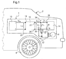
- the Figure 1 represents a vehicle 2 such as a motor vehicle.
- This vehicle 2 is equipped with a power supply system 4 of an electric motor 6 clean to drive in rotation of the driving wheels of the vehicle 2.
- a power supply system 4 of an electric motor 6 clean to drive in rotation of the driving wheels of the vehicle 2.
- To simplify the Figure 1 only one driving wheel 8 has been shown.
- a cable or a conductor is qualified "of power” if it is able to convey, without deteriorating, a power electric current.
- An electric power current is a current whose intensity is preferably greater than 25A or 100A.
- the pads 22 and 24 are also connected to the pads 30 and 32 via electrical branches 34 and 36.
- the inverter 16 generates a voltage and a three-phase power supply of the motor 6 from a DC voltage Us.
- the converter 12 generates the voltage Us from the voltage Ue delivered by the battery 10.
- the inverter 16 is therefore powered by the voltage Us imposed by the battery 14 and by the currents delivered by the converter 12 and by the battery 14.
- the converter 12 is in the form of a housing 40 shown in more detail on the Figure 2 .
- the set of electronic power components necessary to perform the conversion of the voltage Ue and the current in the voltage Us and the current Is is housed inside the housing 40. To simplify the illustration, these electronic power components are represented as a block 42.
- the outer contours of the housing 40 are delimited by walls 44.
- the walls 44 completely surround the components 42 to isolate them mechanically from the outside.
- these walls 44 are made of a conductive material connected to ground. They thus form a Faraday cage which prevents the propagation of the electromagnetic waves generated by the switching of the components 42 outside the housing 40.
- the walls 44 are equipped with a connector 48.
- the connector 48 comprises the connection pads 18, 20, 22 and 24.
- One of the walls 44 has an opening blocked by a printed circuit board 50.
- the card 50 therefore forms part of this wall and contributes to the mechanical insulation of the components 42 from the outside.
- the card 50 is fixed without any degree of freedom on the periphery of the opening. For example, it is fixed on the wall 44 by means of screws 52, 54.
- the card 50 has an outer face 55 facing the outside of the housing and an inner face 56 facing the inside of the housing. Plans external and internal electrical connection are etched respectively on the outer and inner faces 55 and 56. Typically, these power planes are copper. These planes are conductive tracks whose width and length are greater than 1 cm and preferably 2 cm. Here, each outer plane is of the same dimension as an inner plane disposed opposite it but on the other face of the card 50. These outer and inner planes are separated by a plate 58 made of electrically insulating.
- two outer planes 60 and 62 and the two corresponding inner planes 64 and 66 are represented on the figure 2 .
- the planes 60 and 64 belong to the connection pad 22.
- the planes 62 and 66 belong to the connection pad 18.
- the plane 60 is put directly and simultaneously in contact with two faces 68, 70, respectively, of lugs 72, 74.
- the lugs 72 and 74 form the distal portions, respectively, of power cables 76, 78.
- the cable 76 connects the pad 22 to the pad 26 of the battery 14.
- the cable 78 connects pad 22 to pad 30 of inverter 16.
- the lugs 72 and 74 are lugs crimped on the end of the cables 76 and 78.
- the lugs are made of a conductive material such as copper.
- Each lug 72, 74 comprises a through hole, respectively 80, 82 extending along an axis, respectively 84, 86, perpendicular to the faces 68 and 70. These holes 80 and 82 are intended to receive fixing screws.
- the pods 72 and 74 are arranged next to each other so that their respective faces 68 and 70 are directly and simultaneously supported on the plane 60.
- the faces 68 and 70 have a sufficiently large surface to allow the passage of the power electric current without causing deterioration of these pods 72 and 74.
- the faces 68 and 70 each have a length of more than one centimeter over a width of more than one centimeter.
- the length and the width of the plane 60 are sufficient to receive, next to one another, the pods 72 and 74.
- the length and the width of the plane 60 are both chosen to define a surface greater than the total of surfaces of the faces 68, 70.
- the plane 60 is connected to the plane 64 via sleepers made of electrically conductive material.
- Three sleepers 90, 92 and 94 are shown on the Figure 2 .
- Each crossbar 90, 92 and 94 extends perpendicularly to the faces 54 and 56.
- These crosspieces extend from the plane 60 to the plane 64.
- These crosspieces 90, 92 and 94 make it possible to ensure a reproducible and reliable electrical current flow through the time between the electronic components 42 and the plane 60 on which the lugs 72 and 74 rest. In particular, the passage of current through the sleepers does not depend on a clamping force or a surface condition.
- these sleepers are metallized holes.
- the number of these sleepers and the cross section of each of these sleepers are chosen as a function of the intensity of the power current that must pass from the plane 60 to the plane 64. More specifically, the number and cross section of the sleepers are chosen to limit the temperature rise.
- the card 50 is also equipped with a removable attachment mechanism, lugs 72 and 74 on the plane 60.
- through holes 96, 98 are made through the card 50. These through holes 96 and 98 s extend respectively along the axes 84 and 86. They pass right through the thickness of the card 50.
- a nut 100 is welded on the plane 64 around the opening of the hole 96.
- a nut 102 is welded on the plane 64 around the opening of the hole 98. These nuts 100 and 102 are intended to receive screws, respectively, 104 and 106.
- the screws 104 and 106 pass, respectively, the holes 80, 96 and 82, 98 to come to press the faces 68 and 70 of the lugs 72 and 74 against the plane 60.
- the screw 106 is shown in its assembled position.
- the screw 104 is shown in a disassembled position. In the disassembled position, the screw 104 has not yet been introduced through the holes 80 and 96 or referred to inside the nut 100.
- the screws and nuts are here made of an electrically conductive material such as copper or steel.
- the electrical power power supplied or distributed by the outer cables flows from the plane 60 to the plane 64 both through the crosspieces 90, 92 and 94 but also through the screws 104, 106 and nuts 100 and 102.
- the bolt 102 is also welded to an electrical conductor 110 which connects the plane 64 to the components 42.
- the pad 22 thus produced also fulfills the function of the bypass 34. Indeed, since the pods 72 and 74 are simultaneously brought into contact with the plane 60, they are connected to each other by the intermediate of this plan. Therefore, the use of a bypass mechanically independent of the housing 40 is avoided.
- the plane 62 is directly brought into electrical contact with a terminal 120 forming the distal end of a power cable 122 connected to the battery 10.
- the stud 18 used to connect the cable 122 to the components 42 is identical to the stud 22 to the except that the planes 62 and 66 are not designed to receive two lugs next to each other. This pad is not described here in detail.
- the connector 48 also includes a cover 130 for protecting the connection pads and lugs connected to these pads.
- this hood 130 has internal partitions 132 and 134 intended to electrically isolate the each other the pods of each of the power cables. These partitions make it possible to avoid the appearance of a short-circuit between two lugs in the event of the lug being incorrectly attached to the card 50.
- the design of the cover 130 and the partitions is such that it allows this isolation function.
- the cover 130 is fixed on the card 50 or on the wall 44 by any appropriate means.
- the Figure 3 represents the outer face 54 of the card 50.
- plans 140 and 150 are visible.
- the plane 140 is used for the realization of the stud 24.
- the plane 150 is used for the realization of the stud 20.
- the outer face of the card 50 is formed solely of the insulating material 58.
- Circles such as circles 90, 92 and 94 symbolize the position of the various sleepers that connect the outer planes to the inner planes.
- the Figure 4 represents the inner face 56 of the card 50.
- planes 160 and 162 are visible. These planes 160 and 162 are used to produce, respectively, the pads 22 and 18. These planes are of the same dimensions and arranged vis-à-vis the visible planes on the face 54.
- the plans 160 and 162 fulfill the same functions as the plans 64 and 66 and are therefore not described here in more detail.
- the face 56 comprises, in addition to the planes 64, 66, 160 and 162, a ground plane 164 connected to the walls 44 via a connection 166.
- This plane 164 is electrically isolated from the planes 64, 66, 160 and 162 through a strip of the insulating material 58.
- This plane 164 passes close to each of the planes 64, 66, 160 and 162 while maintaining with respect to these plans an isolation distance adapted to avoid the appearance of a direct short circuit between one of these planes 64, 66, 160 and 162 and the plane 164.
- Common mode filter capacitors 170 to 173 are soldered between the planes 64, 66, 160 and 162 and the plane 164 so as to allow the filtering of electromagnetic disturbances with a frequency greater than or equal to 10 MHz. More precisely, the capacitors 170 to 173 are soldered, part between the plane 164 and secondly, respectively, between the planes 64, 66, 160 and 162.
- capacitors 170 to 173 are surface-mounted components (SMD) and are therefore provided with metallized ends directly welded to the corresponding conductive planes.
- SMD surface-mounted components
- the positioning of these capacitors 170 to 173 as described herein allows an improvement in the efficiency of the common mode electromagnetic filtering.
- the capacitors are positioned very close to the connections between the outer cables and the ground plane by means of a minimum of wiring, which reduces the parasitic inductances caused by these cabling.
- the planes 64, 66, 160 and 162 are of large area, that is to say that their length and respective width are both greater than one centimeter. This allows a high frequency low impedance link to the capacitors 170 to 173. This gives a global parasitic inductance between each of the planes 64, 66, 160 and 162 and the plane 164 less than 10 nH. Therefore, the common-mode disturbance currents are derived towards the walls 44 of the casing 40 which functions as a Faraday cage by these decoupling capacitors up to frequencies greater than 10 MHz.
- the card 50 may be replaced by a printed circuit board having more than two layers in which are etched tracks.
- a printed circuit board having more than two layers in which are etched tracks.
- Such a card comprises at least one outer plane in direct contact with the lugs and at least one inner plane in direct contact with electrical conductors located inside the housing 40.
- this card comprises one or more intermediate layers housed between the outer and inner planes. Conductive tracks are etched in these intermediate layers which allow flexible and flexible connection of the outer and inner planes.
- the card 50 can be replaced by a printed circuit board having only a single layer in which are engraved all tracks made of conductive material and, including the power supply planes.
- the inner supply plane is omitted.
- a ground plane such as plane 164, is etched in this single layer and capacitors such as capacitors 170 to 173 are soldered as described with reference to FIG. Figure 4 to filter common mode electromagnetic disturbances.
- the lugs of the external cables can be fixed on the external planes without the use of nuts and bolts.
- the power cable lugs are directly soldered on the outside planes.
- the external cables can be used to bring the supply voltage or any other desired potential.
- Common mode filter capacitors do not need to be surface mounted. It may also be a capacitor equipped with tabs intended to be soldered by conventional welding.
- the protective cover can be made using a heat-shrinkable sheath arranged on the whole of the upper face 54 so as to mold each of the lugs and the upper face remaining free.
- the protective cover can also be made by molding an insulating material on the feed planes and the lugs of the upper face 54.
- the housing 40 may be equipped with a plurality of printed circuit boards disposed on different faces of this housing.
- the electrical conductor which connects, inside the housing 40, each pad to the components 42 is a power cable or a busbar capable of conveying the electric power current inside the housing.
- the ground plane is electrically independent of the walls 44 of the housing 40.
- the housing only comprises electronic components that are not electronic power components.
- the housing described also applies to the connection of external cables only adapted to convey currents of low intensities.
Description
L'invention concerne un boîtier, un raccord électrique réalisé à l'aide de ce boîtier et un véhicule équipé de ce raccord électrique.The invention relates to a housing, an electrical connection made using this housing and a vehicle equipped with this electrical connection.
Des boîtiers connus comportent :
- des composants électroniques,
- des parois isolant mécaniquement ces composants électroniques de l'extérieur,
- au moins un plot de connexion électrique disposé sur une face extérieure d'une de ces parois pour être raccordé électriquement à un ou plusieurs câbles ou un autre type de liaison électrique (barre, plaque, ...) extérieurs au boîtier, ce plot de connexion étant électriquement raccordé aux composants électroniques placés à l'intérieur du boîtier.
- electronic components,
- mechanically insulating walls of these electronic components from the outside,
- at least one electrical connection pad disposed on an outer face of one of these walls to be electrically connected to one or more cables or another type of electrical connection (bar, plate, ...) outside the housing, this stud of connection being electrically connected to the electronic components placed inside the housing.
Dans les boîtiers connus, ce plot de connexion peut se présenter sous différentes formes :
- par exemple sous la forme d'une broche d'un connecteur. Un même connecteur peut suivant le besoin regrouper plusieurs plots de connexion isolés les uns des autres. Cette méthode exige un connecteur en deux parties, une partie fixée sur la face de la paroi du boîtier et une partie mobile solidaire du câble extérieur au boîtier. Ce principe a comme avantage d'entraîner un degré élevé de facilité et de fiabilité dans les opérations de connexions et de déconnexions. Par contre, il a comme inconvénient d'être très volumineux et très coûteux, surtout dans le cas d'applications à des courants élevés (supérieurs à une dizaine d'ampères).
- par exemple sous la forme d'une vis, d'un écrou et d'une embase métallique, en général en laiton ou en cuivre, permettant au courant électrique de traverser la paroi du boîtier.
- for example in the form of a pin of a connector. The same connector may as required group several connection pads isolated from each other. This method requires a connector in two parts, a part fixed on the face of the wall of the housing and a movable part integral with the outer cable to the housing. This principle has the advantage of resulting in a high degree of ease and reliability in the operations of connections and disconnections. On the other hand, it has the drawback of being very bulky and very expensive, especially in the case of applications with high currents (greater than about ten amperes).
- for example in the form of a screw, a nut and a metal base, usually brass or copper, allowing the electric current to pass through the wall of the housing.
L'embase métallique traverse de part en part la paroi, tout en étant par conception isolée électriquement de celle-ci. A l'intérieur du boîtier, elle est électriquement raccordée à un conducteur électrique qui raccorde électriquement cette vis aux composants électroniques. La vis fait saillie vers l'extérieur du boîtier perpendiculairement à la face extérieure. Elle est mécaniquement solidaire de l'embase métallique. Elle est en général métallique (conducteur électrique), reliée électriquement à l'embase métallique et également isolée de la paroi du boîtier.
L'embase métallique présente sur sa face extérieure une surface d'appui perpendiculaire à l'axe de la vis.The metal base passes right through the wall, while being electrically insulated design thereof. Inside the housing, it is electrically connected to an electrical conductor that electrically connects the screw to the electronic components. The screw protrudes outwardly of the housing perpendicularly to the outer face. It is mechanically secured to the metal base. It is generally metallic (electrical conductor), electrically connected to the metal base and also isolated from the wall of the housing.
The metal base has on its outer face a bearing surface perpendicular to the axis of the screw.
Le câble situé à l'extérieur du boîtier se termine par une cosse apte à être embrochée sur la vis du boîtier et venir s'appuyer sur cette surface d'appui. L'écrou permet alors de fixer la cosse sur la vis et d'établir le contact électrique entre la cosse et l'embase métallique donc avec les composants électroniques dans le boîtier. De tels boîtiers sont connus de
La surface de contact entre la cosse et la surface d'appui doit être importante pour limiter la résistance électrique à l'interface entre ces deux éléments. Cela se traduit donc souvent par une connectique encombrante qui fait saillie bien au-delà de la face extérieure du boîtier.The contact area between the lug and the bearing surface must be important to limit the electrical resistance at the interface between these two elements. This therefore often results in a cumbersome connector that protrudes well beyond the outer face of the housing.
Par ailleurs, un contact électrique avec la vis s'établit par l'intermédiaire de l'écrou, de la vis et de leurs filetages. Il existe donc également ce chemin de passage pour le courant. Cette résistance de câblage est fonction du couple de serrage, des états de surface de la vis et de l'écrou et de l'état de corrosion, Le contact électrique sera donc peu reproductible, et donc une source de panne ou de dysfonctionnement susceptible d'évoluer défavorablement dans le temps.In addition, an electrical contact with the screw is established via the nut, the screw and their threads. There is also this pathway for the current. This wiring resistance is a function of the tightening torque, the surface conditions of the screw and the nut and the state of corrosion, the electrical contact will be little reproducible, and therefore a source of failure or malfunction likely to unfavorably evolve over time.
L'invention vise à remédier à au moins l'un de ces inconvénients en proposant un boîtier amélioré.The invention aims to remedy at least one of these disadvantages by providing an improved housing.
Elle a donc pour objet un boîtier conforme à la revendication 1.It therefore relates to a housing according to claim 1.
Dans le boîtier ci-dessus, le plan extérieur (par exemple la connexion d'alimentation) constitue une surface de contact électrique du plot de connexion avec le câble extérieur sans que l'encombrement de la connectique dans une direction perpendiculaire à la face extérieure ait été augmenté. Cela permet donc de réaliser un plot de connexion dont l'encombrement dans une direction perpendiculaire à la face extérieure du boîtier est réduit.In the above housing, the outer plane (for example the power connection) constitutes an electrical contact surface of the connection pad with the outer cable without the congestion of the connectors in a direction perpendicular to the outer face has been increased. This therefore allows for a connection pad whose size in a direction perpendicular to the outer face of the housing is reduced.
De plus, la connectique ainsi réalisée est particulièrement simple et peu onéreuse.In addition, the connector thus produced is particularly simple and inexpensive.
Les modes de réalisation de ce boîtier, peuvent comporter une ou plusieurs des caracteristiques des revendications dépendantes.Embodiments of this housing may include one or more of the features of the dependent claims.
Ces modes de réalisation du boîtier présentent en outre les avantages suivants :
- le positionnement d'un condensateur entre le plan d'alimentation et un plan de masse gravé sur la même carte de circuit imprimé permet de limiter les inductances parasites de câblage de ce condensateur, ce qui permet en fin de compte d'améliorer la filtration électromagnétique du mode commun ;
- utiliser un condensateur monté en surface permet de décroître encore plus les inductances parasites de câblage et donc d'améliorer encore plus la filtration électromagnétique du mode commun dans le but de contribuer au bon comportement du boîtier dans le domaine de la compatibilité électromagnétique (CEM);
- l'utilisation de plusieurs traverses conductrices raccordant les plans extérieur et intérieur permes d'assurer un passage de courant reproductible et fiable dans le temps qui est peu dépendant d'une force de serrage :
- l'utilisation de plan dont les surfaces sont supérieures au cm2 permet d'obtenir des liaisons haute fréquence de faible impédance vers le ou les condensateurs de filtrage de mode commun ;
- l'utilisation d'un mécanisme de fixation amovible permet le montage et le démontage réversibles du câble extérieur.
- the positioning of a capacitor between the power plane and a ground plane engraved on the same printed circuit board makes it possible to limit the parasitic inductances of the wiring of this capacitor, which ultimately makes it possible to improve the electromagnetic filtration common mode;
- using a capacitor mounted on the surface makes it possible to further reduce parasitic wiring inductances and thus to further improve the common-mode electromagnetic filtration in order to contribute to the good behavior of the housing in the field of electromagnetic compatibility (EMC);
- the use of several conductive ties connecting the outer and inner planes permes ensure a reproducible current flow and reliable over time that is not dependent on a clamping force:
- the use of plan whose surfaces are greater than cm 2 makes it possible to obtain high frequency links of low impedance towards the common mode filtering capacitor (s);
- the use of a removable attachment mechanism allows the reversible assembly and disassembly of the outer cable.
L'invention a également pour objet un raccord électrique conforme à la revendication 7.The invention also relates to an electrical connection according to claim 7.
Les modes de réalisation de ce raccord peuvent comporter la caractéristique de la revendication 8.Embodiments of this coupling may include the feature of claim 8.
Ce mode de réalisation du raccord électrique présente en outre l'avantage suivant :
- l a disposition des cosses des câbles extérieurs les unes à côté des autres permet de décroître l'épaisseur de la connectique dans la direction perpendiculaire à la face extérieure de la carte de circuit imprimé.
- the arrangement of the outer cable lugs next to one another makes it possible to decrease the thickness of the connectors in the direction perpendicular to the outer face of the printed circuit board.
L'invention a également pour objet un véhicule équipé du raccord électrique ci-dessus.The invention also relates to a vehicle equipped with the electrical connection above.
L'invention sera mieux comprise à la lecture de la description qui va suivre, donnée uniquement à titre d'exemple non limitatif et faite en se référant aux dessins sur lesquels :
- la
Figure 1 est une illustration schématique d'un véhicule équipé d'un boîtier électronique de puissance, - la
Figure 2 est une illustration schématique et en coupe de la connectique du boîtier électronique de laFigure 1 , - les
Figures 3 et 4 sont des illustrations en vue de dessus et en vue de dessous d'une carte de circuit imprimé utilisée dans la connectique de laFigure 2 .
- the
Figure 1 is a schematic illustration of a vehicle equipped with an electronic power unit, - the
Figure 2 is a schematic illustration in section of the connection of the electronic box of theFigure 1 , - the
Figures 3 and 4 are illustrations in top view and in bottom view of a printed circuit board used in the connectors of theFigure 2 .
Dans ces figures, les mêmes références sont utilisées pour désigner les mêmes éléments.In these figures, the same references are used to designate the same elements.
Dans la suite de cette description, les caractéristiques et fonctions bien connues de l'homme du métier ne sont pas décrites en détails.In the rest of this description, the features and functions well known to those skilled in the art are not described in detail.
La
Le système 4 comprend :
une pile 10 à combustible propre à générer un courant d'intensité le sous une tension appelée Ue,- un convertisseur continu -
continu 12 dont des plots 18, 20 de connexion sont directement raccordés électriquement à lapile 10, une batterie 14 électrochimique dont des plots 26, 28 de connexion sont directement raccordés électriquement à des plots 22, 24 de connexion du convertisseur 12, etun onduleur 16 dont des plots 30, 32 de connexion sont également directement raccordés électriquement aux plots 22, 24 du convertisseur 12.
- a
fuel cell 10 capable of generating a current of intensity at a voltage called Ue, - a DC-
DC converter 12 whoseconnection pads battery 10, - an
electrochemical battery 14 having connectingpads connection pads converter 12, and - an
inverter 16 whosepads pads converter 12.
Par la suite, à défaut d'indication contraire, lorsqu'on indique que deux éléments sont raccordés entre eux, il s'agit d'un raccordement électrique.Subsequently, unless otherwise indicated, when indicating that two elements are connected together, it is an electrical connection.
De plus, lorsque l'on indique que ces deux éléments sont « directement » raccordés l'un à l'autre, cela signifie que la connexion électrique est réalisée sans passer par l'intermédiaire d'autres charges électriques. Typiquement, cela correspond à une liaison électrique directe réalisée à l'aide de conducteurs électriques dont la résistance linéique est très inférieure à 1Ω/m lorsqu'ils sont traversés par un courant continu.Moreover, when it is indicated that these two elements are "directly" connected to each other, this means that the electrical connection is made without passing through other electrical charges. Typically, this corresponds to a direct electrical connection made using electrical conductors whose linear resistance is much lower than 1Ω / m when traversed by a direct current.
Ici, un câble ou un conducteur est qualifié « de puissance » s'il est apte à véhiculer, sans se détériorer, un courant électrique de puissance. Un courant électrique de puissance est un courant dont l'intensité est, de préférence, supérieure à 25A ou 100A.Here, a cable or a conductor is qualified "of power" if it is able to convey, without deteriorating, a power electric current. An electric power current is a current whose intensity is preferably greater than 25A or 100A.
Les plots 22 et 24 sont également raccordés aux plots 30 et 32 par l'intermédiaire de dérivations électriques 34 et 36.The
L'onduleur 16 génère une tension et un courant triphasé d'alimentation du moteur 6 à partir d'une tension continue Us.The
Le convertisseur 12 génère la tension Us à partir de la tension Ue délivrée par la pile 10.The
L'onduleur 16 est donc alimenté par la tension Us imposé par la batterie 14 et par les courants délivrés par le convertisseur 12 et par la batterie 14.The
Le convertisseur 12 se présente sous la forme d'un boîtier 40 représenté plus en détail sur la
L'ensemble des composants électroniques de puissance nécessaires pour réaliser la conversion de la tension Ue et du courant le en la tension Us et le courant Is est logé à l'intérieur du boîtier 40. Pour simplifier l'illustration, ces composants électroniques de puissance sont représentés sous la forme d'un bloc 42.The set of electronic power components necessary to perform the conversion of the voltage Ue and the current in the voltage Us and the current Is is housed inside the
Les contours extérieurs du boîtier 40 sont délimités par des parois 44. Les parois 44 entourent complètement les composants 42 pour les isoler mécaniquement de l'extérieur. Ici, ces parois 44 sont réalisées dans un matériau conducteur raccordé à la masse. Elles forment donc une cage de Faraday qui empêche la propagation des ondes électromagnétiques générées par la commutation des composants 42 à l'extérieur du boîtier 40.The outer contours of the
Les parois 44 sont équipées d'une connectique 48. La connectique 48 comprend les plots de connexion 18, 20, 22 et 24.The
Pour simplifier la
L'une des parois 44 présente une ouverture bouchée par une carte 50 de circuit imprimé. La carte 50 forme donc une partie de cette paroi et participe à l'isolation mécanique des composants 42 de l'extérieur. La carte 50 est fixée sans aucun degré de liberté sur le pourtour de l'ouverture. Par exemple, elle est fixée sur la paroi 44 à l'aide de vis 52, 54.One of the
La carte 50 présente une face extérieure 55 tournée vers l'extérieur du boîtier et une face intérieure 56 tournée vers l'intérieur du boîtier. Des plans extérieurs et intérieurs de connexion électrique sont gravés, respectivement, sur les faces extérieure et intérieure 55 et 56. Typiquement, ces plans d'alimentation sont en cuivre. Ces plans sont des pistes conductrices dont la largeur et la longueur sont supérieures à 1 cm et, de préférence, à 2cm. Ici, chaque plan extérieur est de même dimension qu'un plan intérieur disposé en vis-à-vis de celui-ci mais sur l'autre face de la carte 50. Ces plans extérieurs et intérieurs sont séparés par une plaque 58 en matériau électriquement isolant.The
A titre d'illustration, deux plans extérieurs 60 et 62 et les deux plans intérieurs 64 et 66 correspondantes sont représentés sur la
Le plan 60 est mis directement et simultanément en contact avec deux faces 68, 70, respectivement, de cosses 72, 74. Les cosses 72 et 74 forment les parties distales, respectivement, de câbles de puissance 76, 78. Le câble 76 raccorde le plot 22 au plot 26 de la batterie 14. Le câble 78 raccorde le plot 22 au plot 30 de l'onduleur 16.The
Par exemple, les cosses 72 et 74 sont des cosses serties sur l'extrémité des câbles 76 et 78. Les cosses sont réalisées dans un matériau conducteur tel que du cuivre.For example, the
Chaque cosse 72, 74 comprend un trou traversant, respectivement 80, 82 s'étendant le long d'un axe, respectivement 84, 86, perpendiculaire aux faces 68 et 70. Ces trous 80 et 82 sont destinés à recevoir des vis de fixation.Each
Les cosses 72 et 74 sont disposées l'une à côté de l'autre de manière à ce que leurs faces respectives 68 et 70 soient directement et simultanément en appui sur le plan 60. Les faces 68 et 70 présentent une surface suffisamment importante pour permettre le passage du courant électrique de puissance sans causer de détérioration de ces cosses 72 et 74. Par exemple, à cet effet, les faces 68 et 70 présentent chacune une longueur de plus d'un centimètre sur une largeur de plus d'un centimètre.The
La longueur et la largeur du plan 60 sont suffisantes pour recevoir, l'une à côté de l'autre, les cosses 72 et 74. La longueur et la largeur du plan 60 sont toutes les deux choisies pour définir une surface supérieure au cumul des surfaces des faces 68, 70.The length and the width of the
Le plan 60 est raccordé au plan 64 par l'intermédiaire de traverses réalisées en matériau électriquement conducteur. Trois traverses 90, 92 et 94 sont représentées sur la
Par exemple, ces traverses sont des trous métallisés. Le nombre de ces traverses ainsi que la section transversale de chacune de ces traverses sont choisis en fonction de l'intensité du courant de puissance qui doit passer du plan 60 au plan 64. Plus précisément, le nombre et la section des traverses sont choisis pour limiter l'échauffement.For example, these sleepers are metallized holes. The number of these sleepers and the cross section of each of these sleepers are chosen as a function of the intensity of the power current that must pass from the
La carte 50 est également équipée d'un mécanisme de fixation amovible, des cosses 72 et 74 sur le plan 60. A cet effet, des trous traversants 96, 98 sont réalisés au travers de la carte 50. Ces trous traversants 96 et 98 s'étendent, respectivement, le long des axes 84 et 86. Ils traversent de part en part l'épaisseur de la carte 50. Un écrou 100 est soudé sur le plan 64 autour de l'ouverture du trou 96. De façon similaire, un écrou 102 est soudé sur le plan 64 autour de l'ouverture du trou 98. Ces écrous 100 et 102 sont destinés à recevoir des vis, respectivement, 104 et 106. Dans leur position assemblée, les vis 104 et 106 traversent, respectivement, les trous 80, 96 et 82, 98 pour venir plaquer les faces 68 et 70 des cosses 72 et 74 contre le plan 60. Sur la
Les vis et les écrous sont ici réalisés dans un matériau électriquement conducteur tel que du cuivre ou de l'acier. Ainsi, le courant électrique de puissance amené ou distribué par les câbles extérieurs circule du plan 60 vers le plan 64 à la fois par l'intermédiaire des traverses 90, 92 et 94 mais également par l'intermédiaire des vis 104, 106 et des écrous 100 et 102.The screws and nuts are here made of an electrically conductive material such as copper or steel. Thus, the electrical power power supplied or distributed by the outer cables flows from the
De plus, ici, le boulon 102 est également soudé à un conducteur électrique 110 qui raccorde le plan 64 aux composants 42.In addition, here, the
Le plot 22 ainsi réalisé remplit également la fonction de la dérivation 34. En effet, étant donné que les cosses 72 et 74 sont simultanément mises en contact avec le plan 60, celles-ci sont raccordées l'une à l'autre par l'intermédiaire de ce plan. Dès lors, l'utilisation d'une dérivation mécaniquement indépendante du boîtier 40 est évitée.The
Le plan 62 est directement mis en contact électrique avec une cosse 120 formant l'extrémité distale d'un câble 122 de puissance raccordé à la pile 10. Le plot 18 utilisé pour raccorder le câble 122 aux composants 42 est identique au plot 22 à l'exception du fait que les plan 62 et 66 ne sont pas prévus pour recevoir deux cosses l'une à côté de l'autre. Ce plot n'est pas décrit ici en détail.The
La connectique 48 comprend également un capot 130 de protection des plots de connexion et des cosses raccordées à ces plots. Ici, ce capot 130 comporte des cloisons internes 132 et 134 destinées à isoler électriquement les unes des autres les cosses de chacun des câbles de puissance. Ces cloisons permettent d'éviter l'apparition d'un court-circuit entre deux cosses en cas de mauvaise fixation de l'une des cosses sur la carte 50. A cet effet, la conception du capot 130 et des cloisons est telle qu'elle permet cette fonction d'isolation. Par exemple ils peuvent être réalisés dans un matériau électriquement isolant, ils peuvent aussi être réalisés dans un matériau métallique pour des raisons d'amélioration du comportement en CEM du système, mais dans ce cas la fonction isolation entre les cosses et entre les cosses et le capot est assurée par exemple par un capot doublé intérieurement par une couche isolante, ou bien un dimensionnement du capot suffisamment grand et robuste pour assurer cette isolation dans tous les cas. Le capot 130 est fixé sur la carte 50 ou sur la paroi 44 par tout moyen approprié.The
La
Sur cette figure, en plus des plans 60 et 62 déjà décrits, des plans 140 et 150 sont visibles. Par exemple, le plan 140 est utilisé pour la réalisation du plot 24. Le plan 150 est utilisé pour la réalisation du plot 20. Ces plots 20 et 24 sont similaires, respectivement, aux plots 18 et 22 et ne sont donc pas décrits ici en détail.In this figure, in addition to
En dehors de ces plans 60, 62, 140 et 150, la face extérieure de la carte 50 est uniquement formée du matériau isolant 58.Outside these
Sur cette
La
Les plans 160 et 162 remplissent les mêmes fonctions que les plans 64 et 66 et ne sont donc pas décrits ici plus en détail.The
Contrairement à la face 54, la face 56 comprend, en plus des plans 64, 66, 160 et 162, un plan de masse 164 raccordé aux parois 44 par l'intermédiaire d'une connexion 166. Ce plan 164 est électriquement isolé des plans 64, 66, 160 et 162 par l'intermédiaire d'une bande du matériau isolant 58. Ce plan 164 passe à proximité de chacun des plans 64, 66, 160 et 162 tout en conservant par rapport à ces plans une distance d'isolation propre à éviter l'apparition d'un court-circuit direct entre l'un de ces plans 64, 66, 160 et 162 et le plan 164.In contrast to the
Des condensateurs 170 à 173 de filtrage de mode commun sont soudés entre les plans 64, 66, 160 et 162 et le plan 164 de manière à permettre le filtrage des perturbations électromagnétiques de fréquence supérieure ou égale à 10 MHz. Plus précisément, les condensateurs 170 à 173 sont soudés, d'une part entre le plan 164 et d'autre part, respectivement, entre les plans 64, 66, 160 et 162.Common
Ces condensateurs 170 à 173 sont des composants montés en surface (CMS) et sont donc pourvus d'extrémités métallisées directement soudées sur les plans conducteurs correspondants. Le positionnement de ces condensateurs 170 à 173 tel que décrit ici permet une amélioration de l'efficacité du filtrage électromagnétique de mode commun. En effet, les condensateurs sont positionnés très proches des connexions entre les câbles extérieurs et le plan de masse à l'aide d'un minimum de câblage, ce qui réduit les inductances parasites causées par ces câblages.These
Plus précisément, les plans 64, 66, 160 et 162 sont de grande surface, c'est-à-dire que leur longueur et largeur respectives sont toutes deux supérieures au centimètre. Cela permet une liaison haute fréquence de faible impédance vers les condensateurs 170 à 173. On obtient ainsi une inductance parasite globale entre chacun des plans 64, 66, 160 et 162 et le plan 164 inférieure à 10 nH. Dès lors, les courants perturbateurs de mode commun sont dérivés vers les parois 44 du boîtier 40 qui fait fonction de cage de Faraday par ces condensateurs de découplage jusqu'à des fréquences supérieures à 10 MHz.More specifically, the
Ceci est un atout important par rapport aux solutions classiques de l'état de l'art qui consiste à souder un ou plusieurs condensateurs entre la vis et la paroi 44 du boîtier. Cette solution selon l'état de l'art est limitée par l'inductance parasite des pattes de connexions qui est de l'ordre de 10 nH par centimètre de patte. On observe classiquement qu'à partir de 10 MHz, le condensateur n'est plus apte à dériver correctement les courants parasites vers les parois 44 qui font office de cage de Faraday du fait de l'impédance parasite des pattes de liaison.This is an important advantage over conventional solutions of the state of the art of welding one or more capacitors between the screw and the
De nombreux autres modes de réalisation sont possibles. Par exemple, la carte 50 peut être remplacée par une carte de circuit imprimé comportant plus de deux couches dans lesquelles sont gravées des pistes. Une telle carte comporte au moins un plan extérieur en contact direct avec les cosses et au moins un plan intérieur en contact direct avec des conducteurs électriques situés à l'intérieur du boîtier 40. De plus, cette carte comporte une ou plusieurs couches intermédiaires logées entre les plans extérieurs et intérieurs. Des pistes conductrices sont gravées dans ces couches intermédiaires qui permettent de raccorder de façon souple et flexible les plans extérieurs et intérieurs.Many other embodiments are possible. For example, the
A l'inverse, la carte 50 peut être remplacée par une carte de circuit imprimé ne comportant qu'une seule couche dans laquelle sont gravées toutes les pistes en matériau conducteur et, y compris, les plans d'alimentations. Dans ce mode de réalisation, le plan intérieur d'alimentation est omis. De préférence, un plan de masse, telle que le plan 164, est gravé dans cette unique couche et des condensateurs tels que les condensateurs 170 à 173 sont soudés comme décrit en regard de la
Les cosses des câbles extérieurs peuvent être fixées sur les plans extérieurs sans avoir recours à des écrous et des boulons. Par exemple, les cosses de câbles de puissance sont directement soudées sur les plans extérieurs.The lugs of the external cables can be fixed on the external planes without the use of nuts and bolts. For example, the power cable lugs are directly soldered on the outside planes.
Les câbles extérieurs peuvent être utilisés pour amener la tension d'alimentation ou tout autre potentiel souhaité. Généralement, il y a autant de plans extérieurs de connexion électrique que de potentiels différents dans l'ensemble des connexions à raccorder.The external cables can be used to bring the supply voltage or any other desired potential. Generally, there are as many external electrical connection planes as different potentials in the set of connections to be connected.
Il n'est pas nécessaire que les condensateurs de filtrage de mode commun soient montés en surface. Il peut également s'agir de condensateur équipé de pattes destinées à être soudées par soudage conventionnel.Common mode filter capacitors do not need to be surface mounted. It may also be a capacitor equipped with tabs intended to be soldered by conventional welding.
Le capot de protection peut être réalisé à l'aide d'une gaine thermorétractable disposée sur l'ensemble de la face supérieure 54 de manière à mouler chacune des cosses ainsi que la face supérieure restant libre. Le capot de protection peut aussi être réalisé par moulage d'un matériau isolant sur les plans d'alimentation et les cosses de la face supérieure 54.The protective cover can be made using a heat-shrinkable sheath arranged on the whole of the
Le boîtier 40 peut être équipé de plusieurs cartes de circuit imprimé disposées sur différentes faces de ce boîtier.The
Le conducteur électrique qui raccorde, à l'intérieur du boîtier 40, chaque plot aux composants 42 est un câble de puissance ou un jeu de barres capable de véhiculer le courant électrique de puissance à l'intérieur du boîtier.The electrical conductor which connects, inside the
En variante, le plan de masse est électriquement indépendant des parois 44 du boîtier 40.In a variant, the ground plane is electrically independent of the
En variante, le boîtier comprend uniquement des composants électroniques qui ne sont pas des composants électroniques de puissance.In a variant, the housing only comprises electronic components that are not electronic power components.
Le boîtier décrit s'applique également au raccordement de câbles extérieurs uniquement adaptés pour véhiculer des courants de faibles intensités.The housing described also applies to the connection of external cables only adapted to convey currents of low intensities.
Ce qui a été décrit ci-dessus s'applique à tout boîtier comportant des composants électroniques isolés de l'extérieur par ce boîtier et destinés à être raccordés à des câbles extérieurs. Ainsi, il n'est pas nécessaire que ce boîtier soit utilisé dans un véhicule automobile. Il n'est pas non plus nécessaire que le boîtier soit le boîtier d'un convertisseur continu-continu. Par exemple, il peut s'agir d'un boîtier d'un onduleur. Il n'est pas non plus nécessaire que ce boîtier soit mis en oeuvre dans une configuration telle que celle décrite en regard de la
Claims (8)
- An electronic power housing for the supply of an electric motor of a vehicle, including:- electronic components (42),- walls (44) insulating mechanically these electronic components from the exterior,- at least one electrical connection pad (18, 20, 22, 24) arranged on an exterior face of these walls to be electrically coupled to a cable exterior to the housing, this connection pad being electrically coupled to the electronic components (42) placed inside the housing,characterized in that this connection pad includes:- a printed circuit board (50) forming a part of the wall (44) of the housing and one face of which is exposed to the exterior of the housing, and at least one exterior electrical connection plane (60, 62, 140, 150) etched on this face, to be directly put in contact with the exterior cable, this plane being electrically coupled to the electronic components,- an interior electrical connection plane (64, 66, 160, 162) engraved on an interior face of the printed circuit board exposed to the interior of the housing, and- several conductive cross-pieces (90, 92, 94) fixedly joined on one side to the exterior electrical connection plane (60, 62) and on the other side to the interior electrical connection plane (64, 66) to electrically couple them permanently.
- The housing according to claim 1, in which the connection pad includes:- a ground plane (164) engraved on the printed circuit board, and- at least one common mode filtering capacitor (170-173) coupled between the electrical connection plane and this ground plane.
- The housing according to claim 2, in which the capacitor (170-173) is a surface-mounted capacitor.
- The housing according to any one of the preceding claims, in which the electrical connection planes (60, 62, 64, 66, 140, 150, 160, 162) have a width of at least 1 cm for a length of at least 1 cm.
- The housing according to any one of the preceding claims, in which the connection pad includes a mechanism (10, 102, 104, 106) for the removable attachment of the exterior cable on the exterior electrical connection plane.
- An electrical coupling including:- at least one exterior cable (76, 78, 122) terminating by a lug (72, 74, 120) having an electrical contact face,- characterized in that the coupling includes a housing (40) according to any one of the preceding claims, the exterior electrical connection plane (60, 62, 140, 150) being directly supported on the contact face of the lug.
- The coupling according to the preceding claim, in which:- the coupling includes two exterior cables (76, 78) intended to be electrically coupled to the same connection pad, each exterior cable terminating by a lug (72, 74) having an electrical contact face, and- the surface of the exterior electrical connection plane (60) of this connection pad is sufficiently extensive so that the contact faces of the lugs of these two exterior cables are directly and simultaneously supported one beside the other on this exterior electrical connection plane.
- A vehicle, characterized in that it includes an electrical coupling according to claim 6 or 7.
Applications Claiming Priority (2)
| Application Number | Priority Date | Filing Date | Title |
|---|---|---|---|
| FR0901214A FR2943210B1 (en) | 2009-03-16 | 2009-03-16 | HOUSING, ELECTRICAL CONNECTION INCORPORATING THIS HOUSING AND VEHICLE INCORPORATING THIS CONNECTION |
| PCT/EP2010/053309 WO2010106027A1 (en) | 2009-03-16 | 2010-03-15 | Housing, electrical coupling including said housing, and vehicle including such a coupling |
Publications (2)
| Publication Number | Publication Date |
|---|---|
| EP2409554A1 EP2409554A1 (en) | 2012-01-25 |
| EP2409554B1 true EP2409554B1 (en) | 2016-09-07 |
Family
ID=41060044
Family Applications (1)
| Application Number | Title | Priority Date | Filing Date |
|---|---|---|---|
| EP10708774.4A Active EP2409554B1 (en) | 2009-03-16 | 2010-03-15 | Housing, electrical connector with said housing and vehicle with said connector |
Country Status (8)
| Country | Link |
|---|---|
| US (1) | US8398412B2 (en) |
| EP (1) | EP2409554B1 (en) |
| JP (1) | JP2012520658A (en) |
| KR (1) | KR20110137798A (en) |
| CN (1) | CN102369793B (en) |
| BR (1) | BRPI1008716A2 (en) |
| FR (1) | FR2943210B1 (en) |
| WO (1) | WO2010106027A1 (en) |
Families Citing this family (8)
| Publication number | Priority date | Publication date | Assignee | Title |
|---|---|---|---|---|
| US8858270B2 (en) * | 2011-01-25 | 2014-10-14 | The Gillette Company | Rechargeable battery pack including low-resistance battery-pack interconnect |
| FR2982374B1 (en) * | 2011-11-04 | 2014-07-04 | Michelin Soc Tech | DEVICE FOR MEASURING VOLTAGES IN A FUEL CELL |
| GB2501667B (en) * | 2011-11-04 | 2016-03-09 | Control Tech Ltd | Earth busbar |
| JP2015076908A (en) * | 2013-10-07 | 2015-04-20 | 矢崎総業株式会社 | Electric connection box |
| EP2905888A1 (en) | 2014-02-05 | 2015-08-12 | Grundfos Holding A/S | Inverter |
| DE102018206231B3 (en) * | 2018-04-23 | 2019-09-19 | Triathlon Batterien Gmbh | Device for electrically contacting a printed circuit board to a battery cell composite system and device having such a device and such a battery cell composite system |
| US11350526B2 (en) | 2019-09-27 | 2022-05-31 | Ge Aviation Systems, Llc | Reversible electronic card and method of implementation thereof |
| EP4344371A1 (en) * | 2022-09-22 | 2024-03-27 | Volvo Car Corporation | Electromagnetic filter assembly for attenuating electromagnetic interferences, feedtrhough assembly, enclosure assembly and vehicle |
Family Cites Families (20)
| Publication number | Priority date | Publication date | Assignee | Title |
|---|---|---|---|---|
| US3836943A (en) * | 1973-05-29 | 1974-09-17 | Gamco Ind Inc | Electrical connector for coaxial cable |
| US3951490A (en) * | 1974-01-24 | 1976-04-20 | The Magnavox Company | Cable system distribution substation with novel center conductor seizure apparatus |
| US3989333A (en) * | 1975-12-18 | 1976-11-02 | Arvin Industries, Inc. | Cable television tap connector box |
| FR2606226B1 (en) | 1986-11-05 | 1988-12-09 | Merlin Gerin | STATIC CONVERTER COMPRISING A PROTECTION FILTER AGAINST HIGH FREQUENCY DISTURBANCES |
| JPS63300599A (en) * | 1987-05-30 | 1988-12-07 | Fujitsu Ltd | Electromagnetic shielding structure of communication equipment |
| US4851609A (en) * | 1988-05-10 | 1989-07-25 | Prabhakara Reddy | Protective housing for an electrical device |
| JPH01289200A (en) * | 1988-05-16 | 1989-11-21 | Hitachi Ltd | Electronic device |
| JPH01317846A (en) * | 1989-04-05 | 1989-12-22 | Nippon Denso Co Ltd | Electronic device on vehicle |
| US6359331B1 (en) * | 1997-12-23 | 2002-03-19 | Ford Global Technologies, Inc. | High power switching module |
| DE10064969B4 (en) * | 2000-01-20 | 2007-11-15 | Heidelberger Druckmaschinen Ag | Filter device for at least one to be connected from the outside to a housing electrical line |
| US20020034088A1 (en) * | 2000-09-20 | 2002-03-21 | Scott Parkhill | Leadframe-based module DC bus design to reduce module inductance |
| FR2849346B1 (en) * | 2002-12-20 | 2006-12-08 | Thales Sa | SURFACE MOUNTING HYPERFREQUENCY HOUSING AND CORRESPONDING MOUNTING WITH A MULTILAYER CIRCUIT. |
| JP4142565B2 (en) * | 2003-12-17 | 2008-09-03 | 矢崎総業株式会社 | Electrical junction box |
| JP4410722B2 (en) | 2005-05-06 | 2010-02-03 | 株式会社日立製作所 | Power supply |
| JP4531675B2 (en) * | 2005-10-18 | 2010-08-25 | 矢崎総業株式会社 | Routing device |
| ATE377846T1 (en) | 2005-10-19 | 2007-11-15 | Fiat Ricerche | DEVICE FOR STORING ELECTRICAL ENERGY FOR SUPPLYING HIGH PRIORITY ELECTRICAL LOADS, PARTICULARLY FOR MOTOR VEHICLES |
| EP2035255B1 (en) * | 2006-07-05 | 2013-04-10 | Intier Automotive Inc. | Removable power seat connector |
| US7993155B2 (en) * | 2008-09-19 | 2011-08-09 | Better Place GmbH | System for electrically connecting batteries to electric vehicles |
| US20100109397A1 (en) * | 2008-11-03 | 2010-05-06 | Trw Vehicle Safety Systems Inc. | Active head restraint for a vehicle seat |
| US20100285679A1 (en) * | 2009-05-05 | 2010-11-11 | Miller Ryan A | Spring boot |
-
2009
- 2009-03-16 FR FR0901214A patent/FR2943210B1/en not_active Expired - Fee Related
-
2010
- 2010-03-15 WO PCT/EP2010/053309 patent/WO2010106027A1/en active Application Filing
- 2010-03-15 JP JP2012500208A patent/JP2012520658A/en active Pending
- 2010-03-15 CN CN201080012537.XA patent/CN102369793B/en not_active Expired - Fee Related
- 2010-03-15 EP EP10708774.4A patent/EP2409554B1/en active Active
- 2010-03-15 KR KR1020117024273A patent/KR20110137798A/en not_active Application Discontinuation
- 2010-03-15 US US13/256,785 patent/US8398412B2/en not_active Expired - Fee Related
- 2010-03-15 BR BRPI1008716A patent/BRPI1008716A2/en not_active IP Right Cessation
Also Published As
| Publication number | Publication date |
|---|---|
| FR2943210A1 (en) | 2010-09-17 |
| BRPI1008716A2 (en) | 2016-03-08 |
| US20120071041A1 (en) | 2012-03-22 |
| WO2010106027A1 (en) | 2010-09-23 |
| US8398412B2 (en) | 2013-03-19 |
| JP2012520658A (en) | 2012-09-06 |
| EP2409554A1 (en) | 2012-01-25 |
| CN102369793B (en) | 2015-06-03 |
| CN102369793A (en) | 2012-03-07 |
| FR2943210B1 (en) | 2011-04-29 |
| KR20110137798A (en) | 2011-12-23 |
Similar Documents
| Publication | Publication Date | Title |
|---|---|---|
| EP2409554B1 (en) | Housing, electrical connector with said housing and vehicle with said connector | |
| EP2801245B1 (en) | Device for assembling capacitors for an electronic converter | |
| WO2012013641A1 (en) | Battery, the design and assembly of which are simple | |
| EP2401786B1 (en) | Mechanical and electric connection device for a coaxial cable conveying a high frequency signal | |
| EP3682531A1 (en) | Connection system for an electrical machine | |
| FR3098078A1 (en) | Printed circuit and method for measuring the temperature in an electrical power connector | |
| EP3323175B1 (en) | Electrical connection device connectable to multiple cables with protection against damage from foreign bodies | |
| FR2589636A1 (en) | REMOVABLE CONNECTOR BLOCK FOR USE IN A CONNECTOR ASSEMBLY | |
| EP1912261A1 (en) | Electrical connection device, in particular for an electric solar panel | |
| EP3240157B1 (en) | Electronic filter for filtering the power supply of an electric motor | |
| FR3050878B1 (en) | ELECTRICAL CONNECTION BAR FOR EXCHANGING ELECTRICAL ENERGY BETWEEN AN ELECTRICAL EQUIPMENT AND AN ELECTRICITY NETWORK | |
| FR2567691A1 (en) | OMNIBUS BAR FOR SURFACE MOUNTING | |
| EP1422799A1 (en) | Power distribution device for electrical devices | |
| EP1120659A1 (en) | Electrical energy meter | |
| EP0629108B1 (en) | Supply distribution bus bar for component support, the component support and distribution strips for joining the busbar with the support | |
| FR2828591A1 (en) | CONNECTOR PROVIDED WITH CLAMPING ON A PAIR OF BUS BARS | |
| FR2961356A1 (en) | Connector for printed circuit in motor vehicle, has insulating body including housing to receive powered electronic components, where power supply pin belonging to set of pins supplies power to electronic components | |
| FR2928784A1 (en) | Electric connection device for electric solar panel, has printed circuit board carrying electronic components such as diodes, where board is connected electrically on connection elements that are forcibly connected with conductors | |
| EP1371113B1 (en) | Power connector for a printed circuit | |
| FR3035747A1 (en) | CONNECTION ELEMENT OF A CYLINDRICAL FUSE WITH AN ELECTRICAL CONDUCTOR AND FUSE HOLDER EQUIPPED WITH SUCH A MEMBER | |
| FR3113806A1 (en) | Stackable EMI Filter | |
| FR3129260A1 (en) | Inverter with relative alignment device of three components | |
| FR3058565A1 (en) | ELECTRONIC POWER MODULE, ELECTRICAL EQUIPMENT AND ELECTRICAL POWER COMPRESSOR COMPRISING SUCH AN ELECTRONIC POWER MODULE | |
| EP0522974A1 (en) | Interference protected multicontact connector | |
| FR2836773A1 (en) | Printed circuit board electrical conductor connection having terminal mounted conductor with adaptor/hole soldered track and terminal solidified with hole/solid board. |
Legal Events
| Date | Code | Title | Description |
|---|---|---|---|
| PUAI | Public reference made under article 153(3) epc to a published international application that has entered the european phase |
Free format text: ORIGINAL CODE: 0009012 |
|
| 17P | Request for examination filed |
Effective date: 20110915 |
|
| AK | Designated contracting states |
Kind code of ref document: A1 Designated state(s): AT BE BG CH CY CZ DE DK EE ES FI FR GB GR HR HU IE IS IT LI LT LU LV MC MK MT NL NO PL PT RO SE SI SK SM TR |
|
| DAX | Request for extension of the european patent (deleted) | ||
| RAP1 | Party data changed (applicant data changed or rights of an application transferred) |
Owner name: COMMISSARIAT A L'ENERGIE ATOMIQUE |
|
| RAP1 | Party data changed (applicant data changed or rights of an application transferred) |
Owner name: COMMISSARIAT A L'ENERGIE ATOMIQUE ET AUX ENERGIES Owner name: PEUGEOT CITROEN AUTOMOBILES |
|
| 17Q | First examination report despatched |
Effective date: 20150827 |
|
| GRAP | Despatch of communication of intention to grant a patent |
Free format text: ORIGINAL CODE: EPIDOSNIGR1 |
|
| INTG | Intention to grant announced |
Effective date: 20160520 |
|
| GRAS | Grant fee paid |
Free format text: ORIGINAL CODE: EPIDOSNIGR3 |
|
| GRAA | (expected) grant |
Free format text: ORIGINAL CODE: 0009210 |
|
| AK | Designated contracting states |
Kind code of ref document: B1 Designated state(s): AT BE BG CH CY CZ DE DK EE ES FI FR GB GR HR HU IE IS IT LI LT LU LV MC MK MT NL NO PL PT RO SE SI SK SM TR |
|
| REG | Reference to a national code |
Ref country code: GB Ref legal event code: FG4D Free format text: NOT ENGLISH |
|
| REG | Reference to a national code |
Ref country code: CH Ref legal event code: EP |
|
| REG | Reference to a national code |
Ref country code: IE Ref legal event code: FG4D Free format text: LANGUAGE OF EP DOCUMENT: FRENCH |
|
| REG | Reference to a national code |
Ref country code: AT Ref legal event code: REF Ref document number: 827843 Country of ref document: AT Kind code of ref document: T Effective date: 20161015 |
|
| REG | Reference to a national code |
Ref country code: DE Ref legal event code: R096 Ref document number: 602010036170 Country of ref document: DE |
|
| REG | Reference to a national code |
Ref country code: LT Ref legal event code: MG4D |
|
| REG | Reference to a national code |
Ref country code: NL Ref legal event code: MP Effective date: 20160907 |
|
| PG25 | Lapsed in a contracting state [announced via postgrant information from national office to epo] |
Ref country code: LT Free format text: LAPSE BECAUSE OF FAILURE TO SUBMIT A TRANSLATION OF THE DESCRIPTION OR TO PAY THE FEE WITHIN THE PRESCRIBED TIME-LIMIT Effective date: 20160907 Ref country code: NO Free format text: LAPSE BECAUSE OF FAILURE TO SUBMIT A TRANSLATION OF THE DESCRIPTION OR TO PAY THE FEE WITHIN THE PRESCRIBED TIME-LIMIT Effective date: 20161207 Ref country code: FI Free format text: LAPSE BECAUSE OF FAILURE TO SUBMIT A TRANSLATION OF THE DESCRIPTION OR TO PAY THE FEE WITHIN THE PRESCRIBED TIME-LIMIT Effective date: 20160907 Ref country code: HR Free format text: LAPSE BECAUSE OF FAILURE TO SUBMIT A TRANSLATION OF THE DESCRIPTION OR TO PAY THE FEE WITHIN THE PRESCRIBED TIME-LIMIT Effective date: 20160907 |
|
| REG | Reference to a national code |
Ref country code: AT Ref legal event code: MK05 Ref document number: 827843 Country of ref document: AT Kind code of ref document: T Effective date: 20160907 |
|
| REG | Reference to a national code |
Ref country code: FR Ref legal event code: PLFP Year of fee payment: 8 |
|
| PG25 | Lapsed in a contracting state [announced via postgrant information from national office to epo] |
Ref country code: SE Free format text: LAPSE BECAUSE OF FAILURE TO SUBMIT A TRANSLATION OF THE DESCRIPTION OR TO PAY THE FEE WITHIN THE PRESCRIBED TIME-LIMIT Effective date: 20160907 Ref country code: ES Free format text: LAPSE BECAUSE OF FAILURE TO SUBMIT A TRANSLATION OF THE DESCRIPTION OR TO PAY THE FEE WITHIN THE PRESCRIBED TIME-LIMIT Effective date: 20160907 Ref country code: GR Free format text: LAPSE BECAUSE OF FAILURE TO SUBMIT A TRANSLATION OF THE DESCRIPTION OR TO PAY THE FEE WITHIN THE PRESCRIBED TIME-LIMIT Effective date: 20161208 Ref country code: LV Free format text: LAPSE BECAUSE OF FAILURE TO SUBMIT A TRANSLATION OF THE DESCRIPTION OR TO PAY THE FEE WITHIN THE PRESCRIBED TIME-LIMIT Effective date: 20160907 Ref country code: NL Free format text: LAPSE BECAUSE OF FAILURE TO SUBMIT A TRANSLATION OF THE DESCRIPTION OR TO PAY THE FEE WITHIN THE PRESCRIBED TIME-LIMIT Effective date: 20160907 |
|
| PG25 | Lapsed in a contracting state [announced via postgrant information from national office to epo] |
Ref country code: EE Free format text: LAPSE BECAUSE OF FAILURE TO SUBMIT A TRANSLATION OF THE DESCRIPTION OR TO PAY THE FEE WITHIN THE PRESCRIBED TIME-LIMIT Effective date: 20160907 Ref country code: RO Free format text: LAPSE BECAUSE OF FAILURE TO SUBMIT A TRANSLATION OF THE DESCRIPTION OR TO PAY THE FEE WITHIN THE PRESCRIBED TIME-LIMIT Effective date: 20160907 |
|
| PG25 | Lapsed in a contracting state [announced via postgrant information from national office to epo] |
Ref country code: PT Free format text: LAPSE BECAUSE OF FAILURE TO SUBMIT A TRANSLATION OF THE DESCRIPTION OR TO PAY THE FEE WITHIN THE PRESCRIBED TIME-LIMIT Effective date: 20170109 Ref country code: BG Free format text: LAPSE BECAUSE OF FAILURE TO SUBMIT A TRANSLATION OF THE DESCRIPTION OR TO PAY THE FEE WITHIN THE PRESCRIBED TIME-LIMIT Effective date: 20161207 Ref country code: AT Free format text: LAPSE BECAUSE OF FAILURE TO SUBMIT A TRANSLATION OF THE DESCRIPTION OR TO PAY THE FEE WITHIN THE PRESCRIBED TIME-LIMIT Effective date: 20160907 Ref country code: IS Free format text: LAPSE BECAUSE OF FAILURE TO SUBMIT A TRANSLATION OF THE DESCRIPTION OR TO PAY THE FEE WITHIN THE PRESCRIBED TIME-LIMIT Effective date: 20170107 Ref country code: PL Free format text: LAPSE BECAUSE OF FAILURE TO SUBMIT A TRANSLATION OF THE DESCRIPTION OR TO PAY THE FEE WITHIN THE PRESCRIBED TIME-LIMIT Effective date: 20160907 Ref country code: CZ Free format text: LAPSE BECAUSE OF FAILURE TO SUBMIT A TRANSLATION OF THE DESCRIPTION OR TO PAY THE FEE WITHIN THE PRESCRIBED TIME-LIMIT Effective date: 20160907 Ref country code: SK Free format text: LAPSE BECAUSE OF FAILURE TO SUBMIT A TRANSLATION OF THE DESCRIPTION OR TO PAY THE FEE WITHIN THE PRESCRIBED TIME-LIMIT Effective date: 20160907 Ref country code: SM Free format text: LAPSE BECAUSE OF FAILURE TO SUBMIT A TRANSLATION OF THE DESCRIPTION OR TO PAY THE FEE WITHIN THE PRESCRIBED TIME-LIMIT Effective date: 20160907 |
|
| REG | Reference to a national code |
Ref country code: DE Ref legal event code: R097 Ref document number: 602010036170 Country of ref document: DE |
|
| PG25 | Lapsed in a contracting state [announced via postgrant information from national office to epo] |
Ref country code: IT Free format text: LAPSE BECAUSE OF FAILURE TO SUBMIT A TRANSLATION OF THE DESCRIPTION OR TO PAY THE FEE WITHIN THE PRESCRIBED TIME-LIMIT Effective date: 20160907 |
|
| PLBE | No opposition filed within time limit |
Free format text: ORIGINAL CODE: 0009261 |
|
| STAA | Information on the status of an ep patent application or granted ep patent |
Free format text: STATUS: NO OPPOSITION FILED WITHIN TIME LIMIT |
|
| PG25 | Lapsed in a contracting state [announced via postgrant information from national office to epo] |
Ref country code: DK Free format text: LAPSE BECAUSE OF FAILURE TO SUBMIT A TRANSLATION OF THE DESCRIPTION OR TO PAY THE FEE WITHIN THE PRESCRIBED TIME-LIMIT Effective date: 20160907 |
|
| 26N | No opposition filed |
Effective date: 20170608 |
|
| PG25 | Lapsed in a contracting state [announced via postgrant information from national office to epo] |
Ref country code: SI Free format text: LAPSE BECAUSE OF FAILURE TO SUBMIT A TRANSLATION OF THE DESCRIPTION OR TO PAY THE FEE WITHIN THE PRESCRIBED TIME-LIMIT Effective date: 20160907 |
|
| REG | Reference to a national code |
Ref country code: CH Ref legal event code: PL |
|
| PG25 | Lapsed in a contracting state [announced via postgrant information from national office to epo] |
Ref country code: MC Free format text: LAPSE BECAUSE OF FAILURE TO SUBMIT A TRANSLATION OF THE DESCRIPTION OR TO PAY THE FEE WITHIN THE PRESCRIBED TIME-LIMIT Effective date: 20160907 |
|
| REG | Reference to a national code |
Ref country code: IE Ref legal event code: MM4A |
|
| PG25 | Lapsed in a contracting state [announced via postgrant information from national office to epo] |
Ref country code: LU Free format text: LAPSE BECAUSE OF NON-PAYMENT OF DUE FEES Effective date: 20170315 |
|
| REG | Reference to a national code |
Ref country code: FR Ref legal event code: PLFP Year of fee payment: 9 |
|
| PG25 | Lapsed in a contracting state [announced via postgrant information from national office to epo] |
Ref country code: CH Free format text: LAPSE BECAUSE OF NON-PAYMENT OF DUE FEES Effective date: 20170331 Ref country code: LI Free format text: LAPSE BECAUSE OF NON-PAYMENT OF DUE FEES Effective date: 20170331 Ref country code: IE Free format text: LAPSE BECAUSE OF NON-PAYMENT OF DUE FEES Effective date: 20170315 |
|
| REG | Reference to a national code |
Ref country code: BE Ref legal event code: MM Effective date: 20170331 |
|
| PG25 | Lapsed in a contracting state [announced via postgrant information from national office to epo] |
Ref country code: BE Free format text: LAPSE BECAUSE OF NON-PAYMENT OF DUE FEES Effective date: 20170331 |
|
| REG | Reference to a national code |
Ref country code: FR Ref legal event code: CA Effective date: 20180312 Ref country code: FR Ref legal event code: CD Owner name: PEUGEOT CITROEN AUTOMOBILES, FR Effective date: 20180312 Ref country code: FR Ref legal event code: CD Owner name: PEUGEOT CITROEN AUTOMOBILES SA, FR Effective date: 20180312 |
|
| PG25 | Lapsed in a contracting state [announced via postgrant information from national office to epo] |
Ref country code: MT Free format text: LAPSE BECAUSE OF FAILURE TO SUBMIT A TRANSLATION OF THE DESCRIPTION OR TO PAY THE FEE WITHIN THE PRESCRIBED TIME-LIMIT Effective date: 20160907 |
|
| PG25 | Lapsed in a contracting state [announced via postgrant information from national office to epo] |
Ref country code: HU Free format text: LAPSE BECAUSE OF FAILURE TO SUBMIT A TRANSLATION OF THE DESCRIPTION OR TO PAY THE FEE WITHIN THE PRESCRIBED TIME-LIMIT; INVALID AB INITIO Effective date: 20100315 |
|
| PG25 | Lapsed in a contracting state [announced via postgrant information from national office to epo] |
Ref country code: CY Free format text: LAPSE BECAUSE OF NON-PAYMENT OF DUE FEES Effective date: 20160907 |
|
| PG25 | Lapsed in a contracting state [announced via postgrant information from national office to epo] |
Ref country code: MK Free format text: LAPSE BECAUSE OF FAILURE TO SUBMIT A TRANSLATION OF THE DESCRIPTION OR TO PAY THE FEE WITHIN THE PRESCRIBED TIME-LIMIT Effective date: 20160907 |
|
| PG25 | Lapsed in a contracting state [announced via postgrant information from national office to epo] |
Ref country code: TR Free format text: LAPSE BECAUSE OF FAILURE TO SUBMIT A TRANSLATION OF THE DESCRIPTION OR TO PAY THE FEE WITHIN THE PRESCRIBED TIME-LIMIT Effective date: 20160907 |
|
| PGFP | Annual fee paid to national office [announced via postgrant information from national office to epo] |
Ref country code: FR Payment date: 20230222 Year of fee payment: 14 |
|
| PGFP | Annual fee paid to national office [announced via postgrant information from national office to epo] |
Ref country code: GB Payment date: 20230222 Year of fee payment: 14 Ref country code: DE Payment date: 20230221 Year of fee payment: 14 |