EP2409397B1 - Détection automatique d'un moteur à courant continu commuté mécaniquement - Google Patents
Détection automatique d'un moteur à courant continu commuté mécaniquement Download PDFInfo
- Publication number
- EP2409397B1 EP2409397B1 EP10713817.4A EP10713817A EP2409397B1 EP 2409397 B1 EP2409397 B1 EP 2409397B1 EP 10713817 A EP10713817 A EP 10713817A EP 2409397 B1 EP2409397 B1 EP 2409397B1
- Authority
- EP
- European Patent Office
- Prior art keywords
- motor
- current
- ripple
- engine
- control unit
- Prior art date
- Legal status (The legal status is an assumption and is not a legal conclusion. Google has not performed a legal analysis and makes no representation as to the accuracy of the status listed.)
- Not-in-force
Links
- 238000001514 detection method Methods 0.000 title claims description 32
- 238000000034 method Methods 0.000 claims description 21
- 238000012986 modification Methods 0.000 claims description 4
- 230000004048 modification Effects 0.000 claims description 4
- 230000003213 activating effect Effects 0.000 claims 1
- 238000011156 evaluation Methods 0.000 description 6
- 238000010586 diagram Methods 0.000 description 3
- 239000002655 kraft paper Substances 0.000 description 3
- 241001295925 Gegenes Species 0.000 description 2
- XEEYBQQBJWHFJM-UHFFFAOYSA-N Iron Chemical group [Fe] XEEYBQQBJWHFJM-UHFFFAOYSA-N 0.000 description 2
- 206010000210 abortion Diseases 0.000 description 2
- 230000008859 change Effects 0.000 description 2
- 230000006870 function Effects 0.000 description 2
- 230000007246 mechanism Effects 0.000 description 2
- 238000012544 monitoring process Methods 0.000 description 2
- 230000004044 response Effects 0.000 description 2
- 230000036962 time dependent Effects 0.000 description 2
- 238000012549 training Methods 0.000 description 2
- 238000004804 winding Methods 0.000 description 2
- 238000012935 Averaging Methods 0.000 description 1
- 238000004458 analytical method Methods 0.000 description 1
- 230000006399 behavior Effects 0.000 description 1
- 230000003247 decreasing effect Effects 0.000 description 1
- 238000002474 experimental method Methods 0.000 description 1
- 230000006698 induction Effects 0.000 description 1
- 238000005259 measurement Methods 0.000 description 1
- 230000010355 oscillation Effects 0.000 description 1
- 230000000737 periodic effect Effects 0.000 description 1
- 230000008569 process Effects 0.000 description 1
- 230000002829 reductive effect Effects 0.000 description 1
- 230000002441 reversible effect Effects 0.000 description 1
- 230000003068 static effect Effects 0.000 description 1
- 230000001360 synchronised effect Effects 0.000 description 1
- 230000002123 temporal effect Effects 0.000 description 1
- 238000012360 testing method Methods 0.000 description 1
Images


Classifications
-
- H—ELECTRICITY
- H02—GENERATION; CONVERSION OR DISTRIBUTION OF ELECTRIC POWER
- H02P—CONTROL OR REGULATION OF ELECTRIC MOTORS, ELECTRIC GENERATORS OR DYNAMO-ELECTRIC CONVERTERS; CONTROLLING TRANSFORMERS, REACTORS OR CHOKE COILS
- H02P7/00—Arrangements for regulating or controlling the speed or torque of electric DC motors
- H02P7/0094—Arrangements for regulating or controlling the speed or torque of electric DC motors wherein the position is detected using the ripple of the current caused by the commutator
-
- H—ELECTRICITY
- H02—GENERATION; CONVERSION OR DISTRIBUTION OF ELECTRIC POWER
- H02K—DYNAMO-ELECTRIC MACHINES
- H02K23/00—DC commutator motors or generators having mechanical commutator; Universal AC/DC commutator motors
- H02K23/66—Structural association with auxiliary electric devices influencing the characteristic of, or controlling, the machine, e.g. with impedances or switches
-
- H—ELECTRICITY
- H02—GENERATION; CONVERSION OR DISTRIBUTION OF ELECTRIC POWER
- H02P—CONTROL OR REGULATION OF ELECTRIC MOTORS, ELECTRIC GENERATORS OR DYNAMO-ELECTRIC CONVERTERS; CONTROLLING TRANSFORMERS, REACTORS OR CHOKE COILS
- H02P7/00—Arrangements for regulating or controlling the speed or torque of electric DC motors
- H02P7/03—Arrangements for regulating or controlling the speed or torque of electric DC motors for controlling the direction of rotation of DC motors
- H02P7/04—Arrangements for regulating or controlling the speed or torque of electric DC motors for controlling the direction of rotation of DC motors by means of a H-bridge circuit
Definitions
- the invention relates to a method for the automatic detection of a mechanically commutated direct current motor (commutator motor).
- the invention further relates to an apparatus for carrying out the method and to the use of a modified commutator motor for the method.
- Commutator motors are used in particular as servo motors in the context of adjusting devices (control systems) in a motor vehicle, e.g. as a drive of an electric window or an electric seat adjustment.
- adjusting devices control systems
- the knowledge of specific engine characteristics such as e.g. the number of poles, the fin pitch, the motor resistance, the motor inductance, the rated current, the rated voltage, etc. required.
- One or more of these characteristics is needed, in particular, to calculate the engine position or engine load, or other operating quantity of the engine, based on an engine model (i.e., a mathematical formula simulating the electrical, thermal, and / or mechanical behavior of the engine).
- the respective required motor characteristics are usually stored in a control unit of the control system software.
- the invention has for its object to enable a flexible and easy replacement of a commutator motor in a motor vehicle control device.
- the object is achieved by a method with the features of claim 1 for automatically detecting the engine with respect to the engine type to which he belongs.
- the invention is generally based on the idea of encoding the commutator motors provided for use in such adjusting devices by mechanical and / or electromechanical modification in such a way that each type of motor can be identified on the basis of the characteristic of the current ripple generated by it.
- a (motor current) ripple is hereby designated a characteristic ripple (i.e., periodic, pulse-like fluctuations) of the motor current, which is caused by the commutation of the DC motor.
- an electric motor size are detected, and current ripple detected in the time course of this engine size. Furthermore, the amplitude, duration and / or temporal position of the detected ripples are evaluated and compared with previously known ripple patterns. In this case, the characteristics assigned to a specific engine type are selected from a previously known characteristic data table if the amplitude, duration and / or time position of the detected ripple (in accordance with predefined criteria) coincide with a ripple pattern assigned to this engine type.
- 1 engine type coding scheme turns ratio A 1: 0: 0: 0 27: 25: 25: 25: 25 B -1: 0: 0: 0 23: 25: 25: 25 C 1: -1: 0: 0 27: 23: 25: 25 D 1: 1: 0: 0 27: 27: 25: 25 e 1: 0: 1: 0 27: 25: 27: 25 ... ... ...
- the coding of the type -1: 0: 0: 0 is alternatively achieved by an eight-ply motor with an advantageous turn ratio of 26: 24: 25: 25: 27: 26: 25: 25.
- the ripple pattern repeats with every engine half-cycle.
- the detected motor size is preferably the counter electromotive force (also referred to as back electromagnetic force, in short: b-EMF or mutual induction voltage), which is generated during operation of the motor.
- the b-EMF is preferably calculated based on the measured motor current and the measured motor voltage from a given motor model.
- the quantities E, Um and l a are time-dependent measured variables, ie functions of time.
- the variables R a and L a are constants that are assigned to the implementation of the method described above with predetermined default values (the actual motor resistance and the actual inductance are as motor-specific characteristics only after the engine detection, and thus only after the execution of the method described above).
- the detected motor size may also be the motor current (more precisely the current strength thereof) or the motor voltage, preferably the self-induction component thereof.
- the control unit is formed in an expedient embodiment substantially by a microprocessor, the measured values of one or more engine sizes, in particular the motor current and the motor voltage are supplied, and in which the method is otherwise implemented by software technology.
- the object is also achieved according to the invention by the features of claim 8, ie by the use of a motor described in the above-described manner for identifying a particular type of motor to which the DC motor belongs, by detecting and evaluating the DC motor generated current ripple, in particular by the method according to the invention or in the adjusting device according to the invention.
- adjusting device 1 is an example of an electric window, as it is usually used in a passenger vehicle.
- the adjusting device 1 comprises a mechanically commutated (DC) motor 2, which acts via a (merely indicated) actuating mechanism 3 on a (motor vehicle) window 4 and reversibly adjusted this between an open position and a closed position.
- DC mechanically commutated
- the adjusting device 1 further comprises a control unit 5, a motor switch 6 and a current sensor 7.
- the power switch 6 is connected in a (two-phase) power supply circuit 8 for the motor 2. It comprises two independently controllable individual switches, by the switching position of both motor connections can be selectively connected to the positive pole or the negative pole (ground) of the power supply line 8. By appropriate position of the individual switch of the engine switch 6, the motor 2 can thus be switched on and off in each of its two directions of rotation and reversed to reverse the direction of rotation.
- the current sensor 7 is a measuring resistor, via which a current-proportional voltage can be tapped as a measuring signal for the motor current I a flowing in the power supply line 8.
- This measuring signal is simplifying hereinafter also referred to as motor current I a , especially since it represents a measure of the strength of the latter.
- the current sensor 7 leads in this sense the motor current I a , more precisely the characteristic of the motor current I a measurement signal of the control unit 5 as an input to.
- the control unit 5 is supplied with the motor voltage Um applied in the power supply line 8.
- the control unit 5 is used to control the motor 2 by appropriate wiring of the motor switch 6. It includes a switching module 9, which actuates the motor switch 6 in response to external control commands C and in response to a motor position signal M.
- the motor position signal M is a - basically arbitrarily definable - manipulated variable from which the position of the window 4 is derivable.
- the engine position signal M can in this case be defined in particular as the rotational angle of the engine 2 (in units of the angular dimension).
- the motor position signal M is generated but as a dimensionless number, which in the manner described in more detail below from the counting of current ripples R (FIG. Fig. 3 and 4 ) of the motor current I a results.
- control unit 5 To determine the motor position signal M, the control unit 5 comprises a so-called motor model 10, a (AC) filter 11, a (ripple) detection module 12 and an evaluation module 13.
- the control unit 5 further comprises an engine detection module 14, a characteristic database 15 and an operating data memory 16.
- the control unit 5 is also supplied via a branch line 17 from the power supply line 8, an electrical supply voltage U v .
- the control unit 5 is formed in a preferred embodiment of the adjusting device 1 by a microcontroller.
- the switching module 9, the motor model 10, the filter 11 and the modules 12 to 14 are in this case in particular in the form of software components, i. implemented functional components of a software implemented in the microcontroller.
- the control unit 5 can also be realized at least partially in the form of an analog and / or digital electrical circuit, wherein the switching module 9, the motor model 10, the filter 11 and the modules 12 to 14 are realized in the form of electrical circuits.
- hybrid forms are conceivable in which a plurality of the components of the control unit 5 are partly implemented by circuitry, and partly by software.
- the above structure of the components of the control unit 5 also has only functional character. In particular, these components can be combined as desired into larger circuit or program units or even more finely subdivided.
- the identification database 15 and the operating data memory 16 are analogous to functionally different memory structures, which - on the hardware side - can optionally be implemented in separate memory modules or a shared memory hardware.
- the motor model 10 is - a program or circuitry - a mathematical formula of the in Glg. 1 implemented by the form already introduced at-counter-electromotive force (b-EMF) E as a function of the motor current I a and the motor voltage Um is calculated.
- the motor current I a and the motor voltage Um are supplied to the motor model 10 as input variables.
- the parameters of the motor model 10, namely the ohmic (motor) resistor R a , and the (motor) inductance L a are the motor model 10 as constants.
- the after Glg. 1 calculated electromotive force E is delivered from the engine model 10 to the nachrieschaltet filter 11.
- the half-cycle duration T Z can hereby be calculated by the control unit 5 from the time change of the motor position signal M and supplied to the filter 11 with the respective current amount.
- the half-cycle duration T Z the filter 11 but fixed as a constant. This constant is chosen in particular in such a way that its value the average half-cycle duration T Z of the motor 2 corresponds to its steady state operation.
- the filter 11 may alternatively be formed as a high pass.
- current ripples R of the motor current I a are expressed in a synchronous oscillation of the b-EMF E, and in particular their alternating component E W.
- the detection module 12 is therefore designed to detect maxima in the time course of the alternating component E W as an indication of the occurrence of a current ripple R.
- the alternating component E W is optionally smoothed before the maximum value search.
- the detection module 12 Upon detection of each maximum in the alternating component E W , the detection module 12 outputs a ripple detection signal S R to the evaluation module 13. In addition, the detection module 12 determines the amount of the alternating component E W at the location of the maximum and transmits this amount as a ripple amplitude A R to the engine detection module 14.
- the ripple detection signals S R thus act as counting pulses for incrementing or decrementing the motor position signal M.
- the evaluation module 13 starts from an initial value M 0 of the motor position signal M, from which the motor position and the window position at the beginning of the setting process can be derived.
- the motor status signal S M has the value +1, as long as the motor 2 is operated in a first direction, and the value -1, as long as the motor 2 is operated in the opposite direction.
- the engine status signal S M has the value 0, on the other hand.
- Fig. 3 By thus broken armature winding a NormrippelGerman 29 is generated in undisturbed, static operation of the motor 2, the in Fig. 3 is represented by the course of the alternating component E w of the b-EMF E against the time t. From the Fig. 3 It can be seen that the standard ripple pattern 29 in each case has a total of four current ripples R per half-cycle Z, ie per 180 ° rotation of the rotor 23.
- Three current ripples R within each half cycle Z have - at least approximately the same ripple amplitude A R - corresponding to the respective maximum value of the alternating component E W.
- These current ripples R are also referred to below as “non-excellent” current ripples R N.
- the fourth current ripple R - "in Fig. 3 visually highlighted by circles - on the other hand in each case has a ripple amplitude A R significantly reduced compared to the other current ripples R. Diester (smaller) current ripple R is thus distinguished from the current ripple R N and is hereinafter referred to as Indexrippel R 1 .
- the standard ripple pattern 29 thus corresponds to the coding described above -1: 0: 0: 0. How out Fig. 3 recognizable, the standard ripple pattern 29 is repeated in undisturbed stationary operation of the motor 2 with each half cycle Z.
- the motor resistance R a , the motor inductance L a , and the typical half-cycle time T Z of the motor 2 are stored in the operating data memory 16 and are provided therefrom to the motor model 10 and the filter 11, respectively.
- the operating data memory 16 are also more characteristics (ie concrete values for other characteristics) of the motor 2, in particular the number of grooves 26 and teeth 27, the number of poles, the fin pitch, the rated voltage, the rated current, etc. deposited.
- operating data D B - The respectively required characteristics of the motor 2 used in the context of the actuator 1 - referred to as operating data D B - are in normal operation of the actuator 1 whose components, in particular the motor model 10 and the filter 11 and (not explicitly shown) the evaluation module 13 and the switching module 9 from the operating data memory 16 provided.
- the operating data D B are stored in the operating data memory 16 but only non-resistive (volatile). They are thus deleted when the control unit 5 is disconnected from the branch line 17, and thus from the supply voltage U v . Likewise, the operating memory 16 does not contain any operating data D B even before the first start-up of the adjusting device 1.
- the standard characteristic data D S are resistive (non-volatile), so that they also outlast a failure of the supply voltage U v .
- the standard characteristic data D S contain standard values for the motor resistance R a , the motor inductance L a and the typical half-cycle duration T Z, as well as the remaining characteristic variables which are best suited for the entirety of the motor types which can be used in principle within the scope of the adjusting device 1.
- the standard characteristic data D S contain average values or - in particular in the case of overload-critical parameters such as the rated voltage and the rated current - generally acceptable minimum values for the characteristic quantities.
- the standard characteristic data D S more or less deviate from the specific device constants of the motor 2 actually used in the context of the adjusting device 1.
- the engine detection module 14 therefore carries out the first startup of the engine 1 after the initial or - after a failure of the supply voltage Uv - re-commissioning of the adjusting device 1, a method for engine detection described in more detail below.
- the engine detection module 14 uses a characteristic data table T stored in the characteristic database 15-likewise resistive-which for each of a plurality of different engine types has a set of specific characteristics, in particular specific values for the engine resistance R a , the engine inductance L a , and the typical Half cycle duration T Z , contains.
- the characteristic database 15 contains information on an assigned standard ripple pattern.
- the Normrippelmuster all stored in the Kennariesbank 15 engine types are always different from each other.
- Each type of motor is thereby coded by its associated Normrippelmuster and uniquely identifiable.
- each associated ripple pattern contains the Kenndat table T as identification information threshold conditions that have to meet the current ripple R N , R 1 of each ripple pattern.
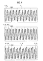
- the identification table T contains for identifying the in Fig. 4 illustrated Normrippelmuster the in Tab.2 contained information: Tab. 2 engine type coding Condition for ripple detection Specifications A 1: 0: 0: 0 "1": A R > S 2 ........ "0": S 1 ⁇ A R ⁇ S 2 B -1: 0: 0: 0 "-1”: A R ⁇ S 1 ........ "0”: S 1 ⁇ A R ⁇ S 2 C 1: -1: 00 "1”: A R > S 2 ........ "-1”: A R ⁇ S 1 "0”: S 1 ⁇ A R ⁇ S 2 ........ ......... ........ .
- the threshold values are here, for example by empirical experiments, under the condition S 1 ⁇ S 2 suitable to determine.
- S 1 and S 2 are selected such that their respective values are 90% and 110%, respectively, of the average ripple amplitude A R of a non-excellent current ripple R N.
- the engine detection module 14 checks on the basis of the received Rippelamplituden A R for each stored engine type the conditions for the identification of the individual current ripple R of the associated ripple pattern in a condition chain. As soon as the engine detection module 14 identifies the ripple pattern of the engine 2 with one of the stored ripple patterns, the engine detection module 14 aborts the detection routine and transmits those characteristic data belonging to the ripple pattern in the characteristic table T as new operation data D B into the engine Operating data memory 16, whereupon the adjusting device 1 goes into normal operation.
- the motor detection module 14 concretely checks in a first step whether the standard ripple pattern of the motor 2 corresponds to the first-stored standard ripple pattern 1: 0: 0: 0 of the motor type "A". It accordingly checks whether one of the received ripple amplitudes A R exceeds the threshold value S 2 .
- the engine detection module 14 checks to avoid errors several, especially three half cycles, in total so the ripple amplitudes A R of twelve detected current ripple R. If no index ripple of the type "1" is detected, the engine detection module 14 goes to the test of the engine type "B" corresponding standard ripple pattern -1: 0: 0: 0 over.
- the motor recognition module 14 checks to determine the current ripple R N of the type "0" whether the three subsequently received ripple amplitudes A R satisfy the condition S 1 ⁇ A R ⁇ S 2 . If this is the case, the engine detection module 14 aborts the detection routine, assigns the engine 2 to the engine type "B" and transmits the associated characteristics from the characteristic data table T into the operation data memory 16 as new operation data D B.
- the actuating device 1 is operated with the standard characteristic data D S.
Landscapes
- Engineering & Computer Science (AREA)
- Power Engineering (AREA)
- Control Of Direct Current Motors (AREA)
- Control Of Electric Motors In General (AREA)
- Tests Of Circuit Breakers, Generators, And Electric Motors (AREA)
Claims (8)
- Procédé de détection automatique d'un moteur à courant continu (2) commuté mécaniquement,• d'après lequel on relève une grandeur de moteur (Ew) électrique,• d'après lequel on détermine des ondulations de courant (R) au cours de la loi de variation de cette grandeur de moteur (EW),• d'après lequel l'amplitude (AR), la durée et/ou la localisation temporelle des ondulations de courant (R) ayant été détectées, sont traitées et comparées à des modèles d'ondulations connus au préalable, et• d'après lequel on sélectionne dans un tableau de données caractéristiques (T) connu au préalable, un certain nombre de données caractéristiques associées à un type de moteur déterminé, lorsque l'amplitude (AR), la durée et/ou la localisation temporelle des ondulations de courant (R) ayant été détectées concordent avec un modèle d'ondulations, qui est associé à ce type de moteur.
- Procédé selon la revendication 1,
d'après lequel en guise de grandeur de moteur, on utilise la force contre-électromotrice (E) ou une grandeur (Ew) dérivée de celle-ci. - Procédé selon la revendication 2,
d'après lequel la force contre-électromotrice (E) est calculée, au regard du courant de moteur (Ia) mesuré et de la tension de moteur (Um) mesurée, au moyen d'un modèle de moteur (10). - Procédé selon la revendication 2 ou la revendication 3,
d'après lequel on utilise en guise de grandeur de moteur pour la détermination des ondulations de courant (R), une fraction alternative (Ew) de la force contre-électromotrice (E). - Procédé selon l'une des revendications 1 à 4, d'après lequel la concordance des ondulations de courant (R) ayant été détectées, avec un modèle d'ondulations, est testée à l'aide d'une comparaison de l'amplitude (AR), de la durée et/ou de la localisation temporelle des ondulations de courant (R) ayant été détectées, avec des valeurs de seuil stockées dans le tableau de données caractéristiques (T) pour ce modèle d'ondulations.
- Unité de commande (5) pour la commande d'un moteur à courant continu (2) commuté mécaniquement d'un dispositif de réglage (1) pour un véhicule automobile, cette unité de commande (5) étant conçue pour exécuter le procédé selon l'une des revendications 1 à 5.
- Dispositif de réglage (1) pour un véhicule automobile, comprenant un moteur à courant continu (2) commuté mécaniquement et une unité de commande (5) selon la revendication 6.
- Utilisation d'un moteur à courant continu (2) commuté mécaniquement, qui est codé par modification mécanique et/ou électromécanique, de façon à présenter un modèle d'ondulations de courant (29) caractéristique, pour l'identification d'un type de moteur déterminé, auquel appartient le moteur à courant continu (2), par le relevé et le traitement des ondulations de courant (R) engendrées par le moteur à courant continu (2), notamment à l'aide du procédé selon l'une des revendications 1 à 5.
Applications Claiming Priority (2)
| Application Number | Priority Date | Filing Date | Title |
|---|---|---|---|
| DE102009013063 | 2009-03-16 | ||
| PCT/EP2010/001634 WO2010105794A2 (fr) | 2009-03-16 | 2010-03-16 | Détection automatique d'un moteur à courant continu commuté mécaniquement |
Publications (2)
| Publication Number | Publication Date |
|---|---|
| EP2409397A2 EP2409397A2 (fr) | 2012-01-25 |
| EP2409397B1 true EP2409397B1 (fr) | 2013-05-15 |
Family
ID=42740044
Family Applications (1)
| Application Number | Title | Priority Date | Filing Date |
|---|---|---|---|
| EP10713817.4A Not-in-force EP2409397B1 (fr) | 2009-03-16 | 2010-03-16 | Détection automatique d'un moteur à courant continu commuté mécaniquement |
Country Status (5)
| Country | Link |
|---|---|
| US (1) | US8354808B2 (fr) |
| EP (1) | EP2409397B1 (fr) |
| CN (1) | CN102356541B (fr) |
| BR (1) | BRPI1009495A2 (fr) |
| WO (1) | WO2010105794A2 (fr) |
Cited By (1)
| Publication number | Priority date | Publication date | Assignee | Title |
|---|---|---|---|---|
| DE102014202247A1 (de) * | 2014-02-07 | 2015-08-13 | Continental Automotive Gmbh | Korrektur der Ankerposition einer Gleichstrommaschine |
Families Citing this family (7)
| Publication number | Priority date | Publication date | Assignee | Title |
|---|---|---|---|---|
| EP2409396B1 (fr) * | 2009-03-16 | 2013-06-05 | Brose Fahrzeugteile GmbH & Co. Kommanditgesellschaft, Hallstadt | Correction des erreurs de comptage dans l'analyse des ondulations de courant sur un moteur à courant continu |
| DE102010009662A1 (de) * | 2010-02-27 | 2011-09-01 | Volkswagen Ag | Verfahren zur Parametrierung eines Steuergeräts für ein Fahrzeug sowie entsprechendes Steuergerät und Fahrzeug |
| NL2019723B1 (en) | 2017-10-13 | 2019-04-23 | Mci Mirror Controls Int Netherlands B V | Method and device for providing information on an annular displacement of a DC electromotor |
| CN108270376A (zh) * | 2018-01-22 | 2018-07-10 | 青岛海尔空调电子有限公司 | 配置空调变频器参数的方法及装置 |
| CN112203805B (zh) * | 2018-04-17 | 2023-07-25 | Abb瑞士股份有限公司 | 用于机器人控制的方法和装置 |
| US11844432B2 (en) | 2020-03-27 | 2023-12-19 | La-Z-Boy Incorporated | Furniture motion control system |
| US12456939B2 (en) | 2023-09-29 | 2025-10-28 | GE Precision Healthcare LLC | Device and method for automatic detection and configuration of a motor |
Family Cites Families (11)
| Publication number | Priority date | Publication date | Assignee | Title |
|---|---|---|---|---|
| DE4135873C2 (de) * | 1991-10-26 | 2003-01-30 | Brose Fahrzeugteile | Verfahren und Vorrichtung zur Erfassung der Position und Drehrichtung und/oder zur Erfassung dynamischer Kenngrößen von fremdkraftbetätigten Verstellungen eines Verstellobjektes |
| US6054787A (en) * | 1999-04-12 | 2000-04-25 | Ngai Keung Metal & Plastic Manufactory Ltd | Electric motor |
| JP2002335699A (ja) * | 2001-05-09 | 2002-11-22 | Hitachi Ltd | 交流モータの制御装置 |
| US7098624B2 (en) * | 2002-07-12 | 2006-08-29 | Toyota Jidosha Kabushiki Kaisha | Method and system for detecting the disconnection of an auxiliary power supply from a poly-phase motor |
| SE526852C2 (sv) * | 2003-06-26 | 2005-11-08 | Kongsberg Automotive Ab | Metod och arrangemang för styrning av likströmsmotor |
| JP4763509B2 (ja) * | 2006-05-23 | 2011-08-31 | アイシン精機株式会社 | リプル検出装置 |
| DE102006049123B4 (de) * | 2006-10-18 | 2013-01-24 | Continental Automotive Gmbh | Verfahren zur Ermittlung der Drehstellung des Rotors eines mechanisch kommutierten Gleichstrom-Stellmotors |
| US20080298784A1 (en) * | 2007-06-04 | 2008-12-04 | Mark Allen Kastner | Method of Sensing Speed of Electric Motors and Generators |
| CN101087125B (zh) * | 2007-06-25 | 2011-05-11 | 中国科学院电工研究所 | 一种具有寿命预测功能的电动汽车电机驱动系统 |
| DE102007034613A1 (de) * | 2007-07-25 | 2009-01-29 | Robert Bosch Gmbh | Elektrische Maschine mit einem Kommutator, sowie Verfahren zum Betreiben der elektrischen Maschine |
| DE102009014264A1 (de) * | 2008-09-12 | 2010-04-15 | Brose Fahrzeugteile Gmbh & Co. Kommanditgesellschaft, Hallstadt | Verfahren und Vorrichtung zur Verarbeitung eines Stromrippel aufweisenden Motorsignals eines Gleichstrommotors |
-
2010
- 2010-03-16 BR BRPI1009495A patent/BRPI1009495A2/pt not_active IP Right Cessation
- 2010-03-16 CN CN201080012263.4A patent/CN102356541B/zh not_active Expired - Fee Related
- 2010-03-16 EP EP10713817.4A patent/EP2409397B1/fr not_active Not-in-force
- 2010-03-16 WO PCT/EP2010/001634 patent/WO2010105794A2/fr not_active Ceased
-
2011
- 2011-09-16 US US13/235,331 patent/US8354808B2/en not_active Expired - Fee Related
Cited By (1)
| Publication number | Priority date | Publication date | Assignee | Title |
|---|---|---|---|---|
| DE102014202247A1 (de) * | 2014-02-07 | 2015-08-13 | Continental Automotive Gmbh | Korrektur der Ankerposition einer Gleichstrommaschine |
Also Published As
| Publication number | Publication date |
|---|---|
| US8354808B2 (en) | 2013-01-15 |
| WO2010105794A2 (fr) | 2010-09-23 |
| WO2010105794A3 (fr) | 2011-03-03 |
| BRPI1009495A2 (pt) | 2016-03-15 |
| US20120062156A1 (en) | 2012-03-15 |
| CN102356541A (zh) | 2012-02-15 |
| CN102356541B (zh) | 2015-08-05 |
| EP2409397A2 (fr) | 2012-01-25 |
Similar Documents
| Publication | Publication Date | Title |
|---|---|---|
| EP2409397B1 (fr) | Détection automatique d'un moteur à courant continu commuté mécaniquement | |
| EP2409396B1 (fr) | Correction des erreurs de comptage dans l'analyse des ondulations de courant sur un moteur à courant continu | |
| DE19729238C1 (de) | Verfahren zum Ermitteln der Drehzahl bei mechanisch kommutierten Gleichstrommotoren | |
| EP2561608B1 (fr) | Traitement d'une grandeur d'un moteur à courant continu | |
| EP0899847B1 (fr) | Procédé pour la détermination de la position et de la direction du mouvement d'une partie mobile entraînée par un moteur électrique | |
| DE102009034664A1 (de) | Verfahren und Vorrichtung zur Ermittlung der Stellposition eines Verstellelements eines Kraftfahrzeugs | |
| DE102012108912A1 (de) | Diagnose von Überstrombedingungen in Steuerungen bipolarer Motoren | |
| DE102010009821A1 (de) | Verfahren zur Bestimmung der Stellposition eines Verstellteils | |
| EP1514342B1 (fr) | Procede et ensemble de circuits pour faire fonctionner des moteurs pas a pas | |
| DE102013218041A1 (de) | Verfahren zum Betreiben eines Elektromotors | |
| EP3152830B1 (fr) | Procédé d'actionnement d'un moteur à collecteur à balais d'un entraînement de réglage et entraînement de réglage | |
| EP1381148A2 (fr) | Capteur d'angle de rotation à haute résolution pour moteur DC | |
| DE4211495C2 (de) | Vorrichtung zur Drehmomentabschaltung eines Kondensatormotors | |
| EP2474090B1 (fr) | Procédé et dispositif pour déterminer une position de rotor d'une machine synchrone | |
| EP3413459B1 (fr) | Procédé de détection de blocage des moteurs électriques à commutation électrique | |
| EP0890217A1 (fr) | Detection de venue en butee et de blocage d'un moteur pas a pas | |
| DE102006049123B4 (de) | Verfahren zur Ermittlung der Drehstellung des Rotors eines mechanisch kommutierten Gleichstrom-Stellmotors | |
| DE102009019183B4 (de) | Interpolationsverfahren zur Überbrückung der Freilaufphase eines Stellvorgangs | |
| EP2181456B1 (fr) | Procédé pour détecter un état de commutation | |
| EP2180591B1 (fr) | Procédé destiné à la détermination automatique de la dynamique systémique et/ou de la position d'un moteur à courant continu excité en permanence | |
| DE102018124247A1 (de) | Verfahren und vorrichtung zur blockadeerkennung bei einem elektromotor | |
| WO2010118978A2 (fr) | Procédé pour utiliser un circuit de commande, en particulier pour une application sur un véhicule automobile | |
| DE19861352B4 (de) | Verfahren zur Steuerung und Regelung motorisch angetriebener Verstelleinrichtungen in Kraftfahrzeugen | |
| EP2319169A1 (fr) | Procédé de détermination de la position du rotor d'une machine électrique et dispositif destiné à cette fin | |
| DE102020131811A1 (de) | Verfahren zur Steuerung eines Stellantriebs |
Legal Events
| Date | Code | Title | Description |
|---|---|---|---|
| PUAI | Public reference made under article 153(3) epc to a published international application that has entered the european phase |
Free format text: ORIGINAL CODE: 0009012 |
|
| 17P | Request for examination filed |
Effective date: 20111017 |
|
| AK | Designated contracting states |
Kind code of ref document: A2 Designated state(s): AT BE BG CH CY CZ DE DK EE ES FI FR GB GR HR HU IE IS IT LI LT LU LV MC MK MT NL NO PL PT RO SE SI SK SM TR |
|
| DAX | Request for extension of the european patent (deleted) | ||
| GRAP | Despatch of communication of intention to grant a patent |
Free format text: ORIGINAL CODE: EPIDOSNIGR1 |
|
| GRAS | Grant fee paid |
Free format text: ORIGINAL CODE: EPIDOSNIGR3 |
|
| GRAA | (expected) grant |
Free format text: ORIGINAL CODE: 0009210 |
|
| AK | Designated contracting states |
Kind code of ref document: B1 Designated state(s): AT BE BG CH CY CZ DE DK EE ES FI FR GB GR HR HU IE IS IT LI LT LU LV MC MK MT NL NO PL PT RO SE SI SK SM TR |
|
| REG | Reference to a national code |
Ref country code: GB Ref legal event code: FG4D Free format text: NOT ENGLISH Ref country code: CH Ref legal event code: EP |
|
| REG | Reference to a national code |
Ref country code: AT Ref legal event code: REF Ref document number: 612555 Country of ref document: AT Kind code of ref document: T Effective date: 20130615 |
|
| REG | Reference to a national code |
Ref country code: IE Ref legal event code: FG4D Free format text: LANGUAGE OF EP DOCUMENT: GERMAN |
|
| REG | Reference to a national code |
Ref country code: DE Ref legal event code: R096 Ref document number: 502010003363 Country of ref document: DE Effective date: 20130711 |
|
| REG | Reference to a national code |
Ref country code: LT Ref legal event code: MG4D |
|
| REG | Reference to a national code |
Ref country code: NL Ref legal event code: VDEP Effective date: 20130515 |
|
| PG25 | Lapsed in a contracting state [announced via postgrant information from national office to epo] |
Ref country code: ES Free format text: LAPSE BECAUSE OF FAILURE TO SUBMIT A TRANSLATION OF THE DESCRIPTION OR TO PAY THE FEE WITHIN THE PRESCRIBED TIME-LIMIT Effective date: 20130826 Ref country code: PT Free format text: LAPSE BECAUSE OF FAILURE TO SUBMIT A TRANSLATION OF THE DESCRIPTION OR TO PAY THE FEE WITHIN THE PRESCRIBED TIME-LIMIT Effective date: 20130916 Ref country code: NO Free format text: LAPSE BECAUSE OF FAILURE TO SUBMIT A TRANSLATION OF THE DESCRIPTION OR TO PAY THE FEE WITHIN THE PRESCRIBED TIME-LIMIT Effective date: 20130815 Ref country code: IS Free format text: LAPSE BECAUSE OF FAILURE TO SUBMIT A TRANSLATION OF THE DESCRIPTION OR TO PAY THE FEE WITHIN THE PRESCRIBED TIME-LIMIT Effective date: 20130915 Ref country code: GR Free format text: LAPSE BECAUSE OF FAILURE TO SUBMIT A TRANSLATION OF THE DESCRIPTION OR TO PAY THE FEE WITHIN THE PRESCRIBED TIME-LIMIT Effective date: 20130816 Ref country code: SI Free format text: LAPSE BECAUSE OF FAILURE TO SUBMIT A TRANSLATION OF THE DESCRIPTION OR TO PAY THE FEE WITHIN THE PRESCRIBED TIME-LIMIT Effective date: 20130515 Ref country code: FI Free format text: LAPSE BECAUSE OF FAILURE TO SUBMIT A TRANSLATION OF THE DESCRIPTION OR TO PAY THE FEE WITHIN THE PRESCRIBED TIME-LIMIT Effective date: 20130515 Ref country code: SE Free format text: LAPSE BECAUSE OF FAILURE TO SUBMIT A TRANSLATION OF THE DESCRIPTION OR TO PAY THE FEE WITHIN THE PRESCRIBED TIME-LIMIT Effective date: 20130515 Ref country code: LT Free format text: LAPSE BECAUSE OF FAILURE TO SUBMIT A TRANSLATION OF THE DESCRIPTION OR TO PAY THE FEE WITHIN THE PRESCRIBED TIME-LIMIT Effective date: 20130515 |
|
| PG25 | Lapsed in a contracting state [announced via postgrant information from national office to epo] |
Ref country code: PL Free format text: LAPSE BECAUSE OF FAILURE TO SUBMIT A TRANSLATION OF THE DESCRIPTION OR TO PAY THE FEE WITHIN THE PRESCRIBED TIME-LIMIT Effective date: 20130515 Ref country code: HR Free format text: LAPSE BECAUSE OF FAILURE TO SUBMIT A TRANSLATION OF THE DESCRIPTION OR TO PAY THE FEE WITHIN THE PRESCRIBED TIME-LIMIT Effective date: 20130515 Ref country code: BG Free format text: LAPSE BECAUSE OF FAILURE TO SUBMIT A TRANSLATION OF THE DESCRIPTION OR TO PAY THE FEE WITHIN THE PRESCRIBED TIME-LIMIT Effective date: 20130815 |
|
| PG25 | Lapsed in a contracting state [announced via postgrant information from national office to epo] |
Ref country code: LV Free format text: LAPSE BECAUSE OF FAILURE TO SUBMIT A TRANSLATION OF THE DESCRIPTION OR TO PAY THE FEE WITHIN THE PRESCRIBED TIME-LIMIT Effective date: 20130515 |
|
| PG25 | Lapsed in a contracting state [announced via postgrant information from national office to epo] |
Ref country code: EE Free format text: LAPSE BECAUSE OF FAILURE TO SUBMIT A TRANSLATION OF THE DESCRIPTION OR TO PAY THE FEE WITHIN THE PRESCRIBED TIME-LIMIT Effective date: 20130515 Ref country code: CZ Free format text: LAPSE BECAUSE OF FAILURE TO SUBMIT A TRANSLATION OF THE DESCRIPTION OR TO PAY THE FEE WITHIN THE PRESCRIBED TIME-LIMIT Effective date: 20130515 Ref country code: SK Free format text: LAPSE BECAUSE OF FAILURE TO SUBMIT A TRANSLATION OF THE DESCRIPTION OR TO PAY THE FEE WITHIN THE PRESCRIBED TIME-LIMIT Effective date: 20130515 Ref country code: DK Free format text: LAPSE BECAUSE OF FAILURE TO SUBMIT A TRANSLATION OF THE DESCRIPTION OR TO PAY THE FEE WITHIN THE PRESCRIBED TIME-LIMIT Effective date: 20130515 |
|
| PG25 | Lapsed in a contracting state [announced via postgrant information from national office to epo] |
Ref country code: RO Free format text: LAPSE BECAUSE OF FAILURE TO SUBMIT A TRANSLATION OF THE DESCRIPTION OR TO PAY THE FEE WITHIN THE PRESCRIBED TIME-LIMIT Effective date: 20130515 Ref country code: NL Free format text: LAPSE BECAUSE OF FAILURE TO SUBMIT A TRANSLATION OF THE DESCRIPTION OR TO PAY THE FEE WITHIN THE PRESCRIBED TIME-LIMIT Effective date: 20130515 Ref country code: IT Free format text: LAPSE BECAUSE OF FAILURE TO SUBMIT A TRANSLATION OF THE DESCRIPTION OR TO PAY THE FEE WITHIN THE PRESCRIBED TIME-LIMIT Effective date: 20130515 |
|
| PLBE | No opposition filed within time limit |
Free format text: ORIGINAL CODE: 0009261 |
|
| STAA | Information on the status of an ep patent application or granted ep patent |
Free format text: STATUS: NO OPPOSITION FILED WITHIN TIME LIMIT |
|
| 26N | No opposition filed |
Effective date: 20140218 |
|
| REG | Reference to a national code |
Ref country code: DE Ref legal event code: R097 Ref document number: 502010003363 Country of ref document: DE Effective date: 20140218 |
|
| PG25 | Lapsed in a contracting state [announced via postgrant information from national office to epo] |
Ref country code: LU Free format text: LAPSE BECAUSE OF FAILURE TO SUBMIT A TRANSLATION OF THE DESCRIPTION OR TO PAY THE FEE WITHIN THE PRESCRIBED TIME-LIMIT Effective date: 20140316 |
|
| REG | Reference to a national code |
Ref country code: CH Ref legal event code: PL |
|
| GBPC | Gb: european patent ceased through non-payment of renewal fee |
Effective date: 20140316 |
|
| REG | Reference to a national code |
Ref country code: IE Ref legal event code: MM4A |
|
| PG25 | Lapsed in a contracting state [announced via postgrant information from national office to epo] |
Ref country code: GB Free format text: LAPSE BECAUSE OF NON-PAYMENT OF DUE FEES Effective date: 20140316 Ref country code: LI Free format text: LAPSE BECAUSE OF NON-PAYMENT OF DUE FEES Effective date: 20140331 Ref country code: CH Free format text: LAPSE BECAUSE OF NON-PAYMENT OF DUE FEES Effective date: 20140331 Ref country code: IE Free format text: LAPSE BECAUSE OF NON-PAYMENT OF DUE FEES Effective date: 20140316 |
|
| REG | Reference to a national code |
Ref country code: FR Ref legal event code: PLFP Year of fee payment: 6 |
|
| PGFP | Annual fee paid to national office [announced via postgrant information from national office to epo] |
Ref country code: FR Payment date: 20150309 Year of fee payment: 6 |
|
| PG25 | Lapsed in a contracting state [announced via postgrant information from national office to epo] |
Ref country code: MT Free format text: LAPSE BECAUSE OF FAILURE TO SUBMIT A TRANSLATION OF THE DESCRIPTION OR TO PAY THE FEE WITHIN THE PRESCRIBED TIME-LIMIT Effective date: 20130515 |
|
| PG25 | Lapsed in a contracting state [announced via postgrant information from national office to epo] |
Ref country code: SM Free format text: LAPSE BECAUSE OF FAILURE TO SUBMIT A TRANSLATION OF THE DESCRIPTION OR TO PAY THE FEE WITHIN THE PRESCRIBED TIME-LIMIT Effective date: 20130515 |
|
| REG | Reference to a national code |
Ref country code: AT Ref legal event code: MM01 Ref document number: 612555 Country of ref document: AT Kind code of ref document: T Effective date: 20150316 |
|
| PG25 | Lapsed in a contracting state [announced via postgrant information from national office to epo] |
Ref country code: MC Free format text: LAPSE BECAUSE OF FAILURE TO SUBMIT A TRANSLATION OF THE DESCRIPTION OR TO PAY THE FEE WITHIN THE PRESCRIBED TIME-LIMIT Effective date: 20130515 |
|
| PG25 | Lapsed in a contracting state [announced via postgrant information from national office to epo] |
Ref country code: CY Free format text: LAPSE BECAUSE OF FAILURE TO SUBMIT A TRANSLATION OF THE DESCRIPTION OR TO PAY THE FEE WITHIN THE PRESCRIBED TIME-LIMIT Effective date: 20130515 |
|
| PG25 | Lapsed in a contracting state [announced via postgrant information from national office to epo] |
Ref country code: HU Free format text: LAPSE BECAUSE OF FAILURE TO SUBMIT A TRANSLATION OF THE DESCRIPTION OR TO PAY THE FEE WITHIN THE PRESCRIBED TIME-LIMIT; INVALID AB INITIO Effective date: 20100316 Ref country code: TR Free format text: LAPSE BECAUSE OF FAILURE TO SUBMIT A TRANSLATION OF THE DESCRIPTION OR TO PAY THE FEE WITHIN THE PRESCRIBED TIME-LIMIT Effective date: 20130515 |
|
| REG | Reference to a national code |
Ref country code: DE Ref legal event code: R081 Ref document number: 502010003363 Country of ref document: DE Owner name: BROSE FAHRZEUGTEILE GMBH & CO. KOMMANDITGESELL, DE Free format text: FORMER OWNER: BROSE FAHRZEUGTEILE GMBH & CO. KOMMANDITGESELLSCHAFT, HALLSTADT, 96103 HALLSTADT, DE |
|
| PG25 | Lapsed in a contracting state [announced via postgrant information from national office to epo] |
Ref country code: AT Free format text: LAPSE BECAUSE OF NON-PAYMENT OF DUE FEES Effective date: 20150316 |
|
| REG | Reference to a national code |
Ref country code: FR Ref legal event code: ST Effective date: 20161130 |
|
| PG25 | Lapsed in a contracting state [announced via postgrant information from national office to epo] |
Ref country code: FR Free format text: LAPSE BECAUSE OF NON-PAYMENT OF DUE FEES Effective date: 20160331 |
|
| PG25 | Lapsed in a contracting state [announced via postgrant information from national office to epo] |
Ref country code: BE Free format text: LAPSE BECAUSE OF NON-PAYMENT OF DUE FEES Effective date: 20140331 |
|
| PG25 | Lapsed in a contracting state [announced via postgrant information from national office to epo] |
Ref country code: MK Free format text: LAPSE BECAUSE OF FAILURE TO SUBMIT A TRANSLATION OF THE DESCRIPTION OR TO PAY THE FEE WITHIN THE PRESCRIBED TIME-LIMIT Effective date: 20130515 |
|
| PGFP | Annual fee paid to national office [announced via postgrant information from national office to epo] |
Ref country code: DE Payment date: 20190331 Year of fee payment: 10 |
|
| REG | Reference to a national code |
Ref country code: DE Ref legal event code: R119 Ref document number: 502010003363 Country of ref document: DE |
|
| PG25 | Lapsed in a contracting state [announced via postgrant information from national office to epo] |
Ref country code: DE Free format text: LAPSE BECAUSE OF NON-PAYMENT OF DUE FEES Effective date: 20201001 |