EP2409397B1 - Automatische erkennung eines mechanisch kommutierten gleichstrommotors - Google Patents
Automatische erkennung eines mechanisch kommutierten gleichstrommotors Download PDFInfo
- Publication number
- EP2409397B1 EP2409397B1 EP10713817.4A EP10713817A EP2409397B1 EP 2409397 B1 EP2409397 B1 EP 2409397B1 EP 10713817 A EP10713817 A EP 10713817A EP 2409397 B1 EP2409397 B1 EP 2409397B1
- Authority
- EP
- European Patent Office
- Prior art keywords
- motor
- current
- ripple
- engine
- control unit
- Prior art date
- Legal status (The legal status is an assumption and is not a legal conclusion. Google has not performed a legal analysis and makes no representation as to the accuracy of the status listed.)
- Not-in-force
Links
- 238000001514 detection method Methods 0.000 title claims description 32
- 238000000034 method Methods 0.000 claims description 21
- 238000012986 modification Methods 0.000 claims description 4
- 230000004048 modification Effects 0.000 claims description 4
- 230000003213 activating effect Effects 0.000 claims 1
- 238000011156 evaluation Methods 0.000 description 6
- 238000010586 diagram Methods 0.000 description 3
- 239000002655 kraft paper Substances 0.000 description 3
- 241001295925 Gegenes Species 0.000 description 2
- XEEYBQQBJWHFJM-UHFFFAOYSA-N Iron Chemical group [Fe] XEEYBQQBJWHFJM-UHFFFAOYSA-N 0.000 description 2
- 206010000210 abortion Diseases 0.000 description 2
- 230000008859 change Effects 0.000 description 2
- 230000006870 function Effects 0.000 description 2
- 230000007246 mechanism Effects 0.000 description 2
- 238000012544 monitoring process Methods 0.000 description 2
- 230000004044 response Effects 0.000 description 2
- 230000036962 time dependent Effects 0.000 description 2
- 238000012549 training Methods 0.000 description 2
- 238000004804 winding Methods 0.000 description 2
- 238000012935 Averaging Methods 0.000 description 1
- 238000004458 analytical method Methods 0.000 description 1
- 230000006399 behavior Effects 0.000 description 1
- 230000003247 decreasing effect Effects 0.000 description 1
- 238000002474 experimental method Methods 0.000 description 1
- 230000006698 induction Effects 0.000 description 1
- 238000005259 measurement Methods 0.000 description 1
- 230000010355 oscillation Effects 0.000 description 1
- 230000000737 periodic effect Effects 0.000 description 1
- 230000008569 process Effects 0.000 description 1
- 230000002829 reductive effect Effects 0.000 description 1
- 230000002441 reversible effect Effects 0.000 description 1
- 230000003068 static effect Effects 0.000 description 1
- 230000001360 synchronised effect Effects 0.000 description 1
- 230000002123 temporal effect Effects 0.000 description 1
- 238000012360 testing method Methods 0.000 description 1
Images


Classifications
-
- H—ELECTRICITY
- H02—GENERATION; CONVERSION OR DISTRIBUTION OF ELECTRIC POWER
- H02P—CONTROL OR REGULATION OF ELECTRIC MOTORS, ELECTRIC GENERATORS OR DYNAMO-ELECTRIC CONVERTERS; CONTROLLING TRANSFORMERS, REACTORS OR CHOKE COILS
- H02P7/00—Arrangements for regulating or controlling the speed or torque of electric DC motors
- H02P7/0094—Arrangements for regulating or controlling the speed or torque of electric DC motors wherein the position is detected using the ripple of the current caused by the commutator
-
- H—ELECTRICITY
- H02—GENERATION; CONVERSION OR DISTRIBUTION OF ELECTRIC POWER
- H02K—DYNAMO-ELECTRIC MACHINES
- H02K23/00—DC commutator motors or generators having mechanical commutator; Universal AC/DC commutator motors
- H02K23/66—Structural association with auxiliary electric devices influencing the characteristic of, or controlling, the machine, e.g. with impedances or switches
-
- H—ELECTRICITY
- H02—GENERATION; CONVERSION OR DISTRIBUTION OF ELECTRIC POWER
- H02P—CONTROL OR REGULATION OF ELECTRIC MOTORS, ELECTRIC GENERATORS OR DYNAMO-ELECTRIC CONVERTERS; CONTROLLING TRANSFORMERS, REACTORS OR CHOKE COILS
- H02P7/00—Arrangements for regulating or controlling the speed or torque of electric DC motors
- H02P7/03—Arrangements for regulating or controlling the speed or torque of electric DC motors for controlling the direction of rotation of DC motors
- H02P7/04—Arrangements for regulating or controlling the speed or torque of electric DC motors for controlling the direction of rotation of DC motors by means of a H-bridge circuit
Definitions
- the invention relates to a method for the automatic detection of a mechanically commutated direct current motor (commutator motor).
- the invention further relates to an apparatus for carrying out the method and to the use of a modified commutator motor for the method.
- Commutator motors are used in particular as servo motors in the context of adjusting devices (control systems) in a motor vehicle, e.g. as a drive of an electric window or an electric seat adjustment.
- adjusting devices control systems
- the knowledge of specific engine characteristics such as e.g. the number of poles, the fin pitch, the motor resistance, the motor inductance, the rated current, the rated voltage, etc. required.
- One or more of these characteristics is needed, in particular, to calculate the engine position or engine load, or other operating quantity of the engine, based on an engine model (i.e., a mathematical formula simulating the electrical, thermal, and / or mechanical behavior of the engine).
- the respective required motor characteristics are usually stored in a control unit of the control system software.
- the invention has for its object to enable a flexible and easy replacement of a commutator motor in a motor vehicle control device.
- the object is achieved by a method with the features of claim 1 for automatically detecting the engine with respect to the engine type to which he belongs.
- the invention is generally based on the idea of encoding the commutator motors provided for use in such adjusting devices by mechanical and / or electromechanical modification in such a way that each type of motor can be identified on the basis of the characteristic of the current ripple generated by it.
- a (motor current) ripple is hereby designated a characteristic ripple (i.e., periodic, pulse-like fluctuations) of the motor current, which is caused by the commutation of the DC motor.
- an electric motor size are detected, and current ripple detected in the time course of this engine size. Furthermore, the amplitude, duration and / or temporal position of the detected ripples are evaluated and compared with previously known ripple patterns. In this case, the characteristics assigned to a specific engine type are selected from a previously known characteristic data table if the amplitude, duration and / or time position of the detected ripple (in accordance with predefined criteria) coincide with a ripple pattern assigned to this engine type.
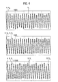
- 1 engine type coding scheme turns ratio A 1: 0: 0: 0 27: 25: 25: 25: 25 B -1: 0: 0: 0 23: 25: 25: 25 C 1: -1: 0: 0 27: 23: 25: 25 D 1: 1: 0: 0 27: 27: 25: 25 e 1: 0: 1: 0 27: 25: 27: 25 ... ... ...
- the coding of the type -1: 0: 0: 0 is alternatively achieved by an eight-ply motor with an advantageous turn ratio of 26: 24: 25: 25: 27: 26: 25: 25.
- the ripple pattern repeats with every engine half-cycle.
- the detected motor size is preferably the counter electromotive force (also referred to as back electromagnetic force, in short: b-EMF or mutual induction voltage), which is generated during operation of the motor.
- the b-EMF is preferably calculated based on the measured motor current and the measured motor voltage from a given motor model.
- the quantities E, Um and l a are time-dependent measured variables, ie functions of time.
- the variables R a and L a are constants that are assigned to the implementation of the method described above with predetermined default values (the actual motor resistance and the actual inductance are as motor-specific characteristics only after the engine detection, and thus only after the execution of the method described above).
- the detected motor size may also be the motor current (more precisely the current strength thereof) or the motor voltage, preferably the self-induction component thereof.
- the control unit is formed in an expedient embodiment substantially by a microprocessor, the measured values of one or more engine sizes, in particular the motor current and the motor voltage are supplied, and in which the method is otherwise implemented by software technology.
- the object is also achieved according to the invention by the features of claim 8, ie by the use of a motor described in the above-described manner for identifying a particular type of motor to which the DC motor belongs, by detecting and evaluating the DC motor generated current ripple, in particular by the method according to the invention or in the adjusting device according to the invention.
- adjusting device 1 is an example of an electric window, as it is usually used in a passenger vehicle.
- the adjusting device 1 comprises a mechanically commutated (DC) motor 2, which acts via a (merely indicated) actuating mechanism 3 on a (motor vehicle) window 4 and reversibly adjusted this between an open position and a closed position.
- DC mechanically commutated
- the adjusting device 1 further comprises a control unit 5, a motor switch 6 and a current sensor 7.
- the power switch 6 is connected in a (two-phase) power supply circuit 8 for the motor 2. It comprises two independently controllable individual switches, by the switching position of both motor connections can be selectively connected to the positive pole or the negative pole (ground) of the power supply line 8. By appropriate position of the individual switch of the engine switch 6, the motor 2 can thus be switched on and off in each of its two directions of rotation and reversed to reverse the direction of rotation.
- the current sensor 7 is a measuring resistor, via which a current-proportional voltage can be tapped as a measuring signal for the motor current I a flowing in the power supply line 8.
- This measuring signal is simplifying hereinafter also referred to as motor current I a , especially since it represents a measure of the strength of the latter.
- the current sensor 7 leads in this sense the motor current I a , more precisely the characteristic of the motor current I a measurement signal of the control unit 5 as an input to.
- the control unit 5 is supplied with the motor voltage Um applied in the power supply line 8.
- the control unit 5 is used to control the motor 2 by appropriate wiring of the motor switch 6. It includes a switching module 9, which actuates the motor switch 6 in response to external control commands C and in response to a motor position signal M.
- the motor position signal M is a - basically arbitrarily definable - manipulated variable from which the position of the window 4 is derivable.
- the engine position signal M can in this case be defined in particular as the rotational angle of the engine 2 (in units of the angular dimension).
- the motor position signal M is generated but as a dimensionless number, which in the manner described in more detail below from the counting of current ripples R (FIG. Fig. 3 and 4 ) of the motor current I a results.
- control unit 5 To determine the motor position signal M, the control unit 5 comprises a so-called motor model 10, a (AC) filter 11, a (ripple) detection module 12 and an evaluation module 13.
- the control unit 5 further comprises an engine detection module 14, a characteristic database 15 and an operating data memory 16.
- the control unit 5 is also supplied via a branch line 17 from the power supply line 8, an electrical supply voltage U v .
- the control unit 5 is formed in a preferred embodiment of the adjusting device 1 by a microcontroller.
- the switching module 9, the motor model 10, the filter 11 and the modules 12 to 14 are in this case in particular in the form of software components, i. implemented functional components of a software implemented in the microcontroller.
- the control unit 5 can also be realized at least partially in the form of an analog and / or digital electrical circuit, wherein the switching module 9, the motor model 10, the filter 11 and the modules 12 to 14 are realized in the form of electrical circuits.
- hybrid forms are conceivable in which a plurality of the components of the control unit 5 are partly implemented by circuitry, and partly by software.
- the above structure of the components of the control unit 5 also has only functional character. In particular, these components can be combined as desired into larger circuit or program units or even more finely subdivided.
- the identification database 15 and the operating data memory 16 are analogous to functionally different memory structures, which - on the hardware side - can optionally be implemented in separate memory modules or a shared memory hardware.
- the motor model 10 is - a program or circuitry - a mathematical formula of the in Glg. 1 implemented by the form already introduced at-counter-electromotive force (b-EMF) E as a function of the motor current I a and the motor voltage Um is calculated.
- the motor current I a and the motor voltage Um are supplied to the motor model 10 as input variables.
- the parameters of the motor model 10, namely the ohmic (motor) resistor R a , and the (motor) inductance L a are the motor model 10 as constants.
- the after Glg. 1 calculated electromotive force E is delivered from the engine model 10 to the nachrieschaltet filter 11.
- the half-cycle duration T Z can hereby be calculated by the control unit 5 from the time change of the motor position signal M and supplied to the filter 11 with the respective current amount.
- the half-cycle duration T Z the filter 11 but fixed as a constant. This constant is chosen in particular in such a way that its value the average half-cycle duration T Z of the motor 2 corresponds to its steady state operation.
- the filter 11 may alternatively be formed as a high pass.
- current ripples R of the motor current I a are expressed in a synchronous oscillation of the b-EMF E, and in particular their alternating component E W.
- the detection module 12 is therefore designed to detect maxima in the time course of the alternating component E W as an indication of the occurrence of a current ripple R.
- the alternating component E W is optionally smoothed before the maximum value search.
- the detection module 12 Upon detection of each maximum in the alternating component E W , the detection module 12 outputs a ripple detection signal S R to the evaluation module 13. In addition, the detection module 12 determines the amount of the alternating component E W at the location of the maximum and transmits this amount as a ripple amplitude A R to the engine detection module 14.
- the ripple detection signals S R thus act as counting pulses for incrementing or decrementing the motor position signal M.
- the evaluation module 13 starts from an initial value M 0 of the motor position signal M, from which the motor position and the window position at the beginning of the setting process can be derived.
- the motor status signal S M has the value +1, as long as the motor 2 is operated in a first direction, and the value -1, as long as the motor 2 is operated in the opposite direction.
- the engine status signal S M has the value 0, on the other hand.
- Fig. 3 By thus broken armature winding a NormrippelGerman 29 is generated in undisturbed, static operation of the motor 2, the in Fig. 3 is represented by the course of the alternating component E w of the b-EMF E against the time t. From the Fig. 3 It can be seen that the standard ripple pattern 29 in each case has a total of four current ripples R per half-cycle Z, ie per 180 ° rotation of the rotor 23.
- Three current ripples R within each half cycle Z have - at least approximately the same ripple amplitude A R - corresponding to the respective maximum value of the alternating component E W.
- These current ripples R are also referred to below as “non-excellent” current ripples R N.
- the fourth current ripple R - "in Fig. 3 visually highlighted by circles - on the other hand in each case has a ripple amplitude A R significantly reduced compared to the other current ripples R. Diester (smaller) current ripple R is thus distinguished from the current ripple R N and is hereinafter referred to as Indexrippel R 1 .
- the standard ripple pattern 29 thus corresponds to the coding described above -1: 0: 0: 0. How out Fig. 3 recognizable, the standard ripple pattern 29 is repeated in undisturbed stationary operation of the motor 2 with each half cycle Z.
- the motor resistance R a , the motor inductance L a , and the typical half-cycle time T Z of the motor 2 are stored in the operating data memory 16 and are provided therefrom to the motor model 10 and the filter 11, respectively.
- the operating data memory 16 are also more characteristics (ie concrete values for other characteristics) of the motor 2, in particular the number of grooves 26 and teeth 27, the number of poles, the fin pitch, the rated voltage, the rated current, etc. deposited.
- operating data D B - The respectively required characteristics of the motor 2 used in the context of the actuator 1 - referred to as operating data D B - are in normal operation of the actuator 1 whose components, in particular the motor model 10 and the filter 11 and (not explicitly shown) the evaluation module 13 and the switching module 9 from the operating data memory 16 provided.
- the operating data D B are stored in the operating data memory 16 but only non-resistive (volatile). They are thus deleted when the control unit 5 is disconnected from the branch line 17, and thus from the supply voltage U v . Likewise, the operating memory 16 does not contain any operating data D B even before the first start-up of the adjusting device 1.
- the standard characteristic data D S are resistive (non-volatile), so that they also outlast a failure of the supply voltage U v .
- the standard characteristic data D S contain standard values for the motor resistance R a , the motor inductance L a and the typical half-cycle duration T Z, as well as the remaining characteristic variables which are best suited for the entirety of the motor types which can be used in principle within the scope of the adjusting device 1.
- the standard characteristic data D S contain average values or - in particular in the case of overload-critical parameters such as the rated voltage and the rated current - generally acceptable minimum values for the characteristic quantities.
- the standard characteristic data D S more or less deviate from the specific device constants of the motor 2 actually used in the context of the adjusting device 1.
- the engine detection module 14 therefore carries out the first startup of the engine 1 after the initial or - after a failure of the supply voltage Uv - re-commissioning of the adjusting device 1, a method for engine detection described in more detail below.
- the engine detection module 14 uses a characteristic data table T stored in the characteristic database 15-likewise resistive-which for each of a plurality of different engine types has a set of specific characteristics, in particular specific values for the engine resistance R a , the engine inductance L a , and the typical Half cycle duration T Z , contains.
- the characteristic database 15 contains information on an assigned standard ripple pattern.
- the Normrippelmuster all stored in the Kennariesbank 15 engine types are always different from each other.
- Each type of motor is thereby coded by its associated Normrippelmuster and uniquely identifiable.
- each associated ripple pattern contains the Kenndat table T as identification information threshold conditions that have to meet the current ripple R N , R 1 of each ripple pattern.
- the identification table T contains for identifying the in Fig. 4 illustrated Normrippelmuster the in Tab.2 contained information: Tab. 2 engine type coding Condition for ripple detection Specifications A 1: 0: 0: 0 "1": A R > S 2 ........ "0": S 1 ⁇ A R ⁇ S 2 B -1: 0: 0: 0 "-1”: A R ⁇ S 1 ........ "0”: S 1 ⁇ A R ⁇ S 2 C 1: -1: 00 "1”: A R > S 2 ........ "-1”: A R ⁇ S 1 "0”: S 1 ⁇ A R ⁇ S 2 ........ ......... ........ .
- the threshold values are here, for example by empirical experiments, under the condition S 1 ⁇ S 2 suitable to determine.
- S 1 and S 2 are selected such that their respective values are 90% and 110%, respectively, of the average ripple amplitude A R of a non-excellent current ripple R N.
- the engine detection module 14 checks on the basis of the received Rippelamplituden A R for each stored engine type the conditions for the identification of the individual current ripple R of the associated ripple pattern in a condition chain. As soon as the engine detection module 14 identifies the ripple pattern of the engine 2 with one of the stored ripple patterns, the engine detection module 14 aborts the detection routine and transmits those characteristic data belonging to the ripple pattern in the characteristic table T as new operation data D B into the engine Operating data memory 16, whereupon the adjusting device 1 goes into normal operation.
- the motor detection module 14 concretely checks in a first step whether the standard ripple pattern of the motor 2 corresponds to the first-stored standard ripple pattern 1: 0: 0: 0 of the motor type "A". It accordingly checks whether one of the received ripple amplitudes A R exceeds the threshold value S 2 .
- the engine detection module 14 checks to avoid errors several, especially three half cycles, in total so the ripple amplitudes A R of twelve detected current ripple R. If no index ripple of the type "1" is detected, the engine detection module 14 goes to the test of the engine type "B" corresponding standard ripple pattern -1: 0: 0: 0 over.
- the motor recognition module 14 checks to determine the current ripple R N of the type "0" whether the three subsequently received ripple amplitudes A R satisfy the condition S 1 ⁇ A R ⁇ S 2 . If this is the case, the engine detection module 14 aborts the detection routine, assigns the engine 2 to the engine type "B" and transmits the associated characteristics from the characteristic data table T into the operation data memory 16 as new operation data D B.
- the actuating device 1 is operated with the standard characteristic data D S.
Landscapes
- Engineering & Computer Science (AREA)
- Power Engineering (AREA)
- Control Of Direct Current Motors (AREA)
- Control Of Electric Motors In General (AREA)
- Tests Of Circuit Breakers, Generators, And Electric Motors (AREA)
Description
- Die Erfindung bezieht sich auf ein Verfahren zur automatischen Erkennung eines mechanisch kommutierten Gleichstrommotors (Kommutatormotor). Die Erfindung bezieht sich des Weiteren auf eine Vorrichtung zur Durchführung des Verfahrens sowie auf die Verwendung eines modifizierten Kommutatormotors für das Verfahren.
- Kommutatormotoren werden insbesondere als Stellmotoren im Rahmen von Stellvorrichtungen (Stellsystemen) in einem Kraftfahrzeug eingesetzt, z.B. als Antrieb eines elektrischen Fensterhebers oder einer elektrischen Sitzverstellung. Für die Steuerung und/oder Überwachung des Motors in einer solchen Stellvorrichtung wird häufig die Kenntnis von spezifischen Motorkenndaten (Gerätekonstanten) wie z.B. der Polzahl, der Lamellenteilungszahl, des Motorwiderstandes, der Motorinduktivität, des Nennstroms, der Nennspannung, etc. benötigt. Eine oder mehrere dieser Kenndaten werden insbesondere benötigt, um anhand eines Motormodells (d.h. einer das elektrische, thermische und/oder mechanische Verhalten des Motors simulierenden mathematischen Formel) die Motorstellung oder Motorbelastung oder eine sonstige Betriebsgröße des Motors zu berechnen. Die jeweils benötigten Motorkenndaten sind üblicherweise softwaretechnisch in einer Steuereinheit des Stellsystems hinterlegt.
- Die Abhängigkeit von Steuer- und Überwachungsprozessen von motorspezifischen Kenndaten behindert nachteiligerweise den Austausch des einer Stellvorrichtung zugeordneten Motors, z.B. gegen einen Motor anderer Leistung oder gegen einen Motor eines anderen Herstellers, zumal bei Austausch des Motors in aller Regel die der Stellvorrichtung zugeordnete Steuereinheit auf die neuen Motorkenndaten umprogrammiert werden muss. Eine einfache und flexible Austauschfähigkeit von Motoren ist aber andererseits bei Kraftfahrzeugstellvorrichtungen in höchstem Maße wünschenswert, z.B. um solche Stellvorrichtungen einfach an unterschiedliche Einsatzzwecke, insbesondere verschiedene Fahrzeugtypen anpassen zu können.
- Der Erfindung liegt die Aufgabe zugrunde, einen flexiblen und einfachen Austausch eines Kommutatormotors bei einer Kraftfahrzeugstellvorrichtung zur ermöglichen.
- Die Aufgabe wird erfindungsgemäß gelöst durch ein Verfahren mit den Merkmalen des Anspruchs 1 zur automatischen Erkennung des Motors hinsichtlich des Motortyps, dem er angehört.
- Die Erfindung beruht allgemein auf der Idee, die zum Einsatz in solchen Stellvorrichtungen vorgesehenen Kommutatormotoren durch mechanische und/oder elektromechanische Modifikation derart zu kodieren, dass jeder Motortyp anhand der Charakteristik der von ihm erzeugten Stromrippel identifizierbar ist. Als (Motorstrom-)Rippel wird hierbei eine charakteristische Welligkeit (d.h. periodische, pulsartige Schwankungen) des Motorstroms bezeichnet, die durch die Kommutierung des Gleichstrommotors hervorgerufen wird.
- Verfahrensgemäß werden eine elektrische Motorgröße erfasst, und Stromrippel im zeitlichen Verlauf dieser Motorgröße erkannt. Weiterhin werden die Amplitude, Dauer und/oder zeitliche Stellung der erkannten Rippel ausgewertet und mit vorbekannten Rippelmustern verglichen. Dabei werden aus einer vorbekannten Kenndatentabelle die einem bestimmten Motortyp zugeordneten Kenndaten ausgewählt, wenn die Amplitude, Dauer und/oder zeitliche Stellung der erkannten Rippel (nach Maßgabe vorgegebener Kriterien) mit einem Rippelmuster übereinstimmen, das diesem Motortyp zugeordnet ist.
- Im Rahmen der Erfindung nutzbare Varianten zur Modifizierung eines Kommutatormotors und entsprechende Beeinflussung seines Rippelmusters sind (in anderem Zusammenhang) in
DE 41 35 873 C2 beschrieben, auf die in diesem Sinne vollumfänglich Bezug genommen wird. Bevorzugt erfolgt die Modifikation im Rahmen der Erfindung aber dadurch, dass eine oder mehrere Spulen des Motors mit geringfügig geringerer oder höherer Windungszahl gewickelt werden als die übrigen Spulen. Bei vierspuligen Motoren mit standardmäßig 25 Windungen pro Spule könnten beispielsweise u.a. folgende Windungszahlverhältnisse zur Kodierung von unterschiedlichen Motortypen herangezogen werden:Tab. 1 Motortyp Kodierungsschema Windungszahlverhältnis A 1:0:0:0 27:25:25:25 B -1:0:0:0 23:25:25:25 C 1:-1:0:0 27:23:25:25 D 1:1:0:0 27:27:25:25 E 1:0:1:0 27:25:27:25 ... ... ... - Die Kodierung des Typs -1:0:0:0 wird alternativ auch durch einen achtspuligen Motor mit einem vorteilhaften Windungsverhältnis von 26: 24:25:25:27:26:25:25 erzielt. Hier wiederholt sich das Rippelmuster mit jedem Motorhalbzyklus.
- Bei der erfassten Motorgröße handelt es sich bevorzugt um die gegen-elektromotorische Kraft (auch als Back Electromagnetic Force, kurz: b-EMF oder Gegeninduktionsspannung bezeichnet), die im Betrieb des Motors erzeugt wird. Die b-EMF wird bevorzugt anhand des gemessenen Motorstroms und der gemessenen Motorspannung aus einem vorgegebenen Motormodell berechnet.
- Bei dem verfahrensgemäß verwendeten Motormodell handelt es sich um eine mathematische Formel, insbesondere der Form

bzw. um ein diese Formel implementierendes Schaltungs- oder Programmodul. In Glg. 1 bezeichnen - E die in Einheiten einer elektrischen Spannung gemessene gegen-elektromotorische Kraft (b-EMF),
- Um die an den Motorkontakten anliegende Motorspannung,
- Ra den ohmsche Motorwiderstand,
- ia den zwischen den Motorkontakten fließenden elektrischen Motorstrom, genauer die Stromstärke desselben, und
- La die Induktivität des Motors.
- Bei den Größen E, Um und la handelt es sich um zeitabhängige Messgrößen, d.h. um Funktionen der Zeit. Bei den Größen Ra und La handelt es sich um Konstanten, die für die Durchführung des vorstehend beschriebenen Verfahrens mit vorgegebenen Standardwerten belegt sind (Der tatsächliche Motorwiderstand und die tatsächliche Induktivität sind als motorspezifische Kenndaten erst nach der Motorerkennung, mithin erst nach der Durchführung des vorstehend beschriebenen Verfahrens bekannt).
- Bei der erfassten Motorgröße kann es sich ferner aber auch um den Motorstrom (genauer die Stromstärke desselben) oder um die Motorspannung, bevorzugt den Selbstinduktionsanteil derselben handeln.
- In der Kenndatentabelle sind bevorzugt Kenndaten zu mindestens zwei - bevorzugt aber zu wesentlich mehr - unterschiedlichen Motortypen hinterlegt, wobei zu jedem dieser Motortypen zusätzlich Identifizierungsangaben zu einem dem Motortyp als Kodierung zugeordneten Rippelmuster hinterlegt sind. Diese Angaben sind insbesondere in Form von Schwellwerten hinterlegt. Beispielsweise sind zu dem - im obigen Beispiel dem Motortyp B zugeordneten - Kodierungsschema -1:0:0:0 als Identifizierungsangaben hinterlegt,
- dass jeder vierte Rippel eine einen ersten Schwellwert S1 unterschreitende Amplitude aufweist, und
- dass die Amplituden der übrigen Rippel in einem zwischen zwei weiteren Schwellwerten S2 und S3 aufgespannten Intervall liegen,
- Die obige Aufgabe wird weiterhin erfindungsgemäß gelöst durch eine Steuereinheit mit den Merkmalen des Anspruchs 6 zur Ansteuerung eines mechanisch kommutierten Gleichstrommotors einer Stellvorrichtung (auch: Stellsystem) für ein Kraftfahrzeug sowie durch eine Stellvorrichtung, die diese Steuereinheit sowie einen mechanisch kommutierten Gleichstrommotor umfasst (Anspruch 7). Die Steuereinheit ist hierbei - insbesondere schaltungs- oder programmtechnisch - zur automatischen Durchführung des vorstehend beschriebenen Verfahrens eingerichtet. Die Steuereinheit umfasst hierbei insbesondere
- Mittel zur Erfassung einer elektrischen Motorgröße,
- Mittel zur Ermittlung von Stromrippeln im Verlauf der Motorgröße,
- Mittel zur Auswertung der Amplitude, Dauer und/oder zeitlichen Stellung der erkannten Stromrippel und zu deren Vergleich mit vorbekannten Rippelmustern, die in eins-zu eins-Relation einer Anzahl von Motortypen zugeordnet sind,
- eine vorbekannte Kenndatentabelle, in der eine Anzahl von Kenndaten zu jedem der mehreren Motortypen enthalten sind, sowie
- Mittel zur Auswahl der einem bestimmten Motortyp zugeordneten Kenndaten aus der Kenndatentabelle, wenn die Amplitude, Dauer und/oder zeitliche Stellung der erkannten Stromrippel mit einem Rippelmuster übereinstimmen, das diesem Motortyp zugeordnet ist.
- Die Steuereinheit ist in zweckmäßiger Ausführung im Wesentlichen durch einen Mikroprozessor gebildet, dem Messwerte einer oder mehrerer Motorgrößen, insbesondere des Motorstroms und der Motorspannung zugeführt sind, und in dem das Verfahren im Übrigen softwaretechnisch implementiert ist.
- Die Aufgabe wird zudem erfindungsgemäß gelöst durch die Merkmale des Anspruchs 8, d.h. durch die Verwendung eines in oben beschriebener Weise modifizierten Motors zur Identifizierung eines bestimmten Motortyps, dem der Gleichstrommotor angehört, durch Erfassung und Auswertung der von dem Gleichstrommotor erzeugten Stromrippel, insbesondere nach dem erfindungsgemäßen Verfahren oder in der erfindungsgemäßen Stellvorrichtung.
- Nachfolgend wird ein Ausführungsbeispiel der Erfindung anhand einer Zeichnung näher erläutert. Darin zeigen:
- Fig. 1
- in einem schematischen Blockschaltbild eine Stellvorrichtung für ein Kraftfahrzeug, mit einem mechanisch kommutierten Gleichstrommotor sowie mit einer Steuereinheit zur Ansteuerung des Motors, die dazu eingerichtet ist, den Motortyp des Gleichstrommotors durch Analyse der Stromrippel des Motorstroms zu identifizieren,
- Fig. 2
- in schematischer Darstellung den Ständer und den Läufer des Gleichstrommotors,
- Fig. 3
- in einem schematischen Diagramm eines Wechselanteils der gegen-elektromotorischen Kraft (b-EMF) gegen die Zeit ein Normrippelmuster des Gleichstrommotors, das infolge einer Modifikation des Gleichstrommotors pro Motorhalbzyklus einen hinsichtlich seiner Amplitude ausgezeichneten Indexrippel und drei weitere, nicht ausgezeichnete Stromrippel umfasst, und
- Fig. 4
- in drei gegenübergestellten Diagrammen des Wechselanteils der gegen-elektromotorischen Kraft (b-EMF) gegen die Zeit drei unterschiedliche Normrippelmuster, die zur Kodierung eines jeweils zugehörigen Motortyps vorgesehen sind.
- Einander entsprechende Teile und Größen sind in allen Figuren stets mit gleichen Bezugszeichen versehen.
- Bei der in
Fig. 1 schematisch dargestellten Stellvorrichtung 1 handelt es sich beispielhaft um einen elektrischen Fensterheber, wie er üblicherweise in einem Personenkraftfahrzeug eingesetzt wird. Die Stellvorrichtung 1 umfasst einen mechanisch kommutierten (Gleichstrom-)Motor 2, der über eine (lediglich angedeutete) Stellmechanik 3 auf eine (Kraftfahrzeug-)Fensterscheibe 4 wirkt und diese reversibel zwischen einer Öffnungsstellung und einer Schließstellung verstellt. - Die Stellvorrichtung 1 umfasst weiterhin eine Steuereinheit 5, einen Motorschalter 6 sowie einen Stromsensor 7.
- Der Stromschalter 6 ist in eine (zweiphasige) Stromversorgungseitung 8 für den Motor 2 geschaltet. Er umfasst zwei unabhängig ansteuerbare Einzelschalter, durch deren Schaltstellung beide Motoranschlüsse wahlweise mit dem Pluspol oder dem Minuspol (Masse) der Stromversorgungsleitung 8 verbunden werden können. Durch entsprechende Stellung der Einzelschalter des Motorschalters 6 kann somit der Motor 2 in jeder seiner beiden Laufrichtungen an- und ausgeschaltet sowie zur Umkehrung der Laufrichtung umgepolt werden.
- Bei dem Stromsensor 7 handelt es sich insbesondere um einen Messwiderstand, über dem eine stromproportionale Spannung als Messsignal für den in der Stromversorgungsleitung 8 fließenden Motorstrom Ia abgreifbar ist. Dieses Messsignal ist vereinfachend im Folgenden ebenfalls als Motorstrom Ia bezeichnet, zumal es ein Maß für die Stärke des letzeren darstellt. Der Stromsensor 7 führt in diesem Sinne den Motorstrom Ia, genauer das für den Motorstrom Ia charakteristische Messsignal der Steuereinheit 5 als Eingangsgröße zu. Als weitere Eingangsgröße (im Sinne einer Messgröße) ist der Steuereinheit 5 die in der Stromversorgungsleitung 8 anliegende Motorspannung Um zugeführt.
- Die Steuereinheit 5 dient zur Steuerung des Motors 2 durch entsprechende Beschaltung des Motorschalters 6. Sie umfasst hierzu ein Schaltmodul 9, das in Abhängigkeit externer Steuerbefehle C sowie in Abhängigkeit eines Motorstellungssignals M den Motorschalter 6 betätigt. Bei dem Motorstellungssignal M handelt es sich um eine - grundsätzlich beliebig definierbare - Stellgröße, aus der die Position der Fensterscheibe 4 ableitbar ist. Das Motorstellungssignal M kann hierbei insbesondere als Drehwinkel des Motors 2 (in Einheiten des Winkelmaßes) definiert sein. In bevorzugter Ausbildung der Vorrichtung 1 wird das Motorstellungssignal M aber als dimensionslose Zahl erzeugt, die sich in nachfolgend näher beschriebener Weise aus der Auszählung von Stromrippeln R (
Fig. 3 und4 ) des Motorstroms Ia ergibt. - Zur Bestimmung des Motorstellungssignals M umfasst die Steuereinheit 5 ein so genanntes Motormodell 10, einen (Wechselanteils-)Filter 11, ein (Stromrippel-) Erkennungsmodul 12 und ein Auswertungsmodul 13. Die Steuereinheit 5 umfasst weiterhin ein Motorerkennungsmodul 14, eine Kenndatenbank 15 sowie einen Betriebsdatenspeicher 16. Der Steuereinheit 5 ist außerdem über eine Zweigleitung 17 aus der Stromversorgungsleitung 8 eine elektrische Versorgungsspannung Uv zugeführt.
- Die Steuereinheit 5 ist in bevorzugter Ausbildung der Stellvorrichtung 1 durch einen Mikrocontroller gebildet. Das Schaltmodul 9, das Motormodell 10, der Filter 11 und die Module 12 bis 14 sind hierbei insbesondere in Form von Software-Bausteinen, d.h. funktionalen Bestandteilen einer in dem Mikrocontroller implementierten Software realisiert. Alternativ kann die Steuereinheit 5 aber auch zumindest teilweise in Form einer analogen und/oder digitalen elektrischen Schaltung realisiert sein, wobei das Schaltmodul 9, das Motormodell 10, der Filter 11 und die Module 12 bis 14 in Form von elektrischen Schaltkreisen realisiert sind. Des Weiteren sind Mischformen denkbar, bei denen mehrere der Bestandteile der Steuereinheit 5 teils schaltungstechnisch, und andernteils softwaretechnisch realisiert sind.
- Die vorstehende Gliederung der Bestandteile der Steuereinheit 5 hat zudem lediglich funktionalen Charakter. Diese Bestandteile können insbesondere beliebig zu größeren Schaltungs- oder Programmeinheiten zusammengefasst oder noch feiner untergliedert sein. Bei der Kenndatenbank 15 und dem Betriebsdatenspeicher 16 handelt es sich analog um funktional verschiedene Speicherstrukturen, die - hardwareseitig - wahlweise in getrennten Speicherbausteinen oder einer gemeinsamen Speicherhardware implementiert sein können.
- In dem Motormodell 10 ist - programm- oder schaltungstechnisch - eine mathematische Formel der in Glg. 1 angegebenen Form implementiert, durch die die eingangs bereits eingeführte gegen-elektromotorische Kraft (b-EMF) E als Funktion des Motorstroms Ia und der Motorspannung Um berechenbar ist. Der Motorstrom Ia und die Motorspannung Um sind dem Motormodell 10 als Eingangsgrößen zugeführt. Die Parameter des Motormodells 10, nämlich der ohmsche (Motor-) Widerstand Ra, und die (Motor-)Induktivität La sind dem Motormodell 10 als Konstanten vorgegeben. Die nach Glg. 1 berechnete elektromotorische Kraft E wird von dem Motormodell 10 an den nachrieschalteten Filter 11 abgegeben.
- Der zeitabhängige variierende Wert der b-EMF E setzt sich additiv zusammen aus einem zeitlich nicht oder nur schwach veränderlichen Gleichanteil EG und einem zeitlich schnell veränderlichen Wechselanteil Ew:

- Als zeitlich nicht oder schwach veränderlich wird hierbei insbesondere derjenige Anteil der b-EMF E definiert, der sich auf der typischen Zeitskala eines (Motor-)Halbzyklus Z (
Fig. 3 ), d.h. einer 180°-Drehung des Motors 2, nicht signifikant ändert. In programmtechnischer Ausbildung ist der Filter 11 vorzugsweise durch einen Algorithmus gebildet, der den Gleichanteil EG durch zeitlich gleitende Mittelwertbildung über die b-EMF E für die Dauer eines Halbzyklus Z (Halbzyklusdauer TZ) ermittelt, insbesondere gemäß
und der den Wechselanteil EW nach Glg. 2 durch Substraktion des Gleichanteils EG von der b-EMF E berechnet. Den ermittelten Wechselanteil EW leitet der Filter 11 an das Stromrippelerkennungsmodul 12 weiter. - Die Halbzyklusdauer TZ kann hierbei von der Steuereinheit 5 aus der zeitlichen Änderung des Motorstellungssignals M berechnet und dem Filter 11 mit jeweils aktuellem Betrag zugeführt werden. In aus der Einfachheit halber bevorzugter Ausbildung ist die Halbzyklusdauer TZ dem Filter 11 aber als Konstante fest vorgegeben. Diese Konstante ist hierbei insbesondere derart gewählt, dass ihr Wert der durchschnittlichen Halbzyklusdauer TZ des Motors 2 in dessen stationärem Betrieb entspricht.
- In schaltungstechnischer Ausbildung kann der Filter 11 alternativ als Hochpass ausgebildet sein.
- Erkanntermaßen äußern sich Stromrippel R des Motorstroms Ia in einer hierzu synchronen Oszillation der b-EMF E, und insbesondere deren Wechselanteil EW. Das Erkennungsmodul 12 ist deshalb daher ausgebildet, Maxima im zeitlichen Verlauf des Wechselanteils EW als Indiz für das Auftreten eines Stromrippels R zu erkennen. Um eine Fehlerkennung von Stromrippeln R durch hochfrequente Störungen im Verlauf des Wechselanteils EW bestmöglich zu vermeiden, wird der Wechselanteil EW vor der Maximalwertsuche optional geglättet.
- Bei Erkennung eines jeden Maximums im Wechselanteil EW gibt das Erkennungsmodul 12 ein Rippelerkennungssignal SR an das Auswertungsmodul 13 ab. Zudem ermittelt das Erkennungsmodul 12 den Betrag des Wechselanteils EW an der Stelle des Maximums und übermittelt diesen Betrag als Rippelamplitude AR an das Motorerkennungsmodul 14 ab.
- Das Auswertungsmodul 13 erhöht (inkrementiert) oder erniedrigt (dekrementiert) jeweils bei Empfang des Rippelerkennungssignals SR das Motorstellungssignal M - je nach Wert eines von dem Schaltmodul 9 zugeführten Motorstatussignals SM - gemäß

um eine Zähleinheit. Die Rippelerkennungssignale SR wirken somit als Zählpulse für die Inkrementierung bzw. Dekrementierung des Motorstellungssignals M. Das Auswertungsmodul 13 geht dabei von einem Anfangswert M0 des Motorstellungssignals M aus, aus dem die Motorstellung und die Fensterstellung zu Beginn des Stellvorgangs ableitbar sind. Das Motorstatussignal SM hat den Wert +1, solange der Motor 2 in einer ersten Laufrichtung betrieben wird, und den Wert -1, solange der Motor 2 in der entgegengesetzten Laufrichtung betrieben wird. Bei ausgeschaltetem Motor 2 hat das Motorstatussignal SM dagegen den Wert 0. - Wie aus
Fig. 2 hervorgeht, umfasst der Motor 2 einen Ständer 20 und einen in diesem um eine Motorachse 21 rotierbar gelagerten Läufer 22. Der Ständer 20 besteht aus einem im Wesentlichen hohlzylindrischen Blechpaket mit acht um dessen Innenumfang gleichmäßig verteilten Permanentmagneten 23. Der Läufer 21 umfasst in an sich herkömmlicher Technik einen im Querschnitt etwa sternförmigen Eisenkern 25 mit acht umfänglich gleich verteilt angebrachten Nuten 26. Zwischen je zwei benachbarten Nuten 26 ist hierbei ein Zahn 27 gebildet. Jeder der acht Zähne 27 ist mit jeweils einer - im Betrieb des Motors 2 vom Motorstrom Ia durchflossenen - Ankerspule 28a-28h bewickelt. Im Unterschied zu einem gewöhnlichen Gleichstrommotor ist der Motor 2 mit einer gebrochenen Ankerwicklung versehen, d.h. die Ankerspulen 28a-28h haben eine ungleiche Windungszahl. In dem inFig. 2 dargestellten Beispiel haben - die Spule 28a die Windungszahl 26,
- die Spule 28b die Windungszahl 24,
- die Spulen 28c und 28d jeweils die Windungszahl 25,
- die Spule 28e die Windungszahl 27,
- die Spule 28f die Windungszahl 26, und
- die Spulen 28g und 28h jeweils die Windungszahl 25.
- Durch die solchermaßen gebrochene Ankerwicklung wird im ungestörten, statischen Betrieb des Motors 2 ein Normrippelmuster 29 erzeugt, das in
Fig. 3 anhand des Verlaufs des Wechselanteils Ew der b-EMF E gegen die Zeit t dargestellt ist. Aus derFig. 3 ist erkennbar, dass das Normrippelmuster 29 jeweils insgesamt vier Stromrippel R pro Halbzyklus Z, also pro 180°-Drehung des Läufers 23, aufweist. Die Anzahl der Stromrippel R pro Halbzyklus Z ist nachfolgend als "Zyklusrippelzahl NZ" (hier: NZ = 4) bezeichnet. Drei Stromrippel R innerhalb jedes Halbzyklus Z weisen hierbei - entsprechend des jeweiligen Maximalwerts des Wechselanteils EW - eine zumindest näherungsweise gleiche Rippelamplitude AR auf. - Diese Stromrippel R sind nachfolgend auch als "nicht ausgezeichnete" Stromrippel RN bezeichnet. Der in jedem Halbzyklus Z verbleibende vierte Stromrippel R - " in
Fig. 3 durch Kreise optisch hervorgehoben - weist dagegen jeweils eine im Vergleich zu den übrigen Stromrippeln R signifikant erniedrigte Rippelamplitude AR auf. Diester (kleinere) Stromrippel R ist somit gegenüber den Stromrippel RN ausgezeichnet und ist nachfolgend als Indexrippel R1 bezeichnet. Das Normrippelmuster 29 entspricht somit der eingangs beschriebenen Kodierung -1:0:0:0. Wie ausFig. 3 erkennbar, wiederholt sich das Normrippelmuster 29 im ungestörten stationären Betrieb des Motors 2 mit jedem Halbzyklus Z. - Im Normalbetrieb der Stellvorrichtung 1 sind der Motorwiderstand Ra, die Motorinduktivität La, und die typische Halbzyklusdauer TZ des Motors 2 in dem Betriebsdatenspeicher 16 hinterlegt und werden hieraus dem Motormodell 10 bzw. dem Filter 11 zur Verfügung gestellt. In dem Betriebsdatenspeicher 16 sind zudem weitere Kenndaten (d.h. konkrete Werte für weitere Kenngrößen) des Motors 2, insbesondere die Zahl der Nuten 26 bzw. Zähne 27, die Polzahl, der Lamellenteilungswinkel, die Nennspannung, der Nennstrom, etc. hinterlegt. Die jeweils benötigten Kenndaten des im Rahmen der Stellvorrichtung 1 eingesetzten Motors 2 - übergreifend als Betriebsdaten DB bezeichnet - werden im Normalbetrieb der Stellvorrichtung 1 deren Bestandteilen, insbesondere dem Motormodell 10 und dem Filter 11 sowie (in nicht explizit dargestellter Weise) dem Auswertungsmodul 13 und dem Schaltmodul 9 aus dem Betriebsdatenspeicher 16 zur Verfügung gestellt.
- Die Betriebsdaten DB sind in dem Betriebsdatenspeicher 16 aber lediglich nichtresistiv (flüchtig) gespeichert. Sie werden somit gelöscht, wenn die Steuereinheit 5 von der Zweigleitung 17, und somit von der Versorgungsspannung Uv abgeklemmt wird. Ebenso enthält der Betriebsspeicher 16 auch vor der erstmaligen Inbetriebnahme der Stellvorrichtung 1 noch keine Betriebsdaten DB.
- Bei der erstmaligen Inbetriebnahme der Stellvorrichtung 1 oder nach Wiederaufnahme des Betriebs nach einem Ausfall der Versorgungsspannung Uv wird vielmehr - z.B. durch das Motorerkennungsmodul 14 - ein Satz von Standard-Kenndaten DS aus der Kenndatenbank 16 in den Betriebsdatenspeicher 16 übertragen. In der Kenndatenbank 15 sind die Standard-Kenndaten DS resistiv (nichtflüchtig) hinterlegt, so dass sie auch einen Ausfall der Versorgungsspannung Uv überdauern.
- Die Standard-Kenndaten DS enthalten Standardwerte für den Motorwiderstand Ra, die Motorinduktivität La und die typische Halbzyklusdauer TZ sowie die übrigen Kenngrößen, die für die Gesamtheit der im Rahmen der Stellvorrichtung 1 grundsätzlich einsetzbaren Motortypen, bestmöglich geeignet sind. Insbesondere enthalten die Standard-Kenndaten DS Durchschnittswerte oder - insbesondere bei überlastkritischen Kenngrößen wie der Nennspannung und dem Nennstrom - allgemeinverträgliche Minimalwerte für die Kenngrößen.
- In der Regel weichen die Standard-Kenndaten DS deshalb von den spezifischen Gerätekonstanten des tatsächlich im Rahmen der Stellvorrichtung 1 eingesetzten Motors 2 mehr oder weniger stark ab.
- Das Motorerkennungsmodul 14 führt deshalb beim ersten Anfahren des Motors 1 nach der erstmaligen oder - nach einem Ausfall der Versorgungsspannung Uv - erneuten Inbetriebnahme der Stellvorrichtung 1 ein nachfolgend näher beschriebenes Verfahren zur Motorerkennung durch.
- Das Motorerkennungsmodul 14 greift hierzu auf eine in der Kenndatenbank 15 - ebenfalls resistiv - hinterlegte Kenndatentabelle T zurück, die für eine Vielzahl von unterschiedlichen Motortypen jeweils einen Satz spezifischer Kenndaten, insbesondere konkrete Werte für den Motorwiderstand Ra, die Motorinduktivität La, und die typische Halbzyklusdauer TZ, enthält.
- Für jeden dieser Motortypen enthält die Kenndatenbank 15 Angaben zu einem zugeordneten Normrippelmuster. Die Normrippelmuster aller in der Kenndatenbank 15 hinterlegten Motortypen sind dabei voneinander stets verschieden. Jeder Motortyp ist hierdurch durch das ihm zugeordnete Normrippelmuster kodiert und eindeutig identifizierbar.
-
Fig. 4 zeigt beispielhaft drei jeweils einem bestimmten Motortyp zugeordnete Normrippelmuster mit den Kodierungen - -1,0,0,0 (drei nicht-ausgezeichnete Stromrippel RN, gefolgt von einem demgegenüber kleineren Indexrippel R1 des Typs "-1"),
- 1,0,0,0 (drei nicht-ausgezeichnete Stromrippel RN, gefolgt von einem demgegenüber größeren Indexrippel R1 des Typs "1") und
- 1,-1,0,0 (zwei nicht-ausgezeichnete Stromrippel RN, gefolgt von einem ersten Indexrippel R1 des Typs "1" und einem zweiten Indexrippel R1 des Typs"-1 ")
- Für jeden Motortyp und somit jedes zugeordnete Rippelmuster enthält die Kenndatentabelle T als Identifizierungsangaben Schwellwertbedingungen, die die Stromrippel RN, R1 des jeweiligen Rippelmusters erfüllen müssen. Beispielsweise enthält die Kenndatentabelle T zur Identifizierung der in
Fig. 4 dargestellten Normrippelmuster die in Tab.2 enthalten Angaben:Tab. 2 Motortyp Kodierung Bedingung für Rippelerkennung Kenndaten A 1:0:0:0 "1": AR > S2 ........ "0": S1 < AR < S2 B -1:0:0:0 "-1": AR < S1 ........ "0": S1 < AR < S2 C 1:-1:00 "1": AR > S2 ........ "-1": AR < S1 "0": S1 < AR < S2 ........ ........ ......... ........ - Die Schwellwerte sind hier, z.B. durch empirische Versuche, unter der Bedingung S1 < S2 geeignet zu bestimmen. Beispielsweise sind S1 und S2 derart gewählt, dass ihr jeweiliger Wert 90% bzw. 110% der durchschnittlichen Rippelamplitude AR eines nicht-ausgezeichneten Stromrippels RN beträgt.
- Zur Motorerkennung prüft das Motorerkennungsmodul 14 anhand der empfangenen Rippelamplituden AR für jeden hinterlegten Motortyp die Bedingungen für die Identifizierung der einzelnen Stromrippel R des zugeordneten Rippelmusters in einer Bedingungskette. Sobald das Motorerkennungsmodul 14 hierbei das Rippelmuster des Motors 2 mit einem der hinterlegten Rippelmuster identifiziert hat, bricht das Motorerkennungsmodul 14 die Erkennungsroutine ab und überträgt diejenigen Kenndaten, die in der Kenndatentabelle T zu diesem Rippelmuster als zugehörig hiterlegt sind, als neue Betriebsdaten DB in den Betriebsdatenspeicher 16, worauf die Stellvorrichtung 1 in den Normalbetrieb übergeht.
- Im dargestellten Beispiel prüft das Motorerkennungsmodul 14 konkret in einem ersten Schritt, ob das Normrippelmuster des Motors 2 dem an erster Stelle hinterlegten Normrippelmuster 1:0:0:0 des Motortyps "A" entspricht. Es prüft entsprechend, ob eine der empfangenen Rippelamplituden AR den Schwellwert S2 überschreitet.
- Das Motorerkennungsmodul 14 prüft zur Vermeidung von Fehlern mehrere, insbesondere drei Halbzyklen, insgesamt also die Rippelamplituden AR von zwölf erkannten Stromrippeln R. Falls hierbei kein Indexrippel des Typs "1" erkannt wird, geht das Motorerkennungsmodul 14 zur Prüfung des dem Motortyp "B" entsprechenden Normrippelmuster -1:0:0:0 über.
- Es prüft zur Erkennung des Indexrippels RI des Typs "-1" hierbei zunächst, ob eine der empfangenen Rippelamplituden AR den Schwellwert S1 unterschreitet.
- Sobald eine empfangene Rippelamplitude AR diese Bedingung erfüllt, prüft das Motorerkennungsmodul 14 zur Erkennung der Stromrippel RN des Typs "0", ob die drei darauffolgend empfangenen Rippelamplituden AR die Bedingung S1 < AR < S2 erfüllen. Wenn auch dies der Fall ist, bricht das Motorerkennungsmodul 14 die Erkennungsroutine ab, ordnet den Motor 2 dem Motortyp "B" zu und überträgt die zugehörigen Kenndaten aus der Kenndatentabelle T als neue Betriebsdaten DB in den Betriebsdatenspeicher 16.
- Sofern das Motorerkennungsmodul 14 den Motor 2 keinem der hinterlegten Motortypen zuordnen kann, wird die Stellvorrichtung 1 mit den Standard-Kenndaten DS betrieben.
-
1 Stellvorrichtung 2 (Gleichstrom-)Motor 3 Stellmechanik 4 (Kraftfahrzeug-)Fensterscheibe 5 Steuereinheit 6 Motorschalter 7 Stromsensor 8 Stromversorgungsleitung 9 Schaltmodul 10 Motormodell 11 (Wechselanteils-)Filter 12 (Stromrippel-)Erkennungsmodul 13 Auswertungsmodul 14 Motorerkennungsmodul 15 Kenndatenbank 16 Betriebsdatenspeicher 17 Zweigleitung 20 Ständer 21 Motorachse 22 Läufer 23 Permanentmagnet 25 Eisenkern 26 Nut 27 Zahn 28a-h Ankerspule 29 Normrippelmuster t Zeit AR Rippelamplitude C Steuerbefehl DB Betriebsdaten DS Standard-Kenndaten E gegen-elektromotorische Kraft (b-EMF) EG Gleichanteil (der b-EMF) EW Wechselanteil (der b-EMF) Ia Motorstrom La (Motor-)Induktivität M Motorstellungssignal NZ Zyklusrippelzahl R Stromrippel Ra (Motor-)Widerstand RI Indexrippel RN (nicht ausgezeichneter) Stromrippel SM Motorstatussignal SR Rippelerkennungssignal T Kenndatenbank TZ Halbzyklusdauer Um Motorspannung UV Versorgungsspannung Z (Motor-)Halbzyklus
Claims (8)
- Verfahren zur automatischen Erkennung eines mechanisch kommutierten Gleichstrommotors (2),• bei welchem eine elektrische Motorgröße (Ew) erfasst wird,• bei welchem Stromrippel (R) im Verlauf dieser Motorgröße (Ew) ermittelt werden,• bei welchem die Amplitude (AR), Dauer und/oder zeitliche Stellung der erkannten Stromrippel (R) ausgewertet und mit vorbekannten Rippelmustern verglichen werden, und• bei welchem aus einer vorbekannten Kenndatentabelle (T) eine Anzahl von einem bestimmten Motortyp zugeordneten Kenndaten ausgewählt werden, wenn die Amplitude (AR), Dauer und/oder zeitliche Stellung der erkannten Stromrippel (R) mit einem Rippelmuster übereinstimmen, das diesem Motortyp zugeordnet ist.
- Verfahren nach Anspruch 1,
bei welchem als Motorgröße die gegen-elektromotorische Kraft (E) oder eine daraus abgeleitete Größe (Ew) herangezogen werden. - Verfahren nach Anspruch 2,
wobei die gegen-elektromotorische Kraft (E) anhand des gemessenen Motorstroms (Ia) und der gemessenen Motorspannung (Um) mittels eines Motormodells (10) berechnet wird. - Verfahren nach Anspruch 2 oder 3,
bei welchem als Motorgröße zur Ermittlung der Stromrippel (R) ein Wechselanteil (Ew) der gegen-elektromotorischen Kraft (E) herangezogen wird. - Verfahren nach einem der Ansprüche 1 bis 4,
wobei die Übereinstimmung der erkannten Stromrippel (R) mit einem Rippelmuster anhand eines Vergleichs der Amplitude (AR), Dauer und/oder zeitlichen Stellung der erkannten Stromrippel (R) mit in der Kenndatentabelle (T) zu diesem Rippelmuster hinterlegten Schwellwerten geprüft wird. - Steuereinheit (5) zur Ansteuerung eines mechanisch kommutierten Gleichstrommotors (2) einer Stellvorrichtung (1) für ein Kraftfahrzeug, welche Steuereinheit (5) zur Ausführung des Verfahrens nach einem der Ansprüche 1 bis 5 eingerichtet ist.
- Stellvorrichtung (1) für ein Kraftfahrzeug, mit einem mechanisch kommutierten Gleichstrommotor (2) und mit einer Steuereinheit (5) nach Anspruch 6.
- Verwendung eines mechanisch kommutierten Gleichstrommotors (2), der durch mechanische und/oder elektromechanische Modifikation derart kodiert ist, dass der ein charakteristisches Stromrippelmuster (29) aufweist, zur Identifizierung eines bestimmten Motortyps, dem der Gleichstrommotor (2) angehört, durch Erfassung und Auswertung der von dem Gleichstrommotor (2) erzeugten Stromrippel (R), insbesondere mittels des Verfahrens nach einem der Ansprüche 1 bis 5.
Applications Claiming Priority (2)
| Application Number | Priority Date | Filing Date | Title |
|---|---|---|---|
| DE102009013063 | 2009-03-16 | ||
| PCT/EP2010/001634 WO2010105794A2 (de) | 2009-03-16 | 2010-03-16 | Automatische erkennung eines mechanisch kommutierten gleichstrommotors |
Publications (2)
| Publication Number | Publication Date |
|---|---|
| EP2409397A2 EP2409397A2 (de) | 2012-01-25 |
| EP2409397B1 true EP2409397B1 (de) | 2013-05-15 |
Family
ID=42740044
Family Applications (1)
| Application Number | Title | Priority Date | Filing Date |
|---|---|---|---|
| EP10713817.4A Not-in-force EP2409397B1 (de) | 2009-03-16 | 2010-03-16 | Automatische erkennung eines mechanisch kommutierten gleichstrommotors |
Country Status (5)
| Country | Link |
|---|---|
| US (1) | US8354808B2 (de) |
| EP (1) | EP2409397B1 (de) |
| CN (1) | CN102356541B (de) |
| BR (1) | BRPI1009495A2 (de) |
| WO (1) | WO2010105794A2 (de) |
Cited By (1)
| Publication number | Priority date | Publication date | Assignee | Title |
|---|---|---|---|---|
| DE102014202247A1 (de) * | 2014-02-07 | 2015-08-13 | Continental Automotive Gmbh | Korrektur der Ankerposition einer Gleichstrommaschine |
Families Citing this family (7)
| Publication number | Priority date | Publication date | Assignee | Title |
|---|---|---|---|---|
| BRPI1009492A8 (pt) * | 2009-03-16 | 2016-10-11 | Brose Fahrzeugteile | correção de erros de contagem na avaliação de ondulações de corrente em um motor de corrente contínua |
| DE102010009662A1 (de) * | 2010-02-27 | 2011-09-01 | Volkswagen Ag | Verfahren zur Parametrierung eines Steuergeräts für ein Fahrzeug sowie entsprechendes Steuergerät und Fahrzeug |
| NL2019723B1 (en) * | 2017-10-13 | 2019-04-23 | Mci Mirror Controls Int Netherlands B V | Method and device for providing information on an annular displacement of a DC electromotor |
| CN108270376A (zh) * | 2018-01-22 | 2018-07-10 | 青岛海尔空调电子有限公司 | 配置空调变频器参数的方法及装置 |
| EP3781359B1 (de) | 2018-04-17 | 2025-07-02 | ABB Schweiz AG | Verfahren und vorrichtung zur robotersteuerung |
| US11844432B2 (en) | 2020-03-27 | 2023-12-19 | La-Z-Boy Incorporated | Furniture motion control system |
| US12456939B2 (en) | 2023-09-29 | 2025-10-28 | GE Precision Healthcare LLC | Device and method for automatic detection and configuration of a motor |
Family Cites Families (11)
| Publication number | Priority date | Publication date | Assignee | Title |
|---|---|---|---|---|
| DE4135873C2 (de) * | 1991-10-26 | 2003-01-30 | Brose Fahrzeugteile | Verfahren und Vorrichtung zur Erfassung der Position und Drehrichtung und/oder zur Erfassung dynamischer Kenngrößen von fremdkraftbetätigten Verstellungen eines Verstellobjektes |
| US6054787A (en) * | 1999-04-12 | 2000-04-25 | Ngai Keung Metal & Plastic Manufactory Ltd | Electric motor |
| JP2002335699A (ja) * | 2001-05-09 | 2002-11-22 | Hitachi Ltd | 交流モータの制御装置 |
| US7098624B2 (en) * | 2002-07-12 | 2006-08-29 | Toyota Jidosha Kabushiki Kaisha | Method and system for detecting the disconnection of an auxiliary power supply from a poly-phase motor |
| SE526852C2 (sv) * | 2003-06-26 | 2005-11-08 | Kongsberg Automotive Ab | Metod och arrangemang för styrning av likströmsmotor |
| JP4763509B2 (ja) * | 2006-05-23 | 2011-08-31 | アイシン精機株式会社 | リプル検出装置 |
| DE102006049123B4 (de) * | 2006-10-18 | 2013-01-24 | Continental Automotive Gmbh | Verfahren zur Ermittlung der Drehstellung des Rotors eines mechanisch kommutierten Gleichstrom-Stellmotors |
| US20080298784A1 (en) * | 2007-06-04 | 2008-12-04 | Mark Allen Kastner | Method of Sensing Speed of Electric Motors and Generators |
| CN101087125B (zh) * | 2007-06-25 | 2011-05-11 | 中国科学院电工研究所 | 一种具有寿命预测功能的电动汽车电机驱动系统 |
| DE102007034613A1 (de) * | 2007-07-25 | 2009-01-29 | Robert Bosch Gmbh | Elektrische Maschine mit einem Kommutator, sowie Verfahren zum Betreiben der elektrischen Maschine |
| DE102009014264A1 (de) * | 2008-09-12 | 2010-04-15 | Brose Fahrzeugteile Gmbh & Co. Kommanditgesellschaft, Hallstadt | Verfahren und Vorrichtung zur Verarbeitung eines Stromrippel aufweisenden Motorsignals eines Gleichstrommotors |
-
2010
- 2010-03-16 EP EP10713817.4A patent/EP2409397B1/de not_active Not-in-force
- 2010-03-16 BR BRPI1009495A patent/BRPI1009495A2/pt not_active IP Right Cessation
- 2010-03-16 WO PCT/EP2010/001634 patent/WO2010105794A2/de not_active Ceased
- 2010-03-16 CN CN201080012263.4A patent/CN102356541B/zh not_active Expired - Fee Related
-
2011
- 2011-09-16 US US13/235,331 patent/US8354808B2/en not_active Expired - Fee Related
Cited By (1)
| Publication number | Priority date | Publication date | Assignee | Title |
|---|---|---|---|---|
| DE102014202247A1 (de) * | 2014-02-07 | 2015-08-13 | Continental Automotive Gmbh | Korrektur der Ankerposition einer Gleichstrommaschine |
Also Published As
| Publication number | Publication date |
|---|---|
| CN102356541A (zh) | 2012-02-15 |
| WO2010105794A2 (de) | 2010-09-23 |
| CN102356541B (zh) | 2015-08-05 |
| US8354808B2 (en) | 2013-01-15 |
| EP2409397A2 (de) | 2012-01-25 |
| WO2010105794A3 (de) | 2011-03-03 |
| US20120062156A1 (en) | 2012-03-15 |
| BRPI1009495A2 (pt) | 2016-03-15 |
Similar Documents
| Publication | Publication Date | Title |
|---|---|---|
| EP2409397B1 (de) | Automatische erkennung eines mechanisch kommutierten gleichstrommotors | |
| EP2409396B1 (de) | Korrektur von zählfehlern bei der auswertung von stromrippeln bei einem gleichstrommotor | |
| DE19729238C1 (de) | Verfahren zum Ermitteln der Drehzahl bei mechanisch kommutierten Gleichstrommotoren | |
| DE102009034664B4 (de) | Verfahren und Vorrichtung zur Ermittlung der Stellposition eines Verstellelements eines Kraftfahrzeugs | |
| EP2561608B1 (de) | Verarbeitung einer motorgrösse eines gleichstrommotors | |
| EP0899847B1 (de) | Verfahren zur Erkennung der Position und der Bewegungsrichtung eines bewegbar gelagerten Teils an einem elektrischen Motor | |
| DE102012108912A1 (de) | Diagnose von Überstrombedingungen in Steuerungen bipolarer Motoren | |
| DE102010009821A1 (de) | Verfahren zur Bestimmung der Stellposition eines Verstellteils | |
| EP1514342B1 (de) | Verfahren und schaltungsanordnung zum betreiben von schrittmotoren | |
| DE102013218041A1 (de) | Verfahren zum Betreiben eines Elektromotors | |
| EP3152830B1 (de) | Verfahren zum betrieb eines bürstenbehafteten kommutatormotors eines verstellantriebs und verstellantrieb | |
| EP1381148A2 (de) | Hochauflösende Drehwinkelsensorik für Gleichstrommotoren | |
| DE4211495C2 (de) | Vorrichtung zur Drehmomentabschaltung eines Kondensatormotors | |
| EP2474090B1 (de) | Verfahren und vorrichtung zur bestimmung einer rotorlage einer synchronmaschine | |
| EP3413459B1 (de) | Verfahren zur blockiererkennung von elektrisch kommutierten elektromotoren | |
| EP0890217A1 (de) | Anschlags- und blockiererkennung bei einem schrittmotor | |
| DE102006049123B4 (de) | Verfahren zur Ermittlung der Drehstellung des Rotors eines mechanisch kommutierten Gleichstrom-Stellmotors | |
| DE102009019183B4 (de) | Interpolationsverfahren zur Überbrückung der Freilaufphase eines Stellvorgangs | |
| EP2181456B1 (de) | Verfahren zur detektierung des schaltzustandes | |
| EP2180591B1 (de) | Verfahren zur automatischen Bestimmung der Systemdynamik und/oder der Position eines permanenterregten Gleichstrommotors | |
| DE102018124247A1 (de) | Verfahren und vorrichtung zur blockadeerkennung bei einem elektromotor | |
| DE19861352B4 (de) | Verfahren zur Steuerung und Regelung motorisch angetriebener Verstelleinrichtungen in Kraftfahrzeugen | |
| EP2319169A1 (de) | Verfahren zur erfassung der rotorlage einer elektrischen maschine und vorrichtung hierzu | |
| DE102020131811A1 (de) | Verfahren zur Steuerung eines Stellantriebs | |
| DE102017102894B4 (de) | Verfahren zur Ermittlung der Drehzahl eines mit einem pulsweitenmodulierten Signal angesteuerten elektrischen Stellmotors und Stelleinrichtung |
Legal Events
| Date | Code | Title | Description |
|---|---|---|---|
| PUAI | Public reference made under article 153(3) epc to a published international application that has entered the european phase |
Free format text: ORIGINAL CODE: 0009012 |
|
| 17P | Request for examination filed |
Effective date: 20111017 |
|
| AK | Designated contracting states |
Kind code of ref document: A2 Designated state(s): AT BE BG CH CY CZ DE DK EE ES FI FR GB GR HR HU IE IS IT LI LT LU LV MC MK MT NL NO PL PT RO SE SI SK SM TR |
|
| DAX | Request for extension of the european patent (deleted) | ||
| GRAP | Despatch of communication of intention to grant a patent |
Free format text: ORIGINAL CODE: EPIDOSNIGR1 |
|
| GRAS | Grant fee paid |
Free format text: ORIGINAL CODE: EPIDOSNIGR3 |
|
| GRAA | (expected) grant |
Free format text: ORIGINAL CODE: 0009210 |
|
| AK | Designated contracting states |
Kind code of ref document: B1 Designated state(s): AT BE BG CH CY CZ DE DK EE ES FI FR GB GR HR HU IE IS IT LI LT LU LV MC MK MT NL NO PL PT RO SE SI SK SM TR |
|
| REG | Reference to a national code |
Ref country code: GB Ref legal event code: FG4D Free format text: NOT ENGLISH Ref country code: CH Ref legal event code: EP |
|
| REG | Reference to a national code |
Ref country code: AT Ref legal event code: REF Ref document number: 612555 Country of ref document: AT Kind code of ref document: T Effective date: 20130615 |
|
| REG | Reference to a national code |
Ref country code: IE Ref legal event code: FG4D Free format text: LANGUAGE OF EP DOCUMENT: GERMAN |
|
| REG | Reference to a national code |
Ref country code: DE Ref legal event code: R096 Ref document number: 502010003363 Country of ref document: DE Effective date: 20130711 |
|
| REG | Reference to a national code |
Ref country code: LT Ref legal event code: MG4D |
|
| REG | Reference to a national code |
Ref country code: NL Ref legal event code: VDEP Effective date: 20130515 |
|
| PG25 | Lapsed in a contracting state [announced via postgrant information from national office to epo] |
Ref country code: ES Free format text: LAPSE BECAUSE OF FAILURE TO SUBMIT A TRANSLATION OF THE DESCRIPTION OR TO PAY THE FEE WITHIN THE PRESCRIBED TIME-LIMIT Effective date: 20130826 Ref country code: PT Free format text: LAPSE BECAUSE OF FAILURE TO SUBMIT A TRANSLATION OF THE DESCRIPTION OR TO PAY THE FEE WITHIN THE PRESCRIBED TIME-LIMIT Effective date: 20130916 Ref country code: NO Free format text: LAPSE BECAUSE OF FAILURE TO SUBMIT A TRANSLATION OF THE DESCRIPTION OR TO PAY THE FEE WITHIN THE PRESCRIBED TIME-LIMIT Effective date: 20130815 Ref country code: IS Free format text: LAPSE BECAUSE OF FAILURE TO SUBMIT A TRANSLATION OF THE DESCRIPTION OR TO PAY THE FEE WITHIN THE PRESCRIBED TIME-LIMIT Effective date: 20130915 Ref country code: GR Free format text: LAPSE BECAUSE OF FAILURE TO SUBMIT A TRANSLATION OF THE DESCRIPTION OR TO PAY THE FEE WITHIN THE PRESCRIBED TIME-LIMIT Effective date: 20130816 Ref country code: SI Free format text: LAPSE BECAUSE OF FAILURE TO SUBMIT A TRANSLATION OF THE DESCRIPTION OR TO PAY THE FEE WITHIN THE PRESCRIBED TIME-LIMIT Effective date: 20130515 Ref country code: FI Free format text: LAPSE BECAUSE OF FAILURE TO SUBMIT A TRANSLATION OF THE DESCRIPTION OR TO PAY THE FEE WITHIN THE PRESCRIBED TIME-LIMIT Effective date: 20130515 Ref country code: SE Free format text: LAPSE BECAUSE OF FAILURE TO SUBMIT A TRANSLATION OF THE DESCRIPTION OR TO PAY THE FEE WITHIN THE PRESCRIBED TIME-LIMIT Effective date: 20130515 Ref country code: LT Free format text: LAPSE BECAUSE OF FAILURE TO SUBMIT A TRANSLATION OF THE DESCRIPTION OR TO PAY THE FEE WITHIN THE PRESCRIBED TIME-LIMIT Effective date: 20130515 |
|
| PG25 | Lapsed in a contracting state [announced via postgrant information from national office to epo] |
Ref country code: PL Free format text: LAPSE BECAUSE OF FAILURE TO SUBMIT A TRANSLATION OF THE DESCRIPTION OR TO PAY THE FEE WITHIN THE PRESCRIBED TIME-LIMIT Effective date: 20130515 Ref country code: HR Free format text: LAPSE BECAUSE OF FAILURE TO SUBMIT A TRANSLATION OF THE DESCRIPTION OR TO PAY THE FEE WITHIN THE PRESCRIBED TIME-LIMIT Effective date: 20130515 Ref country code: BG Free format text: LAPSE BECAUSE OF FAILURE TO SUBMIT A TRANSLATION OF THE DESCRIPTION OR TO PAY THE FEE WITHIN THE PRESCRIBED TIME-LIMIT Effective date: 20130815 |
|
| PG25 | Lapsed in a contracting state [announced via postgrant information from national office to epo] |
Ref country code: LV Free format text: LAPSE BECAUSE OF FAILURE TO SUBMIT A TRANSLATION OF THE DESCRIPTION OR TO PAY THE FEE WITHIN THE PRESCRIBED TIME-LIMIT Effective date: 20130515 |
|
| PG25 | Lapsed in a contracting state [announced via postgrant information from national office to epo] |
Ref country code: EE Free format text: LAPSE BECAUSE OF FAILURE TO SUBMIT A TRANSLATION OF THE DESCRIPTION OR TO PAY THE FEE WITHIN THE PRESCRIBED TIME-LIMIT Effective date: 20130515 Ref country code: CZ Free format text: LAPSE BECAUSE OF FAILURE TO SUBMIT A TRANSLATION OF THE DESCRIPTION OR TO PAY THE FEE WITHIN THE PRESCRIBED TIME-LIMIT Effective date: 20130515 Ref country code: SK Free format text: LAPSE BECAUSE OF FAILURE TO SUBMIT A TRANSLATION OF THE DESCRIPTION OR TO PAY THE FEE WITHIN THE PRESCRIBED TIME-LIMIT Effective date: 20130515 Ref country code: DK Free format text: LAPSE BECAUSE OF FAILURE TO SUBMIT A TRANSLATION OF THE DESCRIPTION OR TO PAY THE FEE WITHIN THE PRESCRIBED TIME-LIMIT Effective date: 20130515 |
|
| PG25 | Lapsed in a contracting state [announced via postgrant information from national office to epo] |
Ref country code: RO Free format text: LAPSE BECAUSE OF FAILURE TO SUBMIT A TRANSLATION OF THE DESCRIPTION OR TO PAY THE FEE WITHIN THE PRESCRIBED TIME-LIMIT Effective date: 20130515 Ref country code: NL Free format text: LAPSE BECAUSE OF FAILURE TO SUBMIT A TRANSLATION OF THE DESCRIPTION OR TO PAY THE FEE WITHIN THE PRESCRIBED TIME-LIMIT Effective date: 20130515 Ref country code: IT Free format text: LAPSE BECAUSE OF FAILURE TO SUBMIT A TRANSLATION OF THE DESCRIPTION OR TO PAY THE FEE WITHIN THE PRESCRIBED TIME-LIMIT Effective date: 20130515 |
|
| PLBE | No opposition filed within time limit |
Free format text: ORIGINAL CODE: 0009261 |
|
| STAA | Information on the status of an ep patent application or granted ep patent |
Free format text: STATUS: NO OPPOSITION FILED WITHIN TIME LIMIT |
|
| 26N | No opposition filed |
Effective date: 20140218 |
|
| REG | Reference to a national code |
Ref country code: DE Ref legal event code: R097 Ref document number: 502010003363 Country of ref document: DE Effective date: 20140218 |
|
| PG25 | Lapsed in a contracting state [announced via postgrant information from national office to epo] |
Ref country code: LU Free format text: LAPSE BECAUSE OF FAILURE TO SUBMIT A TRANSLATION OF THE DESCRIPTION OR TO PAY THE FEE WITHIN THE PRESCRIBED TIME-LIMIT Effective date: 20140316 |
|
| REG | Reference to a national code |
Ref country code: CH Ref legal event code: PL |
|
| GBPC | Gb: european patent ceased through non-payment of renewal fee |
Effective date: 20140316 |
|
| REG | Reference to a national code |
Ref country code: IE Ref legal event code: MM4A |
|
| PG25 | Lapsed in a contracting state [announced via postgrant information from national office to epo] |
Ref country code: GB Free format text: LAPSE BECAUSE OF NON-PAYMENT OF DUE FEES Effective date: 20140316 Ref country code: LI Free format text: LAPSE BECAUSE OF NON-PAYMENT OF DUE FEES Effective date: 20140331 Ref country code: CH Free format text: LAPSE BECAUSE OF NON-PAYMENT OF DUE FEES Effective date: 20140331 Ref country code: IE Free format text: LAPSE BECAUSE OF NON-PAYMENT OF DUE FEES Effective date: 20140316 |
|
| REG | Reference to a national code |
Ref country code: FR Ref legal event code: PLFP Year of fee payment: 6 |
|
| PGFP | Annual fee paid to national office [announced via postgrant information from national office to epo] |
Ref country code: FR Payment date: 20150309 Year of fee payment: 6 |
|
| PG25 | Lapsed in a contracting state [announced via postgrant information from national office to epo] |
Ref country code: MT Free format text: LAPSE BECAUSE OF FAILURE TO SUBMIT A TRANSLATION OF THE DESCRIPTION OR TO PAY THE FEE WITHIN THE PRESCRIBED TIME-LIMIT Effective date: 20130515 |
|
| PG25 | Lapsed in a contracting state [announced via postgrant information from national office to epo] |
Ref country code: SM Free format text: LAPSE BECAUSE OF FAILURE TO SUBMIT A TRANSLATION OF THE DESCRIPTION OR TO PAY THE FEE WITHIN THE PRESCRIBED TIME-LIMIT Effective date: 20130515 |
|
| REG | Reference to a national code |
Ref country code: AT Ref legal event code: MM01 Ref document number: 612555 Country of ref document: AT Kind code of ref document: T Effective date: 20150316 |
|
| PG25 | Lapsed in a contracting state [announced via postgrant information from national office to epo] |
Ref country code: MC Free format text: LAPSE BECAUSE OF FAILURE TO SUBMIT A TRANSLATION OF THE DESCRIPTION OR TO PAY THE FEE WITHIN THE PRESCRIBED TIME-LIMIT Effective date: 20130515 |
|
| PG25 | Lapsed in a contracting state [announced via postgrant information from national office to epo] |
Ref country code: CY Free format text: LAPSE BECAUSE OF FAILURE TO SUBMIT A TRANSLATION OF THE DESCRIPTION OR TO PAY THE FEE WITHIN THE PRESCRIBED TIME-LIMIT Effective date: 20130515 |
|
| PG25 | Lapsed in a contracting state [announced via postgrant information from national office to epo] |
Ref country code: HU Free format text: LAPSE BECAUSE OF FAILURE TO SUBMIT A TRANSLATION OF THE DESCRIPTION OR TO PAY THE FEE WITHIN THE PRESCRIBED TIME-LIMIT; INVALID AB INITIO Effective date: 20100316 Ref country code: TR Free format text: LAPSE BECAUSE OF FAILURE TO SUBMIT A TRANSLATION OF THE DESCRIPTION OR TO PAY THE FEE WITHIN THE PRESCRIBED TIME-LIMIT Effective date: 20130515 |
|
| REG | Reference to a national code |
Ref country code: DE Ref legal event code: R081 Ref document number: 502010003363 Country of ref document: DE Owner name: BROSE FAHRZEUGTEILE GMBH & CO. KOMMANDITGESELL, DE Free format text: FORMER OWNER: BROSE FAHRZEUGTEILE GMBH & CO. KOMMANDITGESELLSCHAFT, HALLSTADT, 96103 HALLSTADT, DE |
|
| PG25 | Lapsed in a contracting state [announced via postgrant information from national office to epo] |
Ref country code: AT Free format text: LAPSE BECAUSE OF NON-PAYMENT OF DUE FEES Effective date: 20150316 |
|
| REG | Reference to a national code |
Ref country code: FR Ref legal event code: ST Effective date: 20161130 |
|
| PG25 | Lapsed in a contracting state [announced via postgrant information from national office to epo] |
Ref country code: FR Free format text: LAPSE BECAUSE OF NON-PAYMENT OF DUE FEES Effective date: 20160331 |
|
| PG25 | Lapsed in a contracting state [announced via postgrant information from national office to epo] |
Ref country code: BE Free format text: LAPSE BECAUSE OF NON-PAYMENT OF DUE FEES Effective date: 20140331 |
|
| PG25 | Lapsed in a contracting state [announced via postgrant information from national office to epo] |
Ref country code: MK Free format text: LAPSE BECAUSE OF FAILURE TO SUBMIT A TRANSLATION OF THE DESCRIPTION OR TO PAY THE FEE WITHIN THE PRESCRIBED TIME-LIMIT Effective date: 20130515 |
|
| PGFP | Annual fee paid to national office [announced via postgrant information from national office to epo] |
Ref country code: DE Payment date: 20190331 Year of fee payment: 10 |
|
| REG | Reference to a national code |
Ref country code: DE Ref legal event code: R119 Ref document number: 502010003363 Country of ref document: DE |
|
| PG25 | Lapsed in a contracting state [announced via postgrant information from national office to epo] |
Ref country code: DE Free format text: LAPSE BECAUSE OF NON-PAYMENT OF DUE FEES Effective date: 20201001 |