EP2249472A2 - Procédé et dispositif de détermination d'une position angulaire absolue d'un rotor d'un moteur électrique - Google Patents
Procédé et dispositif de détermination d'une position angulaire absolue d'un rotor d'un moteur électrique Download PDFInfo
- Publication number
- EP2249472A2 EP2249472A2 EP10156736A EP10156736A EP2249472A2 EP 2249472 A2 EP2249472 A2 EP 2249472A2 EP 10156736 A EP10156736 A EP 10156736A EP 10156736 A EP10156736 A EP 10156736A EP 2249472 A2 EP2249472 A2 EP 2249472A2
- Authority
- EP
- European Patent Office
- Prior art keywords
- windings
- rotor
- angular position
- frequency
- commutator
- Prior art date
- Legal status (The legal status is an assumption and is not a legal conclusion. Google has not performed a legal analysis and makes no representation as to the accuracy of the status listed.)
- Withdrawn
Links
Images

Classifications
-
- H—ELECTRICITY
- H02—GENERATION; CONVERSION OR DISTRIBUTION OF ELECTRIC POWER
- H02P—CONTROL OR REGULATION OF ELECTRIC MOTORS, ELECTRIC GENERATORS OR DYNAMO-ELECTRIC CONVERTERS; CONTROLLING TRANSFORMERS, REACTORS OR CHOKE COILS
- H02P6/00—Arrangements for controlling synchronous motors or other dynamo-electric motors using electronic commutation dependent on the rotor position; Electronic commutators therefor
- H02P6/14—Electronic commutators
- H02P6/16—Circuit arrangements for detecting position
- H02P6/18—Circuit arrangements for detecting position without separate position detecting elements
-
- H—ELECTRICITY
- H02—GENERATION; CONVERSION OR DISTRIBUTION OF ELECTRIC POWER
- H02P—CONTROL OR REGULATION OF ELECTRIC MOTORS, ELECTRIC GENERATORS OR DYNAMO-ELECTRIC CONVERTERS; CONTROLLING TRANSFORMERS, REACTORS OR CHOKE COILS
- H02P7/00—Arrangements for regulating or controlling the speed or torque of electric DC motors
- H02P7/0094—Arrangements for regulating or controlling the speed or torque of electric DC motors wherein the position is detected using the ripple of the current caused by the commutator
Definitions
- the invention relates to a method and a device for determining the absolute angular position of a rotor in an electric motor.
- sensors To detect the angle of rotation or the angular position in rotary electric motors usually suitable sensors are used. These sensors can, for example, have position sensors on the motor shaft of the electric motor, on the rotor of the electric motor or on other parts moved by the electric motor.
- the position sensors can be designed, for example, in the form of ring magnets, pulse disks or other information carriers and interact with a detector which can unambiguously assign at least one position of the rotor of the electric motor to an absolute angular position.
- Hall sensors are used which provide a dependent of the applied magnetic field Hall voltage, can be detected by the changes of the magnetic field.
- the current in the control of windings of the electric motor with a drive voltage can be evaluated in an indirect manner and Fluctuations in amperage can be integrated to determine the absolute position.
- the changed total resistance of the parallel circuit with respect to that of a single winding or that of a parallel connection of a different number of windings can be detected by an increased current, which can be evaluated by suitable measures.
- a speed detection in DC motors can be done for example via an evaluation of the course of the absorbed current.
- the current fluctuations which are caused due to the changed ohmic resistance of the parallel connection, when a groove of the commutator passes a corresponding Kommutatorbürste be evaluated in the time domain.
- a discrete signal is generated by a suitable filtering, which indicates the occurrence of a groove.
- the disadvantage is that a clear signal evaluation is difficult to achieve by the weak power fluctuations.
- the corresponding filters are complex to implement both in discrete form as well as by suitable algorithms and difficult to tune.
- the above device makes it possible to determine in a simple manner without providing an additional sensor, the absolute angular position of the rotor based on an oscillation frequency of a resonant circuit formed by the respective contacted winding.
- the resonant circuit can be formed by means of a capacitance, which is connected inductively or capacitively to the brush pair contacting drive lines via coupling elements.
- the evaluation unit can be designed as a frequency counter in order to measure the number of oscillations during a predetermined time window and to provide the measured number as an indication of the frequency.
- a motor system having an electric motor comprising a rotor having a plurality of windings each having one or more coil elements, and the above device wherein the complex resistance of at least one of the windings is different from the complex resistance of the other of the plurality of windings is one or more the windings can be contacted depending on an angular position of the rotor via a pair of brushes of a commutator.
- each of the windings may be provided with a complex resistance different from the other windings.
- the commutator can be designed to simultaneously contact, depending on an angular position of the rotor, either a first number of windings or a second number of windings different therefrom in such a way that they are connected in parallel with one another.
- a first number of windings which is contacted by the commutator, or a parallel circuit of a different second number of windings, which is contacted by corresponding sliding contacts of the commutator be determined by assignment, wherein the angular position of the Rotor of the electric motor from the specific winding or the specific windings is determined.
- the angular position of the rotor can be determined by comparing a portion of the profile of the resulting signal with a predetermined signal profile.
- FIG. 1 shows a schematic representation of an engine system 1 with a control unit 2, to which a DC motor 3 is connected.
- the control unit 2 comprises a microcontroller 4 and an output stage 5, which is formed by means of (not shown) power switches.
- the microcontroller 4 controls the Circuit-breaker of the output stage 5 with the aid of a drive unit 19 so that a DC voltage is applied via a control line 8 to the DC motor 3 according to a microcontroller 4 externally given control signal S to supply the DC motor 3 with electrical energy.
- the DC voltage can be provided, for example, by means of a pulse modulation method, in particular a pulse width modulation method, in which a duty cycle dependent on the manipulated variable is applied.
- the DC motor 3 is connected with a first connection to the control line 8 and to a second connection via a ground line 9 to a ground connection GND.
- a capacitor 6 may be provided which is connected to a first connection via a first coupling element 7 with the control line 8 and via a second coupling element 10 to the control line 9 with its second connection.
- the first coupling element 7 and the second coupling element 10 may be provided as simple electrical connections of the terminals of the capacitor 6 to the drive or ground line 8, 9.
- the coupling elements 7, 10 can provide an inductive or capacitive coupling. Also transformer coupling of the capacitance 6 with the control line 8 and the ground line 9 are conceivable.
- the capacitor 6 forms with the currently contacted coil elements of the coil windings in the rotor of the electric motor 3, an electrical resonant circuit having a natural frequency, which results from the inductance of the coil elements of the electric motor 3 and the capacitance of the capacitor 6.
- the resonant circuit thus formed is coupled to an amplifier 11, which amplifies the oscillation of the resonant circuit, so that the resonant circuit oscillates at its natural frequency.
- a first filter element 14, which is arranged between the coupling element 7 or the coupling point and the output stage 5, and a second filter element 15, which is arranged between the second terminal of the DC motor 3 and the ground terminal GND, may be provided.
- the first filter element 14 prevents propagation of the frequency signal generated by the resonant circuit to the signal lines of the power switch of the output stage 5 and the DC lines of the circuit breaker of the power amplifier 5 and thus to other areas inside and outside the controller 2, which must not be influenced by the generated frequency.
- the second filter element 15 prevents interference of the ground potential by the frequency signal.
- the filter elements 14, 15 may, for example, have a blocking filter which filters out the frequencies generated by the resonant circuit.
- the filter elements 14, 15 may, for example, have a low-pass filter with a cut-off frequency which is below the smallest frequency of the frequency signal provided by the resonant circuit.
- the two terminals of the capacitor 6 are connected to a frequency counter 17 as an evaluation unit, which adjusts the resonance frequency of the resonant circuit, which is formed from the capacitor 6 and the coil elements of the contacted rotor winding.
- the frequency counter 17 may be formed, for example, to count within a certain time window, the number of oscillations and take the counter value as an indication of the resonant frequency of the resonant circuit.
- the capacitor 6 is optional, since the currently contacted coil elements of the coil windings in the rotor of the electric motor 3 may likewise have a capacitance which form a corresponding resonant circuit in conjunction with their inductances.
- the amplifier 11 can then be connected via the coupling elements 7, 10 with the resonant circuit formed by the coil elements.
- the time window during which the oscillations are counted is preferably greater than the period duration of the oscillation frequencies of the oscillating circuit that arise.
- the period is preferably less than 1/5 or better still less than 1/10 of the period of the largest possible oscillation frequency of the resonant circuit.
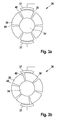
- the DC motor 3 five windings 32, each with respect to a rotor shaft 34 of the rotor 31 opposite Coil elements 33 include.
- a stator 35 of the electric motor 3 has mutually opposite poles 39 of one or more permanent magnets and is arranged around the rotor 31, so that the rotor 31 can rotate about the rotor shaft 34 freely inside the stator 35.
- the DC motor 3 is provided in the present embodiment so that the windings 32 can be electrically contacted by means of a commutator 36.
- the commutator 36 has arranged around the rotor shaft 34 sliding contacts 38, which are each in connection with a winding 32.
- the sliding contacts 38 are electrically isolated from each other by grooves 40. Respective sliding contacts 38 contact one of the windings 32.
- the sliding contacts 38 are contacted with the aid of a pair of brushes 37 with brushes opposite each other with respect to the rotor shaft 34.
- the sliding contacts 38 and the brushes of the brush pair 37 are arranged so that at a certain position of the rotor 31, the brushes of the brush pair 37 contact exactly one winding 32 of the rotor 31.
- the commutator 36 can, as in the FIGS. 3a and 3b is shown to be formed with respect to the rotor 31, the two (in the FIGS. 3a and 3b shown) contacting states, which are alternately occupied during a rotation of the rotor 31.
- rotation state contacted a pair of brushes 37 of the commutator 36 a single winding 32 of the DC motor 3 and the contacting state of the FIG. 3b contacted the brush pair 37 of the commutator 36 two windings 32 of the DC motor 3 via grooves 40 between two adjacent sliding contacts 38 away.
- the brush pair 37 may contact a first number of windings 32 in a contacting state and a second number of windings 32 in a further contacting state.
- the individual windings 32 differ in terms of their complex resistance, so that each winding 32 can be assigned an individual, complex resistance. If it is determined that the differences between the complex resistances of the individual windings 32 are not sufficiently large, then these can be combined with suitable ones passive components are connected to provide each of the windings 32 with an individual complex resistance, which differs from the complex resistance of at least one of the other windings 32.
- the evaluation of the complex resistance of that coil winding 32 of the rotor 31, which is being contacted by the brush pair 37 can thus indicate an indication of the absolute angular position of the rotor 31 of the DC motor 3.
- the complex resistance of one of the coil windings 32 of the electric motor 3 distinguishable from other coil windings 32, for example, a changed position of the coil winding 32 on the armature of the rotor 31, a layering of the coil winding 32, a series connection of the coil winding 32 with a device having a real or complex resistance, a parallel connection of the coil winding 32 are provided with a device with a real and / or complex resistance or the provision of a different magnetically active material inside the coils of the coil windings 32.
- Other measures such. B. a different from the other coil windings 32 number of turns and the like are conceivable, as long as they do not affect the desired operation of the electric motor, in particular not cause an imbalance in the rotor 31 of the DC motor 3.
- the commutator 36 When a particular coil winding 32 is contacted with the adjusted electrical parameter via the commutator 36, the commutator 36 is in a particular commutator position. Since the commutator 36 is fixedly connected to the rotor shaft 34 of the DC motor 3, so that the angular position of the rotor shaft 34 can be determined. Also, several or all coil windings 32 may be provided with different electrical parameters, in particular with different electrical inductances, so that several, in particular twice the number of coil windings 32 corresponding, absolute angular positions of the rotor shaft 34 can be distinguished. In general, the number of sliding contacts 38 determines the possible resolution or the number of detectable angular positions of the rotor shaft 34. By detecting a sequence of oscillation frequencies of the oscillatory circuit resulting from the electrical parameters during operation of the DC motor 3 Furthermore, a direction of rotation of the rotor shaft 34 and its rotational speed can be determined.
- the coil pair 33 currently contacted by the brush pair 37 is detected as follows.
- the resonant circuit resulting from the capacitor 6 and the respectively contacted coil winding or coil windings begins to oscillate, excited by the amplifier 11, and an oscillation frequency is established which corresponds to the resonant frequency of the resonant circuit.
- the resonant frequency of the resonant circuit is determined by the inductance of the inductance between the brushes of the brush pair and the capacitance of the capacitor 6.
- the oscillation signal is tapped and in the frequency counter 17 is determined in accordance with the adjusting oscillation frequency.
- the self-adjusting oscillation frequency is suitably communicated to the microcontroller 4. This can be done in a digital manner as well as by an analog voltage signal whose level indicates the detected frequency.
- an analog-to-digital converter 18 may be provided.
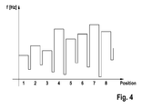
- Fig. 4 is a possible course of the frequencies of the vibration signal in a rotation of the rotor recognizable. It can be seen that, depending on the position of the rotor, a different oscillation frequency is established. There are dips in the oscillation frequency between the regions of the different oscillation frequency when two coil windings of the rotor are contacted simultaneously, which increases the inductance and thus reduces the resonance frequency of the oscillation circuit.
- the profile of an individual electric motor 3 can be taught in, and the self-adjusting resonance frequencies are stored in a corresponding memory unit 16 in the microcontroller 4.
- the respectively adjusting oscillation frequency is compared with the stored in the memory unit 16 oscillation frequencies and in accordance with the measured oscillation frequency with one of the stored in the memory unit oscillation frequencies, the corresponding the stored oscillation frequency associated rotor position is determined and provided or output accordingly.
- the absolute angular position an absolute angular position determined by integrating or otherwise determined by difference values can be cyclically corrected or normalized. As a result, a possible deviation of the actual from the expected angular position is minimized or even eliminated.
Landscapes
- Engineering & Computer Science (AREA)
- Power Engineering (AREA)
- Dc Machiner (AREA)
Applications Claiming Priority (1)
| Application Number | Priority Date | Filing Date | Title |
|---|---|---|---|
| DE102009002907A DE102009002907A1 (de) | 2009-05-07 | 2009-05-07 | Verfahren und Vorrichtung zum Bestimmen einer absoluten Winkellage eines Rotors eines Elektromotors |
Publications (2)
| Publication Number | Publication Date |
|---|---|
| EP2249472A2 true EP2249472A2 (fr) | 2010-11-10 |
| EP2249472A3 EP2249472A3 (fr) | 2017-07-19 |
Family
ID=42668750
Family Applications (1)
| Application Number | Title | Priority Date | Filing Date |
|---|---|---|---|
| EP10156736.0A Withdrawn EP2249472A3 (fr) | 2009-05-07 | 2010-03-17 | Procédé et dispositif de détermination d'une position angulaire absolue d'un rotor d'un moteur électrique |
Country Status (2)
| Country | Link |
|---|---|
| EP (1) | EP2249472A3 (fr) |
| DE (1) | DE102009002907A1 (fr) |
Families Citing this family (1)
| Publication number | Priority date | Publication date | Assignee | Title |
|---|---|---|---|---|
| DE102012208368A1 (de) | 2012-05-18 | 2013-11-21 | Robert Bosch Gmbh | Vorrichtung zum Halten eines Positionsgebers in einem Elektromotor |
Family Cites Families (3)
| Publication number | Priority date | Publication date | Assignee | Title |
|---|---|---|---|---|
| DE4135873C2 (de) * | 1991-10-26 | 2003-01-30 | Brose Fahrzeugteile | Verfahren und Vorrichtung zur Erfassung der Position und Drehrichtung und/oder zur Erfassung dynamischer Kenngrößen von fremdkraftbetätigten Verstellungen eines Verstellobjektes |
| DE102005059862A1 (de) * | 2005-12-15 | 2007-06-28 | Hella Kgaa Hueck & Co. | Gleichstrommotor mit einem Mittel zur Erfassung einer Rotordrehung |
| DE102007013711A1 (de) * | 2007-03-22 | 2008-09-25 | Brose Fahrzeugteile Gmbh & Co. Kommanditgesellschaft, Hallstadt | Verfahren und Vorrichtung zur Dreherfassung eines bürstenbetriebenen Gleichstrommotors |
-
2009
- 2009-05-07 DE DE102009002907A patent/DE102009002907A1/de not_active Ceased
-
2010
- 2010-03-17 EP EP10156736.0A patent/EP2249472A3/fr not_active Withdrawn
Non-Patent Citations (1)
| Title |
|---|
| None |
Also Published As
| Publication number | Publication date |
|---|---|
| DE102009002907A1 (de) | 2010-11-11 |
| EP2249472A3 (fr) | 2017-07-19 |
Similar Documents
| Publication | Publication Date | Title |
|---|---|---|
| EP2105713B1 (fr) | Appareil de mesure de position et son procédé de fonctionnement | |
| EP2130293B1 (fr) | Procédé et dispositif de détection de rotation d'un moteur à courant continu à balais | |
| DE3706659C2 (fr) | ||
| EP0418712B1 (fr) | Capteur de position | |
| DE10156243A1 (de) | Elektronisch kommutierter Motor | |
| EP2474090B1 (fr) | Procédé et dispositif pour déterminer une position de rotor d'une machine synchrone | |
| WO2021094020A1 (fr) | Machine électrique | |
| EP3388803B1 (fr) | Procédé de détection de la température d'enroulement d'un enroulement de moteur | |
| DE10031423B4 (de) | Vorrichtung zur Ermittlung der Drehlage des Rotors einer elektrischen Maschine | |
| EP2249472A2 (fr) | Procédé et dispositif de détermination d'une position angulaire absolue d'un rotor d'un moteur électrique | |
| DE102016204049B4 (de) | Lageerfassungsvorrichtung und Verfahren zum Übertragen eines Nachrichtensignals zwischen relativbeweglichen Gerätekomponenten mittels der Lageerfassungsvorrichtung | |
| EP2266200B1 (fr) | Moteur électrique, système de moteur et procédé de détermination de la position angulaire absolue d'un rotor d'un moteur électrique | |
| DE102008000618A1 (de) | Auswerteeinheit, Motorsystem und Verfahren zur Bestimmung einer Drehzahl eines Elektromotors | |
| EP3707479A1 (fr) | Positionnement de moteurs au moyen d'une mesure capacitive | |
| DE102010001116A1 (de) | Verfahren und Vorrichtung zum Erkennen von in eine elektrische Maschine eingedrungenes Fluid | |
| DE102009002654A1 (de) | Verfahren und Vorrichtung zum Bestimmen einer absoluten Winkellage eines Rotors eines kommutierten Elektromotors | |
| EP3891882B1 (fr) | Dispositif, système et procédé de détermination d'un angle entre un rotor et un stator | |
| WO2021094021A1 (fr) | Machine électrique | |
| DE102020131811A1 (de) | Verfahren zur Steuerung eines Stellantriebs | |
| EP2513725B1 (fr) | Procédé et dispositif permettant de faire fonctionner un appareil de commande destiné à détecter la position de l'induit d'un moteur électrique | |
| WO2023078798A1 (fr) | Ensemble de mesure | |
| WO2021094019A1 (fr) | Machine électrique | |
| EP3549254A1 (fr) | Dispositif et procédé pour déterminer la position du rotor | |
| DE102010063319A1 (de) | Verfahren und Vorrichtung zum Kommutieren eines elektronisch kommutierten Stellantriebs | |
| DE102009028218A1 (de) | Gleichstrommotor zur senorlosen Drehzahlermittlung |
Legal Events
| Date | Code | Title | Description |
|---|---|---|---|
| PUAI | Public reference made under article 153(3) epc to a published international application that has entered the european phase |
Free format text: ORIGINAL CODE: 0009012 |
|
| AK | Designated contracting states |
Kind code of ref document: A2 Designated state(s): AT BE BG CH CY CZ DE DK EE ES FI FR GB GR HR HU IE IS IT LI LT LU LV MC MK MT NL NO PL PT RO SE SI SK SM TR |
|
| AX | Request for extension of the european patent |
Extension state: AL BA ME RS |
|
| PUAL | Search report despatched |
Free format text: ORIGINAL CODE: 0009013 |
|
| AK | Designated contracting states |
Kind code of ref document: A3 Designated state(s): AT BE BG CH CY CZ DE DK EE ES FI FR GB GR HR HU IE IS IT LI LT LU LV MC MK MT NL NO PL PT RO SE SI SK SM TR |
|
| AX | Request for extension of the european patent |
Extension state: AL BA ME RS |
|
| RIC1 | Information provided on ipc code assigned before grant |
Ipc: G01P 3/00 20060101ALI20170614BHEP Ipc: H02P 6/18 20160101AFI20170614BHEP Ipc: H02P 7/00 20160101ALI20170614BHEP Ipc: G01D 5/14 20060101ALI20170614BHEP |
|
| STAA | Information on the status of an ep patent application or granted ep patent |
Free format text: STATUS: THE APPLICATION IS DEEMED TO BE WITHDRAWN |
|
| 18D | Application deemed to be withdrawn |
Effective date: 20180120 |