EP2408533B1 - Verbesserte vorrichtung zur kombinierten gasentfernung, schmutzentfernung und entfernung von kontaminierenden flüssigkeiten - Google Patents
Verbesserte vorrichtung zur kombinierten gasentfernung, schmutzentfernung und entfernung von kontaminierenden flüssigkeiten Download PDFInfo
- Publication number
- EP2408533B1 EP2408533B1 EP10709298.3A EP10709298A EP2408533B1 EP 2408533 B1 EP2408533 B1 EP 2408533B1 EP 10709298 A EP10709298 A EP 10709298A EP 2408533 B1 EP2408533 B1 EP 2408533B1
- Authority
- EP
- European Patent Office
- Prior art keywords
- flow
- liquid
- zone
- removal
- resistance
- Prior art date
- Legal status (The legal status is an assumption and is not a legal conclusion. Google has not performed a legal analysis and makes no representation as to the accuracy of the status listed.)
- Active
Links
Images


Classifications
-
- B—PERFORMING OPERATIONS; TRANSPORTING
- B01—PHYSICAL OR CHEMICAL PROCESSES OR APPARATUS IN GENERAL
- B01D—SEPARATION
- B01D19/00—Degasification of liquids
- B01D19/0042—Degasification of liquids modifying the liquid flow
- B01D19/0047—Atomizing, spraying, trickling
-
- B—PERFORMING OPERATIONS; TRANSPORTING
- B01—PHYSICAL OR CHEMICAL PROCESSES OR APPARATUS IN GENERAL
- B01D—SEPARATION
- B01D21/00—Separation of suspended solid particles from liquids by sedimentation
- B01D21/0039—Settling tanks provided with contact surfaces, e.g. baffles, particles
-
- B—PERFORMING OPERATIONS; TRANSPORTING
- B01—PHYSICAL OR CHEMICAL PROCESSES OR APPARATUS IN GENERAL
- B01D—SEPARATION
- B01D21/00—Separation of suspended solid particles from liquids by sedimentation
- B01D21/0039—Settling tanks provided with contact surfaces, e.g. baffles, particles
- B01D21/0045—Plurality of essentially parallel plates
-
- B—PERFORMING OPERATIONS; TRANSPORTING
- B01—PHYSICAL OR CHEMICAL PROCESSES OR APPARATUS IN GENERAL
- B01D—SEPARATION
- B01D21/00—Separation of suspended solid particles from liquids by sedimentation
- B01D21/0039—Settling tanks provided with contact surfaces, e.g. baffles, particles
- B01D21/0063—Settling tanks provided with contact surfaces, e.g. baffles, particles with cross-flow flow direction of liquid and solid particles
-
- B—PERFORMING OPERATIONS; TRANSPORTING
- B01—PHYSICAL OR CHEMICAL PROCESSES OR APPARATUS IN GENERAL
- B01D—SEPARATION
- B01D21/00—Separation of suspended solid particles from liquids by sedimentation
- B01D21/0087—Settling tanks provided with means for ensuring a special flow pattern, e.g. even inflow or outflow
-
- B—PERFORMING OPERATIONS; TRANSPORTING
- B01—PHYSICAL OR CHEMICAL PROCESSES OR APPARATUS IN GENERAL
- B01D—SEPARATION
- B01D21/00—Separation of suspended solid particles from liquids by sedimentation
- B01D21/24—Feed or discharge mechanisms for settling tanks
- B01D21/245—Discharge mechanisms for the sediments
-
- B—PERFORMING OPERATIONS; TRANSPORTING
- B01—PHYSICAL OR CHEMICAL PROCESSES OR APPARATUS IN GENERAL
- B01D—SEPARATION
- B01D21/00—Separation of suspended solid particles from liquids by sedimentation
- B01D21/24—Feed or discharge mechanisms for settling tanks
- B01D21/2494—Feed or discharge mechanisms for settling tanks provided with means for the removal of gas, e.g. noxious gas, air
-
- B—PERFORMING OPERATIONS; TRANSPORTING
- B01—PHYSICAL OR CHEMICAL PROCESSES OR APPARATUS IN GENERAL
- B01D—SEPARATION
- B01D2221/00—Applications of separation devices
- B01D2221/02—Small separation devices for domestic application, e.g. for canteens, industrial kitchen, washing machines
Definitions
- the present invention relates to a removal device for removing air, gas or micro bubbles, particles of a contaminating liquid and/or and dirt from a liquid in a closed liquid conduit system. These devices are known in the field of the art.
- gasses are removed from the liquid in the conduit system. These gasses generally occur as free gasses or absorbed by the liquid. This is in particular important in conduits for heating systems, but may also be important in other situations. For this purpose, gas removal devices have been developed.
- dirt parts are removed from the liquid inside the conduit system. These dirt parts may come loose from the inner walls of the conduits. Due to the flow of the liquid inside the conduit system, the dirt particles may be held in suspension.
- dirt parts are not removed, they may clog up the conduit system or damage certain components in the conduit system, such as pumps.
- particles of other liquids may contaminate the main liquid in a conduit system.
- the contaminating liquid may be lighter or heavier than the main liquid.
- a combined gas removal and dirt removal device is known from WO97/10037 .
- This device has a gas removal element and a quiet zone below the gas removal element. In the quiet zone, dirt should come to rest and settle on the bottom.
- a problem associated with the device of WO97/10037 is that the dirt removal function does not work very well.
- the liquid does not become calm enough to allow dirt parts or particles from a heavy contaminating liquid to settle.
- the liquid has a substantial speed. This speed needs to be substantially reduced in the quiet zone, in order to allow the dirt parts or particles from a heavy contaminating liquid to settle. It is in particular difficult to remove the smaller particles under 50 microns from the liquid. Another requirement is that a substantial discharge should be directed through the quiet zone, because otherwise the part of the flow which is cleaned is too small to affect the dirt level or level of particles from a heavy contaminating liquid in the total flow.
- the device of WO97/10037 does not succeed enough in reducing the velocity of the liquid at any acceptable resistance of flow.
- the dirt parts or particles from a heavy contaminating liquid are substantially held in suspension and do not settle to the bottom of the quiet zone.
- the flow of the liquid remains substantially turbulent, i.e. variable in time, which further contributes to the dirt particles or particles from a heavy contaminating liquid being held in suspension.
- a possible solution could be to substantially increase the size of the quiet zone.
- a device of limited size is desired in the field, for cost reasons and also because devices of limited size are more practical during installation.
- a substantial increase in the size of the apparatus would lead to an apparatus of impractical size.
- DE4017229 further discloses a device for removing contaminations from liquids in a liquid conduit system.
- the device of DE4017229 also does not provide satisfactory results. Rather than to settle to the bottom, the dirt tends to be conveyed with the main flow through the device. The gas bubble also tend to be conveyed through the device, rather than to be removed.
- the device according to DE4017229 is also quite large, which is not very practical in many situations.
- Removal devices for removing gas and/or dirt and/or particles from a contaminating liquid are known from WO97/10037 , DE4017229 , EP0001866 , and US2007/0256964 .
- the invention provides a removal device according to claim 1.
- the quiet zone has a separate entrance and exit, a relatively calm and stable flow pattern is achieved. Substantially low velocities are possible, resulting in relatively effective dirt removal or removal of particles of a relatively heavy contaminating liquid and /or effective rising of gas bubbles or rising of particles of a relatively light contaminating liquid.
- the branch flow into the quiet zone will have a different direction than a main ongoing flow.
- the branch flow is oriented at right angles to the main ongoing flow.
- the main ongoing flow may be oriented horizontally, while the branch flow may be oriented substantially vertically.
- the removal device comprises both a quiet zone for dirt removal and removal of particles of a relatively heavy contaminating liquid and a quiet zone for gas removal and removal of particles of a relatively heavy contaminating liquid.
- a single combined resistance zone may be provided for both the quiet zone for dirt removal and the quiet zone for gas removal.
- each quiet zone has a respective resistance zone.
- the present invention may also be used to clean contaminated liquids, wherein the contamination relates to other liquids.
- thermal oil may be cleaned which comprises volatile components.
- Thermal oil is used in heating systems, often in situations wherein the working temperature is above 100 degrees Celsius. In such a situation, the use of water would require high pressures and devices capable of handling such high pressures. With thermal oil, substantially lower pressures can be used in these temperature ranges.
- US5820648 and GB2375056 disclose systems for cleaning such thermal oil.
- these systems include a vaporisation chamber for the main liquid, i.e. the thermal oil, a condenser and other substantially complicated parts. These parts make the systems as a whole quite complex and cumbersome.
- the present invention provides a much simpler solution, i.e. without a vaporisation chamber for the main liquid.
- the relatively light component may a volatile contaminant in thermal oil, or a different contaminating liquid in a different main liquid.
- the removal device comprises a quiet zone for dirt removal or removal of particles of a relatively heavy contaminating liquid, wherein the flow guides in the quiet zone define:
- the removal device comprises a quiet zone for the rising of gas bubbles or rising of particles of a relatively light contaminating liquid, wherein the flow guides in the quiet zone define:
- the one or more return openings when viewed from above the one or more return openings substantially form an annulus which extends substantially around the bifurcation opening, wherein the flow guides separate the one or more return openings from the bifurcation opening.
- the flow guides define an entrance flow section from the bifurcation point into the quiet zone, wherein the cross-sectional area of the entrance flow section increases in the direction of flow.
- the flow guides define one or more return flow sectional from the quiet zone to the merge point, wherein the cross-sectional area of the one or more return flow section increases in the direction of flow.
- Bernoulli's principle dictates that a decrease in velocity results in an increase in hydrostatical pressure.
- the hydrostatical pressure in the resistance zone is higher than in the approach zone and in the leaving zone. This results in the forming of the flow through the quiet zone, i.e. the flow enters the quiet zone from the resistance zone where the hydrostatical pressure is high. The flow flows through the quiet zone and into the approach zone or leaving zone where the hydrostatical pressure is relatively low.
- the resistance zone when viewed from above the resistance zone comprises:
- the resistance zone when viewed from above the resistance zone is substantially rhombic, wherein one corner of the rhombus form is substantially directed at the supply opening and another corner is substantially directed at the discharge opening.
- the one or more resistance members are bubble-forming members which comprise a relatively large surface area onto which gasses in the liquid may attach and form bubbles.
- the removal device comprises a plurality of return openings, wherein at least one return opening is provided upstream of the bifurcation point and wherein at least one return opening is provided downstream of the bifurcation point.
- the removal device comprises one or more return openings, wherein the one or more return opening is only provided downstream of the bifurcation point.
- the present invention also relates to a method for:
- the present invention may also be referred to as a combined gas and dirt and contaminating liquid remover.
- FIG. 1 - 4 , 9 and 10 a combined air and dirt and contaminating liquid removal device 10 according to the invention is shown. Wherever the word "air” is used, it will be understood that other gasses may also be removed.
- the device 10 comprises a housing 12, a liquid entrance 14 and a liquid exit 16.
- the liquid entrance 14 and the liquid exit 16 are constructed such that the device can be mounted in-line in a liquid conduit system (not shown).
- the entrance 14 goes over in a supply opening 15 in the housing 12 via a tube 11.
- the exit 16 goes over in a discharge opening 17 in the housing 12 via a tube 11.
- the housing defines an inner space 13.
- the surface area of the housing is larger than the surface area of the tubes 11.
- a dirt exit 20 is provided at a bottom side 18 of the device 10.
- the dirt exit 20 comprises a valve (not shown) configured to be opened and closed.
- the bottom side 18 is substantially conical, such that the bottom side 18 slopes toward the dirt exit 20.
- the dirt exit 18 can also be used for removing particles of a relatively heavy contaminating liquid.
- an air outlet 24 is provided which is constructed to enable air to be released from the device 10.
- the air outlet 24 may also be capable of enabling particles of a relatively light contaminating liquid to be released.
- a tap may be provided.
- Other outlets may also be used.
- the device 10 has a substantially circular form, when viewed in top view. Other forms are also possible.
- a side wall 26 of the device 10 is substantially circular.
- the supply opening 15 and the discharge opening 17 are provided in the side wall 26.
- the air and dirt removal unit 30 is provided inside the housing 12.
- the air and dirt removal unit 30 comprises a holder 32 which is a cage-like structure having open walls 37.
- the holder 32 defines a resistance zone 31.
- the holder 32 has a substantially rhombic shape, as can be seen in Figure 4 .
- the holder 32 comprises a plurality of air removal members 33. These may be O-rings or be a different form of members. These members are known in the prior art.
- the air and dirt removal unit is also configured for removing contaminating liquids.
- the open walls 37 may be manufactured from wire mesh.
- the members 33 are made from a metal and have a relatively large surface area, such that in use gasses may attach to the surface of the air removal members 33.
- a single air removal element is provided which can be mounted in the housing as a single object, for instance, a spiral form or a form comprising a plurality of spirals.
- the holder 32 has side walls 37.
- the side walls 37 define the rhombic shape.
- the rhombic form has four corners 50. One corner 50 is directed at the supply opening 15. One corner 50 is directed at the discharge opening 17.
- Flow guides 34 are provided below the holder 32. Also, flow guides 34 are provided above the holder 32. The flow guides 34 are connected at an upper edge 35 thereof to a lower edge 36 of the holder 32. The flow guides 34 are plate-like structures.
- the flow guides 34 below the resistance zone 31 define a bifurcation opening 25 at the underside 27 of the resistance zone 31.
- the flow guides 34 above the resistance zone define a bifurcation opening 25 at the upper side 29 of the resistance zone 31.
- Figure 4 shows that the flow guides 34 taper.
- Four openings 42 are defined between a lower edge 38 of the flow guides 34 and the side wall 26.
- the openings 42 have a form of a gap.
- the flow guides 34 taper outwardly as can also be see better in Figure 10 .
- a lower edge 38 of the flow guides 34 is provided at a distance 39 from the bottom side 18 of the housing 12. Between the lower edge 38 and the bottom side 18, a lower quiet zone 40 is defined. Above the upper edge38 of the upper flow guides 34, an upper quiet zone 40 is defined.
- the flow guides 34 further have cut-off corners 45, resulting in vertical edges 46 which fit to the side wall 26 of the housing 12.
- Closure members 48 may be provided at corners 50 to prevent any flow from circumventing the resistance zone 31.
- the closure members 48 fit with the inner wall 26 of the housing 12.
- the closure members 48 extend between a lower point 47 where two ridges 46 of flow guides 34 meet and an upper point 47 where two ridges 46 from flow guides 34' meet.
- closure members 48 are provided. In this embodiment, a gap exists between the resistance zone 31 and the wall 26. Thus, a possibility exists for the flow to flow around the resistance zone 31.
- the closure member 48 is included. In figures 6 , 7 , 8 , 9 , 10 , 13 .the closure members are left out.
- FIG. 7 and 8 A second embodiment is shown in Figures 7 and 8 .
- the resistance zone 31 is extended upwards and the flow guides 34' are omitted.
- the embodiment of Figures 7 and 8 is the same as the embodiment of Figures 5 and 6 .
- This embodiment has a better air removal function as the embodiment of Figures 1-6 because the surface area of the flow through the resistance zone 31 is greater.
- the velocity of the liquid inside the resistance zone 31 is lower and the air has more time to form bubbles.
- Particles of a relatively light contaminating liquid also have time to form bubbles.
- a flow of liquid enters the device 10 via the entrance 14. Via the tube 11 and the supply opening 15, the liquid enters the inner space 13 defined by the housing 12.
- FIG. 12 Inside the housing 12, the flow widens in a vertical sense as can be seen in Figures 5 and 7 .
- an approach zone 62A, B is present between the supply opening 15 and an entry side 64 of the holder 32.
- the approach zone 62 comprises a left section 62A and a right section 62B, dividing the flow in a left part and a right part.
- the resistance zone 31 comprises a widening part 80 in which the cross-sectional area of the flow increases in the direction of the flow, and a narrowing part 82 in which the cross-sectional area of the flow decreases in the direction of the flow.
- the widening part 80 is the left part of the rhombic shape and the narrowing part 82 is the right part of the rhombic shape.
- a leaving zone 55 is present between an exit side 66 of the resistance zone 31 and the discharge opening 17.
- the leaving zone also comprises a left part 55A and a right part 55B.
- the liquid enters the approach zone 62 through the supply opening 15. From the approach zone 62, the liquid enters the resistance zone 31 defined by the holder 32 through the open wall 37. In the resistance zone 31, the air and other gasses and particles of a relatively light contaminating liquid which are present in the liquid attach to the O-rings 33. The air forms bubbles, which grow. When the bubbles have reached a certain size, they come loose from the O-rings 33 and rise to the upper end 22 of the device 10. The air bubbles eventually leave the device 10 via the valve 24.
- a floater (not shown) may be present with a lever in order to open the valve 24 when required. These floaters and levers are known in the field of the art.
- the downward flow 65 subsequently enters the quiet zone 40.
- the velocity of the liquid substantially drops.
- the liquid substantially comes to a rest.
- the part of the main flow 60 which is diverted downward into the quiet zone is relatively small. Therefore, the discharge of the diverted flow 65 is relatively small and the velocity of the liquid thus is also relatively small.
- dirt particles or particles of a relatively heavy contaminating liquid settle on the bottom 18 of the housing. From there, the dirt parts or particles of a relatively heavy contaminating liquid slide over the bottom wall 18 to the dirt exit 20. In use, the dirt exit 20 will remain closed for a greater portion of time. Periodically, the dirt exit 20 will be opened and the dirt is removed.
- liquid conduit systems are closed loop systems, and the liquid will pass through the combined air and dirt remover 10 periodically. If a portion of the dirt parts is removed each time the liquid makes a complete round, then it is also possible to keep the liquid substantially clean.
- the flow After passing the quiet zone 40, the flow is directed upwardly and outwardly, toward the side wall 26 of the housing 12. The flow passes through the openings 42 between the flow guides 34 and the side wall 26.
- the flow is now an upward flow 70 and flows back to the approach zone 62 and/or the leaving zone 55.
- the diverted flow merges with the main flow 60.
- the removal device according to the invention can be installed in both directions.
- the liquid entrance 14 and the liquid exit 16 are interchangeable.
- the part of the diverted flow that merges with the main flow in the leaving zone 55 subsequently leaves the device 10 through the discharge opening 17.
- the part of the diverted flow that merges with the main flow in the approach zone 62 re-enters the resistance zone 31.
- a part of the flow may be again diverted into the quiet zone 40 and thus enter the quiet zone 40 for a second time. However, a greater portion of the flow will flow through the resistance zone 31 into the leaving zone 55 and through the discharge opening 17 out of the device 10.
- another branch-off flow 65 flows upward.
- the upper branch-off flow flows into the upper quiet zone 40.
- the upper branch-of flow comes to rest.
- Gas bubbles or particles of a relatively light contaminating liquid which are formed in the resistance zone 31 are conveyed with the upper branch-off flow 65 and move upward into the quiet zone.
- the gas bubbles or particles of a relatively light contaminating liquid continue to rise due to their buoyancy and move toward the upper end 22 and gas exit 24 of the removal device 10.
- the tapering arrangement of the flow guides 34 is shown.
- the bifurcation opening 25 is defined.
- the bifurcation opening 25 has a diameter D1.
- the flow guides 34 taper outwardly in the direction of the branch-off flow 65 and defines a downward flow section 84.
- the downward flow section has a diameter D2, which is substantially greater than D1. This outward tapering causes the velocity of the flow 65 to decrease, resulting in a low velocity in the quiet zone. Thus, dirt particles or particles of a relatively heavy contaminating liquid may settle.
- a return flow section 86 In a return flow section 86, a same effect is created.
- the return openings 42 are relatively narrow and define a return flow section 86 having a diameter D3.
- the return flow section 86 At the upper end of the return flow section 86 the return flow section 86 has a diameter D4 which is substantially greater than the diameter D3.
- the merge point 88 is defined.
- the return flow section 85 has an annular shape.
- the bottom quiet zone is a compartment which is substantially separated from the resistance zone by the bottom wall of the resistance zone.
- the upper quiet zone is a compartment which is substantially separated from the resistance zone by an upper wall of the resistance zone.
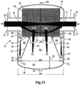
- FIG. 13 another embodiment of the invention is shown.
- This air, dirt and contaminating liquid removal device 10 is integrated with a hydraulic separator 90.
- the hydraulic separator 90 is to be fitted between a primary liquid circuit (not shown) and a secondary liquid circuit (not shown), in such a manner that the first and secondary liquid circuits are hydraulically independent.
- the hydraulic separator 90 has an elongate, preferably vertically positioned body 92 with an internal space 91 which is delimited by a wall 93.
- the air, dirt and contaminating liquid removal device 10 comprises a first supply opening 96 constructed to be connected to a primary liquid circuit (not shown), and a first discharge opening 97 constructed to be connected to a secondary liquid circuit (not shown).
- the air, dirt and contaminating liquid removal device 10 further comprises a second discharge opening 94 configured to be connected to the primary liquid circuit and a second supply opening 95 configured to be connected to the secondary liquid circuit.
- the first supply opening 96 and the second discharge opening 94 are located substantially on one longitudinal side 98 of the hydraulic separator 90.
- the first discharge opening 97 and the second supply opening 95 are located substantially on an opposite longitudinal side 99 of the hydraulic separator 90.
- the first supply opening 96 and the first discharge opening 97 are located at a first height region 100 of the hydraulic separator 10.
- the second discharge opening 94 and the second supply opening 95 are located substantially at a second, different height region 102 of the hydraulic separator 90.
- an air removal unit 30A is provided in the first region 100.
- a first quiet zone 40A is provided for the removal of air, gas and particles of a relatively light contaminating liquid via the air outlet 24.
- the air removal unit 30A only has flow guides 34 at the upper side thereof. In an alternative embodiment, flow guides 34 may also be provided at the lower side thereof.
- a dirt removal unit 30B is provided in the second region 102.
- a second quiet zone 40B is provided for the removal of dirt or particles of a relatively heavy contaminating liquid.
- the dirt removal unit 30B only has flow guides 34 at the lower side thereof. In an alternative embodiment, flow guides 34 may also be provided at the upper side thereof. side thereof. In an alternative embodiment, flow guides 34 may also be provided at the upper side thereof.
- a first flow 60A will flow through the first resistance zone 31A.
- air and other gasses or particles of a relatively light contaminating liquid which are present in the liquid attach to the O-rings 33.
- the air forms bubbles, which grow.
- the bubbles have reached a certain size, they come loose from the O-rings 33.
- a branch-off flow 65 flows upward into the first quiet zone 40A.
- the upper branch-off flow comes to rest. Gas bubbles or bubbles of a light contaminating liquid which are formed in the first resistance zone 31A are conveyed with the upper branch-off flow 65 and move upward into the first quiet zone 40A and to the air outlet 24.
- a second flow 60B will flow through the second resistance zone 31B, and a second branch flow 65B will flow into the second quiet zone 40B. Dirt or particles of a relatively heavy contaminating liquid will settle in the second quiet zone 40B and may be removed via the dirt outlet 20.
Landscapes
- Chemical & Material Sciences (AREA)
- Chemical Kinetics & Catalysis (AREA)
- Health & Medical Sciences (AREA)
- Toxicology (AREA)
- Degasification And Air Bubble Elimination (AREA)
- Gas Separation By Absorption (AREA)
Claims (10)
- Entfernungsvorrichtung (10) zum Entfernen von Gas und/oder Schmutz und/oder Partikeln einer kontaminierenden Flüssigkeit aus einer Flüssigkeit in einem Flüssigkeitsleitungssystem, wobei die Entfernungsvorrichtung Folgendes umfasst:- ein Gehäuse (12), das einen Innenraum (13) definiert, wobei das Gehäuse eine Seitenwand (26) umfasst,- eine Zuführöffnung (15) und eine Abführöffnung (17), die in einer Linie auf gegenüberliegenden Seiten des Gehäuses in der Seitenwand des Gehäuses bereitgestellt sind,- eine Widerstandszone (31) in dem Innenraum zwischen der Zuführöffnung und der Abführöffnung, wobei die Widerstandszone einen Eingang und einen Ausgang und ein oder mehrere Strömungswiderstandselemente umfasst, wobei die Widerstandszone im Gebrauch einen hydraulischen Widerstand für eine Hauptströmung bereitstellt, die von der Zuführöffnung durch die Widerstandszone zu der Abführöffnung fließt,- zumindest eine Ruhezone (40) im Innenraum unter und/oder über der Widerstandszone, in der die Flüssigkeit im Gebrauch eine wesentlich geringere Geschwindigkeit als in der Widerstandszone hat, wobei die zumindest eine Ruhezone:a) unter der Widerstandszone angeordnet ist und so konfiguriert ist, dass sich Schmutz oder Partikel einer relativ schweren kontaminierenden Flüssigkeit auf einem Boden des Gehäuses absetzen können, und/oderb) über der Widerstandszone angeordnet ist und so konfiguriert ist, dass Gasblasen oder Partikel einer relativ leichten kontaminierenden Flüssigkeit zu einem oberen Ende des Gehäuses aufsteigen können,- zumindest eine Bifurkationsöffnung (25) in der Widerstandszone, wobei die Bifurkationsöffnung in Flüssigkeitsverbindung mit der Ruhezone steht und einen Eintritt für eine Verzweigungsströmung in die Ruhezone ermöglicht,- zumindest eine Rückführöffnung (42) zwischen der Ruhezone und einem Zusammenführungspunkt in der Hauptströmung stromaufwärts und/oder stromabwärts von der Widerstandszone, wobei die Rückführöffnung eine Rückführung der Verzweigungsströmung in die Hauptströmung ermöglicht, so dass im Gebrauch die Verzweigungsströmung durch die Bifurkationsöffnung in die Ruhezone eintritt, in der Ruhezone im Wesentlichen zur Ruhe kommt, damit sich Schmutz oder Partikel einer relativ schweren kontaminierenden Flüssigkeit absetzen oder Gasblasen oder Partikel einer relativ leichten kontaminierenden Flüssigkeit aufsteigen können, und nachfolgend durch die Rückführöffnung in die Hauptströmung am Zusammenführungspunkt zurückkehrt,wobei Strömungsführungen (34) in dem Gehäuse bereitgestellt sind, die die zumindest eine Bifurkationsöffnung und die zumindest eine Rückführöffnung definieren und die im Wesentlichen ein Strömungsmuster der Flüssigkeit durch die eine oder mehrere Ruhezonen bestimmen,wobei die Strömungsführungen zumindest eine separate Bifurkationsöffnung und zumindest eine separate Rückführöffnung definieren,wobei die Strömungsführungen Platten sind, die in dem Innenraum angebracht sind und sich von dem Bifurkationspunkt in Strömungsrichtung nach außen verjüngen,wobei die Strömungsführungen (34) die Bifurkationsöffnung (25) in die Ruhezone zur Schmutzabfuhr oder Abfuhr einer relativ schweren kontaminierenden Flüssigkeit an einer Unterseite (27) der Widerstandszone (31) definieren, und/oder die Strömungsführungen (34) die Bifurkationsöffnung (25) in die Ruhezone zum Aufsteigen von Gasblasen oder Aufsteigen von Partikeln einer leichten kontaminierenden Flüssigkeit an einer Oberseite (29) der Widerstandszone (31) definieren,wobei die Strömungsführungen die zumindest eine Rückführöffnung zwischen einer Kante der Strömungsführungen und der Seitenwand des Gehäuses definieren,wobei:- die Strömungsführungen der Ruhezone zur Schmutzentfernung oder zur Entfernung von Partikeln einer relativ schweren kontaminierenden Flüssigkeit eine Unterkante aufweisen, die einem Boden des Gehäuses beabstandet ist, so dass die Ruhezone unterhalb der Unterkante der Strömungsführungen definiert ist und/oder- die Strömungsführungen der Ruhezone zum Aufsteigen von Gasblasen oder Aufsteigen von Partikeln einer relativ leichten kontaminierenden Flüssigkeit eine Oberkante aufweisen, die von einem oberen Ende des Gehäuses beabstandet ist, so dass die Ruhezone für die Blasen oberhalb der Oberkante der Strömungsführungen definiert ist.
- Entfernungsvorrichtung nach Anspruch 1, umfassend sowohl:- eine Ruhezone zur Schmutzentfernung oder zur Entfernung einer schweren kontaminierenden Flüssigkeit und- eine Ruhezone für die Gasentfernung oder die Entfernung einer leichten kontaminierenden Flüssigkeit, wobei eine einzige Widerstandszone (31) sowohl für die Ruhezone für die Schmutzentfernung oder die Entfernung einer schweren kontaminierenden Flüssigkeit als auch für die Ruhezone für die Gasentfernung oder die Entfernung einer leichten kontaminierenden Flüssigkeit bereitgestellt wird.
- Entfernungsvorrichtung nach Anspruch 2, wobei die Ruhezone für die Schmutzentfernung oder die Entfernung einer schweren kontaminierenden Flüssigkeit unterhalb der Widerstandszone angeordnet ist und wobei die Ruhezone für die Gasentfernung oder die Entfernung einer leichten kontaminierenden Flüssigkeit oberhalb der Widerstandszone angeordnet ist.
- Entfernungsvorrichtung nach Anspruch 1, umfassend eine Ruhezone für die Schmutzentfernung oder die Entfernung einer schweren kontaminierenden Flüssigkeit, wobei die Strömungsführungen in der Ruhezone Folgendes definieren:- einen oder mehrere abwärts gerichtete Strömungsabschnitte (65), die an dem Bifurkationspunkt beginnen und in denen die Strömung nach unten gerichtet ist,- einen oder mehrere aufwärts gerichtete Strömungsabschnitte (70), die im Gebrauch eine aufwärts gerichtete Strömung aufweisen und die am Zusammenführungspunkt enden, in der Weise, dass im Gebrauch die Flüssigkeit zur Schmutzentfernung oder Entfernung einer schweren kontaminierenden Flüssigkeit durch den abwärts gerichteten Strömungsabschnitt in die Ruhezone eintritt und die Ruhezone zur Schmutzentfernung oder Entfernung einer stark kontaminierenden Flüssigkeit durch den aufwärts gerichteten Strömungsabschnitt verlässt.
- Entfernungsvorrichtung nach Anspruch 1, umfassend eine Ruhezone für das Aufsteigen von Gasblasen oder das Aufsteigen von Partikeln einer leichten kontaminierenden Flüssigkeit, wobei die Strömungsführungen in der Ruhezone Folgendes definieren:- einen oder mehrere aufwärts gerichtete Strömungsabschnitte (65), die an der Verzweigungsstelle beginnen und im Gebrauch eine aufwärts gerichtete Strömung aufweisen,- einen oder mehrere abwärts gerichtete Strömungsabschnitte (70), die im Verwenden eine abwärts gerichtete Strömung aufweisen und die am Zusammenführungspunkt enden,in der Weise, dass im Gebrauch die Flüssigkeit in die Ruhezone für das Aufsteigen von Gasblasen oder das Aufsteigen von Partikeln einer leichten kontaminierenden Flüssigkeit durch den aufwärts gerichteten Strömungsabschnitt eintritt, in der Ruhezone zur Ruhe kommt und nachfolgend die Ruhezone durch den abwärts gerichteten Strömungsabschnitt verlässt.
- Entfernungsvorrichtung nach Anspruch 1, wobei das eine oder die mehreren Widerstandselemente blasenbildende Elemente sind, die eine relativ große Oberfläche umfassen, an der sich Gase in der Flüssigkeit anlagern und Blasen bilden können.
- Entfernungsvorrichtung nach Anspruch 1, umfassend eine Vielzahl von Rückführöffnungen, wobei zumindest eine Rückführöffnung stromaufwärts des Bifurkationspunktes bereitgestellt ist und wobei zumindest eine Rückführöffnung stromabwärts des Bifurkationspunktes bereitgestellt ist.
- Entfernungsvorrichtung nach Anspruch 1, umfassend eine oder mehrere Rückführöffnungen, wobei die eine oder mehreren Rückführöffnungen nur stromabwärts der Bifurkationsöffnung bereitgestellt sind.
- Entfernungsvorrichtung nach Anspruch 1, die mit einem hydraulischen Separator integriert ist, wobei die Entfernungsvorrichtung umfasst:- - eine erste Abführöffnung (97), die so konfiguriert ist, dass sie mit einer sekundären Schaltung für Flüssigkeiten verbunden werden kann- eine erste Zuführöffnung (96), die so konfiguriert ist, dass sie mit einem primären Flüssigkeitskreislauf verbunden werden kann,- eine zweite Abführöffnung (94), die so konfiguriert ist, dass sie mit dem primären Flüssigkeitskreislauf verbunden werden kann,- eine zweite Zuführöffnung (95), die so konfiguriert ist, dass sie mit dem sekundären Flüssigkeitskreislauf verbunden werden kann.- eine erste Widerstandszone (30A), die zwischen der ersten Zuführöffnung und der ersten Abführöffnung positioniert ist, wobei die erste Widerstandszone im Gebrauch einen hydraulischen Widerstand für einen Hauptstrom bereitstellt, der von der ersten Zuführöffnung durch die erste Widerstandszone zu der ersten Abführöffnung fließt, und- eine zweite Widerstandszone (30B), die zwischen der zweiten Zuführöffnung und der zweiten Abführöffnung positioniert ist, wobei die zweite Widerstandszone im Gebrauch einen hydraulischen Widerstand für eine Hauptströmung bereitstellt, die von der zweiten Zuführöffnung durch die zweite Widerstandszone zu der zweiten Abführöffnung fließt,wobei zumindest eine erste Ruhezone (40A) oberhalb der ersten Widerstandszone bereitgestellt ist, um Gasblasen oder Partikel einer leichten kontaminierenden Flüssigkeit zu einem oberen Ende des Gehäuses aufsteigen zu lassen, undwobei zumindest eine zweite Ruhezone (40B) unterhalb der zweiten Widerstandszone bereitgestellt ist, damit sich Schmutz oder Partikel einer schweren kontaminierenden Flüssigkeit an einem unteren Ende des Gehäuses absetzen können.
- Verfahren zum:a) Entfernen von Luft und/oder Partikeln einer relativ leichten kontaminierenden Flüssigkeit aus einer Flüssigkeit in einem Flüssigkeitsleitungssystem und/oderb) Entfernen von Schmutz und/oder Partikeln einer relativ schweren kontaminierenden Flüssigkeit aus der Flüssigkeit in dem Flüssigkeitsleitungssystem,wobei das Verfahren ein Bereitstellen einer Entfernungsvorrichtung (10) gemäß Anspruch 1 und ein Leiten eines Flüssigkeitsstroms durch die Entfernungsvorrichtung umfasst.
Applications Claiming Priority (2)
| Application Number | Priority Date | Filing Date | Title |
|---|---|---|---|
| NL2002648A NL2002648C2 (en) | 2009-03-20 | 2009-03-20 | Improved combined gas removal and dirt removal device. |
| PCT/NL2010/000047 WO2010107304A1 (en) | 2009-03-20 | 2010-03-18 | Improved combined gas removal, dirt removal and contaminating liquid removal device |
Publications (2)
| Publication Number | Publication Date |
|---|---|
| EP2408533A1 EP2408533A1 (de) | 2012-01-25 |
| EP2408533B1 true EP2408533B1 (de) | 2023-10-11 |
Family
ID=42272440
Family Applications (1)
| Application Number | Title | Priority Date | Filing Date |
|---|---|---|---|
| EP10709298.3A Active EP2408533B1 (de) | 2009-03-20 | 2010-03-18 | Verbesserte vorrichtung zur kombinierten gasentfernung, schmutzentfernung und entfernung von kontaminierenden flüssigkeiten |
Country Status (7)
| Country | Link |
|---|---|
| US (1) | US8313658B2 (de) |
| EP (1) | EP2408533B1 (de) |
| DK (1) | DK2408533T3 (de) |
| FI (1) | FI2408533T3 (de) |
| NL (1) | NL2002648C2 (de) |
| PL (1) | PL2408533T3 (de) |
| WO (1) | WO2010107304A1 (de) |
Families Citing this family (12)
| Publication number | Priority date | Publication date | Assignee | Title |
|---|---|---|---|---|
| DE202010013096U1 (de) * | 2010-12-10 | 2012-03-12 | Technische Universität Chemnitz | Hydraulische Weiche |
| WO2012112049A1 (en) * | 2011-02-17 | 2012-08-23 | Flamco B.V. | Improved removal device for micro-bubbles and dirt particles |
| US9427680B2 (en) | 2011-04-15 | 2016-08-30 | Flamco B.V. | Removal device in particular for micro-bubbles, volatile compounds and dirt |
| NL2006887C2 (en) * | 2011-06-01 | 2012-12-04 | Flamco Bv | Removal device for dirt particles and/or gas bubbles. |
| US9884270B2 (en) * | 2012-01-11 | 2018-02-06 | Flamco B.V. | Removal device |
| FR3003768B1 (fr) * | 2013-03-26 | 2016-07-29 | Optomesures | Systeme de degazage d'un liquide. |
| CA2977663A1 (en) * | 2015-02-27 | 2016-09-01 | Recovered Energy, Inc. | Liquid refinement |
| US10343088B2 (en) | 2015-02-27 | 2019-07-09 | Recovered Energy, Inc. | Liquid refinement |
| US10343089B2 (en) | 2015-02-27 | 2019-07-09 | Recovered Energy, Inc. | Liquid refinement |
| US10399029B1 (en) * | 2016-04-15 | 2019-09-03 | Kealin Chase Hiracheta | Dual phase sand and water separator system and method of use |
| US10819944B2 (en) | 2016-12-16 | 2020-10-27 | Seagate Technology Llc | Mobile wireless drive storage for mobile phone used as car dashboard camera |
| NL2020167B1 (en) * | 2017-12-22 | 2019-07-01 | Flamco Bv | Assembly for cleaning and/or protecting a liquid conduit system |
Citations (5)
| Publication number | Priority date | Publication date | Assignee | Title |
|---|---|---|---|---|
| EP0001866A1 (de) * | 1977-10-31 | 1979-05-16 | Ballast-Nedam Groep N.V. | Vorrichtung zum Abscheiden von suspendiertem Material aus einer Flüssigkeit mittels Schwerkraft |
| WO2000026141A1 (de) * | 1998-11-02 | 2000-05-11 | Hans Huber Gmbh Maschinen- Und Anlagenbau | Kompaktanlage für die mechanische reinigung von abwasser |
| US20040055950A1 (en) * | 2002-09-20 | 2004-03-25 | Bryant Graham John | Apparatus for trapping floating and non-floating particulate matter |
| US20050155925A1 (en) * | 2004-01-21 | 2005-07-21 | Thrush Co., Inc. | Apparatus for removing air and/or debris from a flow of liquid |
| US20070256964A1 (en) * | 2004-04-16 | 2007-11-08 | Nijhus Water Technology B.V. | Separator Device |
Family Cites Families (11)
| Publication number | Priority date | Publication date | Assignee | Title |
|---|---|---|---|---|
| JPS5421801Y2 (de) * | 1976-07-12 | 1979-08-01 | ||
| US4802978A (en) * | 1987-02-27 | 1989-02-07 | Mctighe Industries, Inc. | Oil-water separator |
| DE4017229A1 (de) * | 1989-06-08 | 1990-12-13 | Hydac Technology Gmbh | Vorrichtung zum reinigen von fluessigkeiten durch abscheidung der verunreinigungen |
| ATE231287T1 (de) | 1991-09-30 | 2003-02-15 | Canon Kk | Verfahren für anodische bindung mit lichtstrahlung |
| US5518610A (en) * | 1995-02-07 | 1996-05-21 | Triton Environmental Corporation | Oil-water separation |
| US5858252A (en) * | 1995-08-08 | 1999-01-12 | Darcy; Harold J. | Liquid purification system |
| EP0859655B1 (de) * | 1995-09-11 | 2000-01-19 | Stücklin & Cie AG | Wasserkonditionierungsvorrichtung zur entgasung und/oder entschlammung von wasser in leitungen |
| GB0101917D0 (en) | 2001-01-25 | 2001-03-07 | Franklin Richard G J | Improvements relating to oil decontamination and method therefor |
| US7008546B2 (en) * | 2003-01-07 | 2006-03-07 | Jerry M Edmondson | Oil, water and gas separator for swaying service |
| US7287651B2 (en) * | 2004-09-16 | 2007-10-30 | Vortox Company | Fuel and water separator |
| US7083736B1 (en) * | 2005-02-02 | 2006-08-01 | Gene Hirs | Oil separator |
-
2009
- 2009-03-20 NL NL2002648A patent/NL2002648C2/en active
-
2010
- 2010-02-18 US US12/708,035 patent/US8313658B2/en active Active
- 2010-03-18 PL PL10709298.3T patent/PL2408533T3/pl unknown
- 2010-03-18 FI FIEP10709298.3T patent/FI2408533T3/fi active
- 2010-03-18 WO PCT/NL2010/000047 patent/WO2010107304A1/en not_active Ceased
- 2010-03-18 DK DK10709298.3T patent/DK2408533T3/da active
- 2010-03-18 EP EP10709298.3A patent/EP2408533B1/de active Active
Patent Citations (5)
| Publication number | Priority date | Publication date | Assignee | Title |
|---|---|---|---|---|
| EP0001866A1 (de) * | 1977-10-31 | 1979-05-16 | Ballast-Nedam Groep N.V. | Vorrichtung zum Abscheiden von suspendiertem Material aus einer Flüssigkeit mittels Schwerkraft |
| WO2000026141A1 (de) * | 1998-11-02 | 2000-05-11 | Hans Huber Gmbh Maschinen- Und Anlagenbau | Kompaktanlage für die mechanische reinigung von abwasser |
| US20040055950A1 (en) * | 2002-09-20 | 2004-03-25 | Bryant Graham John | Apparatus for trapping floating and non-floating particulate matter |
| US20050155925A1 (en) * | 2004-01-21 | 2005-07-21 | Thrush Co., Inc. | Apparatus for removing air and/or debris from a flow of liquid |
| US20070256964A1 (en) * | 2004-04-16 | 2007-11-08 | Nijhus Water Technology B.V. | Separator Device |
Also Published As
| Publication number | Publication date |
|---|---|
| PL2408533T3 (pl) | 2024-05-13 |
| US20100236409A1 (en) | 2010-09-23 |
| FI2408533T3 (fi) | 2024-01-12 |
| US8313658B2 (en) | 2012-11-20 |
| DK2408533T3 (en) | 2024-01-08 |
| EP2408533A1 (de) | 2012-01-25 |
| NL2002648C2 (en) | 2010-09-22 |
| WO2010107304A1 (en) | 2010-09-23 |
Similar Documents
| Publication | Publication Date | Title |
|---|---|---|
| EP2408533B1 (de) | Verbesserte vorrichtung zur kombinierten gasentfernung, schmutzentfernung und entfernung von kontaminierenden flüssigkeiten | |
| EP2478229B1 (de) | Kompakte trennvorrichtung auf basis erhöhter dichte | |
| RU2641926C2 (ru) | Резервуар для газовой флотации | |
| MXPA01008908A (es) | Separador de tres fases. | |
| EP2796178A1 (de) | Entspannungsflotationsvorrichtung zum Klären von Flüssigkeit | |
| CN112169377A (zh) | 一种破乳填料及包含破乳填料的卧式油水分离过滤器 | |
| US7378027B2 (en) | Multilayer energy dissipating inlet column in center-feed clarifiers | |
| US7484627B2 (en) | EIP pack for separating oil from water | |
| EP0020023A1 (de) | Verfahren und Apparat zum Entlüften von Papierfaserstoffaufschwemmungen | |
| JP4786410B2 (ja) | 沈砂分離設備 | |
| JP5318188B2 (ja) | 固体分離装置及び固体分離方法 | |
| JP5944682B2 (ja) | 油分離槽 | |
| CN101142006B (zh) | 用于将工业用水引入排水渠中的自流槽 | |
| JP5548338B2 (ja) | 沈降型液液分離器 | |
| CA2792277C (en) | Apparatus and methods for conveying a flow of oil-containing liquid into an oil separation skim tank, and skim tanks including the same | |
| CN105999840A (zh) | 数控机床用油水分离系统和方法 | |
| JP7072776B2 (ja) | 分離装置 | |
| KR101847018B1 (ko) | 열교환기능을 갖는 생산수 처리장치 | |
| US9427680B2 (en) | Removal device in particular for micro-bubbles, volatile compounds and dirt | |
| JP2008264745A (ja) | 油水分離装置 | |
| KR101719607B1 (ko) | 기포 제거 장치 및 기포 제거 방법 | |
| US20180127288A1 (en) | Gas flotation tank | |
| KR101750956B1 (ko) | 액적 분리용 플레이트가 구비된 분리기 | |
| RU2632684C1 (ru) | Установка для очистки технологической жидкости от механических примесей и плавающей жидкой среды | |
| HK1220158B (en) | Gas flotation tank |
Legal Events
| Date | Code | Title | Description |
|---|---|---|---|
| PUAI | Public reference made under article 153(3) epc to a published international application that has entered the european phase |
Free format text: ORIGINAL CODE: 0009012 |
|
| 17P | Request for examination filed |
Effective date: 20111013 |
|
| AK | Designated contracting states |
Kind code of ref document: A1 Designated state(s): AT BE BG CH CY CZ DE DK EE ES FI FR GB GR HR HU IE IS IT LI LT LU LV MC MK MT NL NO PL PT RO SE SI SK SM TR |
|
| DAX | Request for extension of the european patent (deleted) | ||
| STAA | Information on the status of an ep patent application or granted ep patent |
Free format text: STATUS: EXAMINATION IS IN PROGRESS |
|
| 17Q | First examination report despatched |
Effective date: 20180301 |
|
| GRAP | Despatch of communication of intention to grant a patent |
Free format text: ORIGINAL CODE: EPIDOSNIGR1 |
|
| STAA | Information on the status of an ep patent application or granted ep patent |
Free format text: STATUS: GRANT OF PATENT IS INTENDED |
|
| INTG | Intention to grant announced |
Effective date: 20230508 |
|
| GRAS | Grant fee paid |
Free format text: ORIGINAL CODE: EPIDOSNIGR3 |
|
| P01 | Opt-out of the competence of the unified patent court (upc) registered |
Effective date: 20230801 |
|
| GRAA | (expected) grant |
Free format text: ORIGINAL CODE: 0009210 |
|
| STAA | Information on the status of an ep patent application or granted ep patent |
Free format text: STATUS: THE PATENT HAS BEEN GRANTED |
|
| RAP3 | Party data changed (applicant data changed or rights of an application transferred) |
Owner name: FLAMCO B.V. |
|
| AK | Designated contracting states |
Kind code of ref document: B1 Designated state(s): AT BE BG CH CY CZ DE DK EE ES FI FR GB GR HR HU IE IS IT LI LT LU LV MC MK MT NL NO PL PT RO SE SI SK SM TR |
|
| REG | Reference to a national code |
Ref country code: GB Ref legal event code: FG4D |
|
| REG | Reference to a national code |
Ref country code: CH Ref legal event code: EP |
|
| REG | Reference to a national code |
Ref country code: DE Ref legal event code: R096 Ref document number: 602010069082 Country of ref document: DE |
|
| REG | Reference to a national code |
Ref country code: IE Ref legal event code: FG4D |
|
| REG | Reference to a national code |
Ref country code: DK Ref legal event code: T3 Effective date: 20240104 |
|
| REG | Reference to a national code |
Ref country code: FI Ref legal event code: FGE |
|
| REG | Reference to a national code |
Ref country code: NL Ref legal event code: FP |
|
| REG | Reference to a national code |
Ref country code: SE Ref legal event code: TRGR |
|
| REG | Reference to a national code |
Ref country code: LT Ref legal event code: MG9D |
|
| REG | Reference to a national code |
Ref country code: NO Ref legal event code: T2 Effective date: 20231011 |
|
| PG25 | Lapsed in a contracting state [announced via postgrant information from national office to epo] |
Ref country code: GR Free format text: LAPSE BECAUSE OF FAILURE TO SUBMIT A TRANSLATION OF THE DESCRIPTION OR TO PAY THE FEE WITHIN THE PRESCRIBED TIME-LIMIT Effective date: 20240112 |
|
| PG25 | Lapsed in a contracting state [announced via postgrant information from national office to epo] |
Ref country code: IS Free format text: LAPSE BECAUSE OF FAILURE TO SUBMIT A TRANSLATION OF THE DESCRIPTION OR TO PAY THE FEE WITHIN THE PRESCRIBED TIME-LIMIT Effective date: 20240211 |
|
| PG25 | Lapsed in a contracting state [announced via postgrant information from national office to epo] |
Ref country code: LT Free format text: LAPSE BECAUSE OF FAILURE TO SUBMIT A TRANSLATION OF THE DESCRIPTION OR TO PAY THE FEE WITHIN THE PRESCRIBED TIME-LIMIT Effective date: 20231011 |
|
| PG25 | Lapsed in a contracting state [announced via postgrant information from national office to epo] |
Ref country code: ES Free format text: LAPSE BECAUSE OF FAILURE TO SUBMIT A TRANSLATION OF THE DESCRIPTION OR TO PAY THE FEE WITHIN THE PRESCRIBED TIME-LIMIT Effective date: 20231011 |
|
| PG25 | Lapsed in a contracting state [announced via postgrant information from national office to epo] |
Ref country code: LT Free format text: LAPSE BECAUSE OF FAILURE TO SUBMIT A TRANSLATION OF THE DESCRIPTION OR TO PAY THE FEE WITHIN THE PRESCRIBED TIME-LIMIT Effective date: 20231011 Ref country code: IS Free format text: LAPSE BECAUSE OF FAILURE TO SUBMIT A TRANSLATION OF THE DESCRIPTION OR TO PAY THE FEE WITHIN THE PRESCRIBED TIME-LIMIT Effective date: 20240211 Ref country code: GR Free format text: LAPSE BECAUSE OF FAILURE TO SUBMIT A TRANSLATION OF THE DESCRIPTION OR TO PAY THE FEE WITHIN THE PRESCRIBED TIME-LIMIT Effective date: 20240112 Ref country code: ES Free format text: LAPSE BECAUSE OF FAILURE TO SUBMIT A TRANSLATION OF THE DESCRIPTION OR TO PAY THE FEE WITHIN THE PRESCRIBED TIME-LIMIT Effective date: 20231011 Ref country code: BG Free format text: LAPSE BECAUSE OF FAILURE TO SUBMIT A TRANSLATION OF THE DESCRIPTION OR TO PAY THE FEE WITHIN THE PRESCRIBED TIME-LIMIT Effective date: 20240111 Ref country code: PT Free format text: LAPSE BECAUSE OF FAILURE TO SUBMIT A TRANSLATION OF THE DESCRIPTION OR TO PAY THE FEE WITHIN THE PRESCRIBED TIME-LIMIT Effective date: 20240212 |
|
| PG25 | Lapsed in a contracting state [announced via postgrant information from national office to epo] |
Ref country code: LV Free format text: LAPSE BECAUSE OF FAILURE TO SUBMIT A TRANSLATION OF THE DESCRIPTION OR TO PAY THE FEE WITHIN THE PRESCRIBED TIME-LIMIT Effective date: 20231011 Ref country code: HR Free format text: LAPSE BECAUSE OF FAILURE TO SUBMIT A TRANSLATION OF THE DESCRIPTION OR TO PAY THE FEE WITHIN THE PRESCRIBED TIME-LIMIT Effective date: 20231011 |
|
| REG | Reference to a national code |
Ref country code: DE Ref legal event code: R097 Ref document number: 602010069082 Country of ref document: DE |
|
| PG25 | Lapsed in a contracting state [announced via postgrant information from national office to epo] |
Ref country code: SK Free format text: LAPSE BECAUSE OF FAILURE TO SUBMIT A TRANSLATION OF THE DESCRIPTION OR TO PAY THE FEE WITHIN THE PRESCRIBED TIME-LIMIT Effective date: 20231011 |
|
| PG25 | Lapsed in a contracting state [announced via postgrant information from national office to epo] |
Ref country code: SM Free format text: LAPSE BECAUSE OF FAILURE TO SUBMIT A TRANSLATION OF THE DESCRIPTION OR TO PAY THE FEE WITHIN THE PRESCRIBED TIME-LIMIT Effective date: 20231011 Ref country code: SK Free format text: LAPSE BECAUSE OF FAILURE TO SUBMIT A TRANSLATION OF THE DESCRIPTION OR TO PAY THE FEE WITHIN THE PRESCRIBED TIME-LIMIT Effective date: 20231011 Ref country code: RO Free format text: LAPSE BECAUSE OF FAILURE TO SUBMIT A TRANSLATION OF THE DESCRIPTION OR TO PAY THE FEE WITHIN THE PRESCRIBED TIME-LIMIT Effective date: 20231011 Ref country code: EE Free format text: LAPSE BECAUSE OF FAILURE TO SUBMIT A TRANSLATION OF THE DESCRIPTION OR TO PAY THE FEE WITHIN THE PRESCRIBED TIME-LIMIT Effective date: 20231011 |
|
| PLBE | No opposition filed within time limit |
Free format text: ORIGINAL CODE: 0009261 |
|
| STAA | Information on the status of an ep patent application or granted ep patent |
Free format text: STATUS: NO OPPOSITION FILED WITHIN TIME LIMIT |
|
| 26N | No opposition filed |
Effective date: 20240712 |
|
| PG25 | Lapsed in a contracting state [announced via postgrant information from national office to epo] |
Ref country code: SI Free format text: LAPSE BECAUSE OF FAILURE TO SUBMIT A TRANSLATION OF THE DESCRIPTION OR TO PAY THE FEE WITHIN THE PRESCRIBED TIME-LIMIT Effective date: 20231011 |
|
| PG25 | Lapsed in a contracting state [announced via postgrant information from national office to epo] |
Ref country code: SI Free format text: LAPSE BECAUSE OF FAILURE TO SUBMIT A TRANSLATION OF THE DESCRIPTION OR TO PAY THE FEE WITHIN THE PRESCRIBED TIME-LIMIT Effective date: 20231011 |
|
| PG25 | Lapsed in a contracting state [announced via postgrant information from national office to epo] |
Ref country code: LU Free format text: LAPSE BECAUSE OF NON-PAYMENT OF DUE FEES Effective date: 20240318 |
|
| PG25 | Lapsed in a contracting state [announced via postgrant information from national office to epo] |
Ref country code: MC Free format text: LAPSE BECAUSE OF FAILURE TO SUBMIT A TRANSLATION OF THE DESCRIPTION OR TO PAY THE FEE WITHIN THE PRESCRIBED TIME-LIMIT Effective date: 20231011 |
|
| PG25 | Lapsed in a contracting state [announced via postgrant information from national office to epo] |
Ref country code: MC Free format text: LAPSE BECAUSE OF FAILURE TO SUBMIT A TRANSLATION OF THE DESCRIPTION OR TO PAY THE FEE WITHIN THE PRESCRIBED TIME-LIMIT Effective date: 20231011 Ref country code: LU Free format text: LAPSE BECAUSE OF NON-PAYMENT OF DUE FEES Effective date: 20240318 |
|
| PG25 | Lapsed in a contracting state [announced via postgrant information from national office to epo] |
Ref country code: IE Free format text: LAPSE BECAUSE OF NON-PAYMENT OF DUE FEES Effective date: 20240318 |
|
| PG25 | Lapsed in a contracting state [announced via postgrant information from national office to epo] |
Ref country code: IE Free format text: LAPSE BECAUSE OF NON-PAYMENT OF DUE FEES Effective date: 20240318 |
|
| PGFP | Annual fee paid to national office [announced via postgrant information from national office to epo] |
Ref country code: SE Payment date: 20250311 Year of fee payment: 16 |
|
| PGFP | Annual fee paid to national office [announced via postgrant information from national office to epo] |
Ref country code: DE Payment date: 20250319 Year of fee payment: 16 |
|
| PGFP | Annual fee paid to national office [announced via postgrant information from national office to epo] |
Ref country code: DK Payment date: 20250321 Year of fee payment: 16 Ref country code: FI Payment date: 20250320 Year of fee payment: 16 Ref country code: NL Payment date: 20250324 Year of fee payment: 16 |
|
| PGFP | Annual fee paid to national office [announced via postgrant information from national office to epo] |
Ref country code: NO Payment date: 20250320 Year of fee payment: 16 |
|
| PGFP | Annual fee paid to national office [announced via postgrant information from national office to epo] |
Ref country code: AT Payment date: 20250319 Year of fee payment: 16 Ref country code: BE Payment date: 20250320 Year of fee payment: 16 |
|
| PGFP | Annual fee paid to national office [announced via postgrant information from national office to epo] |
Ref country code: PL Payment date: 20250310 Year of fee payment: 16 Ref country code: FR Payment date: 20250324 Year of fee payment: 16 Ref country code: CZ Payment date: 20250306 Year of fee payment: 16 |
|
| PGFP | Annual fee paid to national office [announced via postgrant information from national office to epo] |
Ref country code: GB Payment date: 20250324 Year of fee payment: 16 |
|
| PGFP | Annual fee paid to national office [announced via postgrant information from national office to epo] |
Ref country code: IT Payment date: 20250331 Year of fee payment: 16 |
|
| PGFP | Annual fee paid to national office [announced via postgrant information from national office to epo] |
Ref country code: CH Payment date: 20250401 Year of fee payment: 16 |
|
| PG25 | Lapsed in a contracting state [announced via postgrant information from national office to epo] |
Ref country code: CY Free format text: LAPSE BECAUSE OF FAILURE TO SUBMIT A TRANSLATION OF THE DESCRIPTION OR TO PAY THE FEE WITHIN THE PRESCRIBED TIME-LIMIT; INVALID AB INITIO Effective date: 20100318 |
|
| PG25 | Lapsed in a contracting state [announced via postgrant information from national office to epo] |
Ref country code: HU Free format text: LAPSE BECAUSE OF FAILURE TO SUBMIT A TRANSLATION OF THE DESCRIPTION OR TO PAY THE FEE WITHIN THE PRESCRIBED TIME-LIMIT; INVALID AB INITIO Effective date: 20100318 |
|
| REG | Reference to a national code |
Ref country code: AT Ref legal event code: UEP Ref document number: 1619647 Country of ref document: AT Kind code of ref document: T Effective date: 20231011 |
|
| PG25 | Lapsed in a contracting state [announced via postgrant information from national office to epo] |
Ref country code: TR Free format text: LAPSE BECAUSE OF FAILURE TO SUBMIT A TRANSLATION OF THE DESCRIPTION OR TO PAY THE FEE WITHIN THE PRESCRIBED TIME-LIMIT Effective date: 20231011 |