EP2407758B1 - Wiegevorrichtung, entsprechende Anlage und entsprechendes Verfahren - Google Patents
Wiegevorrichtung, entsprechende Anlage und entsprechendes Verfahren Download PDFInfo
- Publication number
- EP2407758B1 EP2407758B1 EP20110160013 EP11160013A EP2407758B1 EP 2407758 B1 EP2407758 B1 EP 2407758B1 EP 20110160013 EP20110160013 EP 20110160013 EP 11160013 A EP11160013 A EP 11160013A EP 2407758 B1 EP2407758 B1 EP 2407758B1
- Authority
- EP
- European Patent Office
- Prior art keywords
- bottle
- pan
- plate
- pans
- plates
- Prior art date
- Legal status (The legal status is an assumption and is not a legal conclusion. Google has not performed a legal analysis and makes no representation as to the accuracy of the status listed.)
- Active
Links
Images


Classifications
-
- G—PHYSICS
- G01—MEASURING; TESTING
- G01G—WEIGHING
- G01G17/00—Apparatus for or methods of weighing material of special form or property
- G01G17/04—Apparatus for or methods of weighing material of special form or property for weighing fluids, e.g. gases, pastes
Definitions
- the present invention relates to a weighing device for a bottle of fluid under pressure, its method of use and an installation provided with such a device.
- a known system consists in controlling the mass of a bottle via a scale which signals an alarm by a determined low level (generally 10% of the nominal load).
- weighing tools are often poorly suited to large bottles of liquefied gas (in particular 20 to 90 liters by volume) which have masses that can be between 20 and 150 kg.
- the document EP 2 015 036 A1 discloses a portable two-part weighing device comprising four weight measuring cells disposed respectively at the four legs of the device.
- the document GB 2 184 852 A describes a foldable weighing device in which a measurement of effort (mass) is carried out via flexural strain gauges disposed respectively on both sides of an intermediate plate which curves under the action of a weight placed on the top plate.
- the weighed mass is obtained by calculating the conversion of the geometrical deformation.
- An object of the present invention is to overcome all or part of the disadvantages of the prior art noted above.
- the weighing device according to the invention furthermore in conformity with the generic definition given in the preamble above, is defined by claim 1.
- the invention also relates to an installation for supplying a fluid to a user from at least one bottle, the installation comprising at least one weighing device for a bottle of the installation, the weighing device being in accordance with to any one of the above characteristics or below and the data retrieval device transmitting or displaying information representative of a filling state of said bottle.
- the invention may also relate to any alternative device or method comprising any combination of the above or below features.
- the weighing device in particular for a liquefied gas bottle, comprises two separate trays 10, 11 which can be selectively separated or brought together.
- the two plates 10, 11 are for example connected to each other via a flexible link 5 described in more detail below.
- At least one and preferably both plates 10, 11 comprise at least one member 2 for measuring a physical quantity representative of the mass laid on said plate 10, 11. As shown, preferably each plate 10, 11 comprises two measuring member 2.
- the measuring members 2 preferably comprise an electronic sensor such as one of: a piezoelectric force sensor, a piezo-resistive strain gauge, a tensile force sensor, a compression force sensor, a flexural force sensor.
- the two measuring members 2 of each plate 10, 11 each consist of a piezoresistive strain gauge, for example that marketed by ZEMIC under the reference EB9172.
- the measuring members 2 may advantageously be sandwiched between two upper and lower plates 101 and 102 respectively forming the plate 10, 11.
- the lower plate 102 is disposed on the ground and the upper plate 101 forming a bearing surface for a bottle 6.
- the installation of a bottle 6 on the upper face of the upper plate 101 compresses the measuring members 2.
- the measuring members 2 generate an electrical signal representative of the mass placed on the plate 10, 11.
- the thickness of the trays may be for example between 1 and 10 cm.
- the plates 101, 102 may be parallelepipedal and may have a width of the order of 200 mm and a length of the order of 300 mm.
- the figure 4 represents an alternative embodiment of a plate 10 in which both the measuring members 2 are sandwiched between on the one hand a lower plate 102 and, on the other hand, two respective upper plates 101 located at the ends of the plate 102 lower.
- the bottle 6 is not placed on said upper plates 101 but on a central plate 1101 fixed by its two ends (via for example fixing pins 8) to the two upper plates 101.
- the central plate 1101 defines the bearing surface for a bottle.
- the central plate 1101 is spaced from the lower plate 102.
- the lower plate 102 may comprise guide pins 7 cooperating with bores forming in the central plate 1101 to guide the translation of the central plate 1101 relative to the lower plate 102.
- This embodiment of the figure 4 allows to reduce a little more the thickness of the trays 10, 11, which facilitates the installation and removal of bottles.
- each plate 10, 11 (upper face of the upper plates 101) may comprise two protuberances 4 spaced from each other to form lateral blocking stops for a bottle disposed on said plate 10, 11.
- the four protuberances 4 of the two trays 10, 11 together and form four locking stops for laterally holding a bottle disposed on the plates 10, 11 between said protuberances.
- the protuberances 4 may advantageously constitute positioning wedges of the bottle on the trays 10, 11.
- the bottle 6 is considered perfectly positioned on the plates 10, 11 when these protuberances 4 are all closer to the bottle 6.
- Flexible or rigid links 5 may connect the protuberances 4 of the same plate 10, 11 to form an additional barrier for holding and positioning the bottle 6 on the plates 10, 11. These links 5 may in particular be curved to describe a circular shape intended to surround the circular base of the cylindrical bottles.
- the links 5 connecting the protuberances 4 may comprise tubular sleeves sheltering within them the cables connecting the electronic measuring members 2 to a device 3 for restitution of data.
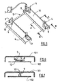
- FIGS. 5 to 7 illustrate the invention in which the upper plate 101 has a profile of generally U-shaped inverted.
- the elements identical to those described above are designated by the same reference numerals.
- the convex surface of the U forms the bearing surface for weighing.
- the lower plate 102 for example flat, is suspended from the upper plate 101 inside the U.
- the lower plate 102 comprises two guide pins 9 (such as screws) which can slide in respective orifices 19 of the upper plate 101.
- the flared upper end of the pin 5 suspends the lower plate 102 to the upper plate 101 (see figure 4 ).
- the U-shaped section of the upper plate 101 stiffens the assembly and forms a volume in which are disposed the measuring members 2, the electrical circuits (cables and others).
- the measuring members 2 can be fixed inside the U on the upper plate 101.
- a lever 12 secured to the measuring member can bear on the bottom plate 102 to measure the mass according to the relative spacing between the plates 101, 102 (see figure 6 ).
- the weighing device according to the invention while being simple and inexpensive structure, allows easy installation and removal of bottles 6.
- the two plates 10, 11 can be placed on the ground spaced around the base of the bottle 6 which is in the vertical position. The operator can then slightly tilt the bottle 6 holding it by the hands in the upper part so as to raise a first side of the base of the bottle 6 relative to the ground.
- the operator can bring a plate 10, 11 of the other plate 11, 10 by inserting it under the raised part of the base of the bottle 6 (the operator carries out this insertion for example with a foot).
- the operator can insert in the same manner the second plate 11, 10 under the other part of the base of the bottle 6.
- the bottle is finally placed in a stable support on the two trays 10, 11 close together. The measurement of mass can begin.
- the figure 3 represents an installation for supplying a fluid to a user U from at least one bottle 6. At least one of the bottles 6 of the installation is weighed by a weighing device as described above.
- the device 3 for restoring data of the weighing device displays 3 or remotely transmits information representative of the filling state of said bottle 6. For example, it triggers an alarm 9 when measuring a determined value.
Landscapes
- Physics & Mathematics (AREA)
- General Physics & Mathematics (AREA)
- Filling Or Discharging Of Gas Storage Vessels (AREA)
Claims (7)
- Wiegevorrichtung für eine Flasche mit einem unter Druck stehenden Fluid, umfassend zwei unterschiedliche Wiegeschalen (10, 11), die selektiv voneinander beabstandet oder einander angenähert werden können, um eine Flasche in stabiler Abstützung rittlings auf den zwei Wiegeschalen (10, 11), die nebeneinander angeordnet sind, platzieren zu können, wobei mindestens eine der zwei Wiegeschalen (10, 11) mindestens ein Organ (2) zum Messen einer physikalischen Größe umfasst, die für die auf die Wiegeschale (10, 11) gestellte Masse repräsentativ ist, wobei die Vorrichtung auch eine Vorrichtung (3) zur Wiedergabe von Daten umfasst, die mit jedem des oder der Messorgane (2) verbunden ist, um eine physikalische Größe, die für die auf den Wiegeschalen (10, 11) angeordnete aktuelle Masse repräsentativ ist, selektiv anzuzeigen und/oder zu übertragen, dadurch gekennzeichnet, dass die äußere Fläche jeder Wiegeschale (10, 11) zwei Ausstülpungen (4) umfasst, die voneinander beabstandet sind, wobei die vier Ausstülpungen (4) der zwei verbundenen Wiegeschalen (10, 11) vier Blockieranschläge bilden, die dazu bestimmt sind, eine auf den Wiegeschalen (10, 11) angeordnete Flasche zwischen den Ausstülpungen (4) zu halten oder zu positionieren, und dass die Ausstülpungen (4) jeder Wiegeschale (10, 11) jeweils in der Nähe von zwei Enden der Wiegeschale (10, 11) angeordnet sind, wobei die vier Ausstülpungen (4) der Vorrichtung die Scheitel eines Vierecks bilden, in dem die Basis der Flasche zwecks ihrer Wiegung abgestellt werden soll, und dass die Messorgane (2) sandwichartig zwischen zwei Platten, einer oberen (101) bzw. einer unteren (102), angeordnet sind, wobei die untere Platte (102) dazu bestimmt ist, auf dem Boden aufzuliegen, wobei die obere Platte (101) eine Abstützfläche für eine Flasche (6) bildet oder mechanisch mit einem Teil (1101) verbunden ist, das eine Abstützfläche für eine Flasche (6) bildet, wobei das Messorgan (2) mit einer der Platten (101, 102) fest verbunden ist und einen Hebel (12) in Abstützung gegen die andere Platte (101, 102) umfasst, um ein Kraftsignal gemäß der relativen Beabstandung der Platten (101, 102) zu übertragen, und dass die obere Platte (101) jeder Wiegeschale (10, 11) eine längliche Form mit einem im Allgemeinen U-förmigen Querschnitt hat, wobei die konvexe Fläche des U die Abstützfläche für eine Flasche (6), in Benutzungsposition, bildet, wobei die zwei Ränder der Platte (101), welche die Füße des U bilden, zum Boden hin ausgerichtet sind, und dass die untere Wiegeschale (102) jeder Platte (10, 11) an der oberen Platte (101) mit der Möglichkeit der relativen Ausfederung zwischen den zwei Platten (101, 102) aufgehängt ist, und dass die obere (101) und die untere (102) Platte jeder Wiegeschale (10, 11) über zwei Führungsstifte (9) in einer Beabstandungs- oder Annäherungsbewegung relativ zu einander in einer Richtung geführt werden, die zu der Ebene der Abstützfläche für eine Flasche senkrecht ist, wobei jede Wiegeschale (10, 11) zwei Führungsstifte (9) umfasst, die mit einer der Platten (101, 102) fest verbunden sind und in einer Öffnung (19) oder einem Sitz gleiten, der mit der anderen Platte (101, 102) fest verbunden ist, wobei die untere Platte über die Führungsstifte (9) an der oberen Platte (101) aufgehängt ist.
- Vorrichtung nach Anspruch 1, dadurch gekennzeichnet, dass sie biegsame oder starre Bänder (5) aufweist, welche die Ausstülpungen (4) ein und derselben Wiegeschale (10, 11) verbinden.
- Vorrichtung nach einem der Ansprüche 1 oder 2, dadurch gekennzeichnet, dass jede Wiegeschale (10, 11) mindestens zwei Organe (2) zum Messen einer physikalischen Größe aufweist, die für die auf die Wiegeschale (10, 11) gestellte Masse repräsentativ ist.
- Vorrichtung nach einem der Ansprüche 1 bis 3, dadurch gekennzeichnet, dass die Organe (2) zum Messen einer physikalischen Größe, die für die auf die Wiegeschale (10, 11) gestellte Masse repräsentativ ist, einen elektronischen Geber wie einer unter den Folgenden umfassen: einen piezoelektrischen Kraftaufnehmer, einen piezoresistiven Dehnungsmessstreifen, einen Zugkraftaufnehmer, einen Druckkraftaufnehmer, einen Biegekraftaufnehmer.
- Vorrichtung nach einem der Ansprüche 1 bis 4, dadurch gekennzeichnet, dass das Volumen des U, das durch die obere Platte (101) gebildet wird, das Messorgan und elektrische Kabel, die mit dem Messorgan (2) verbunden sind, aufnimmt.
- Installation zum Bereitstellen eines Fluids an einen Benutzer (U) aus mindestens einer Flasche (6), wobei die Installation mindestens eine Vorrichtung zum Wiegen einer Flasche (6) der Installation umfasst, dadurch gekennzeichnet, dass die Wiegevorrichtung einem der Ansprüche 1 bis 5 entspricht und dass die Vorrichtung (3) zur Wiedergabe von Daten eine Information überträgt oder anzeigt, die für einen Füllzustand der Flasche (6) repräsentativ ist.
- Verfahren zum Stellen einer Flasche mit einem unter Druck stehenden Fluid auf eine Wiegevorrichtung nach einem der Ansprüche 1 bis 6, dadurch gekennzeichnet, dass es Folgendes umfasst:- einen Schritt des Anordnens der beabstandeten Wiegeschalen (10, 11) um die Basis der Flasche (6) herum,- einen Schritt des Schwenkens der Flasche (6), um eine erste Seite der Basis der Flasche (6) anzuheben,- einen Schritt des Annäherns der Wiegeschalen (10, 11) durch Einbringen einer ersten Wiegeschale (10, 11) unter den angehobenen Teil der Basis der Flasche (6),- einen Schritt des Einbringens einer zweiten Wiegeschale (10, 11) unter den anderen Teil der Basis der Flasche (6), um die Flasche in Abstützung auf den zwei angenäherten Wiegeschalen (10, 11) zu halten.
Applications Claiming Priority (1)
| Application Number | Priority Date | Filing Date | Title |
|---|---|---|---|
| FR1055752A FR2962803B1 (fr) | 2010-07-15 | 2010-07-15 | Dispositif de pesage, installation et procede correspondants |
Publications (2)
| Publication Number | Publication Date |
|---|---|
| EP2407758A1 EP2407758A1 (de) | 2012-01-18 |
| EP2407758B1 true EP2407758B1 (de) | 2013-10-09 |
Family
ID=43536596
Family Applications (1)
| Application Number | Title | Priority Date | Filing Date |
|---|---|---|---|
| EP20110160013 Active EP2407758B1 (de) | 2010-07-15 | 2011-03-28 | Wiegevorrichtung, entsprechende Anlage und entsprechendes Verfahren |
Country Status (2)
| Country | Link |
|---|---|
| EP (1) | EP2407758B1 (de) |
| FR (1) | FR2962803B1 (de) |
Family Cites Families (9)
| Publication number | Priority date | Publication date | Assignee | Title |
|---|---|---|---|---|
| DE1573105A1 (de) * | 1966-10-18 | 1970-10-29 | Michael Schneider | Inhaltsmesser fuer Gasflaschen |
| GB2078982B (en) * | 1980-06-28 | 1985-06-26 | Hearn Geoffrey | Bottle gauge |
| CA1261361A (en) * | 1985-12-19 | 1989-09-26 | Hiroyuki Iida | Foldable weighing scale |
| EP0853235A1 (de) * | 1996-12-21 | 1998-07-15 | Rolf-W. Dr.-Ing. Anschütz | Füllstandsmesseinrichtung für Druckgasflaschen |
| EP1154245A1 (de) * | 2000-05-08 | 2001-11-14 | Merlin Design GmbH | Füllstandsanzeigevorrichtung für Behälter |
| DE10053490A1 (de) * | 2000-10-27 | 2002-05-08 | Goetz Coenen | Vorrichtung zum Bestimmen des Füllstandes eines in einem Behältnis befindlichen insbesondere fluiden Mediums |
| US7234346B2 (en) * | 2003-12-16 | 2007-06-26 | Force Flow | System and method for detecting and displaying an amount of chemical in a cylinder or vessel |
| EP2015036A1 (de) * | 2007-07-09 | 2009-01-14 | Declan Nyhan | Tragbare Waage |
| US7521638B1 (en) * | 2008-02-25 | 2009-04-21 | Travel Caddy, Inc. | Portable scale |
-
2010
- 2010-07-15 FR FR1055752A patent/FR2962803B1/fr not_active Expired - Fee Related
-
2011
- 2011-03-28 EP EP20110160013 patent/EP2407758B1/de active Active
Also Published As
| Publication number | Publication date |
|---|---|
| FR2962803A1 (fr) | 2012-01-20 |
| EP2407758A1 (de) | 2012-01-18 |
| FR2962803B1 (fr) | 2013-07-26 |
Similar Documents
| Publication | Publication Date | Title |
|---|---|---|
| EP2251634B1 (de) | Instrument zur Messung von Abmessungen bestehend aus einer vertikalen Messsäule | |
| US7339123B2 (en) | Electronic scale for measuring weight of person in wheelchair | |
| EP2768757B1 (de) | Lastmanipulator mit verbessertem ausgleich | |
| KR20100023011A (ko) | 저울 기능을 갖는 팔렛트 | |
| EP3870531B1 (de) | Wägesystem für eine arbeitsplattform einer luftseilbahn mit einem mast | |
| CH627843A5 (fr) | Capteur dynamometrique. | |
| WO2018079364A1 (ja) | 荷重検出器、及び荷重検出システム | |
| EP1847798A1 (de) | Instrument zur Messung von Dimensionen und vertikale Säule mit einem solchen Instrument | |
| US20190015015A1 (en) | Load detector and load detecting system | |
| US20050115745A1 (en) | Axle scale technology | |
| EP2407758A1 (de) | Weighing device, corresponding facility and method | |
| EP0987530A1 (de) | Messdose für Druckkräfte | |
| KR20110066655A (ko) | 중량 측정장치 | |
| EP0545832A1 (de) | Steuerknüppel | |
| WO2020084561A1 (fr) | Systeme de pesage pour plate-forme de travail d'une nacelle elevatrice a mat | |
| JP2015206681A (ja) | 体重計 | |
| JP2018091751A (ja) | 荷重検出器及び荷重検出システム | |
| EP3308120B1 (de) | Hochgenaue vorrichtung zur messung von kräften | |
| KR200367996Y1 (ko) | 이동용 축중기와 이에 장착되는 패드 어셈블리. | |
| FR3023693A1 (fr) | Table | |
| FR2711520A1 (fr) | Lit médicalisé modulaire à pesée intégrée. | |
| FR3024979B1 (fr) | Systeme modulaire de chargement pour un monte-personne | |
| FR2690430A1 (fr) | Pèse-charge pour cabine d'ascenseur à plate-forme isolée pneumatiquement. | |
| EP1582849A1 (de) | Kraftaufnehmer und hiermit versehene Wägevorrichtung | |
| EP0123885A1 (de) | Dreidimensionale Längenmesseinrichtung |
Legal Events
| Date | Code | Title | Description |
|---|---|---|---|
| AK | Designated contracting states |
Kind code of ref document: A1 Designated state(s): AL AT BE BG CH CY CZ DE DK EE ES FI FR GB GR HR HU IE IS IT LI LT LU LV MC MK MT NL NO PL PT RO RS SE SI SK SM TR |
|
| AX | Request for extension of the european patent |
Extension state: BA ME |
|
| PUAI | Public reference made under article 153(3) epc to a published international application that has entered the european phase |
Free format text: ORIGINAL CODE: 0009012 |
|
| 17P | Request for examination filed |
Effective date: 20120718 |
|
| 17Q | First examination report despatched |
Effective date: 20120827 |
|
| GRAP | Despatch of communication of intention to grant a patent |
Free format text: ORIGINAL CODE: EPIDOSNIGR1 |
|
| INTG | Intention to grant announced |
Effective date: 20130510 |
|
| GRAS | Grant fee paid |
Free format text: ORIGINAL CODE: EPIDOSNIGR3 |
|
| GRAA | (expected) grant |
Free format text: ORIGINAL CODE: 0009210 |
|
| AK | Designated contracting states |
Kind code of ref document: B1 Designated state(s): AL AT BE BG CH CY CZ DE DK EE ES FI FR GB GR HR HU IE IS IT LI LT LU LV MC MK MT NL NO PL PT RO RS SE SI SK SM TR |
|
| REG | Reference to a national code |
Ref country code: GB Ref legal event code: FG4D Free format text: NOT ENGLISH |
|
| REG | Reference to a national code |
Ref country code: CH Ref legal event code: EP Ref country code: AT Ref legal event code: REF Ref document number: 635755 Country of ref document: AT Kind code of ref document: T Effective date: 20131015 |
|
| REG | Reference to a national code |
Ref country code: IE Ref legal event code: FG4D Free format text: LANGUAGE OF EP DOCUMENT: FRENCH |
|
| REG | Reference to a national code |
Ref country code: DE Ref legal event code: R096 Ref document number: 602011003309 Country of ref document: DE Effective date: 20131205 |
|
| REG | Reference to a national code |
Ref country code: AT Ref legal event code: MK05 Ref document number: 635755 Country of ref document: AT Kind code of ref document: T Effective date: 20131009 |
|
| REG | Reference to a national code |
Ref country code: NL Ref legal event code: VDEP Effective date: 20131009 |
|
| PG25 | Lapsed in a contracting state [announced via postgrant information from national office to epo] |
Ref country code: SI Free format text: LAPSE BECAUSE OF FAILURE TO SUBMIT A TRANSLATION OF THE DESCRIPTION OR TO PAY THE FEE WITHIN THE PRESCRIBED TIME-LIMIT Effective date: 20131009 |
|
| REG | Reference to a national code |
Ref country code: LT Ref legal event code: MG4D |
|
| PG25 | Lapsed in a contracting state [announced via postgrant information from national office to epo] |
Ref country code: SE Free format text: LAPSE BECAUSE OF FAILURE TO SUBMIT A TRANSLATION OF THE DESCRIPTION OR TO PAY THE FEE WITHIN THE PRESCRIBED TIME-LIMIT Effective date: 20131009 Ref country code: HR Free format text: LAPSE BECAUSE OF FAILURE TO SUBMIT A TRANSLATION OF THE DESCRIPTION OR TO PAY THE FEE WITHIN THE PRESCRIBED TIME-LIMIT Effective date: 20131009 Ref country code: LT Free format text: LAPSE BECAUSE OF FAILURE TO SUBMIT A TRANSLATION OF THE DESCRIPTION OR TO PAY THE FEE WITHIN THE PRESCRIBED TIME-LIMIT Effective date: 20131009 Ref country code: IS Free format text: LAPSE BECAUSE OF FAILURE TO SUBMIT A TRANSLATION OF THE DESCRIPTION OR TO PAY THE FEE WITHIN THE PRESCRIBED TIME-LIMIT Effective date: 20140209 Ref country code: NO Free format text: LAPSE BECAUSE OF FAILURE TO SUBMIT A TRANSLATION OF THE DESCRIPTION OR TO PAY THE FEE WITHIN THE PRESCRIBED TIME-LIMIT Effective date: 20140109 Ref country code: NL Free format text: LAPSE BECAUSE OF FAILURE TO SUBMIT A TRANSLATION OF THE DESCRIPTION OR TO PAY THE FEE WITHIN THE PRESCRIBED TIME-LIMIT Effective date: 20131009 Ref country code: FI Free format text: LAPSE BECAUSE OF FAILURE TO SUBMIT A TRANSLATION OF THE DESCRIPTION OR TO PAY THE FEE WITHIN THE PRESCRIBED TIME-LIMIT Effective date: 20131009 |
|
| PG25 | Lapsed in a contracting state [announced via postgrant information from national office to epo] |
Ref country code: ES Free format text: LAPSE BECAUSE OF FAILURE TO SUBMIT A TRANSLATION OF THE DESCRIPTION OR TO PAY THE FEE WITHIN THE PRESCRIBED TIME-LIMIT Effective date: 20131009 Ref country code: PL Free format text: LAPSE BECAUSE OF FAILURE TO SUBMIT A TRANSLATION OF THE DESCRIPTION OR TO PAY THE FEE WITHIN THE PRESCRIBED TIME-LIMIT Effective date: 20131009 Ref country code: AT Free format text: LAPSE BECAUSE OF FAILURE TO SUBMIT A TRANSLATION OF THE DESCRIPTION OR TO PAY THE FEE WITHIN THE PRESCRIBED TIME-LIMIT Effective date: 20131009 Ref country code: RS Free format text: LAPSE BECAUSE OF FAILURE TO SUBMIT A TRANSLATION OF THE DESCRIPTION OR TO PAY THE FEE WITHIN THE PRESCRIBED TIME-LIMIT Effective date: 20131009 Ref country code: LV Free format text: LAPSE BECAUSE OF FAILURE TO SUBMIT A TRANSLATION OF THE DESCRIPTION OR TO PAY THE FEE WITHIN THE PRESCRIBED TIME-LIMIT Effective date: 20131009 Ref country code: CY Free format text: LAPSE BECAUSE OF FAILURE TO SUBMIT A TRANSLATION OF THE DESCRIPTION OR TO PAY THE FEE WITHIN THE PRESCRIBED TIME-LIMIT Effective date: 20131009 |
|
| PG25 | Lapsed in a contracting state [announced via postgrant information from national office to epo] |
Ref country code: PT Free format text: LAPSE BECAUSE OF FAILURE TO SUBMIT A TRANSLATION OF THE DESCRIPTION OR TO PAY THE FEE WITHIN THE PRESCRIBED TIME-LIMIT Effective date: 20140210 |
|
| REG | Reference to a national code |
Ref country code: DE Ref legal event code: R097 Ref document number: 602011003309 Country of ref document: DE |
|
| PG25 | Lapsed in a contracting state [announced via postgrant information from national office to epo] |
Ref country code: EE Free format text: LAPSE BECAUSE OF FAILURE TO SUBMIT A TRANSLATION OF THE DESCRIPTION OR TO PAY THE FEE WITHIN THE PRESCRIBED TIME-LIMIT Effective date: 20131009 |
|
| PLBE | No opposition filed within time limit |
Free format text: ORIGINAL CODE: 0009261 |
|
| STAA | Information on the status of an ep patent application or granted ep patent |
Free format text: STATUS: NO OPPOSITION FILED WITHIN TIME LIMIT |
|
| PG25 | Lapsed in a contracting state [announced via postgrant information from national office to epo] |
Ref country code: SK Free format text: LAPSE BECAUSE OF FAILURE TO SUBMIT A TRANSLATION OF THE DESCRIPTION OR TO PAY THE FEE WITHIN THE PRESCRIBED TIME-LIMIT Effective date: 20131009 Ref country code: CZ Free format text: LAPSE BECAUSE OF FAILURE TO SUBMIT A TRANSLATION OF THE DESCRIPTION OR TO PAY THE FEE WITHIN THE PRESCRIBED TIME-LIMIT Effective date: 20131009 Ref country code: IT Free format text: LAPSE BECAUSE OF FAILURE TO SUBMIT A TRANSLATION OF THE DESCRIPTION OR TO PAY THE FEE WITHIN THE PRESCRIBED TIME-LIMIT Effective date: 20131009 Ref country code: RO Free format text: LAPSE BECAUSE OF FAILURE TO SUBMIT A TRANSLATION OF THE DESCRIPTION OR TO PAY THE FEE WITHIN THE PRESCRIBED TIME-LIMIT Effective date: 20131009 |
|
| 26N | No opposition filed |
Effective date: 20140710 |
|
| PG25 | Lapsed in a contracting state [announced via postgrant information from national office to epo] |
Ref country code: DK Free format text: LAPSE BECAUSE OF FAILURE TO SUBMIT A TRANSLATION OF THE DESCRIPTION OR TO PAY THE FEE WITHIN THE PRESCRIBED TIME-LIMIT Effective date: 20131009 |
|
| REG | Reference to a national code |
Ref country code: DE Ref legal event code: R119 Ref document number: 602011003309 Country of ref document: DE |
|
| REG | Reference to a national code |
Ref country code: DE Ref legal event code: R097 Ref document number: 602011003309 Country of ref document: DE Effective date: 20140710 |
|
| PG25 | Lapsed in a contracting state [announced via postgrant information from national office to epo] |
Ref country code: LU Free format text: LAPSE BECAUSE OF FAILURE TO SUBMIT A TRANSLATION OF THE DESCRIPTION OR TO PAY THE FEE WITHIN THE PRESCRIBED TIME-LIMIT Effective date: 20140328 |
|
| REG | Reference to a national code |
Ref country code: CH Ref legal event code: PL |
|
| REG | Reference to a national code |
Ref country code: IE Ref legal event code: MM4A |
|
| REG | Reference to a national code |
Ref country code: DE Ref legal event code: R119 Ref document number: 602011003309 Country of ref document: DE Effective date: 20141001 |
|
| PG25 | Lapsed in a contracting state [announced via postgrant information from national office to epo] |
Ref country code: DE Free format text: LAPSE BECAUSE OF NON-PAYMENT OF DUE FEES Effective date: 20141001 Ref country code: IE Free format text: LAPSE BECAUSE OF NON-PAYMENT OF DUE FEES Effective date: 20140328 Ref country code: LI Free format text: LAPSE BECAUSE OF NON-PAYMENT OF DUE FEES Effective date: 20140331 Ref country code: CH Free format text: LAPSE BECAUSE OF NON-PAYMENT OF DUE FEES Effective date: 20140331 |
|
| GBPC | Gb: european patent ceased through non-payment of renewal fee |
Effective date: 20150328 |
|
| PG25 | Lapsed in a contracting state [announced via postgrant information from national office to epo] |
Ref country code: GB Free format text: LAPSE BECAUSE OF NON-PAYMENT OF DUE FEES Effective date: 20150328 |
|
| PG25 | Lapsed in a contracting state [announced via postgrant information from national office to epo] |
Ref country code: MT Free format text: LAPSE BECAUSE OF FAILURE TO SUBMIT A TRANSLATION OF THE DESCRIPTION OR TO PAY THE FEE WITHIN THE PRESCRIBED TIME-LIMIT Effective date: 20131009 |
|
| REG | Reference to a national code |
Ref country code: FR Ref legal event code: PLFP Year of fee payment: 6 |
|
| PG25 | Lapsed in a contracting state [announced via postgrant information from national office to epo] |
Ref country code: SM Free format text: LAPSE BECAUSE OF FAILURE TO SUBMIT A TRANSLATION OF THE DESCRIPTION OR TO PAY THE FEE WITHIN THE PRESCRIBED TIME-LIMIT Effective date: 20131009 |
|
| PG25 | Lapsed in a contracting state [announced via postgrant information from national office to epo] |
Ref country code: MC Free format text: LAPSE BECAUSE OF FAILURE TO SUBMIT A TRANSLATION OF THE DESCRIPTION OR TO PAY THE FEE WITHIN THE PRESCRIBED TIME-LIMIT Effective date: 20131009 |
|
| PG25 | Lapsed in a contracting state [announced via postgrant information from national office to epo] |
Ref country code: GR Free format text: LAPSE BECAUSE OF FAILURE TO SUBMIT A TRANSLATION OF THE DESCRIPTION OR TO PAY THE FEE WITHIN THE PRESCRIBED TIME-LIMIT Effective date: 20140110 Ref country code: BG Free format text: LAPSE BECAUSE OF FAILURE TO SUBMIT A TRANSLATION OF THE DESCRIPTION OR TO PAY THE FEE WITHIN THE PRESCRIBED TIME-LIMIT Effective date: 20131009 |
|
| PG25 | Lapsed in a contracting state [announced via postgrant information from national office to epo] |
Ref country code: HU Free format text: LAPSE BECAUSE OF FAILURE TO SUBMIT A TRANSLATION OF THE DESCRIPTION OR TO PAY THE FEE WITHIN THE PRESCRIBED TIME-LIMIT; INVALID AB INITIO Effective date: 20110328 Ref country code: TR Free format text: LAPSE BECAUSE OF FAILURE TO SUBMIT A TRANSLATION OF THE DESCRIPTION OR TO PAY THE FEE WITHIN THE PRESCRIBED TIME-LIMIT Effective date: 20131009 Ref country code: BE Free format text: LAPSE BECAUSE OF FAILURE TO SUBMIT A TRANSLATION OF THE DESCRIPTION OR TO PAY THE FEE WITHIN THE PRESCRIBED TIME-LIMIT Effective date: 20140331 |
|
| REG | Reference to a national code |
Ref country code: FR Ref legal event code: PLFP Year of fee payment: 7 |
|
| REG | Reference to a national code |
Ref country code: FR Ref legal event code: PLFP Year of fee payment: 8 |
|
| PG25 | Lapsed in a contracting state [announced via postgrant information from national office to epo] |
Ref country code: MK Free format text: LAPSE BECAUSE OF FAILURE TO SUBMIT A TRANSLATION OF THE DESCRIPTION OR TO PAY THE FEE WITHIN THE PRESCRIBED TIME-LIMIT Effective date: 20131009 |
|
| PG25 | Lapsed in a contracting state [announced via postgrant information from national office to epo] |
Ref country code: AL Free format text: LAPSE BECAUSE OF FAILURE TO SUBMIT A TRANSLATION OF THE DESCRIPTION OR TO PAY THE FEE WITHIN THE PRESCRIBED TIME-LIMIT Effective date: 20131009 |
|
| PGFP | Annual fee paid to national office [announced via postgrant information from national office to epo] |
Ref country code: FR Payment date: 20260320 Year of fee payment: 16 |