EP2407620A1 - Profiled upright for supporting a device which retains a pivoting door leaf by attraction and attraction supporting device including said upright - Google Patents
Profiled upright for supporting a device which retains a pivoting door leaf by attraction and attraction supporting device including said upright Download PDFInfo
- Publication number
- EP2407620A1 EP2407620A1 EP11305866A EP11305866A EP2407620A1 EP 2407620 A1 EP2407620 A1 EP 2407620A1 EP 11305866 A EP11305866 A EP 11305866A EP 11305866 A EP11305866 A EP 11305866A EP 2407620 A1 EP2407620 A1 EP 2407620A1
- Authority
- EP
- European Patent Office
- Prior art keywords
- complementary
- profiled
- base
- main
- attraction
- Prior art date
- Legal status (The legal status is an assumption and is not a legal conclusion. Google has not performed a legal analysis and makes no representation as to the accuracy of the status listed.)
- Granted
Links
- 230000000295 complement effect Effects 0.000 claims abstract description 75
- 239000003302 ferromagnetic material Substances 0.000 claims abstract description 7
- 230000000903 blocking effect Effects 0.000 claims description 4
- 210000002105 tongue Anatomy 0.000 description 13
- 101001017827 Mus musculus Leucine-rich repeat flightless-interacting protein 1 Proteins 0.000 description 3
- 230000001154 acute effect Effects 0.000 description 2
- 230000014759 maintenance of location Effects 0.000 description 2
- 238000010079 rubber tapping Methods 0.000 description 2
- XAGFODPZIPBFFR-UHFFFAOYSA-N aluminium Chemical compound [Al] XAGFODPZIPBFFR-UHFFFAOYSA-N 0.000 description 1
- 229910052782 aluminium Inorganic materials 0.000 description 1
- 230000005489 elastic deformation Effects 0.000 description 1
- 238000012423 maintenance Methods 0.000 description 1
- 238000004519 manufacturing process Methods 0.000 description 1
- 239000000463 material Substances 0.000 description 1
- 238000012986 modification Methods 0.000 description 1
- 230000004048 modification Effects 0.000 description 1
- 239000011120 plywood Substances 0.000 description 1
- 238000011084 recovery Methods 0.000 description 1
- 230000002441 reversible effect Effects 0.000 description 1
- 239000007787 solid Substances 0.000 description 1
- 238000006467 substitution reaction Methods 0.000 description 1
Images


Classifications
-
- E—FIXED CONSTRUCTIONS
- E05—LOCKS; KEYS; WINDOW OR DOOR FITTINGS; SAFES
- E05C—BOLTS OR FASTENING DEVICES FOR WINGS, SPECIALLY FOR DOORS OR WINDOWS
- E05C19/00—Other devices specially designed for securing wings, e.g. with suction cups
- E05C19/16—Devices holding the wing by magnetic or electromagnetic attraction
- E05C19/166—Devices holding the wing by magnetic or electromagnetic attraction electromagnetic
-
- E—FIXED CONSTRUCTIONS
- E05—LOCKS; KEYS; WINDOW OR DOOR FITTINGS; SAFES
- E05B—LOCKS; ACCESSORIES THEREFOR; HANDCUFFS
- E05B17/00—Accessories in connection with locks
- E05B17/0004—Lock assembling or manufacturing
- E05B17/0008—Lock parts made by extrusion process
-
- E—FIXED CONSTRUCTIONS
- E05—LOCKS; KEYS; WINDOW OR DOOR FITTINGS; SAFES
- E05B—LOCKS; ACCESSORIES THEREFOR; HANDCUFFS
- E05B1/00—Knobs or handles for wings; Knobs, handles, or press buttons for locks or latches on wings
- E05B1/0015—Knobs or handles which do not operate the bolt or lock, e.g. non-movable; Mounting thereof
Definitions
- the present invention relates to the field of devices for holding the swinging door leaves in the closed position in respective dormant frames by attraction, more particularly electromagnetic, and relates to a profiled upright intended to equip such a holding device and to be fixed on a pivoting leaf body for supporting a holding part by attraction, more particularly electromagnetic. It also relates to such a device for holding a door leaf by attraction, more particularly electromagnetic, equipped with said profiled upright.
- a pivotal door leaf generally has a rectangular shape with two opposite and parallel lateral sides which extend vertically, in the mounted state of said leaf in the door, and of which one of said opposite sides is intended to be pivotally mounted. on a door frame or fixed frame engaged in a bay, while the other opposite lateral side, or free lateral side, is intended to bear against the rebate bottom of the frame, in the closed position of the leaf.
- holding devices which are specially designed to maintain a pivoting leaf in the closed position of the door in a dormant frame by attraction, generally electromagnetic, two holding parts between them by attraction, respectively integral with the leaf and the sleeping frame, one with respect to the other.
- Such a holding device generally comprises, on the one hand, a support profile intended to be fixed on the frame and being able to support a first attraction-holding part, of the electromagnet type, respectively of the type of counterplate made of ferromagnetic material, and a profiled upright intended to be fixed on the leaf and to receive a second holding part by attraction, the type of plywood of ferromagnetic material, respectively of the electromagnet type.
- the two retention portions by attraction are able to cooperate with each other, in the closing state of the leaf, so that the first holding part exerts a force, more particularly electromagnetic force, on the second holding part for blocking said leaf in the closed position.
- the profiled amount is generally fixed on the face of the body of the wing which is visible, in the closed position of the latter, for an observer located in the deflection zone of the wing. It is more particularly fixed on the body of the flap along and near the free lateral side of the latter, so that the portion of the profiled post supporting one of the holding parts is located outside and beyond the free lateral side of the wing.
- an attraction-holding part may be constituted by one or more attraction-holding parts, each, for example, of the electromagnet or counterplate type of ferromagnetic material or the like.
- the profiled support and the profiled upright, forming an assembly usually referred to as a band, of such a holding device are generally each in the form of a tubular section comprising at least one holding part aperture adapted to receive a holding part by attraction.
- the integral profiled amount of the leaf generally comprises a gripping means forming a door handle and usually consisting of a lateral extension of the apparent face of the profiled post opposite the face having at least one holding portion opening.
- the object of the present invention is to overcome these drawbacks by proposing a shaped upright intended to equip a device for holding a pivoting door leaf by attraction, more particularly an electromagnetic attraction, making it possible to adapt to a specific type of leaf, such as a leaf having a rebate, and / or possibly a type specific frame, such as a frame with a main rebate and a complementary rebate receiving support recovery from the rabbet formed in the edge of the free side of the leaf.
- the present invention relates to a profiled upright intended to equip a device for holding a pivoting door leaf by attraction, more particularly electromagnetic, in the closed position in a frame, said profiled upright, which is intended to to be fixed to the body of said leaf and to support an attraction-retaining portion, of the electromagnet or counterplate type of ferromagnetic material or the like, comprising a main section comprising a base provided with a bearing surface and main fixing allowing the fixing said profiled upright on the body of the leaf and, optionally, gripping means forming a door handle, and essentially characterized in that it further comprises a complementary profile provided with a bearing and fixing surface complementary, capable of being assembled rigidly, removably, with said base, so as to extend and out laterally, thanks to said support surface and complementary attachment, the bearing surface and main attachment of said base.
- the present invention also relates to a device for holding a pivoting door leaf, by attraction, more particularly electromagnetic, said leaf, characterized in that it comprises essentially, firstly, a profiled amount as defined according to the present invention and intended to be fixed on the body of said leaf and to support a first retaining part by attraction of the counterplate type, respectively of the electromagnet type, and, secondly, a profiled support intended to be fixed on the frame of the door and to support a second holding portion of the electromagnet type, respectively of the counterplate type, capable of cooperating with said first holding portion, in the closing state of the leaf in the frame, so that one of said first and second holding parts exerts an electromagnetic force on the other for locking said leaf in the closed position.
- the figures show a profiled upright intended to equip a device for holding a swing door 1 by attraction, more particularly electromagnetic, in the closed position in a fixed frame 2, said profiled upright, which is intended to be fixed on the body of said wing 1 and to support a holding portion 3 or 4 by attraction, more particularly electromagnetic, electromagnet type 3 or against plate 4 of ferromagnetic material or other similar material, comprising a main section 5 having a base 5 'provided with a main support and fixing surface 6 for attaching said profiled post to an appropriate area of the body of the wing 1 and, optionally, gripping means 7 forming a door handle.
- such a profiled upright further comprises a complementary profile 8, which has a complementary support and fixing surface 9, and which is capable of being rigidly assembled, removably, with the base 5 ', so as to extend and extend laterally, through said bearing surface and complementary attachment 9, the bearing surface and main attachment 6 of the base 5'.
- a profiled upright can be fixed on the body of a wing 1 of pivoting door, near the free lateral side of the wing 1 opposite to that, not shown, pivotally mounted on the frame 2, so as to allow cooperation, in the state of closure of the wing 1, between the two holding portions 3 and 4 by attraction.
- a holding portion 3, respectively 4 can be covered, with its profiled support 19 secured to the fixed frame 2, by the main section 5 which has a receiving opening provided for this purpose, coming s' apply against the other holding part 4, respectively 3, housed in the main section 5.
- flap 1 In the case of a specific type of flap 1, such as a flap 1 ', it does not allow, as can be seen on the figure 1 , fix the base 5 'of the profiled upright on the body of the wing 1 at the rabbet 1', which is formed in the free lateral side of the latter and thus to position the holding portion 4, respectively 3, housed in said profiled post so as to make it cooperate by attraction with the holding part 3, respectively 4, housed in the profiled support 19 secured to the fixed frame 2.
- the rabbet 1 ' which is cut in the edge of the free lateral side of the wing 1, leaves at said side a thin covering portion from covering the corresponding part of the outer face of the frame and not allowing to fix the profiled upright in said zone.
- the profiled support integral with the fixed frame 2 can not be shifted sufficiently towards the free lateral edge of the leaf 1 because of the said overlap area which is engaged in a complementary rabbet 2 "of a main rabbet 2 'formed in the dormant frame 2, allowing flush with the frame 2 and the flap 1.
- the complementary profile 8 allows, thanks to the bearing surface and complementary attachment 9, to fix the latter further on the body of the wing 1, in other words more recessed from the free lateral edge and the rabbet 1 of the wing 1, in an area to ensure a resistance and a distribution of the effective mechanical fixing effort, while maintaining, in the closed position of the latter, the spacing between the integral profiled upright of the wing 1 and the shaped support integral with the fixed frame 2, which ensures the functional cooperation of maintaining by attraction between the holding portions 3 and 4 respectively, in order to block the wing 1 in the closed position in the fixed frame 2 of the door.
- the complementary profile 8 may comprise essentially an interlocking portion 8 'and a surface extension portion 8 "integrating the complementary bearing and fixing surface 9.
- the part 8 'and the base 5' can be adapted to be fitted and assembled one into the other, while removable locking means 10 can ensure the locking in the assembled state of the complementary section 8 with the 5 'base ( Figures 1 to 3 ).
- the removable locking means 10 may consist of at least one pressure screw adapted to pass through the bottom of the U-shaped interlocking portion 8 'of the complementary profile 8 to exert pressure on the bottom of the base 5 in order to prevent longitudinal sliding or sliding by adhesion of said complementary section 8 fitted by its interlocking portion 8 'into said base 5' ( figure 1 ).
- the support surface and complementary fastening 9 extends laterally, substantially in the same plane, the bearing surface and main attachment 6 of the base 5 '.
- the interlocking portion 8 'and the base 5' can be nested one inside the other by longitudinal sliding, thanks to a set of grooves 11, 12 and ribs 13, 14. These can be made longitudinally respectively in the base 5 'and in the interlocking portion 8' of the complementary profile 8, over all or part of their length, continuously or not ( figure 1 and figure 3 ).
- Such sliding engagement makes it possible to ensure effective mechanical rigidity of the connection between the complementary profile 8 and the main profile 5.
- interlocking assembly such as, for example, a reversible male / female elastic assembly also known by the usual name of snap-fastening, clipping or elastic locking.
- the main bearing and fixing surface 6 can advantageously end with a main tongue 13, extending on the opposite side to said bearing surface and forming a rib, able to be fitted by sliding into a groove. sliding and longitudinal interlocking space 12, forming a groove, longitudinally separating the interlocking portion 8 'of the surface extension portion 8 "of the complementary section 8 ( figure 1 and figure 3 ).
- a main tongue 13 may extend substantially perpendicular to the main support and fixing surface 6, or with an inclination with respect to a plane perpendicular to said surface, preferably with an inclination which is oriented towards the main section 5, in the assembly state ( figure 1 ), that is to say forming an acute angle with the inner face of the surface extension portion 8 "opposite to the outer face forming the main bearing and fixing surface 6.
- the base 5 ' it can be profiled so as to have a generally U-shaped cross section, the bottom of which said base 5' integrates the support surface and main attachment 6, one of the lateral wings of said base 5 'can then be constituted by the main tongue 13.
- the complementary profile 8 may comprise two longitudinally contiguous parts, one of which is profiled so as to have a generally U-shaped cross section, may constitute the interlocking portion 8 'of the complementary section 8, while that the other part, of generally L-shaped or U-shaped cross section, can constitute the surface extension portion 8 "of the latter ( figure 4 ).
- interlocking portion 8 'and the extension portion 8 " are interconnected by the longitudinal free end edge of one of their lateral flanges, and it can be seen that the junction between the two edges longitudinal free end end may advantageously extend laterally on either side of said junction into the interlocking portion 8 and in the extension portion 8 ", so as to create two longitudinal free end edges 18 delimiting each, with the free end edge longitudinal 18 of the lateral wing opposite to that forming the junction, the longitudinal opening of the corresponding interlocking portion 8 'or extension 8 ".
- the complementary support and fixing surface 9 can extend laterally in the sliding space and longitudinal interlocking 12 by a longitudinal flange 18 'adapted to engage in a complementary cutout 18 "( figure 4 ) made in the lower free end edge of the base 5 ', under the main tongue 13, so as to further strengthen the connection of the assembly between the base 5' and the complementary profile 8 and in particular the blocking performed by the pressure screws 10.
- main section 5 it may consist of a tubular section comprising at least one holding portion receiving opening 3 or 4, one of the lateral sides of the main tubular section extends laterally outwardly by the bearing surface and main attachment 6 of the base 5 '.
- one of the lateral flanges of said U-shaped base 5 ', opposite that constituting the main tongue 13, can be integrated into the corresponding lateral side of said main tubular section ( figures 1 , 2 and 4 ).
- the inner face of the side flange of the base 5 ', opposite that forming the main tongue 13, may comprise at least one longitudinal rib 14 adapted to be fitted by sliding in a groove 11 formed in the outer face of one of the lateral flanges of the U-shaped interlocking portion 8 'of the complementary profile 8.
- Said internal face may, in a variant not shown in the appended figures, comprise at least one spline adapted to receive, by sliding engagement longitudinal, a rib made longitudinally in the external face of one of the lateral wings of the U-shaped interlocking portion 8 'of the complementary section 8.
- bearing and main fixing surfaces 6 and complementary 9 may each be able to be fixed on the body of the wing 1 by means of rigid and removable connection means 15, such as assembly screws, securing said pressure fastening of said main bearing and fixing surface 6 ( figure 2 ) and complementary 9 ( figure 1 ) against the corresponding face of the body of the wing 1.
- the present invention may further provide that the surface extension portion 8 "advantageously terminates in a complementary tongue 16, preferably extending, in the interlocking state, substantially parallel to the main tongue 13 so said surface extension portion 8 "has a generally U-shaped cross section.
- the respective longitudinal openings of the U-shaped interlocking portion 8 'and the U-shaped surface extension portion 8 can each be closed by a removable cover 17 having two edges.
- the opening of the U-shaped base 5 ' is also able to be closed by such a removable cover 17.
- Such attachment sites may each preferably consist of one of the longitudinal free end edges 18 of the interlocking portion 8 'or the extension portion 8 ", respectively.
- these removable covers 17 may each have a substantially rectangular shape. More particularly, a removable cover 17 may preferably be fastened to two adjacent longitudinal free end edges 18 delimiting the longitudinal opening of an interlocking portion 8 'or a U-shaped extension 8, respectively. cover 17 may be slightly curved with respect to its longitudinal axis, so as to promote its connection by elastic deformation about said axis and to adapt each removable cover 17 to the spacing of the corresponding opening to close.
- the present invention may advantageously provide that all the removable covers 17 are identical and that, likewise, the openings adapted to receive them, delimited by the longitudinal free end edges 18 of the interlocking portions 8 'and 8' respectively. corresponding "extension 8" are also identical, so as to standardize the manufacture and use of said covers.
- the present invention can advantageously provide that positioning grooves 20, shallow, playing a role of positioning marking, are practiced in the respective bottoms of the base 5 'of the main section 5 and the interlocking portion' 8 'of the complementary section 8, to allow a quick positioning of the set screws 10 and the assembly screws 15 or the like.
- the complementary profile may comprise an assembly portion and a surface extension portion incorporating the complementary bearing and fixing surface 9 and said assembly part can be adapted to be fixed on the base 5 'by rigid and removable connecting means ensuring the attachment by pressure of at least one contact surface of said assembly part against a corresponding contact surface of the base 5 '.
- the complementary support and fixing surface 9 may end with a tongue similar to the complementary tongue 16 described above for securing a lid.
- removable 17 between said tongue and the main section 5 so as to ensure the finishing and to hide the rigid and removable connecting means ensuring the assembly of the complementary profile with said main section 5.
- Such a removable cover may have edges latching side 17 'allowing its attachment to the attachment sites of the complementary section 8 and the main section 5 such as the longitudinal edge of the complementary tongue 16 and a fastening rib 14 fixed for example on the outer side of the lateral side of the main section 5.
- the present invention may further advantageously provide that an end cap 21 is adapted to be removably attached to each free end, upper or lower, of the profiled upright according to the present invention, together with the complementary profile 8, in order to ensure the finish and strengthen the strength of the assembly of the latter with the profiled amount.
- Such an end cap may preferably be made of aluminum and be fastened to the corresponding upper or lower free end of the profiled upright by means of connecting means 22 'such as, for example, trilobal self-tapping screws or other screwing means, in particular self-tapping or self-forming, to strengthen the assembly between the main profile of the profile upright and the complementary profile.
- screw drums 22 may be provided in the main section 5 and in the complementary section 8 to receive said connecting means 22 '.
- their lateral wings and, if appropriate, their tongues may advantageously form an acute angle with their respective funds.
- the main tubular section may comprise an extension 7, forming a gripping means for opening the door, extending laterally from one of its lateral sides, in particular at its apparent face, to the mounted state, opposite to that having at least one retention portion opening by attraction and can advantageously further comprise a recess 23 formed in the lateral side opposite to that comprising said extension 7 and completing the latter as a gripping means to further improve the seizure of the main section 5 and more particularly to allow ambidextrous gripping.
- a holding part aperture is adapted to receive at least one attraction holding piece such as an electromagnet or electromagnetic pad or a counterplate.
- the present invention also relates to a device for holding a swing door 1, by attraction, more particularly electromagnetic, of said wing 1, comprising, on the one hand, a profiled upright as defined according to the present invention and intended to be fixed on the body of said leaf 1 and to support a first holding part 4 by attraction of the counterplate type, respectively of the electromagnet type, and, secondly, a profiled support 19 intended to be fixed on the frame 2 of the door and to support a second holding part 3 by attraction of the electromagnet type, respectively of the counterplate type, capable of cooperating with said first holding portion 4, in the closed state of the leaf 1 in the frame 2, so that one of said first and second holding portions 3 and 4 exerts an electromagnetic force on the other to block said leaf 1 in the closed position ure.
Landscapes
- Engineering & Computer Science (AREA)
- Physics & Mathematics (AREA)
- Electromagnetism (AREA)
- Manufacturing & Machinery (AREA)
- Mechanical Engineering (AREA)
- Wing Frames And Configurations (AREA)
Abstract
Description
La présente invention concerne le domaine des dispositifs de maintien des battants de porte pivotants en position de fermeture dans des cadres dormants respectifs par attraction, plus particulièrement électromagnétique, et a pour objet un montant profilé destiné à équiper un tel dispositif de maintien et à être fixé sur un corps de battant pivotant en vue de supporter une partie de maintien par attraction, plus particulièrement électromagnétique. Elle a également pour objet un tel dispositif de maintien d'un battant de porte par attraction, plus particulièrement électromagnétique, équipé dudit montant profilé.The present invention relates to the field of devices for holding the swinging door leaves in the closed position in respective dormant frames by attraction, more particularly electromagnetic, and relates to a profiled upright intended to equip such a holding device and to be fixed on a pivoting leaf body for supporting a holding part by attraction, more particularly electromagnetic. It also relates to such a device for holding a door leaf by attraction, more particularly electromagnetic, equipped with said profiled upright.
Un battant de porte pivotant présente généralement une forme rectangulaire avec deux côtés latéraux opposés et parallèles entre eux qui s'étendent verticalement, à l'état monté dudit battant dans la porte, et dont l'un desdits côtés opposés est destiné à être monté pivotant sur un châssis de porte ou cadre dormant engagé dans une baie, tandis que l'autre côté latéral opposé, ou côté latéral libre, est destiné à venir en appui contre le fond de feuillure du cadre dormant, en position de fermeture du battant.A pivotal door leaf generally has a rectangular shape with two opposite and parallel lateral sides which extend vertically, in the mounted state of said leaf in the door, and of which one of said opposite sides is intended to be pivotally mounted. on a door frame or fixed frame engaged in a bay, while the other opposite lateral side, or free lateral side, is intended to bear against the rebate bottom of the frame, in the closed position of the leaf.
Par ailleurs, on connaît déjà des dispositifs de maintien qui sont spécialement conçus pour maintenir un battant pivotant en position de fermeture de la porte dans un cadre dormant par attraction, généralement électromagnétique, de deux parties de maintien entre elles par attraction, respectivement solidaire du battant et du dormant, l'une par rapport à l'autre.Furthermore, there are already known holding devices which are specially designed to maintain a pivoting leaf in the closed position of the door in a dormant frame by attraction, generally electromagnetic, two holding parts between them by attraction, respectively integral with the leaf and the sleeping frame, one with respect to the other.
Un tel dispositif de maintien comprend généralement, d'une part, un profilé support destiné à être fixé sur le dormant et étant apte à supporter une première partie de maintien par attraction, du type électroaimant, respectivement du type contreplaque en matériau ferromagnétique, et un montant profilé destiné à être fixé sur le battant et à recevoir une deuxième partie de maintien par attraction, du type contreplaque en matériau ferromagnétique, respectivement du type électroaimant. Les deux parties de maintien par attraction sont susceptibles de coopérer entre elles, à l'état de fermeture du battant, de sorte que la première partie de maintien exerce une force, plus particulièrement électromagnétique, sur la deuxième partie de maintien permettant de bloquer ledit battant en position de fermeture.Such a holding device generally comprises, on the one hand, a support profile intended to be fixed on the frame and being able to support a first attraction-holding part, of the electromagnet type, respectively of the type of counterplate made of ferromagnetic material, and a profiled upright intended to be fixed on the leaf and to receive a second holding part by attraction, the type of plywood of ferromagnetic material, respectively of the electromagnet type. The two retention portions by attraction are able to cooperate with each other, in the closing state of the leaf, so that the first holding part exerts a force, more particularly electromagnetic force, on the second holding part for blocking said leaf in the closed position.
Le montant profilé est généralement fixé sur la face du corps du battant qui est visible, en situation de fermeture de ce dernier, pour un observateur situé dans la zone de débattement du battant. Il est plus particulièrement fixé sur le corps du battant le long et à proximité du côté latéral libre de ce dernier, de sorte que la portion du montant profilé supportant l'une des parties de maintien est située à l'extérieur et au-delà du côté latéral libre du battant.The profiled amount is generally fixed on the face of the body of the wing which is visible, in the closed position of the latter, for an observer located in the deflection zone of the wing. It is more particularly fixed on the body of the flap along and near the free lateral side of the latter, so that the portion of the profiled post supporting one of the holding parts is located outside and beyond the free lateral side of the wing.
On notera qu'une partie de maintien par attraction peut être constituée par une ou plusieurs pièces de maintien par attraction, chacune, par exemple, du type électroaimant ou contreplaque en matériau ferromagnétique ou analogue.It will be noted that an attraction-holding part may be constituted by one or more attraction-holding parts, each, for example, of the electromagnet or counterplate type of ferromagnetic material or the like.
Le support profilé et le montant profilé, formant un ensemble usuellement dénommé bandeau, d'un tel dispositif de maintien se présentent généralement chacun sous la forme d'un profilé tubulaire comportant au moins une ouverture de partie de maintien apte à recevoir une pièce de maintien par attraction.The profiled support and the profiled upright, forming an assembly usually referred to as a band, of such a holding device are generally each in the form of a tubular section comprising at least one holding part aperture adapted to receive a holding part by attraction.
En outre, le montant profilé solidaire du battant comporte généralement un moyen de préhension formant une poignée de porte et consistant, habituellement, en un prolongement latéral de la face apparente du montant profilé opposée à la face comportant au moins une ouverture de partie de maintien.In addition, the integral profiled amount of the leaf generally comprises a gripping means forming a door handle and usually consisting of a lateral extension of the apparent face of the profiled post opposite the face having at least one holding portion opening.
Toutefois, un problème se pose lorsque le type de battant ne permet pas de respecter l'écartement, à l'état de fermeture du battant, entre le support profilé solidaire du dormant et le montant profilé solidaire du battant, pour permettre d'assurer la coopération entre les deux parties de maintien par attraction. Ceci est, par exemple, le cas, lorsqu'un type de battant comporte une feuillure, pratiquée dans le chant de son côté latéral libre, créant un recouvrement de faible épaisseur, destiné à recouvrir la partie correspondante de la face externe du dormant, insuffisante pour permettre une fixation solide du montant profilé et qu'il est impossible de compenser ce décalage dû à la feuillure du battant par un décalage du support profilé solidaire du dormant vers le battant.However, a problem arises when the type of leaf does not allow to respect the spacing, in the state of closing of the leaf, between the support integral section of the frame and the profiled integral piece of the leaf, to allow to ensure the cooperation between the two parts of maintenance by attraction. This is, for example, the case when a type of leaf has a rabbet, made in the edge of its free lateral side, creating a thin covering, intended to cover the corresponding part of the outer face of the frame, insufficient to allow a solid attachment of the profiled upright and it is impossible to compensate for this shift due to the rabbet of the leaf by a shift of the shaped support integral with the frame to the leaf.
La présente invention a pour but de pallier ces inconvénients en proposant un montant profilé destiné à équiper un dispositif de maintien d'un battant de porte pivotant par attraction, plus particulièrement électromagnétique, permettant de s'adapter à un type de battant spécifique, tel qu'un battant comportant une feuillure, et/ou, éventuellement, à un type de cadre dormant spécifique, tel qu'un cadre dormant comportant une feuillure principale et une feuillure complémentaire recevant en appui le recouvrement issu de la feuillure pratiquée dans le chant du côté libre du battant.The object of the present invention is to overcome these drawbacks by proposing a shaped upright intended to equip a device for holding a pivoting door leaf by attraction, more particularly an electromagnetic attraction, making it possible to adapt to a specific type of leaf, such as a leaf having a rebate, and / or possibly a type specific frame, such as a frame with a main rebate and a complementary rebate receiving support recovery from the rabbet formed in the edge of the free side of the leaf.
A cet effet, la présente invention a pour objet un montant profilé destiné à équiper un dispositif de maintien d'un battant de porte pivotant par attraction, plus particulièrement électromagnétique, en position de fermeture dans un cadre dormant, ledit montant profilé, qui est destiné à être fixé sur le corps dudit battant et à supporter une partie de maintien par attraction, du type électroaimant ou contreplaque en matériau ferromagnétique ou analogue, comprenant un profilé principal comportant une embase munie d'une surface d'appui et de fixation principale permettant la fixation dudit montant profilé sur le corps du battant et, éventuellement, des moyens de préhension formant poignée de porte, et se caractérisant essentiellement en ce qu'il comprend, en outre, un profilé complémentaire muni d'une surface d'appui et de fixation complémentaire, susceptible d'être assemblé rigidement, de manière amovible, avec ladite embase, de sorte à prolonger et à étendre latéralement, grâce à ladite surface d'appui et de fixation complémentaire, la surface d'appui et de fixation principale de ladite embase.For this purpose, the present invention relates to a profiled upright intended to equip a device for holding a pivoting door leaf by attraction, more particularly electromagnetic, in the closed position in a frame, said profiled upright, which is intended to to be fixed to the body of said leaf and to support an attraction-retaining portion, of the electromagnet or counterplate type of ferromagnetic material or the like, comprising a main section comprising a base provided with a bearing surface and main fixing allowing the fixing said profiled upright on the body of the leaf and, optionally, gripping means forming a door handle, and essentially characterized in that it further comprises a complementary profile provided with a bearing and fixing surface complementary, capable of being assembled rigidly, removably, with said base, so as to extend and out laterally, thanks to said support surface and complementary attachment, the bearing surface and main attachment of said base.
La présente invention a également pour objet un dispositif de maintien d'un battant de porte pivotant, par attraction, plus particulièrement électromagnétique, dudit battant, caractérisée en ce qu'il comprend essentiellement, d'une part, un montant profilé tel que défini selon la présente invention et destiné à être fixé sur le corps dudit battant et à supporter une première partie de maintien par attraction du type contreplaque, respectivement du type électroaimant, et, d'autre part, un support profilé destiné à être fixé sur le cadre dormant de la porte et à supporter une deuxième partie de maintien du type électroaimant, respectivement du type contreplaque, susceptible de coopérer avec ladite première partie de maintien, à l'état de fermeture du battant dans le cadre dormant, de sorte que l'une desdites première et deuxième parties de maintien exerce une force électromagnétique sur l'autre permettant de bloquer ledit battant en position de fermeture.The present invention also relates to a device for holding a pivoting door leaf, by attraction, more particularly electromagnetic, said leaf, characterized in that it comprises essentially, firstly, a profiled amount as defined according to the present invention and intended to be fixed on the body of said leaf and to support a first retaining part by attraction of the counterplate type, respectively of the electromagnet type, and, secondly, a profiled support intended to be fixed on the frame of the door and to support a second holding portion of the electromagnet type, respectively of the counterplate type, capable of cooperating with said first holding portion, in the closing state of the leaf in the frame, so that one of said first and second holding parts exerts an electromagnetic force on the other for locking said leaf in the closed position.
L'invention sera mieux comprise, grâce à la description ci-après, qui se rapporte à un mode de réalisation préféré, donné à titre d'exemple non limitatif, et expliqué avec référence aux dessins schématiques annexés, dans lesquels :
- la
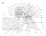
figure 1 représente une vue en coupe transversale du profilé principal d'un montant profilé selon la présente invention, avec profilé complémentaire, équipant un dispositif de maintien d'un battant de porte pivotant avec feuillure, par attraction électromagnétique, à l'état monté dans une porte et en position de fermeture dudit battant dans un cadre dormant, - la
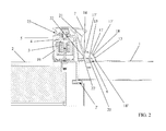
figure 2 représente une vue en coupe transversale du profilé principal d'un montant profilé, selon la présente invention, sans profilé complémentaire, équipant un dispositif de maintien d'un battant de porte pivotant sans feuillure, par attraction électromagnétique, à l'état monté et en position de fermeture dudit battant dans un cadre dormant, - la
figure 3 représente une vue de profil du profilé complémentaire selon la présente invention, - la
figure 4 représente une vue de profil du profilé principal du montant profilé selon la présente invention.
- the
figure 1 represents a cross-sectional view of the main profile of a profiled upright according to the present invention, with complementary profile, equipping a device for holding a revolving door flap with rebate, by electromagnetic attraction, in the mounted state in a door and in the closed position of said leaf in a dormant frame, - the
figure 2 represents a cross-sectional view of the main profile of a profiled upright, according to the present invention, without complementary profile, equipping a device for holding a revolving door swing without rebate, by electromagnetic attraction, in the assembled state and in closing position of said leaf in a dormant frame, - the
figure 3 represents a side view of the complementary profile according to the present invention, - the
figure 4 represents a profile view of the main profile of the profiled pillar according to the present invention.
Les figures montrent un montant profilé destiné à équiper un dispositif de maintien d'un battant 1 de porte pivotant par attraction, plus particulièrement électromagnétique, en position de fermeture dans un cadre dormant 2, ledit montant profilé, qui est destiné à être fixé sur le corps dudit battant 1 et à supporter une partie de maintien 3 ou 4 par attraction, plus particulièrement électromagnétique, du type électroaimant 3 ou contreplaque 4 en matériau ferromagnétique ou autre matériau analogue, comprenant un profilé principal 5 comportant une embase 5' munie d'une surface d'appui et de fixation principale 6 permettant la fixation dudit montant profilé sur une zone appropriée du corps du battant 1 et, éventuellement, des moyens de préhension 7 formant une poignée de porte.The figures show a profiled upright intended to equip a device for holding a
Conformément à la présente invention un tel montant profilé comprend, en outre, un profilé complémentaire 8, qui comporte une surface d'appui et de fixation complémentaire 9, et qui est susceptible d'être assemblé rigidement, de manière amovible, avec l'embase 5', de sorte à prolonger et à étendre latéralement, grâce à ladite surface d'appui et de fixation complémentaire 9, la surface d'appui et de fixation principale 6 de l'embase 5'.In accordance with the present invention, such a profiled upright further comprises a
Par ailleurs, on peut voir sur la
Si on se réfère maintenant aux
Dans le cas d'un type de battant 1 spécifique, tel qu'un battant à feuillure 1', celui-ci ne permet pas, comme on peut le voir sur la
En effet, la feuillure 1', qui est découpée dans le chant du côté latéral libre du battant 1, laisse au niveau dudit côté une partie de recouvrement de faible épaisseur venant recouvrir la partie correspondante de la face externe du dormant et ne permettant pas de réaliser la fixation du montant profilé dans ladite zone. En outre, le support profilé solidaire du cadre dormant 2 ne peut être décalé suffisamment vers le bord latéral libre du battant 1 du fait de ladite zone de recouvrement qui est engagée dans une feuillure complémentaire 2" d'une feuillure principale 2' pratiquée dans le cadre dormant 2, permettant d'affleurer le cadre dormant 2 et le battant 1.Indeed, the rabbet 1 ', which is cut in the edge of the free lateral side of the
On notera que, dans le cas où un cadre dormant 2 ne comporte pas de feuillure 2" complémentaire mais uniquement une feuillure principale 2', la zone de recouvrement du battant 1 avec feuillure 1' viendra recouvrir la face externe correspondante du cadre dormant 2 et former une surépaisseur de recouvrement, c'est-à-dire sans affleurement entre le cadre dormant 2 et le battant 1.Note that, in the case where a
Ainsi, comme on peut le voir sur la
Dans un mode de réalisation préférentiel du profilé complémentaire 8, celui-ci peut comprendre essentiellement une partie d'emboîtement 8' et une partie d'extension surfacique 8" intégrant la surface d'appui et de fixation complémentaire 9. En outre, la partie d'emboîtement 8' et l'embase 5' peuvent être aptes à être emboîtées et assemblées l'une dans l'autre, tandis que des moyens de blocage démontables 10 peuvent assurer le blocage à l'état d'assemblage du profilé complémentaire 8 avec l'embase 5' (
De préférence, les moyens de blocage démontables 10 peuvent consister en au moins une vis de pression apte à traverser le fond de la partie d'emboîtement 8' profilée en U du profilé complémentaire 8 pour exercer une pression sur le fond de l'embase 5', ce de manière à empêcher le glissement longitudinal ou le coulissement par adhérence dudit profilé complémentaire 8 emboîtée par sa partie d'emboîtement 8' dans ladite embase 5' (
On peut voir sur la
De préférence, la partie d'emboîtement 8' et l'embase 5' peuvent être emboîtées l'une dans l'autre par glissement longitudinal, grâce à un jeu de cannelures 11, 12 et de nervures 13, 14. Celles-ci peuvent être pratiquées longitudinalement respectivement dans l'embase 5' et dans la partie d'emboîtement 8' du profilé complémentaire 8, ce sur toute ou partie de leur longueur, de façon continue ou non (
On notera que, sans sortir du cadre de la présente invention, celle-ci peut envisager d'autres types d'assemblage par emboîtement, tels que, par exemple, un assemblage élastique mâle/femelle réversible également connu sous le nom usuel d'encliquetage, de clipsage ou d'emboitage élastique.Note that, without departing from the scope of the present invention, it may consider other types of interlocking assembly, such as, for example, a reversible male / female elastic assembly also known by the usual name of snap-fastening, clipping or elastic locking.
D'autre part, la surface d'appui et de fixation principale 6 peut se terminer avantageusement par une languette principale 13, s'étendant du côté opposé à ladite surface d'appui et formant une nervure, apte à être emboîtée par glissement dans un espace de glissement et d'emboîtement longitudinal 12, formant une cannelure, séparant longitudinalement la partie d'emboîtement 8' de la partie d'extension surfacique 8" du profilé complémentaire 8 (
De préférence, une languette principale 13 peut s'étendre sensiblement perpendiculairement à la surface d'appui et de fixation principale 6, ou avec une inclinaison par rapport à un plan perpendiculaire à ladite surface, préférentiellement avec une inclinaison qui est orientée vers le profilé principal 5, à l'état d'assemblage (
Dans un mode de réalisation préférentiel de l'embase 5', celle-ci peut être profilée de sorte à présenter une section transversale globalement en forme de U, dont le fond de ladite embase 5' intègre la surface d'appui et de fixation principale 6, l'une des ailes latérales de ladite embase 5' pouvant alors être constituée par la languette principale 13. En outre, comme on peut le voir sur la
On peut voir également sur la
On peut voir également sur la
On peut voir également sur la
Dans un mode de réalisation préférentiel du profilé principal 5, celui-ci peut consister en un profilé tubulaire comportant au moins une ouverture de réception de partie de maintien 3 ou 4, dont l'un des côtés latéraux du profilé principal 5 tubulaire s'étend latéralement vers l'extérieur par la surface d'appui et de fixation principale 6 de l'embase 5'. En outre, l'une des ailes latérales de ladite embase 5' en U, opposée à celle constituant la languette principale 13, peut être intégrée dans le côté latéral correspondant dudit profilé principal 5 tubulaire (
De préférence, la face interne de l'aile latérale de l'embase 5', opposée à celle formant la languette principale 13, peut comporter au moins une nervure 14 longitudinale apte à être emboîtée par glissement dans une cannelure 11 pratiquée dans la face externe de l'une des ailes latérales de la partie d'emboîtement 8' profilée en U du profilé complémentaire 8. Ladite face interne peut, dans une variante non représentée aux figures annexées, comporter au moins une cannelure apte à recevoir, par emboîtement par glissement longitudinal, une nervure pratiquée longitudinalement dans la face externe de l'une des ailes latérales de la partie d'emboîtement 8' profilée en U du profilé complémentaire 8.Preferably, the inner face of the side flange of the base 5 ', opposite that forming the
Si on se réfère à la
On comprendra que de tels moyens démontables de liaison rigide, compte tenu de leur forme et de leurs dimensions, ne peuvent être appliqués dans le corps du battant au niveau de la feuillure 1' (
La présente invention peut prévoir, en outre, que la partie d'extension surfacique 8" se termine avantageusement par une languette complémentaire 16, s'étendant de préférence, à l'état d'emboîtement, sensiblement parallèlement à la languette principale 13 de sorte que ladite partie d'extension surfacique 8" présente une section transversale globalement en forme de U.The present invention may further provide that the
En outre, comme déjà énoncé précédemment, les ouvertures longitudinales respectives de la partie d'emboîtement 8' en U et de la partie d'extension surfacique 8" en U, peuvent être aptes à être fermées chacune par un couvercle amovible 17 comportant deux bords latéraux d'accrochage 17' venant en appui et en maintien avec blocage sur des sites de fixation solidaires des ailes latérales respectives du profilé complémentaire 8, ce de manière à permettre d'assurer la finition et de cacher respectivement les moyens de blocage démontables 10 et les moyens de liaison rigide et démontables 15. Par ailleurs, il peut être avantageusement prévu que l'ouverture de l'embase 5' en U soit également apte à être fermée par un tel couvercle amovible 17.In addition, as already stated above, the respective longitudinal openings of the U-shaped interlocking portion 8 'and the U-shaped
De tels sites de fixation peuvent consister, de préférence, chacun en l'un des bords d'extrémité libre longitudinaux 18 des parties respectivement d'emboîtement 8' ou d'extension 8".Such attachment sites may each preferably consist of one of the longitudinal
De préférence, ces couvercles amovibles 17 peuvent présenter chacun une forme sensiblement rectangulaire. Plus particulièrement, un couvercle amovible 17 peut être fixé de préférence sur deux bords d'extrémité libre longitudinaux 18 adjacents délimitant l'ouverture longitudinale d'une partie respectivement d'emboîtement 8' ou d'extension 8" en U. En outre, chaque couvercle 17 peut être légèrement bombé par rapport à son axe longitudinal, de sorte à favoriser sa connexion par déformation élastique autour dudit axe et à adapter chaque couvercle amovible 17 à l'écartement de l'ouverture à fermer correspondante.Preferably, these
De plus, la présente invention peut avantageusement prévoir que tous les couvercles amovibles 17 soient identiques et que, de même, les ouvertures aptes à les recevoir, délimitées par les bords d'extrémité libres longitudinaux 18 des parties respectivement d'emboîtement 8' et d'extension 8" correspondantes soient également identiques, de sorte à standardiser la fabrication et l'utilisation desdits couvercles.In addition, the present invention may advantageously provide that all the
Enfin, la présente invention peut prévoir avantageusement que des rainures de positionnement 20, peu profondes, jouant un rôle de marquage de positionnement, soient pratiquées dans les fonds respectifs de l'embase 5' du profilé principal 5 et de la partie d'emboîtement' 8' du profilé complémentaire 8, afin de permettre un positionnement rapide des vis pression 10 et des vis d'assemblage 15 ou analogues.Finally, the present invention can advantageously provide that
Dans un autre mode de réalisation du profilé complémentaire selon la présente invention, non représenté aux figures annexées, celui-ci peut comprendre une partie d'assemblage et une partie d'extension surfacique intégrant la surface d'appui et de fixation complémentaire 9 et ladite partie d'assemblage peut être apte à être fixée sur l'embase 5' grâce à des moyens de liaison rigides et démontables assurant la fixation par pression d'au moins une surface de contact de ladite partie d'assemblage contre une surface de contact correspondante de l'embase 5'.In another embodiment of the complementary profile according to the present invention, not shown in the accompanying figures, it may comprise an assembly portion and a surface extension portion incorporating the complementary bearing and fixing
Dans ce mode de réalisation, la surface d'appui et de fixation complémentaire 9 peut se terminer par une languette similaire à la languette complémentaire 16 décrite ci-dessus permettant de fixer un couvercle amovible 17 entre ladite languette et le profilé principal 5 de manière à permettre d'assurer la finition et de cacher les moyens de liaison rigide et démontables assurant l'assemblage du profilé complémentaire avec ledit profilé principal 5. Un tel couvercle amovible peut comporter des bords latéraux d'accrochage 17' permettant son accrochage sur des sites de fixation du profilé complémentaire 8 et du profilé principal 5 tels que le bord longitudinal de la languette complémentaire 16 et une nervure d'accrochage 14 fixée par exemple sur la face externe du côté latéral du profilé principal 5.In this embodiment, the complementary support and fixing
La présente invention peut encore prévoir avantageusement qu'un capuchon d'extrémité 21 soit apte à être fixé de manière amovible à chaque extrémité libre, supérieure ou inférieure, du montant profilé selon la présente invention, ensemble avec le profilé complémentaire 8, ce afin d'assurer la finition et de renforcer la solidité de l'assemblage de ce dernier avec le montant profilé. Un tel capuchon d'extrémité peut être réalisé de préférence en aluminium et être fixé à l'extrémité libre supérieure ou inférieure correspondante du montant profilé à l'aide de moyens de liaison 22' tels que, par exemple, des vis auto taraudeuses trilobées ou autres moyens de vissage, notamment auto taraudeurs ou auto formeurs, permettant de renforcer l'assemblage entre le profilé principal du montant profilé et le profilé complémentaire. En outre des fûts de vissage 22 peuvent être prévus dans le profilé principal 5 et dans le profilé complémentaire 8 pour recevoir lesdits moyens de liaison 22'.The present invention may further advantageously provide that an
Le profilé complémentaire 8, apte à être assemblé sur le profilé principal 5 du montant profilé selon la présente invention, permet ainsi de prolonger, par extension surfacique, ledit montant profilé et plus particulièrement son embase 5' de fixation principale.The
Par ailleurs, on notera que pour renforcer encore la rigidité mécanique de l'assemblage entre le profilé complémentaire 8 et de l'embase 5' respectivement en U, leurs ailes latérales et, le cas échéant, leurs languettes peuvent avantageusement former un angle aigu avec leurs fonds respectifs.Furthermore, it will be noted that to further reinforce the mechanical rigidity of the assembly between the
Enfin, le profilé principal 5 tubulaire peut comporter un prolongement 7, formant un moyen de préhension pour l'ouverture de la porte, s'étendant latéralement de l'un de ses côtés latéraux, notamment au niveau de sa face apparente, à l'état monté, opposée à celle comportant au moins une ouverture de partie de maintien par attraction et peut avantageusement comporter, en outre, un renfoncement 23 pratiqué dans le côté latéral opposé à celui comportant ledit prolongement 7 et venant compléter ce dernier en tant que moyen de préhension pour améliorer encore la saisie du profilé principal 5 et pour permettre plus particulièrement une préhension ambidextre.Finally, the main tubular section may comprise an
On notera qu'une ouverture de partie de maintien est apte à recevoir au moins une pièce de maintien par attraction telle qu'un électroaimant ou ventouse électromagnétique ou une contreplaque.It will be noted that a holding part aperture is adapted to receive at least one attraction holding piece such as an electromagnet or electromagnetic pad or a counterplate.
La présente invention a également pour objet un dispositif de maintien d'un battant 1 de porte pivotant, par attraction, plus particulièrement électromagnétique, dudit battant 1, comprenant, d'une part, un montant profilé tel que défini selon la présente invention et destiné à être fixé sur le corps dudit battant 1 et à supporter une première partie de maintien 4 par attraction du type contreplaque, respectivement du type électroaimant, et, d'autre part, un support profilé 19 destiné à être fixé sur le cadre dormant 2 de la porte et à supporter une deuxième partie de maintien 3 par attraction du type électroaimant, respectivement du type contreplaque, susceptible de coopérer avec ladite première partie de maintien 4, à l'état de fermeture du battant 1 dans le cadre dormant 2, de sorte que l'une desdites première et deuxième parties de maintien 3 et 4 exerce une force électromagnétique sur l'autre permettant de bloquer ledit battant 1 en position de fermeture.The present invention also relates to a device for holding a
Bien entendu, l'invention n'est pas limitée au mode de réalisation décrit et représenté aux dessins annexés. Des modifications restent possibles, notamment du point de vue de la constitution des divers éléments ou par substitution d'équivalents techniques, sans sortir pour autant du domaine de protection de l'invention.Of course, the invention is not limited to the embodiment described and shown in the accompanying drawings. Modifications are possible, particularly from the point of view of the constitution of the various elements or by substitution of technical equivalents, without departing from the scope of protection of the invention.
Claims (14)
montant profilé caractérisé en ce qu'il comprend en outre un profilé complémentaire (8) muni d'une surface d'appui et de fixation complémentaire (9) et étant susceptible d'être assemblé rigidement, de manière amovible, avec ladite embase (5') de sorte à prolonger et à étendre latéralement, grâce à ladite surface d'appui et de fixation complémentaire (9), la surface d'appui et de fixation principale (6) de ladite embase (5').Profiled upright intended to equip a device for holding a door (1) of a pivoting door by attraction, more particularly electromagnetic, in the closed position in a fixed frame (2), said profiled post, which is intended to be fixed on the body of said leaf (1) and to support a holding portion (3) or (4) by attraction, electromagnet type (3) or counterplate (4) of ferromagnetic material or the like, comprising a main section (5) comprising a base (5 ') provided with a bearing surface and main attachment (6) for fixing said profiled upright on the body of the leaf (1) and, optionally, gripping means (7) forming a door handle,
profiled upright characterized in that it further comprises a complementary profile (8) provided with a complementary bearing and fixing surface (9) and being capable of being rigidly connected, removably, with said base (5). ') so as to extend and extend laterally, through said support surface and complementary attachment (9), the bearing surface and main attachment (6) of said base (5').
Applications Claiming Priority (1)
| Application Number | Priority Date | Filing Date | Title |
|---|---|---|---|
| FR1055723A FR2962755B1 (en) | 2010-07-13 | 2010-07-13 | PROFILE MOUNT FOR HOLDING DEVICE FOR SWINGING SWIVEL DOOR BEARING AND INTEGRATION HOLDING DEVICE THEREFOR |
Publications (2)
| Publication Number | Publication Date |
|---|---|
| EP2407620A1 true EP2407620A1 (en) | 2012-01-18 |
| EP2407620B1 EP2407620B1 (en) | 2013-05-01 |
Family
ID=43736054
Family Applications (1)
| Application Number | Title | Priority Date | Filing Date |
|---|---|---|---|
| EP20110305866 Active EP2407620B1 (en) | 2010-07-13 | 2011-07-06 | Profiled upright for supporting a device which retains a pivoting door leaf by attraction and attraction supporting device including said upright |
Country Status (2)
| Country | Link |
|---|---|
| EP (1) | EP2407620B1 (en) |
| FR (1) | FR2962755B1 (en) |
Cited By (5)
| Publication number | Priority date | Publication date | Assignee | Title |
|---|---|---|---|---|
| EP2899342A1 (en) * | 2014-01-24 | 2015-07-29 | CDVI Digit | Listel section for a door leaf |
| FR3016911A1 (en) * | 2014-01-24 | 2015-07-31 | Cdvi Digit | PROFILE BAND WITH LOW HANGING CAPACITY |
| FR3016912A1 (en) * | 2014-01-24 | 2015-07-31 | Cdvi Digit | PROFILE BAND WITH SIMPLIFIED MANUFACTURE |
| FR3016916A1 (en) * | 2014-01-24 | 2015-07-31 | Cdvi Digit | PROFILE BAND WITH INTERNAL FASTENING SCREW |
| FR3122896A1 (en) * | 2021-05-11 | 2022-11-18 | Sewosy | Electromagnetic headband device with adjustable wedging and leaf immobilization system comprising such a device |
Families Citing this family (1)
| Publication number | Priority date | Publication date | Assignee | Title |
|---|---|---|---|---|
| KR200491434Y1 (en) * | 2019-12-26 | 2020-04-07 | 서병열 | Furniture door frame |
Citations (4)
| Publication number | Priority date | Publication date | Assignee | Title |
|---|---|---|---|---|
| FR2847333A1 (en) * | 2002-11-19 | 2004-05-21 | Digit | Tubular section for door frame receiving part of electromagnetic lock comprises internal web parallel to section faces on which back plate is fixed and opening for housing part of lock |
| FR2884273A1 (en) * | 2005-04-08 | 2006-10-13 | Sewosy Soc Par Actions Simplif | Electromagnetic lock`s back plate or suction cup fixing device, has mandrel clamp retightening on two opposite sides of gripping flanges under pulse of clamping bolt crossing back plate, and section with front flange and gripping flanges |
| FR2896009A1 (en) * | 2006-01-11 | 2007-07-13 | Goettgens Sa Sa | Complementary profiled assembly for e.g. door, has profiles equipped with locking device including electromagnetic vacuum pad that has electromagnet and lug mounted on respective profiles, and another locking device having lock with bolt |
| FR2916789A1 (en) * | 2007-05-31 | 2008-12-05 | Db Conseil Sarl | Fixation device for electromagnetic lock of door, has band fixed in housing by partially passing in another housing, where latter housing receives backplate when band is fixed in former housing, so that backplate is adjacent to suction cup |
-
2010
- 2010-07-13 FR FR1055723A patent/FR2962755B1/en not_active Expired - Fee Related
-
2011
- 2011-07-06 EP EP20110305866 patent/EP2407620B1/en active Active
Patent Citations (4)
| Publication number | Priority date | Publication date | Assignee | Title |
|---|---|---|---|---|
| FR2847333A1 (en) * | 2002-11-19 | 2004-05-21 | Digit | Tubular section for door frame receiving part of electromagnetic lock comprises internal web parallel to section faces on which back plate is fixed and opening for housing part of lock |
| FR2884273A1 (en) * | 2005-04-08 | 2006-10-13 | Sewosy Soc Par Actions Simplif | Electromagnetic lock`s back plate or suction cup fixing device, has mandrel clamp retightening on two opposite sides of gripping flanges under pulse of clamping bolt crossing back plate, and section with front flange and gripping flanges |
| FR2896009A1 (en) * | 2006-01-11 | 2007-07-13 | Goettgens Sa Sa | Complementary profiled assembly for e.g. door, has profiles equipped with locking device including electromagnetic vacuum pad that has electromagnet and lug mounted on respective profiles, and another locking device having lock with bolt |
| FR2916789A1 (en) * | 2007-05-31 | 2008-12-05 | Db Conseil Sarl | Fixation device for electromagnetic lock of door, has band fixed in housing by partially passing in another housing, where latter housing receives backplate when band is fixed in former housing, so that backplate is adjacent to suction cup |
Cited By (5)
| Publication number | Priority date | Publication date | Assignee | Title |
|---|---|---|---|---|
| EP2899342A1 (en) * | 2014-01-24 | 2015-07-29 | CDVI Digit | Listel section for a door leaf |
| FR3016911A1 (en) * | 2014-01-24 | 2015-07-31 | Cdvi Digit | PROFILE BAND WITH LOW HANGING CAPACITY |
| FR3016912A1 (en) * | 2014-01-24 | 2015-07-31 | Cdvi Digit | PROFILE BAND WITH SIMPLIFIED MANUFACTURE |
| FR3016916A1 (en) * | 2014-01-24 | 2015-07-31 | Cdvi Digit | PROFILE BAND WITH INTERNAL FASTENING SCREW |
| FR3122896A1 (en) * | 2021-05-11 | 2022-11-18 | Sewosy | Electromagnetic headband device with adjustable wedging and leaf immobilization system comprising such a device |
Also Published As
| Publication number | Publication date |
|---|---|
| FR2962755A1 (en) | 2012-01-20 |
| FR2962755B1 (en) | 2012-08-17 |
| EP2407620B1 (en) | 2013-05-01 |
Similar Documents
| Publication | Publication Date | Title |
|---|---|---|
| EP2407620B1 (en) | Profiled upright for supporting a device which retains a pivoting door leaf by attraction and attraction supporting device including said upright | |
| EP2952975B1 (en) | Device for assembling a fitting circle in a watch middle | |
| EP1957733B1 (en) | Temporary locking assembly | |
| EP2802720A1 (en) | Lock for a motor vehicle | |
| EP1948499B1 (en) | Spacing device secured against extraction | |
| WO2018104592A1 (en) | Flush-fitted glazed device for a vehicle door comprising a movable panel, and corresponding door and motor vehicle | |
| EP3996954B1 (en) | Device for fastening a motor vehicle door frame lateral edge trim piece | |
| EP1527920B1 (en) | Closing assembly of a vehicle body opening | |
| EP2415954A1 (en) | Wall fitting including a clamp | |
| EP1088957B1 (en) | Espagnolette for frames of doors or windows | |
| EP1026356B1 (en) | Glazing panel with means for assembly to an adjoining structure | |
| EP1104832A1 (en) | Hinge fitting for door, window or similar | |
| EP3744940B1 (en) | Flange for connecting a roller shutter | |
| FR2847879A1 (en) | Inflatable boat includes rigid storage compartment disposed in opening in side float, with compartment fixed in opening via sealing device, including flexible pocket, to assure sealing of side float | |
| EP2857625A1 (en) | Exchangeable decoration device for window or door leaf | |
| FR3104091A1 (en) | Arrangement of trim fittings intended to be mounted juxtaposed in the vicinity of a sealing portion | |
| FR3103459A1 (en) | Glazed ship window fitted with an opening that can be closed with a tilting glass panel. | |
| EP3050457B1 (en) | Device for protection and decoration | |
| EP1637378B1 (en) | Unit with detachable roof panel and detachable wind deflector for vehicle roofs | |
| FR2913716A1 (en) | SHUTTER APRON GUIDE SLIDE | |
| FR2809090A3 (en) | Storage container with hinged lid has the lid hinges clipped onto the lip of the container | |
| FR2981679A1 (en) | Metal door or window frame for e.g. trap door, in partition bay at end of building site, has fitting device fitting built-in frame with door frame, and latching system fixed in junction of flange, where profiled rabbet covers junction | |
| FR2964718A1 (en) | DEVICE FOR FASTENING A CONNECTOR FOR FLUID TRANSPORT CONDUIT ON A PARTITION | |
| FR2770574A1 (en) | Seal for closing frame of metal-framed window | |
| WO2008031954A2 (en) | Hinge assembly for coplanar fixing |
Legal Events
| Date | Code | Title | Description |
|---|---|---|---|
| AK | Designated contracting states |
Kind code of ref document: A1 Designated state(s): AL AT BE BG CH CY CZ DE DK EE ES FI FR GB GR HR HU IE IS IT LI LT LU LV MC MK MT NL NO PL PT RO RS SE SI SK SM TR |
|
| AX | Request for extension of the european patent |
Extension state: BA ME |
|
| PUAI | Public reference made under article 153(3) epc to a published international application that has entered the european phase |
Free format text: ORIGINAL CODE: 0009012 |
|
| RIN1 | Information on inventor provided before grant (corrected) |
Inventor name: MEYNET, GAEL |
|
| RIN1 | Information on inventor provided before grant (corrected) |
Inventor name: MEYNET, GAEL |
|
| 17P | Request for examination filed |
Effective date: 20120718 |
|
| GRAP | Despatch of communication of intention to grant a patent |
Free format text: ORIGINAL CODE: EPIDOSNIGR1 |
|
| GRAS | Grant fee paid |
Free format text: ORIGINAL CODE: EPIDOSNIGR3 |
|
| GRAA | (expected) grant |
Free format text: ORIGINAL CODE: 0009210 |
|
| AK | Designated contracting states |
Kind code of ref document: B1 Designated state(s): AL AT BE BG CH CY CZ DE DK EE ES FI FR GB GR HR HU IE IS IT LI LT LU LV MC MK MT NL NO PL PT RO RS SE SI SK SM TR |
|
| REG | Reference to a national code |
Ref country code: GB Ref legal event code: FG4D Free format text: NOT ENGLISH |
|
| REG | Reference to a national code |
Ref country code: AT Ref legal event code: REF Ref document number: 610056 Country of ref document: AT Kind code of ref document: T Effective date: 20130515 Ref country code: CH Ref legal event code: EP |
|
| REG | Reference to a national code |
Ref country code: IE Ref legal event code: FG4D Free format text: LANGUAGE OF EP DOCUMENT: FRENCH |
|
| REG | Reference to a national code |
Ref country code: DE Ref legal event code: R096 Ref document number: 602011001553 Country of ref document: DE Effective date: 20130627 |
|
| REG | Reference to a national code |
Ref country code: CH Ref legal event code: NV Representative=s name: OK PAT AG PATENTE MARKEN LIZENZEN, CH |
|
| REG | Reference to a national code |
Ref country code: NL Ref legal event code: T3 |
|
| REG | Reference to a national code |
Ref country code: LT Ref legal event code: MG4D |
|
| PG25 | Lapsed in a contracting state [announced via postgrant information from national office to epo] |
Ref country code: ES Free format text: LAPSE BECAUSE OF FAILURE TO SUBMIT A TRANSLATION OF THE DESCRIPTION OR TO PAY THE FEE WITHIN THE PRESCRIBED TIME-LIMIT Effective date: 20130812 Ref country code: FI Free format text: LAPSE BECAUSE OF FAILURE TO SUBMIT A TRANSLATION OF THE DESCRIPTION OR TO PAY THE FEE WITHIN THE PRESCRIBED TIME-LIMIT Effective date: 20130501 Ref country code: IS Free format text: LAPSE BECAUSE OF FAILURE TO SUBMIT A TRANSLATION OF THE DESCRIPTION OR TO PAY THE FEE WITHIN THE PRESCRIBED TIME-LIMIT Effective date: 20130901 Ref country code: SE Free format text: LAPSE BECAUSE OF FAILURE TO SUBMIT A TRANSLATION OF THE DESCRIPTION OR TO PAY THE FEE WITHIN THE PRESCRIBED TIME-LIMIT Effective date: 20130501 Ref country code: NO Free format text: LAPSE BECAUSE OF FAILURE TO SUBMIT A TRANSLATION OF THE DESCRIPTION OR TO PAY THE FEE WITHIN THE PRESCRIBED TIME-LIMIT Effective date: 20130801 Ref country code: GR Free format text: LAPSE BECAUSE OF FAILURE TO SUBMIT A TRANSLATION OF THE DESCRIPTION OR TO PAY THE FEE WITHIN THE PRESCRIBED TIME-LIMIT Effective date: 20130802 Ref country code: PT Free format text: LAPSE BECAUSE OF FAILURE TO SUBMIT A TRANSLATION OF THE DESCRIPTION OR TO PAY THE FEE WITHIN THE PRESCRIBED TIME-LIMIT Effective date: 20130902 Ref country code: LT Free format text: LAPSE BECAUSE OF FAILURE TO SUBMIT A TRANSLATION OF THE DESCRIPTION OR TO PAY THE FEE WITHIN THE PRESCRIBED TIME-LIMIT Effective date: 20130501 Ref country code: SI Free format text: LAPSE BECAUSE OF FAILURE TO SUBMIT A TRANSLATION OF THE DESCRIPTION OR TO PAY THE FEE WITHIN THE PRESCRIBED TIME-LIMIT Effective date: 20130501 |
|
| PG25 | Lapsed in a contracting state [announced via postgrant information from national office to epo] |
Ref country code: RS Free format text: LAPSE BECAUSE OF FAILURE TO SUBMIT A TRANSLATION OF THE DESCRIPTION OR TO PAY THE FEE WITHIN THE PRESCRIBED TIME-LIMIT Effective date: 20130501 Ref country code: CY Free format text: LAPSE BECAUSE OF FAILURE TO SUBMIT A TRANSLATION OF THE DESCRIPTION OR TO PAY THE FEE WITHIN THE PRESCRIBED TIME-LIMIT Effective date: 20130501 Ref country code: PL Free format text: LAPSE BECAUSE OF FAILURE TO SUBMIT A TRANSLATION OF THE DESCRIPTION OR TO PAY THE FEE WITHIN THE PRESCRIBED TIME-LIMIT Effective date: 20130501 Ref country code: HR Free format text: LAPSE BECAUSE OF FAILURE TO SUBMIT A TRANSLATION OF THE DESCRIPTION OR TO PAY THE FEE WITHIN THE PRESCRIBED TIME-LIMIT Effective date: 20130501 Ref country code: BG Free format text: LAPSE BECAUSE OF FAILURE TO SUBMIT A TRANSLATION OF THE DESCRIPTION OR TO PAY THE FEE WITHIN THE PRESCRIBED TIME-LIMIT Effective date: 20130801 |
|
| PG25 | Lapsed in a contracting state [announced via postgrant information from national office to epo] |
Ref country code: LV Free format text: LAPSE BECAUSE OF FAILURE TO SUBMIT A TRANSLATION OF THE DESCRIPTION OR TO PAY THE FEE WITHIN THE PRESCRIBED TIME-LIMIT Effective date: 20130501 |
|
| PG25 | Lapsed in a contracting state [announced via postgrant information from national office to epo] |
Ref country code: EE Free format text: LAPSE BECAUSE OF FAILURE TO SUBMIT A TRANSLATION OF THE DESCRIPTION OR TO PAY THE FEE WITHIN THE PRESCRIBED TIME-LIMIT Effective date: 20130501 Ref country code: SK Free format text: LAPSE BECAUSE OF FAILURE TO SUBMIT A TRANSLATION OF THE DESCRIPTION OR TO PAY THE FEE WITHIN THE PRESCRIBED TIME-LIMIT Effective date: 20130501 Ref country code: CZ Free format text: LAPSE BECAUSE OF FAILURE TO SUBMIT A TRANSLATION OF THE DESCRIPTION OR TO PAY THE FEE WITHIN THE PRESCRIBED TIME-LIMIT Effective date: 20130501 Ref country code: DK Free format text: LAPSE BECAUSE OF FAILURE TO SUBMIT A TRANSLATION OF THE DESCRIPTION OR TO PAY THE FEE WITHIN THE PRESCRIBED TIME-LIMIT Effective date: 20130501 |
|
| PG25 | Lapsed in a contracting state [announced via postgrant information from national office to epo] |
Ref country code: IT Free format text: LAPSE BECAUSE OF FAILURE TO SUBMIT A TRANSLATION OF THE DESCRIPTION OR TO PAY THE FEE WITHIN THE PRESCRIBED TIME-LIMIT Effective date: 20130501 Ref country code: MC Free format text: LAPSE BECAUSE OF FAILURE TO SUBMIT A TRANSLATION OF THE DESCRIPTION OR TO PAY THE FEE WITHIN THE PRESCRIBED TIME-LIMIT Effective date: 20130501 Ref country code: RO Free format text: LAPSE BECAUSE OF FAILURE TO SUBMIT A TRANSLATION OF THE DESCRIPTION OR TO PAY THE FEE WITHIN THE PRESCRIBED TIME-LIMIT Effective date: 20130501 |
|
| PLBE | No opposition filed within time limit |
Free format text: ORIGINAL CODE: 0009261 |
|
| STAA | Information on the status of an ep patent application or granted ep patent |
Free format text: STATUS: NO OPPOSITION FILED WITHIN TIME LIMIT |
|
| 26N | No opposition filed |
Effective date: 20140204 |
|
| REG | Reference to a national code |
Ref country code: IE Ref legal event code: MM4A |
|
| REG | Reference to a national code |
Ref country code: DE Ref legal event code: R097 Ref document number: 602011001553 Country of ref document: DE Effective date: 20140204 |
|
| PG25 | Lapsed in a contracting state [announced via postgrant information from national office to epo] |
Ref country code: IE Free format text: LAPSE BECAUSE OF NON-PAYMENT OF DUE FEES Effective date: 20130706 |
|
| PGFP | Annual fee paid to national office [announced via postgrant information from national office to epo] |
Ref country code: CH Payment date: 20140708 Year of fee payment: 4 |
|
| PG25 | Lapsed in a contracting state [announced via postgrant information from national office to epo] |
Ref country code: SM Free format text: LAPSE BECAUSE OF FAILURE TO SUBMIT A TRANSLATION OF THE DESCRIPTION OR TO PAY THE FEE WITHIN THE PRESCRIBED TIME-LIMIT Effective date: 20130501 |
|
| PG25 | Lapsed in a contracting state [announced via postgrant information from national office to epo] |
Ref country code: TR Free format text: LAPSE BECAUSE OF FAILURE TO SUBMIT A TRANSLATION OF THE DESCRIPTION OR TO PAY THE FEE WITHIN THE PRESCRIBED TIME-LIMIT Effective date: 20130501 Ref country code: MT Free format text: LAPSE BECAUSE OF FAILURE TO SUBMIT A TRANSLATION OF THE DESCRIPTION OR TO PAY THE FEE WITHIN THE PRESCRIBED TIME-LIMIT Effective date: 20130501 |
|
| PG25 | Lapsed in a contracting state [announced via postgrant information from national office to epo] |
Ref country code: HU Free format text: LAPSE BECAUSE OF FAILURE TO SUBMIT A TRANSLATION OF THE DESCRIPTION OR TO PAY THE FEE WITHIN THE PRESCRIBED TIME-LIMIT; INVALID AB INITIO Effective date: 20110706 Ref country code: MK Free format text: LAPSE BECAUSE OF FAILURE TO SUBMIT A TRANSLATION OF THE DESCRIPTION OR TO PAY THE FEE WITHIN THE PRESCRIBED TIME-LIMIT Effective date: 20130501 |
|
| PGFP | Annual fee paid to national office [announced via postgrant information from national office to epo] |
Ref country code: LU Payment date: 20150629 Year of fee payment: 5 |
|
| PGFP | Annual fee paid to national office [announced via postgrant information from national office to epo] |
Ref country code: NL Payment date: 20150615 Year of fee payment: 5 |
|
| REG | Reference to a national code |
Ref country code: CH Ref legal event code: PL |
|
| REG | Reference to a national code |
Ref country code: DE Ref legal event code: R082 Ref document number: 602011001553 Country of ref document: DE Representative=s name: CABINET NUSS, FR Ref country code: DE Ref legal event code: R082 Ref document number: 602011001553 Country of ref document: DE |
|
| GBPC | Gb: european patent ceased through non-payment of renewal fee |
Effective date: 20150706 |
|
| PG25 | Lapsed in a contracting state [announced via postgrant information from national office to epo] |
Ref country code: CH Free format text: LAPSE BECAUSE OF NON-PAYMENT OF DUE FEES Effective date: 20150731 Ref country code: GB Free format text: LAPSE BECAUSE OF NON-PAYMENT OF DUE FEES Effective date: 20150706 Ref country code: LI Free format text: LAPSE BECAUSE OF NON-PAYMENT OF DUE FEES Effective date: 20150731 |
|
| REG | Reference to a national code |
Ref country code: FR Ref legal event code: PLFP Year of fee payment: 6 |
|
| PGFP | Annual fee paid to national office [announced via postgrant information from national office to epo] |
Ref country code: BE Payment date: 20160617 Year of fee payment: 6 |
|
| REG | Reference to a national code |
Ref country code: NL Ref legal event code: MM Effective date: 20160801 |
|
| PG25 | Lapsed in a contracting state [announced via postgrant information from national office to epo] |
Ref country code: NL Free format text: LAPSE BECAUSE OF NON-PAYMENT OF DUE FEES Effective date: 20160801 |
|
| REG | Reference to a national code |
Ref country code: FR Ref legal event code: PLFP Year of fee payment: 7 |
|
| PG25 | Lapsed in a contracting state [announced via postgrant information from national office to epo] |
Ref country code: LU Free format text: LAPSE BECAUSE OF NON-PAYMENT OF DUE FEES Effective date: 20160706 |
|
| REG | Reference to a national code |
Ref country code: AT Ref legal event code: MM01 Ref document number: 610056 Country of ref document: AT Kind code of ref document: T Effective date: 20160706 |
|
| PG25 | Lapsed in a contracting state [announced via postgrant information from national office to epo] |
Ref country code: AT Free format text: LAPSE BECAUSE OF NON-PAYMENT OF DUE FEES Effective date: 20160706 |
|
| REG | Reference to a national code |
Ref country code: BE Ref legal event code: MM Effective date: 20170731 |
|
| REG | Reference to a national code |
Ref country code: FR Ref legal event code: PLFP Year of fee payment: 8 |
|
| PG25 | Lapsed in a contracting state [announced via postgrant information from national office to epo] |
Ref country code: BE Free format text: LAPSE BECAUSE OF NON-PAYMENT OF DUE FEES Effective date: 20170731 |
|
| PG25 | Lapsed in a contracting state [announced via postgrant information from national office to epo] |
Ref country code: AL Free format text: LAPSE BECAUSE OF FAILURE TO SUBMIT A TRANSLATION OF THE DESCRIPTION OR TO PAY THE FEE WITHIN THE PRESCRIBED TIME-LIMIT Effective date: 20130501 |
|
| PGFP | Annual fee paid to national office [announced via postgrant information from national office to epo] |
Ref country code: DE Payment date: 20210721 Year of fee payment: 11 |
|
| REG | Reference to a national code |
Ref country code: DE Ref legal event code: R119 Ref document number: 602011001553 Country of ref document: DE |
|
| PG25 | Lapsed in a contracting state [announced via postgrant information from national office to epo] |
Ref country code: DE Free format text: LAPSE BECAUSE OF NON-PAYMENT OF DUE FEES Effective date: 20230201 |
|
| P01 | Opt-out of the competence of the unified patent court (upc) registered |
Effective date: 20230621 |
|
| PGFP | Annual fee paid to national office [announced via postgrant information from national office to epo] |
Ref country code: FR Payment date: 20230725 Year of fee payment: 13 |