EP2407394A1 - Kartusche mit Spülung - Google Patents
Kartusche mit Spülung Download PDFInfo
- Publication number
- EP2407394A1 EP2407394A1 EP11170348A EP11170348A EP2407394A1 EP 2407394 A1 EP2407394 A1 EP 2407394A1 EP 11170348 A EP11170348 A EP 11170348A EP 11170348 A EP11170348 A EP 11170348A EP 2407394 A1 EP2407394 A1 EP 2407394A1
- Authority
- EP
- European Patent Office
- Prior art keywords
- piston
- cartridge
- reservoir
- flushing
- outlet channel
- Prior art date
- Legal status (The legal status is an assumption and is not a legal conclusion. Google has not performed a legal analysis and makes no representation as to the accuracy of the status listed.)
- Granted
Links
- 239000012530 fluid Substances 0.000 claims abstract description 39
- 150000001875 compounds Chemical class 0.000 claims abstract description 14
- 238000011010 flushing procedure Methods 0.000 claims description 71
- 239000000463 material Substances 0.000 claims description 26
- 238000007599 discharging Methods 0.000 claims description 5
- 238000013022 venting Methods 0.000 claims description 3
- 238000000034 method Methods 0.000 abstract description 6
- 229940126214 compound 3 Drugs 0.000 description 8
- 239000002775 capsule Substances 0.000 description 3
- 239000000945 filler Substances 0.000 description 3
- 239000002920 hazardous waste Substances 0.000 description 2
- 238000006386 neutralization reaction Methods 0.000 description 2
- 238000006243 chemical reaction Methods 0.000 description 1
- 238000004140 cleaning Methods 0.000 description 1
- 238000010276 construction Methods 0.000 description 1
- 238000011109 contamination Methods 0.000 description 1
- 238000006073 displacement reaction Methods 0.000 description 1
- 239000007788 liquid Substances 0.000 description 1
- 230000014759 maintenance of location Effects 0.000 description 1
- 238000010926 purge Methods 0.000 description 1
- 238000009423 ventilation Methods 0.000 description 1
- 239000002699 waste material Substances 0.000 description 1
Images


Classifications
-
- B—PERFORMING OPERATIONS; TRANSPORTING
- B65—CONVEYING; PACKING; STORING; HANDLING THIN OR FILAMENTARY MATERIAL
- B65D—CONTAINERS FOR STORAGE OR TRANSPORT OF ARTICLES OR MATERIALS, e.g. BAGS, BARRELS, BOTTLES, BOXES, CANS, CARTONS, CRATES, DRUMS, JARS, TANKS, HOPPERS, FORWARDING CONTAINERS; ACCESSORIES, CLOSURES, OR FITTINGS THEREFOR; PACKAGING ELEMENTS; PACKAGES
- B65D83/00—Containers or packages with special means for dispensing contents
-
- B—PERFORMING OPERATIONS; TRANSPORTING
- B65—CONVEYING; PACKING; STORING; HANDLING THIN OR FILAMENTARY MATERIAL
- B65D—CONTAINERS FOR STORAGE OR TRANSPORT OF ARTICLES OR MATERIALS, e.g. BAGS, BARRELS, BOTTLES, BOXES, CANS, CARTONS, CRATES, DRUMS, JARS, TANKS, HOPPERS, FORWARDING CONTAINERS; ACCESSORIES, CLOSURES, OR FITTINGS THEREFOR; PACKAGING ELEMENTS; PACKAGES
- B65D83/00—Containers or packages with special means for dispensing contents
- B65D83/76—Containers or packages with special means for dispensing contents for dispensing fluent contents by means of a piston
-
- B—PERFORMING OPERATIONS; TRANSPORTING
- B05—SPRAYING OR ATOMISING IN GENERAL; APPLYING FLUENT MATERIALS TO SURFACES, IN GENERAL
- B05C—APPARATUS FOR APPLYING FLUENT MATERIALS TO SURFACES, IN GENERAL
- B05C17/00—Hand tools or apparatus using hand held tools, for applying liquids or other fluent materials to, for spreading applied liquids or other fluent materials on, or for partially removing applied liquids or other fluent materials from, surfaces
- B05C17/005—Hand tools or apparatus using hand held tools, for applying liquids or other fluent materials to, for spreading applied liquids or other fluent materials on, or for partially removing applied liquids or other fluent materials from, surfaces for discharging material from a reservoir or container located in or on the hand tool through an outlet orifice by pressure without using surface contacting members like pads or brushes
Definitions
- the invention relates to a cartridge for discharging a fluid filling compound.
- Cartridges for dispensing fillers which may consist of one or more components, have been in use for a long time.
- solutions have been developed which can dispense the filling material once in a certain dosage, ie disposable solutions.
- cartridges for which repeated reuse is generally permitted That is, such cartridges are only partially discharged and then closed again. When reclosing, make sure that the filling material is not contaminated.
- contamination would render the cartridge unusable because the reactive components react and tend to harden and clog the discharge port.
- Another problem is the retention of filler in the cartridge after completion of the discharge process.
- the discharge is not complete, so that small residues of reactive filling material remain in the reservoir, which can not be removed. Since the filling material is often highly reactive, a disposal of the cartridge together with the filling material is required as hazardous waste, which means a not inconsiderable waste volume.
- a previously known method for cleaning a cartridge is to provide a capsule with neutralization fluid, wherein the capsule is pierced after completion of the discharge, so that the neutralization fluid pours into the reservoir and chemically neutralizes any residues of filling material.
- This solution is disadvantageous in that parts of the capsule can remain in the reservoir and the cartridge can indeed be disposed of without hesitation, but is no longer suitable for reuse.
- the object of the invention is achieved by means of a cartridge for discharging a filling compound, which contains a reservoir for the filling material, wherein in the reservoir, a first piston is arranged, by means of which the reservoir is fluid-tightly closed and a filling material in the reservoir between the first piston and a Outlet channel is storable, and the first piston can be acted upon with a compressive force, so that the filling material from the reservoir through the outlet channel can be discharged.
- the piston has one of the filling compound facing media side and an opposite drive side.
- a second piston is disposed in the reservoir, which is located on the drive side of the first piston. The space between the first piston and the second piston is filled with a purge fluid. , A flushing element is provided so that the flushing fluid after completion of the discharge on the first piston past the drain channel is feasible.
- the flushing element is designed as a flushing channel, which is closed as long as the filling compound is in the reservoir.
- the flushing channel may for example be provided in the piston and be closed by a shut-off, or it may, as described below, extend on the inner wall of the reservoir.
- the flushing element may be a venting gap.
- a ventilation gap can as in the PCT / EP2010 / 057512 be provided to discharge air from the reservoir during filling of the cartridge with filling material between the piston and the filling material, so that no air pockets remain between the piston and the filling material.
- the flushing element is arranged on the inner wall of the reservoir, wherein existing venting gaps can be used.
- the flushing element is formed as a survey on the inner wall of the reservoir.
- the seal between the piston and the inner wall is locally interrupted, so that flushing fluid can be fed into the reservoir and from there into the outlet channel.
- the flushing element has a length which corresponds at least to the height of the first piston.
- the flushing element is configured such that a piston seal of the first piston is detachable from the inner wall of the reservoir when the first piston is in a position in which the piston seal is detected by the survey, whereby a passage for the flushing fluid can be released.
- the piston seal may be formed, for example, as a piston lip, which rests on the inner wall of the reservoir.
- the flushing element extends on the inner wall of the reservoir from the end face over at least the height of the first piston and is smaller than the total height of the first and the second piston.
- a plurality of flushing elements may be provided.
- a plurality of flushing elements may be distributed on the circumference of the storage container. These flushing elements are formed for example as Verdrängerrippen.
- the viscosity of the filling compound is advantageously smaller than the viscosity of the flushing fluid. If the flushing fluid had a lower viscosity than the filling compound, the flushing fluid could flow past the filling compound without having to discharge the filling compound. In this case, a complete flushing of the pantry is not guaranteed.
- the volume of the flushing fluid, which is located between the first and second piston, is advantageously at least as large as the volume of the outlet channel. This ensures that the filler residues are safely removed from the reservoir and the outlet channel when the flush is completed.
- the reservoir may in particular have an inner wall and an end face, wherein the end face has an outlet opening, which adjoins the outlet channel, wherein the diameter of the outlet opening is a maximum of one third of the diameter of the reservoir.
- the outlet opening is the inlet end of the outlet channel and the outlet channel has an outlet end to which a mixing element can be connected.
- the cartridge can be designed as a multi-component cartridge, for example in the construction of the PCT / EP2010 / 057512 , the content of which is hereby declared an integral part of the application.
- Fig. 1 shows a preferred embodiment of the invention, a cartridge 1 for discharging a filling material 3.
- the filling material 3 is usually a liquid which is located in a reservoir 5.
- the reservoir is part of the cartridge and has an inner wall 6 and an end face 7.
- the inner wall 6 is arranged coaxially to the longitudinal axis 10 of the cartridge.
- the end face 7 includes an outlet channel 12, through which the filling compound 3 is discharged from the reservoir 5.
- a first piston 8 is arranged, by means of which the reservoir 5 is closed fluid-tight manner.
- the reservoir 5 and the outlet channel 12 which can be closed by a closure element, not shown, a reservoir 4 is formed, in which the filling material 3 is storable.
- the first piston 9 has a filling side 3 facing the media side 18 and a media side 18 opposite drive side 19.
- the first piston 8 can be acted upon by a pressure force on the drive side 19, so that the filling compound 3 can be discharged from the reservoir 5 through the outlet channel 12 by moving the first piston 8 along the inner wall 6 in the direction of the outlet channel 12.
- a second piston 9 is arranged in the reservoir 5.
- the second piston 9 is arranged on the drive side 19 of the first piston 8.
- a flushing fluid 15 Between the first piston 8 and the second piston 9 is a flushing fluid 15.
- the first piston has a piston seal 20 and the second piston has a piston seal 30.
- the flushing fluid 15 is located between the first piston 8 and the second piston 9. The escape of the flushing fluid into the reservoir 5 is prevented by the piston seal 20. An escape of the flushing fluid 15 into the environment is prevented by the piston seal 30.
- the second piston has a media side 28 and a drive side 29, wherein the media side 28 is in contact with the flushing fluid 15.
- the drive side 19 of the first piston 8 is also in contact with the flushing fluid 15.
- the flushing fluid 15 is substantially incompressible and remains in the gap 16 between the media side 28 of the second piston 9 and the drive side 19 of the first piston 8 as long as the piston seals 20 , 30 completely rest on the inner wall 6 of the reservoir 5.
- the second piston 9 is acted upon by a pressure force.
- This pressure force can be applied for example by a pressurized fluid or by a plunger. Both variants are known in the art and are therefore not shown in the drawing.
- the second piston is subjected to a compressive force, it is displaced in the direction of the end face 7.
- the first piston 8 and the flushing fluid 15 located in the intermediate space 16 are also displaced.
- the filling compound 3 leaves the storage container 5 through an outlet opening 17 and the outlet channel 12.
- a flushing element 11 is provided, so that the flushing fluid 15 can be guided into the outlet channel 12 past the first piston 8 after completion of the discharge process. Possible remnants of Filling compound 3 are thus detected by the flushing fluid 15 and ejected with the flushing fluid 15 through the outlet channel 12. Thus, by the flushing fluid 15 Gumassenreste completely removed from the reservoir, so that no residues of the reactive filling material remain in the reservoir 4.
- Fig. 1 or Fig. 2 is formed by the flushing element 11, a flushing channel 13, which is closed, as long as the filling material is in the reservoir 5.
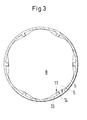
- the flushing channel 13 is in Fig. 3 visible, noticeable.
- the flushing channel 13 runs along the inner wall 6 of the storage container 5.
- the flushing element 11 is formed as a survey 14 on the inner wall of the storage container 5, which projects into the storage space, as in Fig. 3 is shown. By this survey 14, the seal between the first piston 8 and the piston seal 20 and the inner wall 6 is locally interrupted, so that flushing fluid 15 can be guided into the reservoir 4 and from there into the outlet channel 12.
- the flushing element 11 has a length which corresponds at least to the height of the first piston 8. When the first piston 8 rests on the end face 7 of the storage container 5, the flushing fluid 15 can be passed through the flushing element 11 on the first piston 8 past.
- the flushing element 11 extends on the inner wall 6 of the reservoir 5 from the end face 7 over at least the height h1 of the first piston 8 and is smaller than the total height h1 + h2 of the first piston 8 and the second piston 9.
- a height h3, h3 is greater than h1 but less than h1 + h2.
- Fig. 3 shows a section through the first piston 8, when in the in Fig. 2 shown position.
- a plurality of flushing elements 11 is provided on the inner wall 6, which are distributed on the circumference of the reservoir. These flushing elements are designed as elevations 14, such as, for example, as displacement ribs. At the elevations 14, there is a detachment of the piston seal 20, so that a flushing channel 13 is formed.
- the Flushing fluid flows through the flushing channel, or through all in Fig. 3 shown flushing channels into the reservoir 4, which consists essentially of the outlet channel 12 (see Fig. 2 ).
Landscapes
- Engineering & Computer Science (AREA)
- Mechanical Engineering (AREA)
- Feeding, Discharge, Calcimining, Fusing, And Gas-Generation Devices (AREA)
- Basic Packing Technique (AREA)
- Containers And Packaging Bodies Having A Special Means To Remove Contents (AREA)
Abstract
Description
- Die Erfindung betrifft eine Kartusche zum Austrag einer fluiden Füllmasse.
- Kartuschen zum Austragen von Füllmassen, welche aus einer oder mehreren Komponenten bestehen können, sind seit langer Zeit in Gebrauch. Hierzu wurden Lösungen entwickelt, welche die Füllmasse einmalig in einer bestimmten Dosierung austragen können, das heisst Einweglösungen. Es gibt auch Kartuschen, für die eine mehrmalige Wiederverwendung grundsätzlich zulässig ist. Das heisst, derartige Kartuschen werden nur teilweise ausgetragen und anschliessend wieder verschlossen. Beim Wiederverschliessen ist darauf zu achten, dass die Füllmasse nicht kontaminiert wird. Insbesondere bei Mehrkomponentenkartuschen, die mehrere reaktionsfähige Komponenten enthalten, würde eine Kontamination dazu führen, dass die Kartusche unbrauchbar wird, weil die reaktionsfähigen Komponenten reagieren und in der Regel aushärten und die Austragsöffnung verstopfen.
- Es besteht daher im Hinblick auf eine Wiederverwertbarkeit der Kartusche, eine Notwendigkeit, diese derart zu reinigen, dass sie frei von Resten an Füllmasse einer erneuten Verwendung zugänglich gemacht werden kann.
- Ein weiteres Problem ist der Verbleib von Füllmasse in der Kartusche nach Abschluss des Austragvorgangs. Das Austragen erfolgt nicht vollständig, sodass kleine Rückstände an reaktionsfähiger Füllmasse im Vorratsraum verbleiben, die nicht mehr entfernt werden können. Da die Füllmasse oft stark reaktionsfähig ist, ist eine Entsorgung der Kartusche samt der Füllmasse als Sondermüll erforderlich, was ein nicht unbeträchtliches Müllvolumen bedeutet.
- Ein vorbekanntes Verfahren zum Reinigen einer Kartusche besteht darin, eine Kapsel mit Neutralisationsfluid vorzusehen, wobei die Kapsel nach Abschluss des Austragens durchstochen wird, sodass sich das Neutralisationsfluid in den Vorratsraum ergiesst und allfällige Reste an Füllmasse chemisch neutralisiert. Diese Lösung ist insofern nachteilig, als Teile der Kapsel im Vorratsraum verbleiben können und die Kartusche zwar ohne Bedenken entsorgt werden kann, aber für eine Wiederverwendung nicht mehr geeignet ist.
- Daher ist es Aufgabe der Erfindung, ein Mittel vorzusehen, die Füllmasse vollständig aus dem Vorratsraum der Kartusche zu entfernen, sowie die Kartusche für eine erneute Verwendung vorzubereiten.
- Die Aufgabe der Erfindung wird mittels einer Kartusche zum Austragen einer Füllmasse gelöst, welche einen Vorratsbehälter für die Füllmasse enthält, wobei in dem Vorratsbehälter ein erster Kolben angeordnet ist, mittels welchem der Vorratsbehälter fluiddicht verschliessbar ist und eine Füllmasse im Vorratsbehälter zwischen dem ersten Kolben und einem Austrittskanal lagerbar ist, und der erste Kolben mit einer Druckkraft beaufschlagbar ist, sodass die Füllmasse aus dem Vorratsbehälter durch den Austrittskanal austragbar ist. Der Kolben weist eine der Füllmasse zugewendete Medienseite und eine gegenüberliegende Antriebsseite auf. Ein zweiter Kolben ist in dem Vorratsbehälter angeordnet, der sich auf der Antriebsseite des ersten Kolbens befindet. Der Zwischenraum zwischen dem ersten Kolben und dem zweiten Kolben ist mit einem Spülfluid gefüllt. , Ein Spülelement ist vorgesehen, sodass das Spülfluid nach Abschluss des Austragvorgangs am ersten Kolben vorbei in den Austrittskanal führbar ist.
- Allfällige Reste von Füllmasse werden somit vom Spülfluid erfasst und mit dem Spülfluid durch den Austrittskanal entsorgt. Somit sind durch das Spülfluid sind Füllmassenreste aus dem Vorratsbehälter austragbar. Hierbei bleiben keinerlei Rückstände der reaktionsfähigen Füllmasse zurück.
- Das Spülelement ist als ein Spülkanal ausgebildet, welcher verschlossen ist, solange sich die Füllmasse im Vorratsbehälter befindet. Der Spülkanal kann beispielsweise im Kolben vorgesehen sein und durch ein Absperrelement verschlossen sein, oder er kann, wie nachfolgend beschrieben, an der Innenwand des Vorratsbehälters verlaufen.
- Insbesondere kann das Spülelement ein Entlüftungsspalt sein. Ein derartiger Entlüftungsspalt kann wie in der
PCT/EP2010/057512 - Insbesondere ist das Spülelement als Erhebung an der Innenwand des Vorratsbehälters ausgebildet. Durch diese Erhebung wird die Dichtung zwischen Kolben und Innenwand lokal unterbrochen, sodass Spülfluid in den Vorratsraum und von dort in den Austrittskanal geführt werden kann. Das Spülelement weist eine Länge auf, die zumindest der Höhe des ersten Kolbens entspricht. Wenn der Kolben auf der Stirnseite des Vorratsbehälters aufliegt, kann das Spülfluid durch das Spülelement am Kolben vorbei geführt werden.
- Hierzu ist das Spülelement derart ausgestaltet, dass eine Kolbendichtung des ersten Kolbens von der Innenwand des Vorratsbehälters lösbar ist, wenn der erste Kolben sich in einer Lage befindet, in welcher die Kolbendichtung von der Erhebung erfasst wird, wodurch ein Durchgang für das Spülfluid freigebbar ist. Die Kolbendichtung kann beispielsweise als Kolbenlippe ausgebildet sein, welche auf der Innenwand des Vorratsbehälters aufliegt.
- Das Spülelement erstreckt sich an der Innenwand des Vorratsbehälters von dessen Stirnseite über zumindest die Höhe des ersten Kolbens und ist kleiner als die Gesamthöhe des ersten und des zweiten Kolbens.
- Eine Mehrzahl von Spülelementen kann vorgesehen sein. Insbesondere können mehrere Spülelemente am Umfang des Vorratsbehälters verteilt sein. Diese Spülelemente sind beispielsweise als Verdrängerrippen ausgebildet.
- Die Viskosität der Füllmasse ist vorteilhafterweise kleiner als die Viskosität des Spülfluids. Wenn das Spülfluid eine geringere Viskosität als die Füllmasse hätte, könnte das Spülfluid an der Füllmasse vorbeiströmen, ohne die Füllmasse mit auszutragen. In diesem Fall ist eine vollständige Spülung des Vorratsraums nicht gewährleistet.
- Das Volumen des Spülfluids, welches sich zwischen dem ersten und zweiten Kolben befindet, ist vorteilhafterweise zumindest so gross wie das Volumen des Austrittskanals. Hierdurch ist sichergestellt, dass die Füllmassenreste sicher aus dem Vorratsraum und dem Austrittskanal entfernt sind, wenn die Spülung abgeschlossen ist.
- Der Vorratsbehälter kann insbesondere eine Innenwand und eine Stirnseite aufweisen, wobei die Stirnseite eine Austrittsöffnung aufweist, an welche der Austrittskanal anschliesst, wobei der Durchmesser der Austrittsöffnung maximal ein Drittel des Durchmessers des Vorratsbehälters beträgt.
- Die Austrittsöffnung ist das Eintrittsende des Austrittskanals und der Austrittskanal weist ein Austrittsende auf, an welchen ein Mischelement anschliessbar ist.
- Insbesondere kann die Kartusche als Mehrkomponentenkartusche ausgebildet sein, beispielsweise in der Bauweise der
PCT/EP2010/057512 - Nachfolgend wird die Erfindung anhand der Zeichnungen erläutert. Es zeigen:
- Fig. 1
- eine schematische Darstellung einer erfindungsgemässen Kartusche
- Fig. 2
- die Kartusche der
Fig. 1 nach dem Austragen der Füllmasse - Fig. 3
- einen Schnitt durch eine erfindungsgemässe Kartusche
-
Fig. 1 zeigt ein bevorzugtes Ausführungsbeispiel der Erfindung, eine Kartusche 1 zum Austragen einer Füllmasse 3. Die Füllmasse 3 ist in der Regel eine Flüssigkeit, welche sich in einem Vorratsbehälter 5 befindet. Der Vorratsbehälter ist Teil der Kartusche und weist eine Innenwand 6 und eine Stirnseite 7 auf. Die Innenwand 6 ist koaxial zur Längsachse 10 der Kartusche angeordnet. Die Stirnseite 7 enthält einen Austrittskanal 12, durch welchen die Füllmasse 3 aus dem Vorratsbehälter 5 ausgetragen wird. In dem Vorratsbehälter 5 ist ein erster Kolben 8 angeordnet, mittels welchem der Vorratsbehälter 5 fluiddicht verschliessbar ist. Durch den ersten Kolben 8, den Vorratsbehälter 5 und den Austrittskanal 12, welcher durch ein nicht dargestelltes Verschlusselement verschliessbar ist, wird ein Vorratsraum 4 gebildet, in welchem die Füllmasse 3 lagerbar ist. - Der erste Kolben 9 weist eine der Füllmasse 3 zugewendete Medienseite 18 und eine der Medienseite 18 gegenüberliegende Antriebsseite 19 auf. Der erste Kolben 8 ist auf der Antriebsseite 19 mit einer Druckkraft beaufschlagbar, sodass die Füllmasse 3 aus dem Vorratsbehälter 5 durch den Austrittskanal 12 austragbar ist, indem der erste Kolben 8 entlang der Innenwand 6 in Richtung des Austrittskanals 12 bewegt wird.
- Wenn der erste Kolben 8 die Stirnseite 7 erreicht, ist der Vorgang des Austragens abgeschlossen. Zwischen dem ersten Kolben 8 und der Stirnseite 7 sowie im Austrittskanal 12 befindet sich noch Füllmasse 3. Wenn diese Füllmasse 3 eine reaktive Komponente enthält, kann es zu einer chemischen Reaktion im Austrittskanal 12 kommen, welcher mit der Luft der Umgebung in Kontakt ist. Des weiteren stellt eine reaktive Füllmasse nicht selten ein Risiko für die Umwelt dar, sodass eine mit derartiger reaktiver Füllmasse 3 kontaminierte Kartusche 1 bisher als Sondermüll entsorgt werden musste. Daher wird erfindungsgemäss eine Spülung vorgesehen, damit die Füllmasse vollständig aus dem Vorratsraum ausgetragen wird.
- Hierzu ist ein zweiter Kolben 9 in dem Vorratsbehälter 5 angeordnet. Der zweite Kolben 9 ist auf der Antriebsseite 19 des ersten Kolbens 8 angeordnet. Zwischen dem ersten Kolben 8 und dem zweiten Kolben 9 befindet sich ein Spülfluid 15. Der erste Kolben weist eine Kolbendichtung 20 und der zweite Kolben weist eine Kolbendichtung 30 auf. Das Spülfluid 15 befindet sich zwischen dem ersten Kolben 8 und dem zweiten Kolben 9. Ein Austreten des Spülfluids in den Vorratsraum 5 wird durch die Kolbendichtung 20 verhindert. Ein Austreten des Spülfluids 15 in die Umgebung wird durch die Kolbendichtung 30 verhindert.
- Der zweite Kolben weist eine Medienseite 28 und eine Antriebsseite 29 auf, wobei die Medienseite 28 in Kontakt mit dem Spülfluid 15 ist. Die Antriebsseite 19 des ersten Kolbens 8 ist ebenfalls in Kontakt mit dem Spülfluid 15. Das Spülfluid 15 ist im wesentlichen inkompressibel und verbleibt in dem Zwischenraum 16 zwischen der Medienseite 28 des zweiten Kolbens 9 und der Antriebsseite 19 des ersten Kolbens 8, solange die Kolbendichtungen 20, 30 vollständig auf der Innenwand 6 des Vorratsbehälters 5 aufliegen.
- Zum Austrag der Füllmasse 3 wird der zweite Kolben 9 mit einer Druckkraft beaufschlagt. Diese Druckkraft kann beispielsweise durch ein Druckfluid oder durch einen Stössel aufgebracht werden. Beide Varianten sind dem Fachmann bekannt und werden daher zeichnerisch nicht dargestellt. Wenn der zweite Kolben mit einer Druckkraft beaufschlagt wird, wird er in Richtung der Stirnseite 7 verschoben. Gleichzeitig wird der erste Kolben 8 und das im Zwischenraum 16 befindliche Spülfluid 15 mit verschoben. Die Füllmasse 3 verlässt den Vorratsbehälter 5 durch eine Austrittsöffnung 17 und den Austrittskanal 12.
- Um die nach Beendigung des Austragvorgangs im Vorratsraum 4 verbleibende Füllmasse 3 zu entfernen, ist ein Spülelement 11 vorgesehen , sodass das Spülfluid 15 nach Abschluss des Austragvorgangs am ersten Kolben 8 vorbei in den Austrittskanal 12 führbar ist. Allfällige Reste von Füllmasse 3 werden somit vom Spülfluid 15 erfasst und mit dem Spülfluid 15 durch den Austrittskanal 12 ausgeschoben. Somit sind durch das Spülfluid 15 Füllmassenreste vollständig aus dem Vorratsbehälter entfernbar, sodass keinerlei Rückstände der reaktionsfähigen Füllmasse im Vorratsraum 4 zurückbleiben.
- Gemäss
Fig. 1 oderFig. 2 wird durch das Spülelement 11 ein Spülkanal 13 ausgebildet, welcher verschlossen ist, solange sich die Füllmasse im Vorratsbehälter 5 befindet. Der Spülkanal 13 ist inFig. 3 sichtbar. Der Spülkanal 13 verläuft entlang der Innenwand 6 des Vorratsbehälters 5. - Das Spülelement 11 ist als Erhebung 14 an der Innenwand des Vorratsbehälters 5 ausgebildet, welche in den Vorratsraum hinein ragt, wie in
Fig. 3 gezeigt ist. Durch diese Erhebung 14 wird die Abdichtung zwischen dem ersten Kolben 8 bzw. dessen Kolbendichtung 20 und der Innenwand 6 lokal unterbrochen, sodass Spülfluid 15 in den Vorratsraum 4 und von dort in den Austrittskanal 12 geführt werden kann. Das Spülelement 11 weist eine Länge auf, die zumindest der Höhe des ersten Kolbens 8 entspricht. Wenn der erste Kolben 8 auf der Stirnseite 7 des Vorratsbehälters 5 aufliegt, kann das Spülfluid 15 durch das Spülelement 11 am ersten Kolben 8 vorbei geführt werden. - Das Spülelement 11 erstreckt sich an der Innenwand 6 des Vorratsbehälters 5 von dessen Stirnseite 7 über zumindest die Höhe h1 des ersten Kolbens 8 und ist kleiner als die Gesamthöhe h1+h2 des ersten Kolbens 8 und des zweiten Kolbens 9. Wenn das Spülelement 11 eine Höhe h3 aufweist, gilt, dass h3 grösser ist als h1 aber kleiner als h1 + h2.
-
Fig. 3 zeigt einen Schnitt durch den ersten Kolben 8, wenn er sich in der inFig. 2 gezeigten Stellung befindet. Eine Mehrzahl von Spülelementen 11 ist an der Innenwand 6 vorgesehen, die am Umfang des Vorratsbehälters verteilt sind. Diese Spülelemente sind als Erhebungen 14 ausgebildet, wie beispielsweise als Verdrängerrippen. An den Erhebungen 14 kommt es zum Ablösen der Kolbendichtung 20, sodass ein Spülkanal 13 entsteht. Das Spülfluid fliesst durch den Spülkanal, bzw. durch alle inFig. 3 gezeigten Spülkanäle in den Vorratsraum 4, der im wesentlichen aus dem Austrittskanal 12 besteht (sieheFig. 2 ).
Claims (15)
- Kartusche (1) zum Austragen einer Füllmasse (3), welche einen Vorratsbehälter (5) für die Füllmasse (3) enthält, wobei in dem Vorratsbehälter (5) ein erster Kolben (8) angeordnet ist, mittels welchem der Vorratsbehälter (5) fluiddicht verschliessbar ist und eine Füllmasse(3) im Vorratsbehälter (5) zwischen dem ersten Kolben (8) und einem Austrittskanal (12) lagerbar ist, und der erste Kolben (8) mit einer Druckkraft beaufschlagbar ist, sodass die Füllmasse (3) aus dem Vorratsbehälter (5) durch den Austrittskanal (12) austragbar ist, wobei der Vorratsbehälter (5) eine Innenwand (6) und eine Stirnseite (7) aufweist, wobei die Stirnseite (7) eine Austrittsöffnung (17) aufweist, an welche der Austrittskanal (12) anschliesst, wobei der Durchmesser der Austrittsöffnung (17) kleiner als der Durchmesser des Vorratsbehälters (5) istund der erste Kolben (8) eine der Füllmasse (3) zugewendete Medienseite (18) aufweist und eine gegenüberliegende Antriebsseite (19) aufweist, dadurch gekennzeichnet, dass ein zweiter Kolben (9) in dem Vorratsbehälter (5) angeordnet ist, der sich auf der Antriebsseite (19) des ersten Kolbens (8) befindet und sich zwischen dem ersten Kolben (8) und dem zweiten Kolben (9) ein Spülfluid (15) befindet, wobei ein Spülelement (11) vorgesehen ist, mittels welchem das Spülfluid (15) nach Abschluss des Austragvorgangs am ersten Kolben (8) vorbei in den Austrittskanal (12) führbar ist.
- Kartusche (1) nach Anspruch 1, wobei durch das Spülfluid (15) Füllmassenreste (3) aus dem Vorratsbehälter (5) austragbar sind.
- Kartusche (1) nach einem der vorhergehenden Ansprüche, wobei das Spülelement (11) als ein Spülkanal (13) ausgebildet ist, welcher verschlossen ist, solange sich die Füllmasse (3) im Vorratsbehälter (5) befindet.
- Kartusche (1) nach einem der vorhergehenden Ansprüche, wobei das Spülelement (11) ein Entlüftungsspalt ist.
- Kartusche (1) nach einem der vorhergehenden Ansprüche, wobei das Spülelement (11) an der Innenwand (6) des Vorratsbehälters (5) angeordnet ist.
- Kartusche (1) nach einem der vorhergehenden Ansprüche, wobei das Spülelement (11) als Erhebung (14) an der Innenwand (6) des Vorratsbehälters (5) ausgebildet ist.
- Kartusche (1) nach einem der vorhergehenden Ansprüche, wobei das Spülelement (11) eine Länge aufweist, die zumindest der Höhe des ersten Kolbens (8) entspricht.
- Kartusche (1) nach Anspruch 6 oder 7, wobei eine Kolbendichtung (20) des ersten Kolbens (8) von der Innenwand (6) des Vorratsbehälters (5) lösbar ist, wenn der erste Kolben (8) sich in einer Lage befindet, in welcher die Kolbendichtung (20) von der Erhebung (14) erfasst wird, wodurch ein Durchgang für das Spülfluid (11) freigebbar ist.
- Kartusche (1) nach einem der Ansprüche 6 bis 8, wobei das Spülelement (11) sich an der Innenwand (6) des Vorratsbehälters (5) von dessen Stirnseite (7) über zumindest die Höhe des ersten Kolbens (8) erstreckt und kleiner als die Gesamthöhe des ersten Kolbens (8) und des zweiten Kolbens (9) ist.
- Kartusche (1) nach einem der vorhergehenden Ansprüche, wobei eine Mehrzahl von Spülelementen (11) vorgesehen ist.
- Kartusche (1) nach einem der vorhergehenden Ansprüche, wobei die Viskosität der Füllmasse (3) kleiner als die Viskosität des Spülfluids (15) ist.
- Kartusche nach einem der vorhergehenden Ansprüche, wobei das Volumen des Spülfluids (15), welches sich zwischen dem ersten Kolben (8) und zweiten Kolben (9) befindet, zumindest so gross wie das Volumen des Austrittskanals (12) ist.
- Kartusche (1) nach einem der vorhergehenden Ansprüche, , wobei der Durchmesser der Austrittsöffnung (17) maximal ein Drittel des Durchmessers des Vorratsbehälters (5) beträgt.
- Kartusche (1) nach einem der vorhergehenden Ansprüche, wobei die Austrittsöffnung (17) das Eintrittsende des Austrittskanals (12) ist und der Austrittskanal (12) ein Austrittsende aufweist, an welchen ein Mischelement anschliessbar ist.
- Kartusche (1) nach einem der vorhergehenden Ansprüche, wobei die Kartusche als Mehrkomponentenkartusche ausgebildet ist.
Priority Applications (1)
| Application Number | Priority Date | Filing Date | Title |
|---|---|---|---|
| EP11170348A EP2407394B1 (de) | 2010-07-16 | 2011-06-17 | Kartusche mit Spülung |
Applications Claiming Priority (2)
| Application Number | Priority Date | Filing Date | Title |
|---|---|---|---|
| EP10169853 | 2010-07-16 | ||
| EP11170348A EP2407394B1 (de) | 2010-07-16 | 2011-06-17 | Kartusche mit Spülung |
Publications (2)
| Publication Number | Publication Date |
|---|---|
| EP2407394A1 true EP2407394A1 (de) | 2012-01-18 |
| EP2407394B1 EP2407394B1 (de) | 2013-01-16 |
Family
ID=42697563
Family Applications (1)
| Application Number | Title | Priority Date | Filing Date |
|---|---|---|---|
| EP11170348A Not-in-force EP2407394B1 (de) | 2010-07-16 | 2011-06-17 | Kartusche mit Spülung |
Country Status (5)
| Country | Link |
|---|---|
| US (1) | US20120012615A1 (de) |
| EP (1) | EP2407394B1 (de) |
| KR (1) | KR20120008465A (de) |
| CN (1) | CN102336309A (de) |
| ES (1) | ES2399342T3 (de) |
Families Citing this family (3)
| Publication number | Priority date | Publication date | Assignee | Title |
|---|---|---|---|---|
| JP6523610B2 (ja) * | 2014-03-20 | 2019-06-05 | 大和特殊硝子株式会社 | 注射器 |
| EP3632575A1 (de) * | 2018-10-02 | 2020-04-08 | Sulzer Mixpac AG | Wiederverwendbarer kartuschenkolben |
| JP7807272B2 (ja) * | 2022-03-22 | 2026-01-27 | オルガノ株式会社 | 管理システム、管理装置、管理方法およびプログラム |
Citations (1)
| Publication number | Priority date | Publication date | Assignee | Title |
|---|---|---|---|---|
| DE8310839U1 (de) * | 1983-04-13 | 1985-01-24 | Eppendorf Gerätebau Netheler + Hinz GmbH, 2000 Hamburg | Konzentratkapsel fuer wenigstens eine Zugabe zu einem Loesungsmittel und Bestaetigungseinrichtung fuer eine solche Konzentratkapsel |
Family Cites Families (5)
| Publication number | Priority date | Publication date | Assignee | Title |
|---|---|---|---|---|
| US4439184A (en) * | 1982-05-03 | 1984-03-27 | Concord Laboratories, Inc. | Two-dose syringe |
| US4715854A (en) * | 1986-07-17 | 1987-12-29 | Vaillancourt Vincent L | Multidose disposable syringe and method of filling same |
| US5429610A (en) * | 1993-11-19 | 1995-07-04 | Vaillancourt; Vincent L. | Dual chamber syringe for collecting samples and blood collecting system |
| US5522804A (en) * | 1994-02-15 | 1996-06-04 | Lynn; Lawrence A. | Aspiration, mixing, and injection syringe |
| US8075533B2 (en) * | 2005-05-02 | 2011-12-13 | Preventiv, Inc. | Autoflush syringe |
-
2011
- 2011-06-17 EP EP11170348A patent/EP2407394B1/de not_active Not-in-force
- 2011-06-17 ES ES11170348T patent/ES2399342T3/es active Active
- 2011-07-15 US US13/135,849 patent/US20120012615A1/en not_active Abandoned
- 2011-07-15 KR KR1020110070337A patent/KR20120008465A/ko not_active Withdrawn
- 2011-07-15 CN CN2011101984057A patent/CN102336309A/zh active Pending
Patent Citations (1)
| Publication number | Priority date | Publication date | Assignee | Title |
|---|---|---|---|---|
| DE8310839U1 (de) * | 1983-04-13 | 1985-01-24 | Eppendorf Gerätebau Netheler + Hinz GmbH, 2000 Hamburg | Konzentratkapsel fuer wenigstens eine Zugabe zu einem Loesungsmittel und Bestaetigungseinrichtung fuer eine solche Konzentratkapsel |
Also Published As
| Publication number | Publication date |
|---|---|
| CN102336309A (zh) | 2012-02-01 |
| EP2407394B1 (de) | 2013-01-16 |
| ES2399342T3 (es) | 2013-03-27 |
| US20120012615A1 (en) | 2012-01-19 |
| KR20120008465A (ko) | 2012-01-30 |
Similar Documents
| Publication | Publication Date | Title |
|---|---|---|
| WO2001032242A1 (de) | Mehrkammer-ampulle zum ausgeben eines aus mehreren substanzen bestehenden gemisches | |
| EP2410940B1 (de) | Spritze zur einmaligen verwendung | |
| EP2718201B1 (de) | Satz von mehrkomponentenkartuschen | |
| DE102009048352A1 (de) | Kettenrad mit Schmierstoffzuführung | |
| WO2015007792A1 (de) | Dosierapparat zum handgesteuerten dosieren eines lichtaushärtenden materials | |
| EP2407394B1 (de) | Kartusche mit Spülung | |
| DE3129142A1 (de) | Ausgabegeraet fuer ein produkt von hoher viskositaet | |
| EP2696794B1 (de) | Abgabebehälter für dentalmasse | |
| DE102009050053A1 (de) | Schlauchpumpe und Fluidspender mit einer solchen | |
| DE102005000757B4 (de) | Zweikammerkartusche für zweikomponentige plastische Massen mit axial hintereinander angeordneten Kammern | |
| EP2050510B1 (de) | Auspressvorrichtung | |
| WO2016046099A1 (de) | Applikationsvorrichtung für mehrkomponentenstoffe | |
| EP2773406B1 (de) | Einwegdosierer | |
| WO2010118764A1 (de) | Flüssigkeitspumpengerät | |
| DE102008001313B9 (de) | Tropfkappe | |
| EP2184113B1 (de) | Auspressvorrichtung | |
| DE10234435A1 (de) | Mit Fluidwerkstoffen gefüllte Kartusche und Vorrichtung zum Laden einer solchen Kartusche in eine Fluidabgabevorrichtung | |
| DE202015104116U1 (de) | Spülvorrichtung für die Schamteile des menschlichen Körpers | |
| DE19742888A1 (de) | Auftragsvorrichtung | |
| DE102023131450B3 (de) | Folgeplatte | |
| DE102019103515B4 (de) | Flaschenverschluss für eine Flasche mit flexibler Wandung zur dosierten Abgabe einer Flüssigkeit | |
| EP2365878A1 (de) | Pipette | |
| EP2324752A2 (de) | System zur Befüllung einer Dosiereinrichtung einer Spülmaschine | |
| DE102005045359B4 (de) | Applikationsgerät für Dentalmassen | |
| DE102023100940A1 (de) | Verschlussvorrichtung in Form einer Kappe zum fluiddichten Verschließen einer Düse und System mit einer Verschlussvorrichtung und einer Düse |
Legal Events
| Date | Code | Title | Description |
|---|---|---|---|
| AK | Designated contracting states |
Kind code of ref document: A1 Designated state(s): AL AT BE BG CH CY CZ DE DK EE ES FI FR GB GR HR HU IE IS IT LI LT LU LV MC MK MT NL NO PL PT RO RS SE SI SK SM TR |
|
| AX | Request for extension of the european patent |
Extension state: BA ME |
|
| PUAI | Public reference made under article 153(3) epc to a published international application that has entered the european phase |
Free format text: ORIGINAL CODE: 0009012 |
|
| GRAP | Despatch of communication of intention to grant a patent |
Free format text: ORIGINAL CODE: EPIDOSNIGR1 |
|
| 17P | Request for examination filed |
Effective date: 20120718 |
|
| RIC1 | Information provided on ipc code assigned before grant |
Ipc: B65D 83/00 20060101AFI20120731BHEP |
|
| GRAS | Grant fee paid |
Free format text: ORIGINAL CODE: EPIDOSNIGR3 |
|
| GRAA | (expected) grant |
Free format text: ORIGINAL CODE: 0009210 |
|
| AK | Designated contracting states |
Kind code of ref document: B1 Designated state(s): AL AT BE BG CH CY CZ DE DK EE ES FI FR GB GR HR HU IE IS IT LI LT LU LV MC MK MT NL NO PL PT RO RS SE SI SK SM TR |
|
| REG | Reference to a national code |
Ref country code: GB Ref legal event code: FG4D Free format text: NOT ENGLISH |
|
| REG | Reference to a national code |
Ref country code: CH Ref legal event code: EP |
|
| REG | Reference to a national code |
Ref country code: IE Ref legal event code: FG4D Free format text: LANGUAGE OF EP DOCUMENT: GERMAN |
|
| REG | Reference to a national code |
Ref country code: AT Ref legal event code: REF Ref document number: 593768 Country of ref document: AT Kind code of ref document: T Effective date: 20130215 Ref country code: CH Ref legal event code: EP |
|
| REG | Reference to a national code |
Ref country code: DE Ref legal event code: R096 Ref document number: 502011000359 Country of ref document: DE Effective date: 20130314 |
|
| REG | Reference to a national code |
Ref country code: ES Ref legal event code: FG2A Ref document number: 2399342 Country of ref document: ES Kind code of ref document: T3 Effective date: 20130327 |
|
| REG | Reference to a national code |
Ref country code: NL Ref legal event code: VDEP Effective date: 20130116 |
|
| REG | Reference to a national code |
Ref country code: LT Ref legal event code: MG4D |
|
| PG25 | Lapsed in a contracting state [announced via postgrant information from national office to epo] |
Ref country code: LT Free format text: LAPSE BECAUSE OF FAILURE TO SUBMIT A TRANSLATION OF THE DESCRIPTION OR TO PAY THE FEE WITHIN THE PRESCRIBED TIME-LIMIT Effective date: 20130116 Ref country code: NO Free format text: LAPSE BECAUSE OF FAILURE TO SUBMIT A TRANSLATION OF THE DESCRIPTION OR TO PAY THE FEE WITHIN THE PRESCRIBED TIME-LIMIT Effective date: 20130416 Ref country code: BG Free format text: LAPSE BECAUSE OF FAILURE TO SUBMIT A TRANSLATION OF THE DESCRIPTION OR TO PAY THE FEE WITHIN THE PRESCRIBED TIME-LIMIT Effective date: 20130416 Ref country code: IS Free format text: LAPSE BECAUSE OF FAILURE TO SUBMIT A TRANSLATION OF THE DESCRIPTION OR TO PAY THE FEE WITHIN THE PRESCRIBED TIME-LIMIT Effective date: 20130516 Ref country code: SE Free format text: LAPSE BECAUSE OF FAILURE TO SUBMIT A TRANSLATION OF THE DESCRIPTION OR TO PAY THE FEE WITHIN THE PRESCRIBED TIME-LIMIT Effective date: 20130116 |
|
| PG25 | Lapsed in a contracting state [announced via postgrant information from national office to epo] |
Ref country code: SI Free format text: LAPSE BECAUSE OF FAILURE TO SUBMIT A TRANSLATION OF THE DESCRIPTION OR TO PAY THE FEE WITHIN THE PRESCRIBED TIME-LIMIT Effective date: 20130116 Ref country code: FI Free format text: LAPSE BECAUSE OF FAILURE TO SUBMIT A TRANSLATION OF THE DESCRIPTION OR TO PAY THE FEE WITHIN THE PRESCRIBED TIME-LIMIT Effective date: 20130116 Ref country code: NL Free format text: LAPSE BECAUSE OF FAILURE TO SUBMIT A TRANSLATION OF THE DESCRIPTION OR TO PAY THE FEE WITHIN THE PRESCRIBED TIME-LIMIT Effective date: 20130116 Ref country code: PT Free format text: LAPSE BECAUSE OF FAILURE TO SUBMIT A TRANSLATION OF THE DESCRIPTION OR TO PAY THE FEE WITHIN THE PRESCRIBED TIME-LIMIT Effective date: 20130516 Ref country code: GR Free format text: LAPSE BECAUSE OF FAILURE TO SUBMIT A TRANSLATION OF THE DESCRIPTION OR TO PAY THE FEE WITHIN THE PRESCRIBED TIME-LIMIT Effective date: 20130417 Ref country code: PL Free format text: LAPSE BECAUSE OF FAILURE TO SUBMIT A TRANSLATION OF THE DESCRIPTION OR TO PAY THE FEE WITHIN THE PRESCRIBED TIME-LIMIT Effective date: 20130116 Ref country code: LV Free format text: LAPSE BECAUSE OF FAILURE TO SUBMIT A TRANSLATION OF THE DESCRIPTION OR TO PAY THE FEE WITHIN THE PRESCRIBED TIME-LIMIT Effective date: 20130116 |
|
| PG25 | Lapsed in a contracting state [announced via postgrant information from national office to epo] |
Ref country code: HR Free format text: LAPSE BECAUSE OF FAILURE TO SUBMIT A TRANSLATION OF THE DESCRIPTION OR TO PAY THE FEE WITHIN THE PRESCRIBED TIME-LIMIT Effective date: 20130116 Ref country code: RS Free format text: LAPSE BECAUSE OF FAILURE TO SUBMIT A TRANSLATION OF THE DESCRIPTION OR TO PAY THE FEE WITHIN THE PRESCRIBED TIME-LIMIT Effective date: 20130116 |
|
| PG25 | Lapsed in a contracting state [announced via postgrant information from national office to epo] |
Ref country code: EE Free format text: LAPSE BECAUSE OF FAILURE TO SUBMIT A TRANSLATION OF THE DESCRIPTION OR TO PAY THE FEE WITHIN THE PRESCRIBED TIME-LIMIT Effective date: 20130116 Ref country code: RO Free format text: LAPSE BECAUSE OF FAILURE TO SUBMIT A TRANSLATION OF THE DESCRIPTION OR TO PAY THE FEE WITHIN THE PRESCRIBED TIME-LIMIT Effective date: 20130116 Ref country code: DK Free format text: LAPSE BECAUSE OF FAILURE TO SUBMIT A TRANSLATION OF THE DESCRIPTION OR TO PAY THE FEE WITHIN THE PRESCRIBED TIME-LIMIT Effective date: 20130116 Ref country code: SK Free format text: LAPSE BECAUSE OF FAILURE TO SUBMIT A TRANSLATION OF THE DESCRIPTION OR TO PAY THE FEE WITHIN THE PRESCRIBED TIME-LIMIT Effective date: 20130116 Ref country code: CZ Free format text: LAPSE BECAUSE OF FAILURE TO SUBMIT A TRANSLATION OF THE DESCRIPTION OR TO PAY THE FEE WITHIN THE PRESCRIBED TIME-LIMIT Effective date: 20130116 |
|
| PLBE | No opposition filed within time limit |
Free format text: ORIGINAL CODE: 0009261 |
|
| STAA | Information on the status of an ep patent application or granted ep patent |
Free format text: STATUS: NO OPPOSITION FILED WITHIN TIME LIMIT |
|
| PG25 | Lapsed in a contracting state [announced via postgrant information from national office to epo] |
Ref country code: CY Free format text: LAPSE BECAUSE OF FAILURE TO SUBMIT A TRANSLATION OF THE DESCRIPTION OR TO PAY THE FEE WITHIN THE PRESCRIBED TIME-LIMIT Effective date: 20130116 |
|
| 26N | No opposition filed |
Effective date: 20131017 |
|
| BERE | Be: lapsed |
Owner name: SULZER MIXPAC A.G. Effective date: 20130630 |
|
| PG25 | Lapsed in a contracting state [announced via postgrant information from national office to epo] |
Ref country code: IT Free format text: LAPSE BECAUSE OF FAILURE TO SUBMIT A TRANSLATION OF THE DESCRIPTION OR TO PAY THE FEE WITHIN THE PRESCRIBED TIME-LIMIT Effective date: 20130116 |
|
| PG25 | Lapsed in a contracting state [announced via postgrant information from national office to epo] |
Ref country code: MC Free format text: LAPSE BECAUSE OF FAILURE TO SUBMIT A TRANSLATION OF THE DESCRIPTION OR TO PAY THE FEE WITHIN THE PRESCRIBED TIME-LIMIT Effective date: 20130116 |
|
| REG | Reference to a national code |
Ref country code: DE Ref legal event code: R097 Ref document number: 502011000359 Country of ref document: DE Effective date: 20131017 |
|
| REG | Reference to a national code |
Ref country code: DE Ref legal event code: R119 Ref document number: 502011000359 Country of ref document: DE Effective date: 20140101 |
|
| REG | Reference to a national code |
Ref country code: IE Ref legal event code: MM4A |
|
| REG | Reference to a national code |
Ref country code: FR Ref legal event code: ST Effective date: 20140228 |
|
| PG25 | Lapsed in a contracting state [announced via postgrant information from national office to epo] |
Ref country code: BE Free format text: LAPSE BECAUSE OF NON-PAYMENT OF DUE FEES Effective date: 20130630 |
|
| PG25 | Lapsed in a contracting state [announced via postgrant information from national office to epo] |
Ref country code: DE Free format text: LAPSE BECAUSE OF NON-PAYMENT OF DUE FEES Effective date: 20140101 Ref country code: IE Free format text: LAPSE BECAUSE OF NON-PAYMENT OF DUE FEES Effective date: 20130617 |
|
| PG25 | Lapsed in a contracting state [announced via postgrant information from national office to epo] |
Ref country code: FR Free format text: LAPSE BECAUSE OF NON-PAYMENT OF DUE FEES Effective date: 20130701 |
|
| REG | Reference to a national code |
Ref country code: ES Ref legal event code: FD2A Effective date: 20140707 |
|
| PGFP | Annual fee paid to national office [announced via postgrant information from national office to epo] |
Ref country code: CH Payment date: 20140701 Year of fee payment: 4 |
|
| PG25 | Lapsed in a contracting state [announced via postgrant information from national office to epo] |
Ref country code: ES Free format text: LAPSE BECAUSE OF NON-PAYMENT OF DUE FEES Effective date: 20130618 |
|
| PG25 | Lapsed in a contracting state [announced via postgrant information from national office to epo] |
Ref country code: MT Free format text: LAPSE BECAUSE OF FAILURE TO SUBMIT A TRANSLATION OF THE DESCRIPTION OR TO PAY THE FEE WITHIN THE PRESCRIBED TIME-LIMIT Effective date: 20130116 |
|
| PG25 | Lapsed in a contracting state [announced via postgrant information from national office to epo] |
Ref country code: SM Free format text: LAPSE BECAUSE OF FAILURE TO SUBMIT A TRANSLATION OF THE DESCRIPTION OR TO PAY THE FEE WITHIN THE PRESCRIBED TIME-LIMIT Effective date: 20130116 |
|
| PG25 | Lapsed in a contracting state [announced via postgrant information from national office to epo] |
Ref country code: TR Free format text: LAPSE BECAUSE OF FAILURE TO SUBMIT A TRANSLATION OF THE DESCRIPTION OR TO PAY THE FEE WITHIN THE PRESCRIBED TIME-LIMIT Effective date: 20130116 |
|
| PG25 | Lapsed in a contracting state [announced via postgrant information from national office to epo] |
Ref country code: MK Free format text: LAPSE BECAUSE OF FAILURE TO SUBMIT A TRANSLATION OF THE DESCRIPTION OR TO PAY THE FEE WITHIN THE PRESCRIBED TIME-LIMIT Effective date: 20130116 Ref country code: LU Free format text: LAPSE BECAUSE OF NON-PAYMENT OF DUE FEES Effective date: 20130617 Ref country code: HU Free format text: LAPSE BECAUSE OF FAILURE TO SUBMIT A TRANSLATION OF THE DESCRIPTION OR TO PAY THE FEE WITHIN THE PRESCRIBED TIME-LIMIT; INVALID AB INITIO Effective date: 20110617 |
|
| REG | Reference to a national code |
Ref country code: CH Ref legal event code: PL |
|
| GBPC | Gb: european patent ceased through non-payment of renewal fee |
Effective date: 20150617 |
|
| PG25 | Lapsed in a contracting state [announced via postgrant information from national office to epo] |
Ref country code: LI Free format text: LAPSE BECAUSE OF NON-PAYMENT OF DUE FEES Effective date: 20150630 Ref country code: CH Free format text: LAPSE BECAUSE OF NON-PAYMENT OF DUE FEES Effective date: 20150630 Ref country code: GB Free format text: LAPSE BECAUSE OF NON-PAYMENT OF DUE FEES Effective date: 20150617 |
|
| REG | Reference to a national code |
Ref country code: AT Ref legal event code: MM01 Ref document number: 593768 Country of ref document: AT Kind code of ref document: T Effective date: 20160617 |
|
| PG25 | Lapsed in a contracting state [announced via postgrant information from national office to epo] |
Ref country code: AT Free format text: LAPSE BECAUSE OF NON-PAYMENT OF DUE FEES Effective date: 20160617 |
|
| PG25 | Lapsed in a contracting state [announced via postgrant information from national office to epo] |
Ref country code: AL Free format text: LAPSE BECAUSE OF FAILURE TO SUBMIT A TRANSLATION OF THE DESCRIPTION OR TO PAY THE FEE WITHIN THE PRESCRIBED TIME-LIMIT Effective date: 20130116 |