EP2407181A1 - Verdampfer zum Sterilisieren von Kunststoffbehältnissen - Google Patents
Verdampfer zum Sterilisieren von Kunststoffbehältnissen Download PDFInfo
- Publication number
- EP2407181A1 EP2407181A1 EP11172637A EP11172637A EP2407181A1 EP 2407181 A1 EP2407181 A1 EP 2407181A1 EP 11172637 A EP11172637 A EP 11172637A EP 11172637 A EP11172637 A EP 11172637A EP 2407181 A1 EP2407181 A1 EP 2407181A1
- Authority
- EP
- European Patent Office
- Prior art keywords
- housing
- evaporator
- line
- hydrogen peroxide
- medium
- Prior art date
- Legal status (The legal status is an assumption and is not a legal conclusion. Google has not performed a legal analysis and makes no representation as to the accuracy of the status listed.)
- Granted
Links
Images



Classifications
-
- A—HUMAN NECESSITIES
- A61—MEDICAL OR VETERINARY SCIENCE; HYGIENE
- A61L—METHODS OR APPARATUS FOR STERILISING MATERIALS OR OBJECTS IN GENERAL; DISINFECTION, STERILISATION OR DEODORISATION OF AIR; CHEMICAL ASPECTS OF BANDAGES, DRESSINGS, ABSORBENT PADS OR SURGICAL ARTICLES; MATERIALS FOR BANDAGES, DRESSINGS, ABSORBENT PADS OR SURGICAL ARTICLES
- A61L2/00—Disinfection or sterilisation of materials or objects, in general; Accessories therefor
- A61L2/16—Disinfection or sterilisation of materials or objects, in general; Accessories therefor using chemical substances
- A61L2/20—Gaseous substances, e.g. vapours
- A61L2/208—Hydrogen peroxide
-
- B—PERFORMING OPERATIONS; TRANSPORTING
- B01—PHYSICAL OR CHEMICAL PROCESSES OR APPARATUS IN GENERAL
- B01B—BOILING; BOILING APPARATUS ; EVAPORATION; EVAPORATION APPARATUS
- B01B1/00—Boiling; Boiling apparatus for physical or chemical purposes ; Evaporation in general
- B01B1/005—Evaporation for physical or chemical purposes; Evaporation apparatus therefor, e.g. evaporation of liquids for gas phase reactions
-
- B—PERFORMING OPERATIONS; TRANSPORTING
- B65—CONVEYING; PACKING; STORING; HANDLING THIN OR FILAMENTARY MATERIAL
- B65B—MACHINES, APPARATUS OR DEVICES FOR, OR METHODS OF, PACKAGING ARTICLES OR MATERIALS; UNPACKING
- B65B55/00—Preserving, protecting or purifying packages or package contents in association with packaging
- B65B55/02—Sterilising, e.g. of complete packages
- B65B55/04—Sterilising wrappers or receptacles prior to, or during, packaging
- B65B55/06—Sterilising wrappers or receptacles prior to, or during, packaging by heat
-
- B—PERFORMING OPERATIONS; TRANSPORTING
- B65—CONVEYING; PACKING; STORING; HANDLING THIN OR FILAMENTARY MATERIAL
- B65B—MACHINES, APPARATUS OR DEVICES FOR, OR METHODS OF, PACKAGING ARTICLES OR MATERIALS; UNPACKING
- B65B55/00—Preserving, protecting or purifying packages or package contents in association with packaging
- B65B55/02—Sterilising, e.g. of complete packages
- B65B55/04—Sterilising wrappers or receptacles prior to, or during, packaging
- B65B55/10—Sterilising wrappers or receptacles prior to, or during, packaging by liquids or gases
-
- A—HUMAN NECESSITIES
- A61—MEDICAL OR VETERINARY SCIENCE; HYGIENE
- A61L—METHODS OR APPARATUS FOR STERILISING MATERIALS OR OBJECTS IN GENERAL; DISINFECTION, STERILISATION OR DEODORISATION OF AIR; CHEMICAL ASPECTS OF BANDAGES, DRESSINGS, ABSORBENT PADS OR SURGICAL ARTICLES; MATERIALS FOR BANDAGES, DRESSINGS, ABSORBENT PADS OR SURGICAL ARTICLES
- A61L2202/00—Aspects relating to methods or apparatus for disinfecting or sterilising materials or objects
- A61L2202/10—Apparatus features
- A61L2202/11—Apparatus for generating biocidal substances, e.g. vaporisers, UV lamps
-
- B—PERFORMING OPERATIONS; TRANSPORTING
- B65—CONVEYING; PACKING; STORING; HANDLING THIN OR FILAMENTARY MATERIAL
- B65B—MACHINES, APPARATUS OR DEVICES FOR, OR METHODS OF, PACKAGING ARTICLES OR MATERIALS; UNPACKING
- B65B55/00—Preserving, protecting or purifying packages or package contents in association with packaging
- B65B55/24—Cleaning of, or removing dust from, containers, wrappers, or packaging ; Preventing of fouling
Definitions
- the present invention relates to an evaporator for sterilizing containers and in particular plastic containers.
- evaporators are known from the prior art.
- hydrogen peroxide H 2 O 2
- H 2 O 2 hydrogen peroxide
- a method and apparatus for monitoring an evaporator are known.
- a liquid is applied to a heated radiator and evaporated and further, a pipe is laterally provided to this evaporator through which heated and sterile air is introduced from the side into the evaporator or its housing.
- the air flow is guided here perpendicular to the injection direction of the hydrogen peroxide.
- This device allows effective delivery of vaporized hydrogen peroxide into the container. Due to the nature of the feed, however, exact regulation of the exact amount of hydrogen peroxide is very difficult.
- the DE 100 40 861 A1 describes a device for sterilizing packages of hydrogen peroxide.
- the hydrogen peroxide is guided past a warm surface in the longitudinal direction. In this way, the carrier gas, which has been mistakenly mixed with the hydrogen peroxide, is already vaporized on this warm surface. Even with this device, a precise regulation of the supplied amount of hydrogen peroxide is difficult.
- the US 5,879,648 describes a device for disinfecting containers.
- a hydrogen is introduced into an evaporator both hydrogen peroxide and via parallel openings.
- a fine adjustment of the reaching from the evaporator into the container mixture is difficult.
- DE 10 2007 034 205.7 From the DE 10 2007 034 205.7 is an evaporator for sterilizing plastic containers known. This evaporator uses a heater to which a substance containing hydrogen peroxide is injected. In this case, an injection device extends in the substantially vertical direction within this evaporator.
- the object of DE 10 2007 034 205.7 is incorporated by reference in its entirety to the subject matter of the present application.
- the present invention is therefore an object of the invention to provide an evaporator, which is inexpensive, especially in operation.
- an evaporator is to be made available. which allows a very precise regulation of the hydrogen peroxide gas mixture exiting therefrom.
- the evaporator for sterilizing containers has a housing, and a first opening arranged in the housing in order to supply a gaseous medium to the housing. Furthermore, an injection device is provided in order to inject into the housing a substance which contains hydrogen peroxide. Furthermore, a heater is disposed within the housing to evaporate the hydrogen peroxide. In addition, a second opening arranged in the housing is provided to discharge a mixture of the gaseous medium and the vaporized hydrogen peroxide from the housing.
- the heating device has a line through which a flowable medium can flow, this line serving to heat the heating device and being acted upon by the substance, in particular directly.
- the injection device has a nozzle, which applies the flowable medium to an outer surface of the conduit.
- This nozzle can also atomize the sterilization medium particularly advantageous, in order to make the evaporation process more efficient in this way.
- the line is at least partially formed spirally.
- the line forms a conical or frustoconical surface at least in sections.
- the pipes could be spirally wound and, for example, from top to bottom have a reduced cross-section.
- this conical surface it is further possible to increase the surface area of the entire heater.
- a spiral downwardly decreasing arrangement of said line or a decreasing helix is provided.
- the individual helix of the conduit are adjacent to each other, so that the substance can not pass any gaps of this helix.
- the line designed as a rolled or wound pipe.
- the line it would also be possible for the line to be formed by arranging a spiral web on an outer surface of a basic body and to rest a second wall on this web, so that in particular a spiral-shaped channel results.
- a further constituent of the evaporator can be heated.
- the device below the line could have a heatable section. This heated section could be heated electrically, for example with heating cartridges, but also by the use of a flowable medium.
- At least one further component of the housing can also be heated by a flowable medium.
- the Device have a double-walled bottom, and a flowable heating medium could be introduced in the space between these two floors.
- the evaporator is designed with a double-walled dished bottom and in addition the conical tube coil described above is provided in the interior of the evaporator.
- a supply of the flowable medium, in particular a steam supply is advantageously accomplished with a common supply line. This supply line can then split into two flanges, it being possible that the condensate of the helix is passed directly into the double-walled dished bottom and discharged there through a Kondensatabscheider.
- the main part of the energy required for the evaporation of H 2 O 2 is advantageously supplied through the line.
- the advantage of this line is on the one hand in the large transfer surface, which offers this wound tube and also in the much lower wall thickness compared to the bottom or dished bottom. In this way, much more energy can be transmitted relative to the dished bottom. It would also be possible to provide an embodiment which does not require said inner coil, but this would be considerably larger in size.
- the injection device is designed as an annular nozzle.
- one or more nozzles could be provided, wherein advantageously via the said annular nozzle, the H 2 O 2 is applied directly to the steam-carrying line part and evaporated there.
- the housing or a substantial part of the housing of the evaporator can be designed so that it can be heated. The advantage of this heated housing or housing part is that even from the lines dripping H 2 O 2 is still evaporated.
- a double-walled bottom is provided below the line, wherein between the walls of this soil a flowable medium is feasible.
- an additional evaporation of the sterilization medium can also be carried out in the region of the bottom of the evaporator.
- the double-walled bottom adjoins the line in a flow direction of the flowable medium. In this way, the flowable medium or the steam, which has already heated the line subsequently also heat the said soil.
- a longitudinal direction of the injection device advantageously extends in a vertical direction and the first opening is adjoined by a pipe section which extends at least in sections in the longitudinal direction of the injection device, the injection device extending at least in sections within this pipe section.
- the injection device is preferably a lance-shaped injection device and the longitudinal direction of the injection device is defined by the longitudinal direction of this lance.
- the injected substance is preferably hydrogen peroxide. This can be injected both in liquid form and in fog-like consistency. However, other than lance-shaped injectors would be conceivable. In differently shaped injectors whose longitudinal direction is also defined by the flow direction of the H 2 O 2 at the exit through a nozzle of the injector.
- the pipe section extends within the housing at least in sections in the longitudinal direction of the injection device. This means that the pipe section extends from the first opening inwards and in the longitudinal direction of the injection device.
- the tube section preferably has a first outlet opening, which is arranged such that the gaseous medium emerges from the tube section in a direction parallel to the longitudinal direction.
- the pipe section which is parallel to the longitudinal direction of the injection direction is an end portion of this pipe section.
- the pipe section has a second outlet opening which is provided between the opening (of the housing) arranged in the housing and the first outlet opening. In this way, a partial flow can also be carried out in a direction other than the longitudinal direction of the injection device.
- this second outlet opening is arranged such that the gaseous medium emerging through this outlet opening flows directly in the direction of the second opening (of the housing).
- immediate is understood to mean that the flow flows without being deflected in the direction of the second opening.
- the housing has no opening through which a gaseous medium can enter into or out of the housing.
- the first opening in the housing and the second opening in the housing on opposite sides are arranged.
- the first opening is arranged in a peripheral wall of the housing.
- the pipe section has a curved region, wherein this curved region extends in one embodiment in the interior of the housing.
- the second outlet opening of the pipe section is arranged in the curved region thereof.
- the injection device has an outlet nozzle for the hydrogen peroxide and this outlet nozzle is arranged below the first outlet opening of the tube section.
- the pipe section and the outlet nozzle do not terminate at the same height but the outlet nozzle is closer to the heating device than the outlet opening of the pipe section.
- Air guide means are provided on the pipe section, which direct a portion of the air flow to an inner wall of the evaporator.
- the pipe section has an inner tube which concentrically surrounds the injection device and an outer tube is provided in at least one region of this inner tube, the air guiding devices being provided between this outer tube and the inner tube.
- the inner tube is the pipe section according to the invention.
- the injection device and the pipe section are at least partially substantially concentric with one another.
- the evaporator or its housing is particularly preferably designed to be substantially rotationally symmetrical with respect to a central axis.
- the injection device is rotatably arranged relative to the housing. More specifically, the injector, and preferably also the pipe section, is stationary and the housing rotates relative thereto. However, it would also be possible to arrange the injector fixed to the housing and this stationary and to arrange relative to the housing an outlet for discharging the mixture rotatable.
- the present invention is further directed to an arrangement for sterilizing containers and in particular plastic containers having at least one evaporator of the type described above.
- This arrangement preferably has a heating device for heating the gaseous medium. More specifically, the gaseous medium is heated before it enters the evaporator.
- the present invention is further directed to a method for sterilizing containers, wherein in a vaporizer, a gaseous medium is introduced and by means of an injector, a substance is injected, which advantageously contains hydrogen peroxide.
- this substance is evaporated at a heating device and the resulting mixture of the gaseous medium and the vaporized substance is removed via a second opening arranged in a housing.
- the heating means is heated by means of a flowable medium and the substance preferably impinges directly on a heated by the flowable medium line.
- the present invention is particularly suitable for the operation of systems for the sterilization of containers that must meet very high hygienic requirements.
- FDA US Food and Drug Administration
- Fig. 1 shows an evaporator 1.
- This evaporator has a housing 2 with a circumferential wall 2a and a lid portion 3, which is closed by a screwed with screws 13 cover 7.
- the housing is closed by a heating device 8 or a heating surface 8a.
- the plane of this heating surface is perpendicular to the figure plane.
- Reference numeral 12 refers to an injector whose longitudinal direction extends perpendicular to the plane of the heating surface 8a.
- the injector 12 is arranged concentrically with the peripheral wall 2a.
- the injector 12 a nozzle 18 through which hydrogen peroxide can escape and is sprayed onto the heating surface 8a.
- the reference numeral 24 refers to a temperature sensor for detecting the temperature of the heater 8.
- a support ring 15 is provided, on which in turn the housing 2 is supported.
- this support ring 15 is made of a material which has a low heat performance quotient, so that the housing 2 is not or not substantially heated by the heat emitted by the heater 8.
- the reference numeral 11 refers to a first opening (inlet opening) in the housing 2, through which the gaseous medium can pass into the interior of the housing 2.
- the first opening 11 is arranged in a flange 17, which is fastened to the housing wall 2a.
- a pipe section 10 adjoins the first opening 11.
- This pipe section 10 has a curved region 10a and a first outlet opening 14, through which the gaseous medium can escape through.
- the flow guidance of the heated air takes place in sections parallel to the hydrogen peroxide supply via the injector 12.
- the air flowing in through the first opening 11 is deflected into the curved section 10a.
- the reference numeral 16 refers to a second outlet opening in the pipe section 10.
- the injection device 12 passes through this opening.
- the injection device can be guided at least partially within the pipe section 10.
- a portion of the gaseous medium can emerge from the pipe section and pass in the direction of an outlet opening 4.
- the outlet opening 4 which is also arranged by means of a flange 5 on the housing wall 2a, the gas mixture formed in the evaporator can be removed and then fed to the containers to be sterilized.
- Fig. 2 shows a cross-sectional view of an evaporator FIG. 1 , It can be seen that the nozzle 18 of the injector 12 projects much further into the interior of the housing or is arranged substantially closer to the heater 8 than the first outlet opening 14 of the pipe section 10.
- the passing gaseous medium is not exactly guided in the longitudinal direction but inclined at a certain angle thereto. In this way it is achieved that by appropriate reflections of the gaseous medium to the heater, a particularly advantageous mixing with the evaporating hydrogen peroxide occurs. More specifically, the gaseous medium passing through the pipe section 10 is again guided slightly back toward the first opening 4.
- the reference numeral 22 refers to a port for a hydrogen peroxide supply line.
- the reference numeral 25 refers to a supply line for a cooling medium for the heater 8.
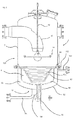
- the second outlet opening 16 is designed in the pipe section 10 such that a larger portion of this second outlet opening 16 is located to the right of the injector 12 that is the injection lance 12 and only a small portion to the left thereof. In this way, the pipe section within the housing and thus also its surface can be kept low.
- FIG. 3 shows an illustration of an evaporator according to the invention 1.
- This evaporator 1 in turn has a housing 2, and the pipe section 10, through which the gaseous medium, such as heated air, is introduced into the evaporator.
- the injection device 12 opens here into an annular nozzle 19, which injects the hydrogen peroxide with a plurality of nozzles extending in the circumferential direction.
- the heater 8 here has a line 62, which is designed as a tube spiral, and upwards, d. H. extended in the direction of the injector.
- the annular nozzles 19 can thus apply the sterilizing medium to the outer surface 62a of the conduit 62, i. Apply the inner surface of the truncated cone formed from the tube spiral and there the medium can evaporate.
- an upwardly tapered conical or frusto-conical arrangement of the coiled tubing is possible.
- it is achieved that the largest possible heating surface is present.
- a cylindrical arrangement of the coiled tubing is possible, in which case the annular nozzle 19 is advantageously arranged within the cylinder formed, or even a second annular nozzle is used to simultaneously impinge an outer surface of the cylinder.
- the flowable medium for example, then the line 62 and then passes into Fig. 3 from the bottom up.
- the flowable medium in an intermediate region 96 between the lower floor 92 and a higher floor 94 pass.
- the bottom portion 94 can be heated from the inside.
- the reference numeral 98 refers to the discharge line for discharging condensate from the bottom 90 of the evaporator 1.
- the reference numeral 108 denotes a further discharge line for removing excess disinfectant from the region between the line 62 and the upper floor 94. It is thereby achieved that no disinfectant accumulates in the heating device 8 and the bottom heating surface is completely available as an evaporation surface.
- the lower part of the evaporator i. H. including the conduit 62 and the two floors 92 and 94 via a connecting means, such as a flange 112 is disposed on the upper part 120 of the housing.
- Reference numeral 66 denotes baffles which guide the substance to the heater 8.
- the reference numeral 102 denotes a supply line for supplying the heating medium into the intermediate region 96 of the bottom 90.
- the reference numeral 68 denotes a temperature sensor which receives the surface temperature of the upper bottom 94 and thus one of the heating surfaces.
- Fig. 4 shows a further embodiment of an evaporator according to the invention.
- no continuation or no double bottom is provided below the line 62 but an electric heater.
- a multiplicity of heating cartridges 82 are arranged in a heatable bottom plate 80 and heat them. It would also be possible for the sterilization medium to fall onto this electrical heating plate 80 through an opening 63 formed by the configuration of the conical coil 62.
- the electric heating plate 80 is in turn separable via a flange of the bottom part 122, in which the line 62 is arranged.
- Fig. 5 shows a further embodiment of the device according to the invention.
- the steam-conducting pipe part 62 is designed so that H 2 O 2 dripping from the pipe part 62 is forcibly returned to the steam-carrying pipe part 62 again.
- a survey 132 may be provided, which transports the H 2 O 2 again in the direction of the line 62.
- This survey 132 can thereby appropriate design of the housing wall or be performed by a baffle.
- a design would be conceivable here, which is not designed as a pressure vessel.
Landscapes
- Health & Medical Sciences (AREA)
- Mechanical Engineering (AREA)
- Chemical & Material Sciences (AREA)
- Chemical Kinetics & Catalysis (AREA)
- Engineering & Computer Science (AREA)
- Epidemiology (AREA)
- General Chemical & Material Sciences (AREA)
- Life Sciences & Earth Sciences (AREA)
- Animal Behavior & Ethology (AREA)
- General Health & Medical Sciences (AREA)
- Public Health (AREA)
- Veterinary Medicine (AREA)
- Apparatus For Disinfection Or Sterilisation (AREA)
Abstract
Description
- Die vorliegende Erfindung bezieht sich auf einen Verdampfer zum Sterilisieren von Behältnissen und insbesondere von Kunststoffbehältnissen. Derartige Verdampfer sind aus dem Stand der Technik bekannt. Dabei wird üblicherweise Wasserstoffperoxid (H2O2) innerhalb des Verdampfers verdampft und gemeinsam mit einem zugeführten Luftstrom in ein zu sterilisierendes Behältnis geführt. Durch dieses Einführen des Gemisches in das Behältnis kann dessen Innenwandung gereinigt bzw. sterilisiert werden.
- Bei derartigen Verdampfern ist es jedoch erforderlich, die Menge des jeweils eingespritzten oder dem Behältnis zuzuführenden H2O2 präzise zu regulieren und dafür Sorge zu tragen, dass pro Behältnis jeweils die gleiche Menge an H2O2 zugeführt wird.
- Aus der
WO 2007/003313 sind ein Verfahren und eine Vorrichtung zum Überwachen eines Verdampfers bekannt. Bei diesem Verfahren wird auf einen erwärmten Heizkörper eine Flüssigkeit aufgebracht und verdampft und weiterhin ist seitlich an diesen Verdampfer eine Rohrleitung vorgesehen, durch welche hindurch erwärmte und sterile Luft von der Seite her in den Verdampfer bzw. dessen Gehäuse eingeleitet wird. Damit wird die Luftströmung hier senkrecht zu der Einspritzrichtung des Wasserstoffperoxids geführt. Diese Vorrichtung erlaubt eine effektive Zuführung von verdampften Wasserstoffperoxid in das Behältnis. Durch die Art der Zuführung ist jedoch eine exakte Regulierung der genauen Menge an Wasserstoffperoxid nur schwer möglich. - Die
DE 100 40 861 A1 beschreibt eine Vorrichtung zum Sterilisieren von Packungen mit Wasserstoffperoxid. Dabei wird das Wasserstoffperoxid in Längsrichtung an einer warmen Oberfläche vorbeigeführt. Auf diese Weise wird das mit dem Wasserstoffperoxid in nebelform versetzte Trägergas schon an dieser warmen Oberfläche verdampft. Auch bei dieser Vorrichtung ist eine genaue Regulierung der zugeführten Menge an Wasserstoffperoxid nur schwer möglich. - Aus der
EP 0 991 434 B1 ist ein multiples Flammpunkt-Verdampfungssystem bekannt. Auch wird in einen Verdampfer sowohl Wasserstoffperoxid als auch ein Trägergas eingeführt, wobei das Trägergas hier ebenfalls quer bezüglich der Einspritzrichtung des Wasserstoffperoxids fließt. - Die
US 5,879,648 beschreibt eine Vorrichtung zum Desinfizieren von Behältern. Dabei wird in einen Verdampfer sowohl Wasserstoffperoxid als auch über parallel verlaufende Öffnungen ein Gas eingeführt. Auch bei dieser Vorrichtung ist eine Feinregulierung des aus dem Verdampfer in die Behältnisse gelangenden Gemisches nur schwer möglich. - Aus der
DE 10 2007 034 205 ist ebenfalls ein Verdampfer bekannt, bei dem sowohl ein Sterilisationsmittel mittels einer elektrischen Heizeinrichtung verdampft wird. Derartige Heizeinrichtungen sind jedoch in der Herstellung und insbesondere auch im Betrieb relativ teuer. - Aus der
DE 10 2007 034 205.7 ist ein Verdampfer zum Sterilisieren von Kunststoffbehältnissen bekannt. Dieser Verdampfer verwendet eine Heizeinrichtung, auf welche eine Substanz eingespritzt wird, welche Wasserstoffperoxid enthält. Dabei erstreckt sich eine Einspritzeinrichtung in der im Wesentlichen vertikalen Richtung innerhalb dieses Verdampfers. Der Gegenstand derDE 10 2007 034 205.7 wird durch Bezugnahme voll umfänglich auf den Gegenstand der vorliegenden Patentanmeldung gemacht. - Der vorliegenden Erfindung liegt daher die Aufgabe zugrunde, einen Verdampfer zu schaffen, der insbesondere im Betrieb kostengünstig ist. Daneben soll ein Verdampfer zu Verfügung gestellt werden. der eine sehr genaue Regulierung des aus diesem austretenden Wasserstoffperoxid-Gasgemisches erlaubt.
- Dies wird erfindungsgemäß durch einen Verdampfer nach Anspruch 1 sowie ein Verfahren zum Sterilisieren von Behältnissen nach Anspruch 16 erreicht. Vorteilhafte Ausführungsformen und Weiterbildungen sind Gegenstand der Unteransprüche.
- Der erfindungsgemäße Verdampfer zum Sterilisieren von Behältnissen weist ein Gehäuse auf, und eine erste in dem Gehäuse angeordnete Öffnung, um dem Gehäuse ein gasförmiges Medium zuzuführen. Weiterhin ist eine Einspritzeinrichtung vorgesehen, um in das Gehäuse eine Substanz einzuspritzen, welche Wasserstoffperoxid enthält. Weiterhin ist innerhalb des Gehäuses eine Heizeinrichtung angeordnet, um das Wasserstoffperoxid zu verdampfen. Daneben ist eine zweite in dem Gehäuse angeordnete Öffnung vorgesehen, um ein Gemisch aus dem gasförmigen Medium und dem verdampften Wasserstoffperoxid aus dem Gehäuse abzuführen.
- Erfindungsgemäß weist die Heizeinrichtung eine von einem fließfähigen Medium durchströmbare Leitung auf, wobei diese Leitung zum Erwärmen der Heizeinrichtung dient und von der Substanz - insbesondere unmittelbar - beaufschlagbar ist.
- Es werden daher Weiterentwicklungen, insbesondere hinsichtlich der Heiz- oder Erwärmungseinrichtung vorgeschlagen. Im Stand der Technik werden für die Heizeinrichtung üblicherweise hochverdichtete Heizpatronen verwendet. Im Rahmen der vorliegenden Erfindung wird vorgeschlagen, die Erwärmung mittels eines fließfähigen Mediums, insbesondere Dampf, zu erreichen. Dabei wird das zugeführte fließfähige Medium eine Verdampfungseinrichtung erhitzen. Auf diese Verdampfungs- bzw. Heizeinrichtung wird dann das flüssige Sterilisationsmedium, insbesondere H2O2 aufgebracht und dabei verdampft. Der entstehende H2O2 Dampf wird dann durch die ebenfalls eingeleitete Luft aufgenommen und aus dem Verdampfer abtransportiert. Bei dem fließfähigen Medium handelt es sich insbesondere um Dampf, es könnte jedoch auch ein anderes Medium, wie etwa Öl vorgesehen sein.
- Die Vorteile eines derart mit Fließmittel betätigten Verdampfers liegen vor allem in der günstigeren Energie sowie der wesentlich einfacheren Regelung dieses Verdampfers und ferner auch darin, dass der Verdampfer nicht überhitzen kann. Unter einer - insbesondere unmittelbar - beaufschlagbaren Leitung wird verstanden, dass das Medium direkt an die Leitung, insbesondere eine Außenoberfläche der Leitung gelangen kann. Damit erwärmt die Leitung nicht eine Heizfläche, an der die Substanz verdampfen kann, sondern die Leitung, insbesondere deren Außenoberfläche bildet insbesondere selbst eine Heizfläche aus.
- Bei einer weiteren vorteilhaften Ausführungsform weist die Einspritzeinrichtung eine Düse auf, welche das fließfähige Medium auf eine Außenoberfläche der Leitung aufbringt. Diese Düse kann dabei das Sterilisationsmedium auch besonders vorteilhaft zerstäuben, um auf diese Weise den Verdampfungsprozess effizienter zu gestalten. Bei einer weiteren vorteilhaften Ausführungsform ist die Leitung wenigstens abschnittsweise spiralförmig ausgebildet. Durch diese spiralförmige Ausbildung kann die Oberfläche, auf welche das Sterilisationsmedium aufgebracht werden kann, vergrößert und auf diese Weise die Effizienz gesteigert werden.
- Bei einer weiteren vorteilhaften Ausführungsform bildet die Leitung wenigstens abschnittsweise eine kegelförmige bzw. kegelstumpfförmige Oberfläche auf. Dabei könnten beispielsweise die Rohrleitungen spiralförmig gewunden werden und beispielsweise von oben nach unten einen sich verringerten Querschnitt aufweisen. Durch diese kegelförmige Oberfläche ist es weiter möglich, die Oberfläche der gesamten Heizeinrichtung zu vergrößern. Besonders vorteilhaft ist eine spiralförmig sich nach unten verringernde Anordnung der besagten Leitung bzw. eine sich verringernde Wendel vorgesehen. Vorzugsweise liegen die einzelnen Wendel der Leitung aneinander, sodass die Substanz keine Zwischenräume dieser Wendel passieren kann. Damit ist vorteilhaft hier die Leitung als gerolltes oder gewickeltes Rohr ausgebildet. Es wäre jedoch auch möglich, dass die Leitung dadurch ausgebildet ist, dass an einer Außenoberfläche eines Grundkörpers ein spiralförmiger Steg angeordnet ist und eine zweite Wand auf diesem Steg aufliegt, sodass sich insbesondere ein spiralförmiger Kanal ergibt.
- Bei einer weiteren vorteilhaften Ausführungsform ist ein weiterer Bestandteil des Verdampfers erwärmbar. So könnte beispielsweise die Vorrichtung unterhalb der Leitung einen beheizbaren Abschnitt aufweisen. Dieser beheizbare Abschnitt könnte dabei elektrisch geheizt werden, beispielsweise mit Heizpatronen, aber auch durch die Verwendung eines fließfähigen Mediums.
- Bei einer weiteren vorteilhaften Ausführungsform ist wenigstens ein weiterer Bestandteil des Gehäuses auch durch ein fließfähiges Medium erwärmbar. So könnte beispielsweise die Vorrichtung einen doppelwandigen Boden aufweisen, und ein fließfähiges erwärmendes Medium könnte im Zwischenraum zwischen diesen beiden Böden eingeführt werden. So wäre es beispielsweise möglich, dass der Verdampfer mit einem doppelwandigen Klöpperboden ausgeführt ist und zusätzlich die oben beschriebene konische Rohrwendel im Inneren des Verdampfers vorgesehen ist. Eine Versorgung mit dem fließfähigen Medium, insbesondere eine Dampfversorgung wird dabei vorteilhaft mit einer gemeinsamen Zuleitung bewerkstelligt. Diese Zuleitung kann sich dann in zwei Flansche aufzweigen, wobei es möglich ist, dass das Kondensat der Wendel direkt in den doppelwandigen Klöpperboden geleitet und dort durch einen Kondensatabscheider ausgeleitet wird.
- Der Hauptteil der zur Verdampfung des H2O2 benötigten Energie wird dabei vorteilhaft durch die Leitung zugeführt. Der Vorteil dieser Leitung liegt einerseits in der großen Übertragungsfläche, welche dieses gewickelte Rohr bietet und daneben auch in der wesentlich geringeren Wandstärke gegenüber dem Boden bzw. Klöpperboden. Auf diese Weise kann im Verhältnis zu dem Klöpperboden wesentlich mehr Energie übertragen werden. Hierbei wäre es auch möglich, eine Ausführungsform zu schaffen, welche ohne die besagte innere Wendel auskommt, diese wäre jedoch in ihren Abmessungen erheblich größer.
- In einer weiteren Ausführungsform wäre es auch möglich, die Begleitheizung deutlich zu reduzieren und diese Begleitheizung mit einer anderen Energieform vorzugsweise elektrischer Energie, zu versorgen. Da der Hauptteil der benötigten Energie über die Dampfheizung zugeführt wird, bleiben auch hier die Verluste gering. Auf diese Weise wäre eine Bauform denkbar, die ohne Druckbehälter auskommt, was wiederum die Herstellungskosten verringern könnte.
- Bei einer weiteren vorteilhaften Ausführungsform ist die Einspritzeinrichtung als Ringdüse ausgebildet. So könnten beispielsweise eine oder auch mehrere Düsen vorgesehen sein, wobei vorteilhaft über die besagte Ringdüse das H2O2 direkt auf den dampfführenden Leitungsteil aufgebracht und dort verdampft wird. Wie oben erwähnt, kann dabei zusätzlich auch das Gehäuse oder ein wesentlicher Teil des Gehäuses des Verdampfers so ausgeführt werden, dass es erwärmt werden kann. Der Vorteil dieses erwärmten Gehäuses bzw. Gehäuseteils liegt darin, dass auch von den Leitungen abtropfendes H2O2 noch verdampft wird.
- Vorteilhaft ist unterhalb der Leitung ein doppelwandiger Boden vorgesehen, wobei zwischen den Wänden dieses Bodens ein fließfähiges Medium führbar ist. Auf diese Weise kann, wie oben erwähnt, auch im Bereich des Bodens des Verdampfers noch ein zusätzliches Verdampfen des Sterilisationsmediums durchgeführt werden. Vorteilhaft schließt sich dabei der doppelwandige Boden in einer Strömungsrichtung des fließfähigen Mediums an die Leitung an. Auf diese Weise kann das fließfähige Medium bzw. der Dampf, der bereits die Leitung erwärmt hat im Nachgang auch noch den besagtem Boden erwärmen.
- Vorteilhaft erstreckt sich eine Längsrichtung der Einspritzeinrichtung in einer vertikalen Richtung und an die erste Öffnung schließt sich ein Rohrabschnitt an, der sich wenigstens abschnittsweise in der Längsrichtung der Einspritzeinrichtung erstreckt, wobei die Einspritzeinrichtung wenigstens abschnittsweise innerhalb dieses Rohrabschnitts verläuft.
- Bei der Einspritzeinrichtung handelt es sich bevorzugt um eine lanzenförmige Einspritzeinrichtung und die Längsrichtung der Einspritzeinrichtung ist durch die Längsrichtung dieser Lanze definiert. Bevorzugt handelt es sich bei der eingespritzten Substanz um Wasserstoffperoxid. Dieses kann dabei sowohl in flüssiger Form als auch in nebelartiger Konsistenz eingespritzt werden. Es wären jedoch auch andere als lanzenförmige Einspritzeinrichtungen denkbar. Bei anders gestalteten Einspritzeinrichtungen ist deren Längsrichtung auch durch die Strömungsrichtung des H2O2 beim Austritt durch eine Düse der Einspritzeinrichtung definiert.
- Durch die Anordnung der Einspritzeinrichtung innerhalb des Rohrabschnitts kann weiterhin erreicht werden, dass das aus dem Rohrabschnitt austretende Gas im Wesentlichen gleichförmig die Einspritzeinrichtung umgibt. Auf diese Weise kann ebenfalls eine gleichmäßige Anreicherung des Gases mit dem Wasserstoffperoxid bewirkt werden. Bei einer vorteilhaften Ausführungsform erstreckt sich der Rohrabschnitt innerhalb des Gehäuses wenigstens abschnittsweise in der Längsrichtung der Einspritzeinrichtung. Dies bedeutet, dass sich der Rohrabschnitt ausgehend von der ersten Öffnung nach innen und in der Längsrichtung der Einspritzeinrichtung erstreckt.
- Weiterhin weist bevorzugt der Rohrabschnitt eine erste Austrittsöffnung auf, die derart angeordnet ist, dass das gasförmige Medium in einer zu der Längsrichtung parallelen Richtung aus dem Rohrabschnitt austritt. Dies bedeutet, dass es sich bei demjenigen Rohrabschnitt, der parallel zu der Längsrichtung der Einspritzrichtung ist, um einen Endabschnitt dieses Rohrabschnitts handelt.
- Bei einer weiteren vorteilhaften Ausführungsform weist der Rohrabschnitt eine zweite Austrittsöffnung auf, die zwischen der in dem Gehäuse angeordneten Öffnung (des Gehäuses) und der ersten Austrittsöffnung vorgesehen ist. Auf diese Weise kann ein Teilstrom auch in einer anderen Richtung als der Längsrichtung der Einspritzeinrichtung ausgeführt werden.
- Vorzugsweise ist diese zweite Austrittsöffnung derart angeordnet, dass das durch diese Austrittsöffnung austretende gasförmige Medium unmittelbar in Richtung der zweiten Öffnung (des Gehäuses) strömt. Unter unmittelbar wird dabei verstanden, dass die Strömung ohne umgelenkt zu werden, in Richtung der zweiten Öffnung strömt. Vorzugsweise weist das Gehäuse abgesehen von der ersten Öffnung und der zweiten Öffnung keine Öffnung auf, durch welche hindurch ein gasförmiges Medium in das Gehäuse hinein oder aus dem Gehäuse heraustreten kann.
- Vorzugsweise sind die erste Öffnung in dem Gehäuse und die zweite Öffnung in dem Gehäuse auf gegenüberliegenden Seiten beispielsweise auf gegenüberliegenden Seiten in der Ummantelung des Gehäuses oder auch auf gegenüberliegenden Seiten in Längsrichtung der Einspritzeinrichtung angeordnet.
- Vorteilhaft ist die erste Öffnung in einer Umfangswand des Gehäuses angeordnet. Bei einer weiteren vorteilhaften Ausführungsform weist der Rohrabschnitt einen gekrümmten Bereich auf, wobei dieser gekrümmte Bereich in einer Ausführungsform im Inneren des Gehäuses verläuft.
- Bevorzugt ist bei dieser Ausführungsform die zweite Austrittsöffnung des Rohrabschnitts in dem gekrümmten Bereich desselben angeordnet.
- Bei einer weiteren vorteilhaften Ausführungsform weist die Einspritzeinrichtung eine Austrittsdüse für das Wasserstoffperoxid auf und diese Austrittsdüse ist unterhalb der ersten Austrittsöffnung des Rohrabschnitts angeordnet. Dies bedeutet, dass der Rohrabschnitt und die Austrittsdüse nicht auf gleiche Höhe abschließen sondern die Austrittsdüse näher an der Heizeinrichtung ist als die Austrittsöffnung des Rohrabschnitts. Bei einer weiteren Ausführungsform sind an dem Rohrabschnitt Luftführungseinrichtungen vorgesehen, welche einen Teil der Luftströmung an eine Innenwandung des Verdampfers richten. Bevorzugt weist der Rohrabschnitt ein Innenrohr auf, welches die Einspritzeinrichtung konzentrisch umgibt und in wenigstens einem Bereich dieses Innenrohrs ist ein Außenrohr vorgesehen, wobei zwischen diesem Außenrohr und dem Innenrohr die Luftführungseinrichtungen vorgesehen sind. In diesem Falle handelt es sich bei dem Innenrohr um den erfindungsgemäßen Rohrabschnitt.
- Bei einer weiteren vorteilhaften Ausführungsform sind die Einspritzeinrichtung und der Rohrabschnitt wenigstens abschnittsweise im Wesentlichen konzentrisch zueinander. Weiterhin ist besonders bevorzugt der Verdampfer bzw. dessen Gehäuse im Wesentlichen rotationssymmetrisch bezüglich einer Zentralachse ausgebildet.
- Bei einer weiteren vorteilhaften Ausführungsform ist die Einspritzeinrichtung drehbar gegenüber dem Gehäuse angeordnet. Genauer gesagt ist die Einspritzeinrichtung und bevorzugt auch der Rohrabschnitt stationär und das Gehäuse dreht sich diesem gegenüber. Es wäre jedoch auch möglich, die Einspritzeinrichtung fest an dem Gehäuse und dieses stationär anzuordnen und gegenüber dem Gehäuse einen Auslassstutzen zum Abführen des Gemisches drehbar anzuordnen.
- Die vorliegende Erfindung ist weiterhin auf eine Anordnung zum Sterilisieren von Behältnissen und insbesondere von Kunststoffbehältnissen gerichtet, die wenigstens einen Verdampfer der oben beschriebenen Art aufweist. Bevorzugt weist diese Anordnung eine Erwärmungseinrichtung zum Erwärmen des gasförmigen Mediums auf. Genauer gesagt wird das gasförmige Medium erwärmt, bevor es in den Verdampfer eintritt.
- Die vorliegende Erfindung ist weiterhin auf ein Verfahren zum Sterilisieren von Behältnissen gerichtet, wobei in einem Verdampfer ein gasförmiges Medium eingeführt wird und mittels einer Einspritzeinrichtung eine Substanz eingespritzt wird, welche vorteilhaft Wasserstoffperoxid enthält. Dabei wird diese Substanz an einer Heizeinrichtung verdampft und über eine zweite in einem Gehäuse angeordnete Öffnung das entstehende Gemisch aus dem gasförmigen Medium und der verdampften Substanz abgeführt. Vorteilhaft wird die Heizeinrichtung mittels eines fließfähigen Mediums erwärmt und die Substanz trifft bevorzugt unmittelbar auf eine von dem fließfähigen Medium erwärmte Leitung auf.
- Es wird daher auch verfahrensseitig vorgeschlagen, die Erwärmung nicht oder nicht nur über eine elektrische Heizeinrichtung durchzuführen, sondern insbesondere auch ein fließfähiges Medium, wie beispielsweise Dampf zu verwenden.
- Die vorliegende Erfindung eignet sich insbesondere beim Betrieb von Anlagen zur Sterilisation von Behältnissen, die sehr hohen hygienischen Anforderungen genügen müssen. Insbesondere können durch die Verwendung der Erfindung die Anforderungen der US Behörde FDA (Food and Drug Administration) leichter erfüllt werden.
- Weitere Vorteile und Ausführungsformen ergeben sich aus den beigefügten Zeichnungen:
- Darin zeigen:
- Fig. 1
- eine perspektivische Ansicht eines Verdampfers nach dem Stand der Technik;
- Fig. 2
- eine Querschnittsdarstellung des Verdampfers aus
Fig. 1 ; - Fig. 3
- eine Querschnittsdarstellung eines erfindungsgemäßen Verdampfer;
- Fig. 4
- einen Verdampfer in einer weiteren Ausführungsform; und
- Fig. 5
- einen Verdampfer in einer weiteren Ausführungsform.
-
Fig. 1 zeigt einen Verdampfer 1. Dieser Verdampfer weist ein Gehäuse 2 mit einer umlaufenden Wandung 2a und einem Deckelabschnitt 3 auf, der durch einen mit Schrauben 13 aufgeschraubten Deckel 7 verschlossen ist. Nach unten hin ist das Gehäuse durch eine Heizeinrichtung 8 bzw. eine Heizfläche 8a abgeschlossen. Die Ebene dieser Heizfläche steht senkrecht zur Figurenebene. Das Bezugszeichen 12 bezieht sich auf eine Einspritzeinrichtung, deren Längsrichtung sich senkrecht zu der Ebene der Heizfläche 8a erstreckt. Durch diese Einspritzeinrichtung 12, genauer gesagt einen Kanal 12a im Innenraum der Einspritzeinrichtung 12 wird Wasserstoffperoxid in das Gehäuse 2 und in Richtung der Heizeinrichtung 8 geführt. Bei der inFig. 1 gezeigten Ausführungsform ist die Einspritzeinrichtung 12 konzentrisch mit der Umfangswand 2a angeordnet. Am unteren Ende weist die Einspritzeinrichtung 12 eine Düse 18 auf, über die Wasserstoffperoxid austreten kann und auf die Heizfläche 8a gespritzt wird. - Das Bezugszeichen 24 bezieht sich auf einen Temperatursensor zum Ermitteln der Temperatur der Heizeinrichtung 8. Oberhalb der Heizeinrichtung 8 ist ein Trägerring 15 vorgesehen, auf dem wiederum das Gehäuse 2 abgestützt ist. Bevorzugt ist dieser Trägerring 15 aus einem Material hergestellt, welches einen geringen Wärmeleistungsquotienten aufweist, damit sich über die von der Heizeinrichtung 8 abgegebene Wärme das Gehäuse 2 nicht oder nicht wesentlich erwärmt.
- Das Bezugszeichen 11 bezieht sich auf eine erste Öffnung (Eintrittsöffnung) in dem Gehäuse 2, durch welche hindurch das gasförmige Medium in das Innere des Gehäuses 2 gelangen kann. Die erste Öffnung 11 ist dabei in einem Flansch 17 angeordnet, der an der Gehäusewandung 2a befestigt ist. Im Inneren des Gehäuses 2 schließt sich an die erste Öffnung 11 ein Rohrabschnitt 10 an. Dieser Rohrabschnitt 10 weist einen gekrümmten Bereich 10a und eine erste Austrittsöffnung 14, durch welche hindurch das gasförmige Medium austreten kann, auf. Damit erfolgt die Strömungsführung der erwärmten Luft abschnittsweise parallel zu der Wasserstoffperoxidzufuhr über die Einspritzeinrichtung 12. Zu diesem Zweck wird die durch die erste Öffnung 11 einströmende Luft in den gekrümmten Abschnitt 10a umgelenkt.
- Das Bezugszeichen 16 bezieht sich auf eine zweite Austrittsöffnung in dem Rohrabschnitt 10. Durch diese Öffnung tritt einerseits die Einspritzeinrichtung 12 hindurch. Auf diese Weise kann die Einspritzeinrichtung wenigstens teilweise innerhalb des Rohrabschnitts 10 geführt werden. Daneben kann durch die zweite Austrittsöffnung 6 auch ein Anteil des gasförmigen Mediums aus dem Rohrabschnitt austreten und in Richtung einer Austrittsöffnung 4 gelangen. Über die Austrittsöffnung 4, die ebenfalls mittels eines Flansches 5 an der Gehäusewandung 2a angeordnet ist, kann das in dem Verdampfer entstehende Gasgemisch abgeführt und anschließend den zu sterilisierenden Behältnissen zugeführt werden.
-
Fig. 2 zeigt eine Querschnittsdarstellung eines Verdampfers ausFigur 1 . Man erkennt, dass die Düse 18 der Einspritzeinrichtung 12 wesentlich weiter in das Innere des Gehäuses hineinragt bzw. wesentlich näher an der Heizeinrichtung 8 angeordnet ist als die erste Austrittsöffnung 14 des Rohrabschnitts 10. In dem Endabschnitt 19 des Rohrabschnitts 10 wird das hindurch tretende gasförmige Medium nicht genau in der Längsrichtung geführt sondern in einem gewissen Winkel hierzu geneigt. Auf diese Weise wird erreicht, dass durch entsprechende Reflexionen des gasförmigen Mediums an der Heizeinrichtung eine besonders vorteilhafte Durchmischung mit dem verdampfenden Wasserstoffperoxid auftritt. Genauer gesagt wird das durch den Rohrabschnitt 10 hindurch tretende gasförmige Medium wieder geringfügig zurück in Richtung der ersten Öffnung 4 geführt. Das Bezugszeichen 22 bezieht sich auf einen Anschluss für eine Wasserstoffperoxidzuleitung. Das Bezugszeichen 25 bezieht sich auf eine Zuleitung für ein Kühlmedium für die Heizeinrichtung 8. - Man erkennt, dass die zweite Austrittsöffnung 16 in dem Rohrabschnitt 10 derart ausgelegt ist, dass sich ein größerer Abschnitt dieser zweiten Austrittsöffnung 16 rechts bezüglich der Einspritzeinrichtung 12 das heißt der Einspritzlanze 12 befindet und nur ein kleiner Abschnitt links hiervon. Auf diese Weise kann der Rohrabschnitt innerhalb des Gehäuses und damit auch seine Oberfläche gering gehalten werden.
-
Fig. 3 zeigt eine Darstellung eines erfindungsgemäßen Verdampfers 1. Dieser Verdampfer 1 weist dabei wiederum ein Gehäuse 2 auf, sowie den Rohrabschnitt 10, über den das gasförmige Medium, wie beispielsweise erwärmte Luft, in den Verdampfer eingeführt wird. Die Einspritzeinrichtung 12 mündet hier in eine Ringdüse 19, welche das Wasserstoffperoxid mit einer Vielzahl von in Umfangsrichtung verlaufenden Düsen einspritzt. - Die Heizeinrichtung 8 weist hier eine Leitung 62 auf, welche als Rohrwendel ausgeführt ist, und sich nach oben hin, d. h. in Richtung der Einspritzeinrichtung erweitert. Die Ringdüsen 19 können damit das Sterilisationsmedium auf die Außenoberfläche 62a der Leitung 62, d.h. die Innenoberfläche des aus der Rohrwendel gebildeten Kegelstumpfes aufbringen und dort kann das Medium verdampfen. Alternativ ist auch eine sich nach oben hin verjüngende kegel- oder kegelstumpfförmige Anordnung der Rohrwendel möglich. Auch in dieser Ausführungsform wird erreicht, dass eine möglichst große Heizoberfläche vorliegt. Weiterhin ist eine zylindrische Anordnung der Rohrwendel möglich, wobei dann die Ringdüse 19 vorteilhaft innerhalb des gebildeten Zylinders angeordnet ist oder gar eine zweite Ringdüse zur gleichzeitigen Beaufschlagung einer Außenoberfläche des Zylinders eingesetzt wird.
- Über eine nicht gezeigte Zuleitung wird das fließfähige Medium beispielsweise dann der Leitung 62 zugeführt und gelangt anschließend in
Fig. 3 von unten nach oben. Am Ende der Leitung 62 kann das fließfähige Medium in einem Zwischenbereich 96 zwischen dem unteren Boden 92 und einem höheren Boden 94 gelangen. Auf diese Weise kann auch insbesondere der Bodenabschnitt 94 von innen erwärmt werden. - Das Bezugszeichen 98 bezieht sich auf die Abführleitung zum Abführen von Kondensat aus dem Boden 90 des Verdampfers 1. Das Bezugszeichen 108 kennzeichnet eine weitere Abführleitung um nicht überschüssiges Desinfektionsmittel aus dem Bereich zwischen der Leitung 62 und dem oberen Boden 94 abzuführen. Dadurch wird erreicht, dass sich in der Heizeinrichtung 8 kein Desinfektionsmittel anstaut und die Bodenheizfläche vollständig als Verdampfungsfläche zur Verfügung steht.
- Man erkennt, dass der untere Teil des Verdampfers, d. h. einschließlich der Leitung 62 und der beiden Böden 92 und 94 über eine Verbindungseinrichtung, wie einen Flansch 112 an dem oberen Teil 120 des Gehäuses angeordnet ist. Das Bezugszeichen 66 kennzeichnet Leitbleche welche die Substanz zu der Heizeinrichtung 8 leiten. Das Bezugszeichen 102 kennzeichnet eine Zuführleitung zum Zuführen des Heizmediums in den Zwischenbereich 96 des Bodens 90. Das Bezugszeichen 68 kennzeichnet einen Temperatursensor, der die Oberflächentemperatur des oberen Bodens 94 und somit einer der Heizflächen aufnimmt.
-
Fig. 4 zeigt eine weitere Ausführungsform eines erfindungsgemäßen Verdampfers. Bei dieser Ausführungsform ist unterhalb der Leitung 62 keine Weiterführung bzw. kein Doppelboden vorgesehen sondern eine elektrische Heizung. Zu diesem Zweck ist eine Vielzahl von Heizpatronen 82 in einer beheizbaren Bodenplatte 80 angeordnet und erwärmt diese. Es wäre auch möglich, dass das Sterilisationsmedium durch eine Öffnung 63, welche durch die Ausgestaltung der kegelförmigen Wendel 62 ausgebildet wird, auf diese elektrische Heizplatte 80 fällt. Die elektrische Heizplatte 80 ist dabei wiederum über einen Flansch von dem Bodenteil 122, in dem auch die Leitung 62 angeordnet ist, trennbar. -
Fig. 5 zeigt eine weitere Ausführungsform der erfindungsgemäßen Vorrichtung. Bei dieser Ausführungsform ist keine weitere Zusatzheizung bzw. Begleitheizung vorgesehen. Bei dieser Ausführungsform wird der dampfführende Leitungsteil 62 so ausgeführt, dass vom Leitungsteil 62 abtropfendes H2O2 zwangsweise wieder zu dem dampfführenden Leitungsteil 62 zurückgeführt wird. So kann beispielsweise eine Erhebung 132 vorgesehen sein, welche das H2O2 wieder in Richtung der Leitung 62 transportiert. Diese Erhebung 132 kann dabei durch entsprechende Gestaltung der Gehäusewand oder auch durch ein Leitblech ausgeführt sein. Daneben wäre hier jedoch auch eine Bauform denkbar, die nicht als Druckbehälter ausgeführt ist. - Die Anmelderin behält sich vor, sämtliche in den Anmeldungsunterlagen offenbarten Merkmale als erfindungswesentlich zu beanspruchen, sofern sie einzeln oder in Kombination gegenüber dem Stand der Technik neu sind.
-
- 1
- Verdampfer
- 2
- Gehäuse
- 2a
- umlaufende Wandung
- 3
- Deckelabschnitt des Gehäuses
- 4
- zweite (Austritts-) Öffnung in dem Gehäuse 2
- 5
- Flansch
- 7
- aufgeschraubter Deckel
- 8
- Heizeinrichtung
- 8a
- Heizfläche
- 10
- Rohrabschnitt
- 10a
- gekrümmter Bereich
- 11
- erste (Eintritts-) Öffnung in dem Gehäuse 2
- 12
- Einspritzeinrichtung
- 12a
- Kanal der Einspritzeinrichtung
- 13
- Schraube
- 14
- erste Austrittsöffnung in dem Rohrabschnitt 10
- 15
- Trägerring
- 16
- zweite Austrittsöffnung in dem Rohrabschnitt 10
- 17
- Flansch
- 18
- Düse
- 19
- Ringdüse
- 22
- Anschluss
- 24
- Temperatursensor
- 25
- Zuleitung
- 62
- Leitung
- 62a
- Außenoberfläche
- 63
- Öffnung
- 66
- Leitblech
- 68
- Temperatursensor
- 80
- beheizbare Bodenplatte
- 82
- Heizpatrone
- 90
- Boden
- 92
- unterer Boden
- 94
- oberer Boden
- 96
- Zwischenbereich
- 98
- Abführleitung
- 102
- Zuführleitung
- 108
- weitere Abführleitung
- 112
- Flansch
- 120
- oberer Teil des Gehäuses
- 122
- Bodenteil
- 132
- Erhebung
- L
- Längsrichtung
Claims (11)
- Verdampfer (1) zum Sterilisieren von Behältnissen mit einem Gehäuse (2), mit einer ersten in dem Gehäuse (2) angeordneten Öffnung (11), um dem Gehäuse (2) ein gasförmiges Medium zuzuführen, mit einer Einspritzeinrichtung (12), um in das Gehäuse (2) eine Substanz einzuspritzen, welche Wasserstoffperoxid (H2O2) enthält, mit einer innerhalb des Gehäuses (2) angeordneten Heizeinrichtung (8) zum Verdampfen des Wasserstoffperoxids und mit einer zweiten in dem Gehäuse (2) angeordneten Öffnung (4), um ein Gemisch aus dem gasförmigen Medium und dem verdampften Wasserstoffperoxid aus dem Gehäuse (2) abzuführen,
dadurch gekennzeichnet, dass
die Heizeinrichtung (8) eine von einem fließfähigen Medium durchströmbare Leitung (62) aufweist, wobei diese Leitung (62) zum Erwärmen der Heizeinrichtung (8) dient und von der Substanz beaufschlagbar ist. - Verdampfer (1) nach Anspruch 1,
dadurch gekennzeichnet, dass
die Einspritzeinrichtung (12) eine Düse (18, 19) aufweist, welche das fließfähige Medium auf eine Außenoberfläche der Leitung aufbringt. - Verdampfer (1) nach wenigstens einem der vorangegangenen Ansprüche,
dadurch gekennzeichnet, dass
die Leitung (62) wenigstens abschnittsweise spiralförmig ausgebildet ist. - Verdampfer (1) nach wenigstens einem der vorangegangenen Ansprüche,
dadurch gekennzeichnet, dass
die Leitung (62) wenigstens abschnittsweise eine kegelförmige Oberfläche (62a) ausbildet. - Verdampfer (1) nach wenigstens einem der vorangegangenen Ansprüche,
dadurch gekennzeichnet, dass
wenigstens ein weiterer Bestandteil des Gehäuses (2) durch ein fließfähiges Medium erwärmbar ist. - Verdampfer (1) nach wenigstens einem der vorangegangenen Ansprüche,
dadurch gekennzeichnet, dass
die Vorrichtung (1) unterhalb der Leitung (62) einen beheizbaren Abschnitt (80) aufweist. - Verdampfer (1) nach wenigstens einem der vorangegangenen Ansprüche,
dadurch gekennzeichnet, dass
die Einspritzeinrichtung (12) als Ringdüse (19) ausgebildet ist. - Verdampfer (1) nach wenigstens einem der vorangegangenen Ansprüche,
dadurch gekennzeichnet, dass
unterhalb der Leitung (62) ein doppelwandiger Boden (90) vorgesehen ist, wobei zwischen den Wänden (92, 94) dieses Bodens ein fließfähiges Medium führbar ist - Verdampfer (1) nach Anspruch 8,
dadurch gekennzeichnet, dass
sich der doppelwandige Boden (90) in einer Strömungsrichtung des fließfähigen Mediums an die Leitung (62) anschließt. - Verdampfer (1) nach wenigstens einem der vorangegangenen Ansprüche,
dadurch gekennzeichnet, dass
die Heizeinrichtung (8) eine Öffnung (63) ausbildet, welche unterhalb der Einspritzeinrichtung (12) angeordnet ist - Verfahren zum Sterilisieren von Behältnissen, wobei in einen Verdampfer (1) ein gasförmiges Medium eingeführt wird und mittels einer Einspritzeinrichtung (12) eine Substanz eingespritzt wird, welche Wasserstoffperoxid (H2O2) enthält und wobei diese Substanz an einer Heizeinrichtung (8) verdampft wird und über eine zweite in dem Gehäuse (2) angeordnete Öffnung (4) das entstehende Gemisch aus dem gasförmigen Medium und der verdampften Substanz abgeführt wird,
dadurch gekennzeichnet, dass
die Heizeinrichtung (8) mittels eines fließfähigen Mediums erwärmt wird.
Applications Claiming Priority (1)
| Application Number | Priority Date | Filing Date | Title |
|---|---|---|---|
| DE102010027076A DE102010027076A1 (de) | 2010-07-13 | 2010-07-13 | Verdampfer zum Sterilisieren von Kunststoffbehältnissen |
Publications (2)
| Publication Number | Publication Date |
|---|---|
| EP2407181A1 true EP2407181A1 (de) | 2012-01-18 |
| EP2407181B1 EP2407181B1 (de) | 2017-05-17 |
Family
ID=44514184
Family Applications (1)
| Application Number | Title | Priority Date | Filing Date |
|---|---|---|---|
| EP11172637.8A Active EP2407181B1 (de) | 2010-07-13 | 2011-07-05 | Verdampfer zum Sterilisieren von Kunststoffbehältnissen |
Country Status (3)
| Country | Link |
|---|---|
| EP (1) | EP2407181B1 (de) |
| CN (1) | CN102327629B (de) |
| DE (1) | DE102010027076A1 (de) |
Cited By (8)
| Publication number | Priority date | Publication date | Assignee | Title |
|---|---|---|---|---|
| CN107161934A (zh) * | 2017-07-14 | 2017-09-15 | 韩珠龙 | 一种新型洗发水恒温灌装装置 |
| WO2018060422A3 (de) * | 2016-09-29 | 2018-05-31 | Krones Ag | Vorrichtung zum verdampfen eines flüssigen mediums in einer füllproduktabfüllanlage |
| CN110755660A (zh) * | 2019-10-09 | 2020-02-07 | 江苏新美星包装机械股份有限公司 | 一种汽化装置 |
| CN115155079A (zh) * | 2021-04-02 | 2022-10-11 | 楚天科技股份有限公司 | 一种过氧化氢蒸发装置 |
| CN115177962A (zh) * | 2021-04-02 | 2022-10-14 | 楚天科技股份有限公司 | 一种降低能耗的集中式过氧化氢蒸发装置 |
| WO2023237916A1 (en) * | 2022-06-06 | 2023-12-14 | Sofranko Jan | The device and method for the generation, control, and application of hydrogen peroxide vapor dose |
| EP4650022A1 (de) | 2024-05-16 | 2025-11-19 | GASTI Verpackungsmaschinen GmbH | Vorrichtung zum verdampfen einer flüssigkeit |
| EP4650023A1 (de) | 2024-05-16 | 2025-11-19 | GASTI Verpackungsmaschinen GmbH | Vorrichtung zum verdampfen einer flüssigkeit |
Families Citing this family (4)
| Publication number | Priority date | Publication date | Assignee | Title |
|---|---|---|---|---|
| DE102011056438A1 (de) | 2011-12-14 | 2013-06-20 | Krones Ag | Verdampfervorrichtung, Getränkeabfüllanlage und/oder Getränkebehälterherstellanlage, Verfahren zum Betreiben einer Verdampfervorrichtung und Verwendung einer Sterilisationsgemisch-Abführeinrichtung |
| DE102011056449B4 (de) | 2011-12-15 | 2023-05-11 | Krones Ag | Verdampfervorrichtung zum Sterilisieren von Behältern, Getränkeabfüllanlage und/oder Getränkebehälterherstellanlage |
| KR20240133776A (ko) | 2017-03-27 | 2024-09-04 | 리제너론 파아마슈티컬스, 인크. | 살균 방법 |
| DE102020123389A1 (de) * | 2020-09-08 | 2022-03-10 | Ampack Gmbh | Verdampfervorrichtung, insbesondere Sterilisationsverdampfervorrichtung, zu einem Verdampfen einer Flüssigkeit und/oder eines Aerosols |
Citations (10)
| Publication number | Priority date | Publication date | Assignee | Title |
|---|---|---|---|---|
| US5879648A (en) | 1996-10-23 | 1999-03-09 | Shikoku Kakoki Co., Ltd. | Apparatus for disinfecting containers |
| DE10040861A1 (de) | 2000-08-21 | 2002-03-07 | Tetra Laval Holdings & Finance | Vorrichtung zum Sterilisieren von Packungen mit Wasserstoffperoxid |
| EP0991434B1 (de) | 1997-06-19 | 2002-07-17 | Steris Corporation | Multipel-flammpunkt-verdampfungssystem |
| WO2002066082A1 (en) * | 2001-02-16 | 2002-08-29 | Steris Inc. | High capacity flash vapor generation systems |
| WO2003082355A1 (en) * | 2002-03-28 | 2003-10-09 | Bioquell Uk Limited | Methods and apparatus for decontaminating enclosed spaces |
| GB2395904A (en) * | 2002-12-03 | 2004-06-09 | Bosch Gmbh Robert | Apparatus for volatilising a decontamination agent |
| WO2007003313A1 (de) | 2005-07-01 | 2007-01-11 | Krones Ag | Verfahren und vorrichtung zum überwachen eines veerdampfers |
| DE102007034205A1 (de) | 2007-07-23 | 2009-01-29 | Krones Ag | Verdampfer zum Sterilisieren von Kunststoffbehältern |
| DE202010010223U1 (de) * | 2010-07-13 | 2010-10-14 | Krones Ag | Verdampfer |
| EP2286846A1 (de) * | 2009-07-30 | 2011-02-23 | Sanyo Electric Co., Ltd. | Vorrichtung zur Bereitstellung von Wasserstoffperoxid |
Family Cites Families (3)
| Publication number | Priority date | Publication date | Assignee | Title |
|---|---|---|---|---|
| ID26315A (id) * | 1997-12-12 | 2000-12-14 | Tetra Pak Plastics Ltd | Suatu proses kontinyu untuk hiperaktivasi fluida-fluida untuk sterilisasi |
| ATE550048T1 (de) * | 2004-11-26 | 2012-04-15 | Human Meditek Co Ltd | Wasserstoffperoxid-dampfsterilisator und sterilisierverfahren damit |
| DE102007056833A1 (de) * | 2007-11-26 | 2009-05-28 | Gea Tds Gmbh | Verfahren und Vorrichtung zum Erzeugen eines sterilisierenden Gasgemischs |
-
2010
- 2010-07-13 DE DE102010027076A patent/DE102010027076A1/de not_active Ceased
-
2011
- 2011-07-05 EP EP11172637.8A patent/EP2407181B1/de active Active
- 2011-07-11 CN CN201110192490.6A patent/CN102327629B/zh active Active
Patent Citations (11)
| Publication number | Priority date | Publication date | Assignee | Title |
|---|---|---|---|---|
| US5879648A (en) | 1996-10-23 | 1999-03-09 | Shikoku Kakoki Co., Ltd. | Apparatus for disinfecting containers |
| EP0991434B1 (de) | 1997-06-19 | 2002-07-17 | Steris Corporation | Multipel-flammpunkt-verdampfungssystem |
| DE10040861A1 (de) | 2000-08-21 | 2002-03-07 | Tetra Laval Holdings & Finance | Vorrichtung zum Sterilisieren von Packungen mit Wasserstoffperoxid |
| WO2002066082A1 (en) * | 2001-02-16 | 2002-08-29 | Steris Inc. | High capacity flash vapor generation systems |
| WO2003082355A1 (en) * | 2002-03-28 | 2003-10-09 | Bioquell Uk Limited | Methods and apparatus for decontaminating enclosed spaces |
| GB2395904A (en) * | 2002-12-03 | 2004-06-09 | Bosch Gmbh Robert | Apparatus for volatilising a decontamination agent |
| WO2007003313A1 (de) | 2005-07-01 | 2007-01-11 | Krones Ag | Verfahren und vorrichtung zum überwachen eines veerdampfers |
| DE102007034205A1 (de) | 2007-07-23 | 2009-01-29 | Krones Ag | Verdampfer zum Sterilisieren von Kunststoffbehältern |
| WO2009013226A2 (de) * | 2007-07-23 | 2009-01-29 | Krones Ag | Verdampfer zum sterilisieren von kunststoffbehältern |
| EP2286846A1 (de) * | 2009-07-30 | 2011-02-23 | Sanyo Electric Co., Ltd. | Vorrichtung zur Bereitstellung von Wasserstoffperoxid |
| DE202010010223U1 (de) * | 2010-07-13 | 2010-10-14 | Krones Ag | Verdampfer |
Cited By (11)
| Publication number | Priority date | Publication date | Assignee | Title |
|---|---|---|---|---|
| WO2018060422A3 (de) * | 2016-09-29 | 2018-05-31 | Krones Ag | Vorrichtung zum verdampfen eines flüssigen mediums in einer füllproduktabfüllanlage |
| US11541325B2 (en) | 2016-09-29 | 2023-01-03 | Krones Ag | Device for evaporating a liquid medium in a filling product filling system |
| EP3518989B1 (de) * | 2016-09-29 | 2025-09-03 | Krones AG | Vorrichtung zum verdampfen eines flüssigen mediums in einer füllproduktabfüllanlage |
| CN107161934A (zh) * | 2017-07-14 | 2017-09-15 | 韩珠龙 | 一种新型洗发水恒温灌装装置 |
| CN110755660A (zh) * | 2019-10-09 | 2020-02-07 | 江苏新美星包装机械股份有限公司 | 一种汽化装置 |
| CN110755660B (zh) * | 2019-10-09 | 2023-08-29 | 江苏新美星包装机械股份有限公司 | 一种汽化装置 |
| CN115155079A (zh) * | 2021-04-02 | 2022-10-11 | 楚天科技股份有限公司 | 一种过氧化氢蒸发装置 |
| CN115177962A (zh) * | 2021-04-02 | 2022-10-14 | 楚天科技股份有限公司 | 一种降低能耗的集中式过氧化氢蒸发装置 |
| WO2023237916A1 (en) * | 2022-06-06 | 2023-12-14 | Sofranko Jan | The device and method for the generation, control, and application of hydrogen peroxide vapor dose |
| EP4650022A1 (de) | 2024-05-16 | 2025-11-19 | GASTI Verpackungsmaschinen GmbH | Vorrichtung zum verdampfen einer flüssigkeit |
| EP4650023A1 (de) | 2024-05-16 | 2025-11-19 | GASTI Verpackungsmaschinen GmbH | Vorrichtung zum verdampfen einer flüssigkeit |
Also Published As
| Publication number | Publication date |
|---|---|
| CN102327629B (zh) | 2014-08-27 |
| CN102327629A (zh) | 2012-01-25 |
| EP2407181B1 (de) | 2017-05-17 |
| DE102010027076A1 (de) | 2012-01-19 |
Similar Documents
| Publication | Publication Date | Title |
|---|---|---|
| EP2407181B1 (de) | Verdampfer zum Sterilisieren von Kunststoffbehältnissen | |
| EP2173388B1 (de) | Verdampfer zum sterilisieren von kunststoffbehältern | |
| EP2381793B1 (de) | Infusionssystem für ein flüssiges lebensmittelprodukt und verfahren zur direkten erwärmung eines flüssigen lebensmittelproduktes in einem infusionssystem | |
| EP1311304A1 (de) | Vorrichtung zum sterilisieren von packungen mit wasserstoffperoxid | |
| EP2604294B1 (de) | Verdampfer mir Drainageleitung | |
| EP0956054B1 (de) | Verfahren zum verdampfen und überhitzen eines sterilisierungsmittels und vorrichtung hierfür | |
| EP3518989A2 (de) | Vorrichtung zum verdampfen eines flüssigen mediums in einer füllproduktabfüllanlage | |
| EP2448602B1 (de) | Blitzdampferzeuger sowie anordnung mit blitzdampferzeuger | |
| WO2009132686A1 (de) | Vorrichtung und verfahren zum erzeugen eines sterilisierenden gasgemischs | |
| DE102017215200B4 (de) | Verdampfer mit mäandrierendem Strömungskanalsystem | |
| DE102013106531A1 (de) | Verdampfungseinrichtung zum Verdampfen eines Aerosols | |
| WO2010081740A2 (de) | Teigbearbeitungsvorrichtung, insbesondere backofen mit kaltbefeuchtung | |
| DE102008044504A1 (de) | Verfahren und Vorrichtung zur Dekontamination | |
| DE202010010223U1 (de) | Verdampfer | |
| CH630948A5 (de) | Anlage zur russherstellung. | |
| EP3812048B1 (de) | Druckgasaufbereitungsanlage | |
| EP4100171A1 (de) | Anlage zum aufspritzen eines beschichtungsmittels auf rohr-innenwände und spritzgerät für diese anlage | |
| DE102011056449A1 (de) | Verdampfervorrichtung zum Sterilisieren von Behältern, Getränkeabfüllanlage und/oder Getränkebehälterherstellanlage | |
| WO2007122093A2 (de) | Vorrichtung zum wasserdampfunterstützten spritzen von beschichtungsmaterial, verfahren zum beschichten von substraten mit einem beschichtungsmaterial und dampferhitzer | |
| DE102016105676A1 (de) | Verdampfer | |
| EP1862733A1 (de) | Schneller Dampferzeuger | |
| DE102016007637A1 (de) | Verfahren zum Betrieb eines Rohrbündel-Wärmeaustauschers zur Erhitzung eines temperatursensiblen Konzentrats eines Lebensmittelprodukts unter hohem Druck und Rohrbündel-Wärmeaustauscher zur Durchführung des Verfahrens | |
| DE19502538A1 (de) | Verfahren und Vorrichtung zur Dampfkühlung | |
| WO2016142491A1 (de) | Vorrichtung sowie verfahren zum behandeln eines behälters mit einem behandlungsmedium | |
| EP3256173A1 (de) | Blitzverdampferanordnung mit blitzverdampfer sowie betriebsverfahren |
Legal Events
| Date | Code | Title | Description |
|---|---|---|---|
| AK | Designated contracting states |
Kind code of ref document: A1 Designated state(s): AL AT BE BG CH CY CZ DE DK EE ES FI FR GB GR HR HU IE IS IT LI LT LU LV MC MK MT NL NO PL PT RO RS SE SI SK SM TR |
|
| AX | Request for extension of the european patent |
Extension state: BA ME |
|
| PUAI | Public reference made under article 153(3) epc to a published international application that has entered the european phase |
Free format text: ORIGINAL CODE: 0009012 |
|
| 17P | Request for examination filed |
Effective date: 20120502 |
|
| 17Q | First examination report despatched |
Effective date: 20160307 |
|
| GRAP | Despatch of communication of intention to grant a patent |
Free format text: ORIGINAL CODE: EPIDOSNIGR1 |
|
| INTG | Intention to grant announced |
Effective date: 20161024 |
|
| GRAS | Grant fee paid |
Free format text: ORIGINAL CODE: EPIDOSNIGR3 |
|
| GRAJ | Information related to disapproval of communication of intention to grant by the applicant or resumption of examination proceedings by the epo deleted |
Free format text: ORIGINAL CODE: EPIDOSDIGR1 |
|
| GRAL | Information related to payment of fee for publishing/printing deleted |
Free format text: ORIGINAL CODE: EPIDOSDIGR3 |
|
| GRAP | Despatch of communication of intention to grant a patent |
Free format text: ORIGINAL CODE: EPIDOSNIGR1 |
|
| INTC | Intention to grant announced (deleted) | ||
| GRAA | (expected) grant |
Free format text: ORIGINAL CODE: 0009210 |
|
| INTG | Intention to grant announced |
Effective date: 20170324 |
|
| AK | Designated contracting states |
Kind code of ref document: B1 Designated state(s): AL AT BE BG CH CY CZ DE DK EE ES FI FR GB GR HR HU IE IS IT LI LT LU LV MC MK MT NL NO PL PT RO RS SE SI SK SM TR |
|
| REG | Reference to a national code |
Ref country code: GB Ref legal event code: FG4D Free format text: NOT ENGLISH |
|
| REG | Reference to a national code |
Ref country code: CH Ref legal event code: EP |
|
| REG | Reference to a national code |
Ref country code: FR Ref legal event code: PLFP Year of fee payment: 7 |
|
| REG | Reference to a national code |
Ref country code: IE Ref legal event code: FG4D Free format text: LANGUAGE OF EP DOCUMENT: GERMAN |
|
| REG | Reference to a national code |
Ref country code: AT Ref legal event code: REF Ref document number: 893874 Country of ref document: AT Kind code of ref document: T Effective date: 20170615 |
|
| REG | Reference to a national code |
Ref country code: DE Ref legal event code: R096 Ref document number: 502011012250 Country of ref document: DE |
|
| REG | Reference to a national code |
Ref country code: NL Ref legal event code: MP Effective date: 20170517 |
|
| REG | Reference to a national code |
Ref country code: LT Ref legal event code: MG4D |
|
| PG25 | Lapsed in a contracting state [announced via postgrant information from national office to epo] |
Ref country code: ES Free format text: LAPSE BECAUSE OF FAILURE TO SUBMIT A TRANSLATION OF THE DESCRIPTION OR TO PAY THE FEE WITHIN THE PRESCRIBED TIME-LIMIT Effective date: 20170517 Ref country code: LT Free format text: LAPSE BECAUSE OF FAILURE TO SUBMIT A TRANSLATION OF THE DESCRIPTION OR TO PAY THE FEE WITHIN THE PRESCRIBED TIME-LIMIT Effective date: 20170517 Ref country code: NO Free format text: LAPSE BECAUSE OF FAILURE TO SUBMIT A TRANSLATION OF THE DESCRIPTION OR TO PAY THE FEE WITHIN THE PRESCRIBED TIME-LIMIT Effective date: 20170817 Ref country code: FI Free format text: LAPSE BECAUSE OF FAILURE TO SUBMIT A TRANSLATION OF THE DESCRIPTION OR TO PAY THE FEE WITHIN THE PRESCRIBED TIME-LIMIT Effective date: 20170517 Ref country code: GR Free format text: LAPSE BECAUSE OF FAILURE TO SUBMIT A TRANSLATION OF THE DESCRIPTION OR TO PAY THE FEE WITHIN THE PRESCRIBED TIME-LIMIT Effective date: 20170818 Ref country code: HR Free format text: LAPSE BECAUSE OF FAILURE TO SUBMIT A TRANSLATION OF THE DESCRIPTION OR TO PAY THE FEE WITHIN THE PRESCRIBED TIME-LIMIT Effective date: 20170517 |
|
| PG25 | Lapsed in a contracting state [announced via postgrant information from national office to epo] |
Ref country code: RS Free format text: LAPSE BECAUSE OF FAILURE TO SUBMIT A TRANSLATION OF THE DESCRIPTION OR TO PAY THE FEE WITHIN THE PRESCRIBED TIME-LIMIT Effective date: 20170517 Ref country code: BG Free format text: LAPSE BECAUSE OF FAILURE TO SUBMIT A TRANSLATION OF THE DESCRIPTION OR TO PAY THE FEE WITHIN THE PRESCRIBED TIME-LIMIT Effective date: 20170817 Ref country code: NL Free format text: LAPSE BECAUSE OF FAILURE TO SUBMIT A TRANSLATION OF THE DESCRIPTION OR TO PAY THE FEE WITHIN THE PRESCRIBED TIME-LIMIT Effective date: 20170517 Ref country code: LV Free format text: LAPSE BECAUSE OF FAILURE TO SUBMIT A TRANSLATION OF THE DESCRIPTION OR TO PAY THE FEE WITHIN THE PRESCRIBED TIME-LIMIT Effective date: 20170517 Ref country code: SE Free format text: LAPSE BECAUSE OF FAILURE TO SUBMIT A TRANSLATION OF THE DESCRIPTION OR TO PAY THE FEE WITHIN THE PRESCRIBED TIME-LIMIT Effective date: 20170517 Ref country code: PL Free format text: LAPSE BECAUSE OF FAILURE TO SUBMIT A TRANSLATION OF THE DESCRIPTION OR TO PAY THE FEE WITHIN THE PRESCRIBED TIME-LIMIT Effective date: 20170517 Ref country code: IS Free format text: LAPSE BECAUSE OF FAILURE TO SUBMIT A TRANSLATION OF THE DESCRIPTION OR TO PAY THE FEE WITHIN THE PRESCRIBED TIME-LIMIT Effective date: 20170917 |
|
| PG25 | Lapsed in a contracting state [announced via postgrant information from national office to epo] |
Ref country code: SK Free format text: LAPSE BECAUSE OF FAILURE TO SUBMIT A TRANSLATION OF THE DESCRIPTION OR TO PAY THE FEE WITHIN THE PRESCRIBED TIME-LIMIT Effective date: 20170517 Ref country code: EE Free format text: LAPSE BECAUSE OF FAILURE TO SUBMIT A TRANSLATION OF THE DESCRIPTION OR TO PAY THE FEE WITHIN THE PRESCRIBED TIME-LIMIT Effective date: 20170517 Ref country code: CZ Free format text: LAPSE BECAUSE OF FAILURE TO SUBMIT A TRANSLATION OF THE DESCRIPTION OR TO PAY THE FEE WITHIN THE PRESCRIBED TIME-LIMIT Effective date: 20170517 Ref country code: RO Free format text: LAPSE BECAUSE OF FAILURE TO SUBMIT A TRANSLATION OF THE DESCRIPTION OR TO PAY THE FEE WITHIN THE PRESCRIBED TIME-LIMIT Effective date: 20170517 Ref country code: DK Free format text: LAPSE BECAUSE OF FAILURE TO SUBMIT A TRANSLATION OF THE DESCRIPTION OR TO PAY THE FEE WITHIN THE PRESCRIBED TIME-LIMIT Effective date: 20170517 |
|
| REG | Reference to a national code |
Ref country code: DE Ref legal event code: R097 Ref document number: 502011012250 Country of ref document: DE |
|
| PG25 | Lapsed in a contracting state [announced via postgrant information from national office to epo] |
Ref country code: SM Free format text: LAPSE BECAUSE OF FAILURE TO SUBMIT A TRANSLATION OF THE DESCRIPTION OR TO PAY THE FEE WITHIN THE PRESCRIBED TIME-LIMIT Effective date: 20170517 |
|
| REG | Reference to a national code |
Ref country code: CH Ref legal event code: PL |
|
| PLBE | No opposition filed within time limit |
Free format text: ORIGINAL CODE: 0009261 |
|
| STAA | Information on the status of an ep patent application or granted ep patent |
Free format text: STATUS: NO OPPOSITION FILED WITHIN TIME LIMIT |
|
| REG | Reference to a national code |
Ref country code: IE Ref legal event code: MM4A |
|
| 26N | No opposition filed |
Effective date: 20180220 |
|
| GBPC | Gb: european patent ceased through non-payment of renewal fee |
Effective date: 20170817 |
|
| PG25 | Lapsed in a contracting state [announced via postgrant information from national office to epo] |
Ref country code: IE Free format text: LAPSE BECAUSE OF NON-PAYMENT OF DUE FEES Effective date: 20170705 Ref country code: CH Free format text: LAPSE BECAUSE OF NON-PAYMENT OF DUE FEES Effective date: 20170731 Ref country code: LI Free format text: LAPSE BECAUSE OF NON-PAYMENT OF DUE FEES Effective date: 20170731 |
|
| PG25 | Lapsed in a contracting state [announced via postgrant information from national office to epo] |
Ref country code: SI Free format text: LAPSE BECAUSE OF FAILURE TO SUBMIT A TRANSLATION OF THE DESCRIPTION OR TO PAY THE FEE WITHIN THE PRESCRIBED TIME-LIMIT Effective date: 20170517 |
|
| REG | Reference to a national code |
Ref country code: BE Ref legal event code: MM Effective date: 20170731 |
|
| REG | Reference to a national code |
Ref country code: FR Ref legal event code: PLFP Year of fee payment: 8 |
|
| PG25 | Lapsed in a contracting state [announced via postgrant information from national office to epo] |
Ref country code: LU Free format text: LAPSE BECAUSE OF NON-PAYMENT OF DUE FEES Effective date: 20170705 |
|
| PG25 | Lapsed in a contracting state [announced via postgrant information from national office to epo] |
Ref country code: GB Free format text: LAPSE BECAUSE OF NON-PAYMENT OF DUE FEES Effective date: 20170817 |
|
| PG25 | Lapsed in a contracting state [announced via postgrant information from national office to epo] |
Ref country code: BE Free format text: LAPSE BECAUSE OF NON-PAYMENT OF DUE FEES Effective date: 20170731 |
|
| REG | Reference to a national code |
Ref country code: AT Ref legal event code: MM01 Ref document number: 893874 Country of ref document: AT Kind code of ref document: T Effective date: 20170705 |
|
| PG25 | Lapsed in a contracting state [announced via postgrant information from national office to epo] |
Ref country code: MT Free format text: LAPSE BECAUSE OF FAILURE TO SUBMIT A TRANSLATION OF THE DESCRIPTION OR TO PAY THE FEE WITHIN THE PRESCRIBED TIME-LIMIT Effective date: 20170517 |
|
| PG25 | Lapsed in a contracting state [announced via postgrant information from national office to epo] |
Ref country code: AT Free format text: LAPSE BECAUSE OF NON-PAYMENT OF DUE FEES Effective date: 20170705 |
|
| PG25 | Lapsed in a contracting state [announced via postgrant information from national office to epo] |
Ref country code: MC Free format text: LAPSE BECAUSE OF FAILURE TO SUBMIT A TRANSLATION OF THE DESCRIPTION OR TO PAY THE FEE WITHIN THE PRESCRIBED TIME-LIMIT Effective date: 20170517 Ref country code: HU Free format text: LAPSE BECAUSE OF FAILURE TO SUBMIT A TRANSLATION OF THE DESCRIPTION OR TO PAY THE FEE WITHIN THE PRESCRIBED TIME-LIMIT; INVALID AB INITIO Effective date: 20110705 |
|
| PG25 | Lapsed in a contracting state [announced via postgrant information from national office to epo] |
Ref country code: CY Free format text: LAPSE BECAUSE OF NON-PAYMENT OF DUE FEES Effective date: 20170517 |
|
| PG25 | Lapsed in a contracting state [announced via postgrant information from national office to epo] |
Ref country code: MK Free format text: LAPSE BECAUSE OF FAILURE TO SUBMIT A TRANSLATION OF THE DESCRIPTION OR TO PAY THE FEE WITHIN THE PRESCRIBED TIME-LIMIT Effective date: 20170517 |
|
| PG25 | Lapsed in a contracting state [announced via postgrant information from national office to epo] |
Ref country code: TR Free format text: LAPSE BECAUSE OF FAILURE TO SUBMIT A TRANSLATION OF THE DESCRIPTION OR TO PAY THE FEE WITHIN THE PRESCRIBED TIME-LIMIT Effective date: 20170517 |
|
| PG25 | Lapsed in a contracting state [announced via postgrant information from national office to epo] |
Ref country code: PT Free format text: LAPSE BECAUSE OF FAILURE TO SUBMIT A TRANSLATION OF THE DESCRIPTION OR TO PAY THE FEE WITHIN THE PRESCRIBED TIME-LIMIT Effective date: 20170517 |
|
| PG25 | Lapsed in a contracting state [announced via postgrant information from national office to epo] |
Ref country code: AL Free format text: LAPSE BECAUSE OF FAILURE TO SUBMIT A TRANSLATION OF THE DESCRIPTION OR TO PAY THE FEE WITHIN THE PRESCRIBED TIME-LIMIT Effective date: 20170517 |
|
| P01 | Opt-out of the competence of the unified patent court (upc) registered |
Effective date: 20230523 |
|
| PGFP | Annual fee paid to national office [announced via postgrant information from national office to epo] |
Ref country code: FR Payment date: 20250610 Year of fee payment: 15 |
|
| PGFP | Annual fee paid to national office [announced via postgrant information from national office to epo] |
Ref country code: DE Payment date: 20250604 Year of fee payment: 15 |
|
| PGFP | Annual fee paid to national office [announced via postgrant information from national office to epo] |
Ref country code: IT Payment date: 20250623 Year of fee payment: 15 |