EP2407124A1 - Elektrische Zahnbürste - Google Patents
Elektrische Zahnbürste Download PDFInfo
- Publication number
- EP2407124A1 EP2407124A1 EP10007421A EP10007421A EP2407124A1 EP 2407124 A1 EP2407124 A1 EP 2407124A1 EP 10007421 A EP10007421 A EP 10007421A EP 10007421 A EP10007421 A EP 10007421A EP 2407124 A1 EP2407124 A1 EP 2407124A1
- Authority
- EP
- European Patent Office
- Prior art keywords
- drive shaft
- drive
- gear wheel
- pivoting
- handle portion
- Prior art date
- Legal status (The legal status is an assumption and is not a legal conclusion. Google has not performed a legal analysis and makes no representation as to the accuracy of the status listed.)
- Granted
Links
Images

Classifications
-
- A—HUMAN NECESSITIES
- A61—MEDICAL OR VETERINARY SCIENCE; HYGIENE
- A61C—DENTISTRY; APPARATUS OR METHODS FOR ORAL OR DENTAL HYGIENE
- A61C17/00—Devices for cleaning, polishing, rinsing or drying teeth, teeth cavities or prostheses; Saliva removers; Dental appliances for receiving spittle
- A61C17/16—Power-driven cleaning or polishing devices
- A61C17/22—Power-driven cleaning or polishing devices with brushes, cushions, cups, or the like
- A61C17/32—Power-driven cleaning or polishing devices with brushes, cushions, cups, or the like reciprocating or oscillating
- A61C17/34—Power-driven cleaning or polishing devices with brushes, cushions, cups, or the like reciprocating or oscillating driven by electric motor
- A61C17/3409—Power-driven cleaning or polishing devices with brushes, cushions, cups, or the like reciprocating or oscillating driven by electric motor characterized by the movement of the brush body
- A61C17/3472—Power-driven cleaning or polishing devices with brushes, cushions, cups, or the like reciprocating or oscillating driven by electric motor characterized by the movement of the brush body with combined movements of the brush body
-
- A—HUMAN NECESSITIES
- A61—MEDICAL OR VETERINARY SCIENCE; HYGIENE
- A61C—DENTISTRY; APPARATUS OR METHODS FOR ORAL OR DENTAL HYGIENE
- A61C17/00—Devices for cleaning, polishing, rinsing or drying teeth, teeth cavities or prostheses; Saliva removers; Dental appliances for receiving spittle
- A61C17/16—Power-driven cleaning or polishing devices
- A61C17/22—Power-driven cleaning or polishing devices with brushes, cushions, cups, or the like
- A61C17/32—Power-driven cleaning or polishing devices with brushes, cushions, cups, or the like reciprocating or oscillating
- A61C17/34—Power-driven cleaning or polishing devices with brushes, cushions, cups, or the like reciprocating or oscillating driven by electric motor
- A61C17/3409—Power-driven cleaning or polishing devices with brushes, cushions, cups, or the like reciprocating or oscillating driven by electric motor characterized by the movement of the brush body
- A61C17/3418—Rotation around the axis of the toothbrush handle
-
- A—HUMAN NECESSITIES
- A61—MEDICAL OR VETERINARY SCIENCE; HYGIENE
- A61C—DENTISTRY; APPARATUS OR METHODS FOR ORAL OR DENTAL HYGIENE
- A61C17/00—Devices for cleaning, polishing, rinsing or drying teeth, teeth cavities or prostheses; Saliva removers; Dental appliances for receiving spittle
- A61C17/16—Power-driven cleaning or polishing devices
- A61C17/22—Power-driven cleaning or polishing devices with brushes, cushions, cups, or the like
- A61C17/32—Power-driven cleaning or polishing devices with brushes, cushions, cups, or the like reciprocating or oscillating
- A61C17/34—Power-driven cleaning or polishing devices with brushes, cushions, cups, or the like reciprocating or oscillating driven by electric motor
- A61C17/3409—Power-driven cleaning or polishing devices with brushes, cushions, cups, or the like reciprocating or oscillating driven by electric motor characterized by the movement of the brush body
- A61C17/3436—Rotation around the axis perpendicular to the plane defined by the bristle holder
Definitions
- the present invention relates to the field of electric toothbrushes having a handle portion and a head portion. Furthermore the present invention relates to the field of handle portions of electric toothbrushes.
- toothbrushes comprise a handle portion and a head portion detachably mounted to each other such that the head portion supporting a bristle carrier having a plurality of bristles may be disposed after extensive use thereof.
- the handle portion provides the majority of mechanical parts and all electric parts of the toothbrush such that the production and cost of the head portion can be kept to a minimum.
- the handle portion comprises electric motor whose rotational motion is converted into an oscillating pivoting via an appropriate drive.
- This oscillating pivoting motion is provided to a drive shaft which reaches through the housing of the handle portion in order to detachably engage an axle supported by the head portion and thereby enabling a transfer of the pivoting motion of the drive shaft to a head portion axle.
- the head portion axle in turn is coupled via a head portion drive to the bristle carrier which is rotatably supported by the housing of the head portion and is pivotable around an axis of rotation, which is distinct from the axis of rotation of the head portion axle.
- DE 35 44 256 A1 describes an electric toothbrush, wherein the handle portion comprises a first and a second drive shaft, each of them being directly coupled to an electric motor.
- the head portion disclosed comprises a first set of bristles mounted to the housing of the head portion and a second set of bristles mounted to the head portion axle.
- the first set of bristles and the second set of bristles do both experience a pivoting motion relatively to each other around an axis of rotation being parallel to the first and second drive shafts of the handle portion.
- the two sets of bristles do experience a pivoting motion in opposite directions relative to the handle portion.
- the handle portion according to DE 35 44 256 A1 comprises a first drive section being located between the electric motor and the first drive shaft and a second drive section being located between the electric motor and the second drive shaft. Each of the two drive shafts is directly coupled to the electric motor.
- the bristle carrier provides an oscillating pivoting motion around two distinct axis of rotation being different from each other.
- the proposed electric toothbrush has a handle portion which comprises an electric motor, a first drive shaft, a second drive shaft, a drive being arranged to convert a rotational motion of the electric motor into an oscillating pivoting of the first drive shaft and of the second drive shaft
- the proposed electric toothbrush further has a head portion that comprises a housing being attached to the second drive shaft of the handle portion in order to enable a transfer of an oscillating pivoting of the second drive shaft to an oscillating pivoting of the housing, wherein an oscillating pivoting of the housing occurs around an axis of rotation having a first direction
- a head portion axle being attached to the first drive shaft of the handle portion in order to enable a transfer of an oscillating pivoting of the first drive shaft to the head portion axle
- a bristle carrier having a plurality of bristles, which is rotatably supported by the housing, wherein the axis of rotation of the bristle carrier has a second direction being different from the first direction
- an electric toothbrush wherein the bristle carrier and thus the bristles automatically perform two superposed pivoting motions around two distinct axes of rotation when in use.
- the first pivoting motion is a pivoting motion around an axis of rotation which is essentially parallel to the extension of the head portion and it is driven by a pivoting of the second drive shaft being transferred to the housing of the head portion.
- the second pivoting motion is a pivoting of the bristle carrier around an axis of rotation being distinct from the axis of rotation of the housing.
- the second axis of rotation in the second direction may be perpendicular to the axis of rotation in the first direction of the housing of the head portion.
- the head portion drive may be a so called con rod drive, wherein the pivoting motion of the head portion axle is transferred into a pivoting motion of the bristle carrier around an axis of rotation which is essentially perpendicular to the head portion axle by a con rod which is attached to the head portion axle eccentrically from the axis of rotation of the head portion axle and which is attached to the bristle carrier at a point being eccentrically located from the axis of rotation of the bristle carrier.
- the head portion drive may be a bevel gear transforming the pivoting motion of the head portion axle into a pivoting motion of the bristle carrier.
- the angular range of the pivoting motion of the bristle carrier may be equal to or less than about 70° (i.e. the pivoting motion may cover an angular range of about +/- 35° around a position of rest).
- the handle portion as proposed comprises an electric motor, a first drive shaft being attachable to an axle of a head portion of an electric toothbrush, a second drive shaft being attachable to a housing of a head portion of an electric toothbrush, a drive comprising a first drive section and a second drive section, wherein the first drive section is located between the electric motor and one of the first drive shaft and the second drive shaft, wherein the first drive section is arranged to convert a rotational motion of the electric motor into an oscillating pivoting of one of the first drive shaft and the second drive shaft, and wherein the second drive section is located between the first drive shaft and the second drive shaft, wherein the second drive section is arranged to transfer an oscillating pivoting of the first drive shaft or the second drive shaft to the respective other drive shaft.
- a mechanical chain is established from the electric motor via a first drive section to one of the two drive shafts and further via a second drive section to the respective other drive shaft.
- the first drive section converts the rotational motion of the electric motor into an oscillating pivoting of one of the two drive shafts, whereas the second drive section transfers the oscillating pivoting of one drive shaft to the other drive shaft.
- the first drive section may be arranged as it is known from the prior art for example comprising a first gear wheel attached to the drive shaft of the electric motor carrying an eccentric pin which in turn engages into a long hole of a lever being pivotably supported by the housing.
- the engagement of the eccentric pin into the long hole of the lever leads to an oscillating pivoting of the lever once the drive shaft of the electric motor is rotated in one or the other direction. If then one end of the lever combs with a gear wheel attached to the first drive shaft, the first drive shaft experiences an oscillating pivoting motion corresponding to the pivoting of the lever.
- first and the second drive shaft may be at least partly concentrically arranged with respect to each other.
- first drive shaft may be at least partly surrounded by the second drive shaft readily enabling a coupling of a housing of a head portion of a toothbrush to the second drive shaft of the handle portion and a coupling of the head portion axle which may be located inside the housing of the head portion to the first drive shaft of the handle portion.
- the first drive section may be arranged between the electric motor and the first drive shaft and the second drive section may be arranged between the first drive shaft and the second drive shaft. This arrangement allows sticking to the well established arrangement of the electric motor, the first drive shaft for coupling to an axle of a head portion of an electric toothbrush.
- the second drive section may comprise a first gear wheel mounted to one of the first drive shaft and the second drive shaft, the first gear wheel engaging a second gear wheel pivotably supported by a housing of the handle portion, wherein the second gear wheel eccentrically carries a pin, and wherein the pin engages a lever mounted to one of the second drive shaft and the first drive shaft.
- This embodiment of the second drive section is suitable for transferring the oscillating pivoting motion of the first drive shaft to the second drive shaft in embodiments in which the first drive shaft is coupled via the first drive section to the electric motor as well as in embodiments in which the oscillating pivoting motion of the second drive shaft has to be transferred to the first drive shaft when the electric motor is coupled via the first drive section to the second drive shaft.
- the described embodiment of the second drive section allows for a design of the handle being restricted to a minimum number of parts and thus facilitating production and reducing costs.
- the design of the second drive section as described before may be used in order to provide the first drive shaft as well as the second drive shaft with an oscillating pivoting in the same direction.
- the pin may be arranged between an axis of rotation of the second gear wheel and an axis of rotation of one of the first drive shaft and the second drive shaft.
- the above described design of the second drive may be used in order to provide a pivoting motion the first and second drive shafts in opposite directions.
- the pin when considered in a side view is arranged relative to the axis of rotation of the second gear wheel on a side of the second gear wheel opposite to the axis of rotation of at least one of the first drive shaft and the second drive shaft.
- the second drive section may comprise a first gear wheel mounted to one of the first drive shaft and the second drive shaft, and a second gear wheel mounted to the respective other drive shaft, wherein the first and the second gear wheel either both engage a third gear wheel or the first gear wheel engages a third gear wheel and the second gear wheel engages a fourth gear wheel, wherein the third and the fourth gear wheel are mounted on the same axis of rotation in order to transfer a pivoting of one of the drive shafts into a pivoting of the other drive shaft in the same direction.
- a second drive section only consisting of gear wheels engaging or combing with each other may be designed in order to provide a pivoting motion of the first and second drive shafts in opposite rotational directions.
- the second drive section comprises a first gear wheel mounted to one of the first drive shaft and the second drive shaft, and a second gear wheel mounted to the respective other drive shaft, wherein the first gear wheel engages a third gear wheel and the second gear wheel engages a fourth gear wheel, wherein the third gear wheel and the fourth gear wheel do form a reversing gear in order to transfer a pivoting of one of the drive shafts into a pivoting of the other drive shaft in opposite rotational directions.
- the second drive shaft may be pivotably supported at a housing of the handle portion by an elastomeric bearing section.
- an elastomeric bearing section may be arranged between the housing of the handle portion and the second drive shaft, thus not only enabling a pivoting motion of the second drive shaft but also providing a sealing for preventing any (in particular liquid) substances from entering into the housing through the gap formed between the housing and the second drive shaft.
- the elastomeric bearing section circularly encloses the second drive shaft.
- the second drive shaft may comprise a mounting section, which in a direction parallel to the axis of rotation of the second drive shaft is in form fit engagement with a section of a housing of the handle section in order to prevent a translational motion of the second drive shaft in a direction parallel to the axis of rotation of the second drive shaft.
- the second drive shaft may be formed by an upper part and a lower part being in engagement with each other, wherein the upper part and the lower part do form a hollow space through which the first drive shaft extends, wherein a seal membrane is clamped between the upper part and the lower part, wherein the seal membrane extends across the hollow space dividing the hollow space into an upper section and a lower section, wherein the first drive shaft extends through the seal membrane while the seal membrane is in sealing engagement with the first drive shaft.
- This embodiment effectively seals the second drive shaft against the first drive shaft preventing any liquid from entering into the handle portion between the first and second drive shafts.
- the pivoting motion of the second drive shaft may cover an angular range that is equal to or less than 45° (i.e. the angular range may be +/- 22.5° out of a rest position). This will enable an effective cleaning of the teeth corresponding to the manual motion provided by a user's hand to a toothbrush when cleaning the teeth in a direction parallel to the interdental spaces, i.e. for removal of substances out of these interdental spaces.
- the pivoting motion of the first drive shaft may cover an angular range that is equal or less than 70° (i.e. the angular range may be +/- 35° out of a rest position). Depending on the gearing in the head portion this leads also to a pivoting motion of the bristle carrier covering an angular range of 70° or less when in use.
- the angular range of the first drive shaft may be reduced when the pivoting motion is transferred to the bristle carrier, i.e. the angular range of the first drive shaft may be 70° while the angular range of the bristle carrier may be 45°.
- the mechanical coupling between the first and the second drive shafts provided by the second drive section may be detachable. This enables to interrupt the pivoting motion of the second drive shaft and therefore the pivoting motion of the housing of the head portion either by the user's decision or automatically for example when certain forces are exceeded in order to prevent damage to the user's teeth.
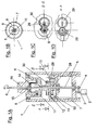
- Figure 1A shows a cross-sectional side view through a handle portion of an exemplary electric toothbrush as proposed.
- the handle portion 1 is driven by an electric motor 2 located in the lower section of the handle portion 1.
- the electric motor 2 comprises a drive axle 3 which is rotating during operation.
- the rotational motion of the drive axle 3 is converted by a first drive section 4 into a pivoting motion of the first drive shaft 5.
- the first drive section 4 is schematically indicated.
- the first drive section 4 may be formed by a gear wheel attached to the drive axle 3 of the electric motor 2 comprising an eccentric pin.
- the eccentric pin of the gear wheel in turn engages into a long hole of a lever attached to the first drive shaft 5.
- Each turn of the gear wheel thus provides an oscillating pivoting motion of the lever and thus of the first drive shaft 5.
- the first drive shaft 5 is a metal axle extending from the first drive section 4 to the upper section of the handle portion 1 such that its upper end 6 reaches through the housing 7 or more specifically through the second drive shaft 8. This way the first drive shaft is accessible from outside of the housing.
- the second drive shaft 8 is concentrically surrounding a section of the first drive shaft 5 and terminates the housing 7 of the handle portion 1 at its upper end.
- the concentric arrangement of the first drive shaft 5 and the second drive shaft 8 can be readily understood from figure 1B depicting a top view onto the upper end of the handle portion 1.
- the first drive shaft 5 forms the center of the concentrically arranged elements.
- the first drive shaft 5 extends through a bore 10 in the second drive shaft 8.
- the second drive shaft 8 is formed as a hollow element such that the first drive shaft 5 can reach through the second drive shaft 8.
- the second drive shaft 8 in turn is surrounded by a ring 9 formed of an elastomeric plastic material extending in a radial direction between the second drive shaft 8 and the housing 7 of the handle portion 1.
- the elastomeric ring 9 serves as a sealing between the second drive shaft 8 and the housing 7 in order to prevent any liquid from entering into the housing through the gap formed between the second drive shaft 8 and the housing 7.
- the elastomeric ring 9 may additionally or alternatively also serve as a bearing for the second drive shaft 8, thus allowing a pivoting motion of the second drive shaft 8 around an axis of rotation which is parallel to and identical with the axis of rotation of the first drive shaft 5.
- the second drive shaft 8 at its lower end comprises a mounting section 11 formed by a U-shaped recess 32 into which recess a holding projection 12 of the housing 8 engages in a form fit manner.
- the form fit only applies in a direction parallel to the axis of rotation of the second drive shaft 8 and therefore well allows a pivoting of the second drive shaft 8 around its axis of rotation.
- the second drive shaft 8 forms a hollow body having a through hole extending through the entire second drive shaft 8 through which the first drive shaft 5 extends.
- the handle portion comprises a sealing membrane 14 which seals the first drive shaft 5 with respect to the second drive shaft 8.
- the sealing membrane 14 extends across the entire cross-section of the hollow body formed by the second drive shaft 8 leaving only a tiny hole 15 in its center through which the first drive shaft 5 reaches through.
- the through hole 15 in the sealing membrane 14 is dimensioned such that it flexibly engages the first drive shaft 5 in all modes of operation effectively sealing the upper section of the hollow body formed by the drive shaft 8 with respect to the lower section of this hollow body.
- the sealing membrane 14 extends radially outwards from the first drive shaft 5 to the second drive shaft 8.
- the second drive shaft 8 is a two part element having an upper part 16 and a lower part 17 which are in form fit engagement with each other forming a recess in which the sealing membrane 14 is clamped and held in place.
- the upper end 6 of the first drive shaft 5 is flattened in order to provide a possibility for a form fit engagement with a complementary recess 17 of the head portion axle 18 of a head portion 19 of an electric toothbrush.
- the second drive axis 8 may at its upper end comprise a recess for form fit engagement with the housing 20 of a respective head portion of an electric toothbrush.
- the flattening of the upper end 6 of the first drive shaft 5 and the recess of the upper end of the second drive shaft 8 do enable a transfer of any pivoting motion of the first and second drive shafts 5, 8 to the respective parts 18, 20 of the head portion 19.
- FIG. 2 shows a side view of an exemplary head portion 19 of an electric toothbrush as proposed.
- the head portion mainly comprises a body or housing 20 and a bristle carrier 21 carrying a plurality of bristles for cleaning a user's teeth.
- the bristle carrier 21 is pivotably mounted on the housing 20 of the head portion 19. Therefore the bristle carrier 21 is attached to an axle 23 which when the head portion 19 is attached to the handle portion 1 is essentially perpendicular to the axis of rotation of the first and second drive shafts 5, 8 of the handle portion as well as to the handle portion axle 18.
- the head portion 19 When the head portion 19 is attached to the handle portion 1 any pivoting motion of the first drive shaft 5 is transferred to the head portion axle 18.
- the head portion axle 18 is pivotably mounted inside the housing 20. In order to transfer a pivoting motion of the head portion axle 18 into a pivoting motion of the bristle carrier 21 in a direction perpendicular to the axis of rotation of the head portion axle 18, the head portion comprises a head portion drive 24.
- the head portion drive 24 is a so called con rod drive.
- the head portion drive 24 is formed by a con rod 25 eccentrically mounted to the head portion axle 18.
- the con rod 25 at its upper end is connected to a con rod journal 26 which in turn is eccentrically mounted to the bristle carrier 21.
- the con rod 25 is rotatably mounted at the head portion axle 18 and the con rod journal 26 is rotatably mounted to the bristle carrier 21.
- the con rod 25 is slidedly mounted in a direction parallel to the axis of rotation of the head portion axle 18. This slidable motion is spring biased by a spring 27.
- the bristle carrier 21 When in operating engagement with each other the second drive shaft 8 of the handle portion 1 transfers a pivoting oscillating motion to the housing 20 of the head portion 19 of the electric toothbrush.
- the bristle carrier 21 not only experiences a pivoting oscillation around an axis of rotation 23 but also a pivoting around an axis of rotation parallel to the axis of rotation of the second drive shaft 8.
- This superposition of two pivoting motions in two perpendicular directions closely corresponds to the motion as it should be carried out by a person using a manual non-automatic toothbrush.
- a second drive section 13 mechanically connects the first drive shaft 5 to the second drive shaft 8.
- a first gear wheel 28 is rigidly attached to the first drive shaft 5.
- the first gear wheel 28 combs with a second gear wheel 29 which is pivotably supported by the housing 7 of the handle portion 1. Any pivoting motion of the first drive shaft 5 is transferred via the first gear wheel 28 to the second gear wheel 29.
- the second gear wheel carries an eccentric pin 30 which in turn engages a long hole 31 in the second drive shaft 8.
- the long hole 31 is located off axis with respect to the axis of rotation of the second drive shaft 8.
- any pivoting motion of the second gear wheel 29 leads to an oscillating translational motion of the eccentric pin 30 on a curved path.
- the pin 30 during its translation takes along the pivotably mounted second drive shaft 8 the second drive shaft 8 in turn is forced into a pivoting oscillation.
- FIG. 1C shows how the pin 30 is eccentrically mounted on the second gear wheel 29 and engages into the long hole 31 of the second drive shaft 8.
- FIG 1D the combing of the first and second gear wheels 28, 29 is depicted.
Landscapes
- Health & Medical Sciences (AREA)
- Dentistry (AREA)
- Epidemiology (AREA)
- Life Sciences & Earth Sciences (AREA)
- Animal Behavior & Ethology (AREA)
- General Health & Medical Sciences (AREA)
- Public Health (AREA)
- Veterinary Medicine (AREA)
- Brushes (AREA)
Priority Applications (4)
| Application Number | Priority Date | Filing Date | Title |
|---|---|---|---|
| EP10007421.0A EP2407124B1 (de) | 2010-07-17 | 2010-07-17 | Elektrische Zahnbürste |
| PCT/IB2011/053129 WO2012011025A1 (en) | 2010-07-17 | 2011-07-13 | Electric toothbrush |
| US13/181,770 US8701235B2 (en) | 2010-07-17 | 2011-07-13 | Electric toothbrush |
| CN201180035213.2A CN103002830B (zh) | 2010-07-17 | 2011-07-13 | 电动牙刷 |
Applications Claiming Priority (1)
| Application Number | Priority Date | Filing Date | Title |
|---|---|---|---|
| EP10007421.0A EP2407124B1 (de) | 2010-07-17 | 2010-07-17 | Elektrische Zahnbürste |
Publications (2)
| Publication Number | Publication Date |
|---|---|
| EP2407124A1 true EP2407124A1 (de) | 2012-01-18 |
| EP2407124B1 EP2407124B1 (de) | 2015-11-11 |
Family
ID=43304924
Family Applications (1)
| Application Number | Title | Priority Date | Filing Date |
|---|---|---|---|
| EP10007421.0A Not-in-force EP2407124B1 (de) | 2010-07-17 | 2010-07-17 | Elektrische Zahnbürste |
Country Status (4)
| Country | Link |
|---|---|
| US (1) | US8701235B2 (de) |
| EP (1) | EP2407124B1 (de) |
| CN (1) | CN103002830B (de) |
| WO (1) | WO2012011025A1 (de) |
Cited By (2)
| Publication number | Priority date | Publication date | Assignee | Title |
|---|---|---|---|---|
| WO2016042427A1 (en) * | 2014-09-16 | 2016-03-24 | Koninklijke Philips N.V. | Attachment with identification for personal care appliance and method |
| US10548699B2 (en) | 2016-08-03 | 2020-02-04 | Koninklijke Philips N.V. | Drive train assembly for a personal care device |
Families Citing this family (37)
| Publication number | Priority date | Publication date | Assignee | Title |
|---|---|---|---|---|
| JP5796408B2 (ja) * | 2011-08-24 | 2015-10-21 | オムロンヘルスケア株式会社 | 口腔ケア装置 |
| JP5794646B2 (ja) * | 2013-12-27 | 2015-10-14 | 日本電気株式会社 | 衛星測位システム、測位端末、測位方法、及びプログラム |
| CN105726151A (zh) * | 2016-04-07 | 2016-07-06 | 周建伟 | 电动牙刷头及其制成的电动牙刷 |
| EP3300685B1 (de) * | 2016-09-28 | 2019-10-30 | Braun GmbH | Elektrisch angetriebene vorrichtung |
| EP3300687B1 (de) | 2016-09-28 | 2019-04-24 | Braun GmbH | Elektrisch angetriebene vorrichtung |
| EP3300689B1 (de) | 2016-09-28 | 2019-08-07 | Braun GmbH | Elektrisch angetriebene vorrichtung |
| EP3300688B1 (de) * | 2016-09-28 | 2019-08-07 | Braun GmbH | Elektrisch angetriebene vorrichtung |
| JP6775199B2 (ja) * | 2017-05-18 | 2020-10-28 | パナソニックIpマネジメント株式会社 | 電動歯ブラシ |
| CA187611S (en) | 2017-11-02 | 2020-05-25 | Braun Gmbh | Head for electric toothbrush |
| USD893881S1 (en) | 2017-11-17 | 2020-08-25 | Colgate-Palmolive Company | Oral care apparatus |
| USD858997S1 (en) | 2017-11-17 | 2019-09-10 | Colgate-Palmolive Company | Tracking module for an oral care implement |
| USD858105S1 (en) | 2017-11-17 | 2019-09-03 | Colgate-Palmolive Company | Oral care implement |
| EP3501335B1 (de) | 2017-12-20 | 2020-06-17 | The Gillette Company LLC | Zahnbürste |
| EP3501334B1 (de) | 2017-12-20 | 2020-06-24 | The Gillette Company LLC | Mundpflegevorrichtung |
| EP3501333B1 (de) | 2017-12-20 | 2020-06-24 | The Gillette Company LLC | Zahnbürste |
| PL3524091T3 (pl) | 2018-02-09 | 2025-06-23 | The Gillette Company Llc | Ręczne narzędzie do higieny jamy ustnej |
| USD960581S1 (en) | 2018-02-09 | 2022-08-16 | The Gillette Company Llc | Toothbrush head |
| EP3524093A1 (de) | 2018-02-09 | 2019-08-14 | The Gillette Company LLC | Verfahren zur herstellung eines mundpflegegeräts |
| USD953744S1 (en) | 2019-02-08 | 2022-06-07 | Braun Gmbh | Head for electric toothbrush |
| EP3995039B1 (de) | 2020-11-06 | 2023-11-08 | The Gillette Company LLC | Griff für ein körperpflegegerät sowie körperpflegegerät |
| EP3995037B1 (de) | 2020-11-06 | 2025-04-16 | The Gillette Company LLC | Griff für ein körperpflegegerät sowie körperpflegegerät |
| EP3854346B1 (de) | 2020-01-22 | 2022-09-21 | The Gillette Company LLC | Verfahren zur herstellung eines griffs für ein elektrisch betriebenes körperpflegegerät |
| EP3892234B1 (de) * | 2020-04-08 | 2023-11-15 | The Gillette Company LLC | Griff für ein elektrisch betriebenes körperpflegegerät und körperpflegegerät |
| EP3995041A1 (de) | 2020-11-06 | 2022-05-11 | The Gillette Company LLC | Polymeres griffmaterial und dessen verwendung |
| USD957135S1 (en) | 2020-07-02 | 2022-07-12 | The Gillette Company Llc | Toothbrush head |
| USD1014095S1 (en) | 2020-07-02 | 2024-02-13 | The Gillette Company Llc. | Toothbrush |
| PL3995038T3 (pl) | 2020-11-06 | 2025-06-16 | The Gillette Company Llc | Rękojeść urządzenia do higieny osobistej i urządzenie do higieny osobistej |
| PL3995040T3 (pl) | 2020-11-06 | 2025-06-16 | The Gillette Company Llc | Rękojeść urządzenia do higieny osobistej i urządzenie do higieny osobistej |
| PL3995042T3 (pl) | 2020-11-06 | 2025-07-21 | The Gillette Company Llc | Rękojeść urządzenia do higieny osobistej i urządzenie do higieny osobistej |
| USD994341S1 (en) | 2020-11-06 | 2023-08-08 | The Gillette Company Llc | Toothbrush |
| PL3995282T3 (pl) | 2020-11-06 | 2025-11-03 | The Gillette Company Llc | Sposób wytwarzania rączki do przyrządu do higieny osobistej |
| CA203877S (en) | 2020-12-02 | 2023-04-17 | Braun Gmbh | Head for electric toothbrush |
| USD1033909S1 (en) | 2020-12-11 | 2024-07-09 | Braun Gmbh | Electric toothbrush |
| USD1051608S1 (en) | 2021-05-04 | 2024-11-19 | The Gillette Company Llc | Handle for battery operated toothbrush |
| USD1033910S1 (en) | 2021-07-02 | 2024-07-09 | Braun Gmbh | Handle for electric toothbrush |
| CN113796982B (zh) * | 2021-09-23 | 2023-05-30 | 无锡爱齿一生科技有限公司 | 一种便于拆装的电动牙刷 |
| CN114869524A (zh) * | 2022-06-13 | 2022-08-09 | 雷德贵 | 一种多功能刷头及多功能电动牙刷 |
Citations (4)
| Publication number | Priority date | Publication date | Assignee | Title |
|---|---|---|---|---|
| DE3544256A1 (de) | 1985-12-14 | 1987-06-19 | Braun Ag | Zahnbuerste mit elektromotorischem antrieb |
| DE4138021A1 (de) * | 1991-11-19 | 1993-05-27 | Gimelli Produktions Ag | Elektrische zahnbuerste |
| DE19627752A1 (de) * | 1996-07-10 | 1998-01-15 | Braun Ag | Elektrische Zahnbürste |
| US20060021165A1 (en) * | 2002-11-28 | 2006-02-02 | Bernhard Boland | Electric toothbrush |
Family Cites Families (5)
| Publication number | Priority date | Publication date | Assignee | Title |
|---|---|---|---|---|
| US6347425B1 (en) * | 2000-06-28 | 2002-02-19 | Colgate-Palmolive Company | Powered toothbrush having three dimensional rotational head motion |
| US20030066145A1 (en) * | 2001-10-04 | 2003-04-10 | Prineppi Frank J. | Electric toothbrushes |
| DE102006060132A1 (de) * | 2006-12-18 | 2008-06-19 | Braun Gmbh | Zahnbürste sowie Aufsatzteil hierfür |
| EP2107892B1 (de) * | 2007-02-02 | 2018-10-10 | The Gillette Company | Bürstenteil für eine elektrische zahnbürste |
| CN101461739A (zh) * | 2009-01-13 | 2009-06-24 | 王勇 | 兼具横刷和竖刷效果的电动牙刷 |
-
2010
- 2010-07-17 EP EP10007421.0A patent/EP2407124B1/de not_active Not-in-force
-
2011
- 2011-07-13 CN CN201180035213.2A patent/CN103002830B/zh not_active Expired - Fee Related
- 2011-07-13 US US13/181,770 patent/US8701235B2/en not_active Expired - Fee Related
- 2011-07-13 WO PCT/IB2011/053129 patent/WO2012011025A1/en not_active Ceased
Patent Citations (4)
| Publication number | Priority date | Publication date | Assignee | Title |
|---|---|---|---|---|
| DE3544256A1 (de) | 1985-12-14 | 1987-06-19 | Braun Ag | Zahnbuerste mit elektromotorischem antrieb |
| DE4138021A1 (de) * | 1991-11-19 | 1993-05-27 | Gimelli Produktions Ag | Elektrische zahnbuerste |
| DE19627752A1 (de) * | 1996-07-10 | 1998-01-15 | Braun Ag | Elektrische Zahnbürste |
| US20060021165A1 (en) * | 2002-11-28 | 2006-02-02 | Bernhard Boland | Electric toothbrush |
Cited By (4)
| Publication number | Priority date | Publication date | Assignee | Title |
|---|---|---|---|---|
| WO2016042427A1 (en) * | 2014-09-16 | 2016-03-24 | Koninklijke Philips N.V. | Attachment with identification for personal care appliance and method |
| RU2697540C2 (ru) * | 2014-09-16 | 2019-08-15 | Конинклейке Филипс Н.В. | Насадка с идентификацией для индивидуального устройства ухода и способ |
| US10849728B2 (en) | 2014-09-16 | 2020-12-01 | Koninklijke Philips N.V. | Attachment with identification for personal care appliance and method |
| US10548699B2 (en) | 2016-08-03 | 2020-02-04 | Koninklijke Philips N.V. | Drive train assembly for a personal care device |
Also Published As
| Publication number | Publication date |
|---|---|
| WO2012011025A1 (en) | 2012-01-26 |
| US20120011667A1 (en) | 2012-01-19 |
| US8701235B2 (en) | 2014-04-22 |
| CN103002830B (zh) | 2015-12-16 |
| CN103002830A (zh) | 2013-03-27 |
| EP2407124B1 (de) | 2015-11-11 |
Similar Documents
| Publication | Publication Date | Title |
|---|---|---|
| EP2407124B1 (de) | Elektrische Zahnbürste | |
| EP2529693B1 (de) | Dentalgerät | |
| US4053983A (en) | Prophylactic angle head for use with a dental handpiece | |
| US20030126700A1 (en) | Toothbrush with oppositely reciprocating brush heads | |
| EP2700330A1 (de) | Bürsteneinsatz für eine Hautbehandlungsvorrichtung | |
| JPH06121710A (ja) | 電動歯ブラシ | |
| US20150216640A1 (en) | Multi-function electric brush apparatus and systems useful for cleaning teeth and interdental spaces | |
| JP3005608B2 (ja) | 電動歯ブラシ | |
| JP3179819B2 (ja) | 電動歯ブラシ | |
| US8683639B2 (en) | Mechanical toothbrush and drive mechanism therefor (embodiments) | |
| JP3372658B2 (ja) | 電動歯ブラシ | |
| JP5717258B2 (ja) | 歯ブラシ兼用電動歯間ブラシ | |
| US11832715B2 (en) | Skin treatment device | |
| JPH01166791A (ja) | 電動ひげそり装置 | |
| JPH11342140A (ja) | 電動歯ブラシ | |
| JP5095194B2 (ja) | 電動歯ブラシ | |
| JP7203030B6 (ja) | 動的ブラシヘッドを有する電動式ユーティリティブラシ | |
| CN1976647B (zh) | 可变功能的牙刷 | |
| JPH06245819A (ja) | 電動歯ブラシ | |
| CN217430226U (zh) | 一种可替换行星轨道360度旋转牙刷 | |
| CN2566814Y (zh) | 一种电动牙刷 | |
| CN117414224A (zh) | 旋转顺齿电动牙刷 | |
| JPH0373105A (ja) | 電動歯ぶらし | |
| JPH0560322U (ja) | 電動歯ブラシ | |
| JP2000279432A (ja) | 電動歯ブラシ |
Legal Events
| Date | Code | Title | Description |
|---|---|---|---|
| AK | Designated contracting states |
Kind code of ref document: A1 Designated state(s): AL AT BE BG CH CY CZ DE DK EE ES FI FR GB GR HR HU IE IS IT LI LT LU LV MC MK MT NL NO PL PT RO SE SI SK SM TR |
|
| AX | Request for extension of the european patent |
Extension state: BA ME RS |
|
| PUAI | Public reference made under article 153(3) epc to a published international application that has entered the european phase |
Free format text: ORIGINAL CODE: 0009012 |
|
| 17P | Request for examination filed |
Effective date: 20120516 |
|
| GRAP | Despatch of communication of intention to grant a patent |
Free format text: ORIGINAL CODE: EPIDOSNIGR1 |
|
| INTG | Intention to grant announced |
Effective date: 20150619 |
|
| GRAS | Grant fee paid |
Free format text: ORIGINAL CODE: EPIDOSNIGR3 |
|
| GRAA | (expected) grant |
Free format text: ORIGINAL CODE: 0009210 |
|
| AK | Designated contracting states |
Kind code of ref document: B1 Designated state(s): AL AT BE BG CH CY CZ DE DK EE ES FI FR GB GR HR HU IE IS IT LI LT LU LV MC MK MT NL NO PL PT RO SE SI SK SM TR |
|
| REG | Reference to a national code |
Ref country code: GB Ref legal event code: FG4D |
|
| REG | Reference to a national code |
Ref country code: CH Ref legal event code: EP |
|
| REG | Reference to a national code |
Ref country code: IE Ref legal event code: FG4D |
|
| REG | Reference to a national code |
Ref country code: AT Ref legal event code: REF Ref document number: 760050 Country of ref document: AT Kind code of ref document: T Effective date: 20151215 |
|
| REG | Reference to a national code |
Ref country code: DE Ref legal event code: R096 Ref document number: 602010028898 Country of ref document: DE |
|
| REG | Reference to a national code |
Ref country code: LT Ref legal event code: MG4D |
|
| REG | Reference to a national code |
Ref country code: NL Ref legal event code: MP Effective date: 20160211 |
|
| REG | Reference to a national code |
Ref country code: AT Ref legal event code: MK05 Ref document number: 760050 Country of ref document: AT Kind code of ref document: T Effective date: 20151111 |
|
| PG25 | Lapsed in a contracting state [announced via postgrant information from national office to epo] |
Ref country code: IS Free format text: LAPSE BECAUSE OF FAILURE TO SUBMIT A TRANSLATION OF THE DESCRIPTION OR TO PAY THE FEE WITHIN THE PRESCRIBED TIME-LIMIT Effective date: 20160311 Ref country code: LT Free format text: LAPSE BECAUSE OF FAILURE TO SUBMIT A TRANSLATION OF THE DESCRIPTION OR TO PAY THE FEE WITHIN THE PRESCRIBED TIME-LIMIT Effective date: 20151111 Ref country code: HR Free format text: LAPSE BECAUSE OF FAILURE TO SUBMIT A TRANSLATION OF THE DESCRIPTION OR TO PAY THE FEE WITHIN THE PRESCRIBED TIME-LIMIT Effective date: 20151111 Ref country code: NO Free format text: LAPSE BECAUSE OF FAILURE TO SUBMIT A TRANSLATION OF THE DESCRIPTION OR TO PAY THE FEE WITHIN THE PRESCRIBED TIME-LIMIT Effective date: 20160211 Ref country code: IT Free format text: LAPSE BECAUSE OF FAILURE TO SUBMIT A TRANSLATION OF THE DESCRIPTION OR TO PAY THE FEE WITHIN THE PRESCRIBED TIME-LIMIT Effective date: 20151111 Ref country code: ES Free format text: LAPSE BECAUSE OF FAILURE TO SUBMIT A TRANSLATION OF THE DESCRIPTION OR TO PAY THE FEE WITHIN THE PRESCRIBED TIME-LIMIT Effective date: 20151111 Ref country code: NL Free format text: LAPSE BECAUSE OF FAILURE TO SUBMIT A TRANSLATION OF THE DESCRIPTION OR TO PAY THE FEE WITHIN THE PRESCRIBED TIME-LIMIT Effective date: 20151111 |
|
| PG25 | Lapsed in a contracting state [announced via postgrant information from national office to epo] |
Ref country code: PT Free format text: LAPSE BECAUSE OF FAILURE TO SUBMIT A TRANSLATION OF THE DESCRIPTION OR TO PAY THE FEE WITHIN THE PRESCRIBED TIME-LIMIT Effective date: 20160311 Ref country code: LV Free format text: LAPSE BECAUSE OF FAILURE TO SUBMIT A TRANSLATION OF THE DESCRIPTION OR TO PAY THE FEE WITHIN THE PRESCRIBED TIME-LIMIT Effective date: 20151111 Ref country code: FI Free format text: LAPSE BECAUSE OF FAILURE TO SUBMIT A TRANSLATION OF THE DESCRIPTION OR TO PAY THE FEE WITHIN THE PRESCRIBED TIME-LIMIT Effective date: 20151111 Ref country code: SE Free format text: LAPSE BECAUSE OF FAILURE TO SUBMIT A TRANSLATION OF THE DESCRIPTION OR TO PAY THE FEE WITHIN THE PRESCRIBED TIME-LIMIT Effective date: 20151111 Ref country code: GR Free format text: LAPSE BECAUSE OF FAILURE TO SUBMIT A TRANSLATION OF THE DESCRIPTION OR TO PAY THE FEE WITHIN THE PRESCRIBED TIME-LIMIT Effective date: 20160212 Ref country code: PL Free format text: LAPSE BECAUSE OF FAILURE TO SUBMIT A TRANSLATION OF THE DESCRIPTION OR TO PAY THE FEE WITHIN THE PRESCRIBED TIME-LIMIT Effective date: 20151111 Ref country code: AT Free format text: LAPSE BECAUSE OF FAILURE TO SUBMIT A TRANSLATION OF THE DESCRIPTION OR TO PAY THE FEE WITHIN THE PRESCRIBED TIME-LIMIT Effective date: 20151111 |
|
| PG25 | Lapsed in a contracting state [announced via postgrant information from national office to epo] |
Ref country code: CZ Free format text: LAPSE BECAUSE OF FAILURE TO SUBMIT A TRANSLATION OF THE DESCRIPTION OR TO PAY THE FEE WITHIN THE PRESCRIBED TIME-LIMIT Effective date: 20151111 |
|
| REG | Reference to a national code |
Ref country code: DE Ref legal event code: R097 Ref document number: 602010028898 Country of ref document: DE |
|
| PG25 | Lapsed in a contracting state [announced via postgrant information from national office to epo] |
Ref country code: RO Free format text: LAPSE BECAUSE OF FAILURE TO SUBMIT A TRANSLATION OF THE DESCRIPTION OR TO PAY THE FEE WITHIN THE PRESCRIBED TIME-LIMIT Effective date: 20151111 Ref country code: EE Free format text: LAPSE BECAUSE OF FAILURE TO SUBMIT A TRANSLATION OF THE DESCRIPTION OR TO PAY THE FEE WITHIN THE PRESCRIBED TIME-LIMIT Effective date: 20151111 Ref country code: DK Free format text: LAPSE BECAUSE OF FAILURE TO SUBMIT A TRANSLATION OF THE DESCRIPTION OR TO PAY THE FEE WITHIN THE PRESCRIBED TIME-LIMIT Effective date: 20151111 Ref country code: SK Free format text: LAPSE BECAUSE OF FAILURE TO SUBMIT A TRANSLATION OF THE DESCRIPTION OR TO PAY THE FEE WITHIN THE PRESCRIBED TIME-LIMIT Effective date: 20151111 Ref country code: SM Free format text: LAPSE BECAUSE OF FAILURE TO SUBMIT A TRANSLATION OF THE DESCRIPTION OR TO PAY THE FEE WITHIN THE PRESCRIBED TIME-LIMIT Effective date: 20151111 |
|
| PLBE | No opposition filed within time limit |
Free format text: ORIGINAL CODE: 0009261 |
|
| STAA | Information on the status of an ep patent application or granted ep patent |
Free format text: STATUS: NO OPPOSITION FILED WITHIN TIME LIMIT |
|
| 26N | No opposition filed |
Effective date: 20160812 |
|
| PGFP | Annual fee paid to national office [announced via postgrant information from national office to epo] |
Ref country code: DE Payment date: 20160801 Year of fee payment: 7 |
|
| PG25 | Lapsed in a contracting state [announced via postgrant information from national office to epo] |
Ref country code: SI Free format text: LAPSE BECAUSE OF FAILURE TO SUBMIT A TRANSLATION OF THE DESCRIPTION OR TO PAY THE FEE WITHIN THE PRESCRIBED TIME-LIMIT Effective date: 20151111 |
|
| PG25 | Lapsed in a contracting state [announced via postgrant information from national office to epo] |
Ref country code: BE Free format text: LAPSE BECAUSE OF FAILURE TO SUBMIT A TRANSLATION OF THE DESCRIPTION OR TO PAY THE FEE WITHIN THE PRESCRIBED TIME-LIMIT Effective date: 20151111 |
|
| REG | Reference to a national code |
Ref country code: CH Ref legal event code: PL |
|
| GBPC | Gb: european patent ceased through non-payment of renewal fee |
Effective date: 20160717 |
|
| PG25 | Lapsed in a contracting state [announced via postgrant information from national office to epo] |
Ref country code: MC Free format text: LAPSE BECAUSE OF FAILURE TO SUBMIT A TRANSLATION OF THE DESCRIPTION OR TO PAY THE FEE WITHIN THE PRESCRIBED TIME-LIMIT Effective date: 20151111 |
|
| PG25 | Lapsed in a contracting state [announced via postgrant information from national office to epo] |
Ref country code: FR Free format text: LAPSE BECAUSE OF NON-PAYMENT OF DUE FEES Effective date: 20160801 Ref country code: LI Free format text: LAPSE BECAUSE OF NON-PAYMENT OF DUE FEES Effective date: 20160731 Ref country code: CH Free format text: LAPSE BECAUSE OF NON-PAYMENT OF DUE FEES Effective date: 20160731 |
|
| REG | Reference to a national code |
Ref country code: FR Ref legal event code: ST Effective date: 20170331 |
|
| REG | Reference to a national code |
Ref country code: IE Ref legal event code: MM4A |
|
| PG25 | Lapsed in a contracting state [announced via postgrant information from national office to epo] |
Ref country code: GB Free format text: LAPSE BECAUSE OF NON-PAYMENT OF DUE FEES Effective date: 20160717 |
|
| PG25 | Lapsed in a contracting state [announced via postgrant information from national office to epo] |
Ref country code: IE Free format text: LAPSE BECAUSE OF NON-PAYMENT OF DUE FEES Effective date: 20160717 |
|
| PG25 | Lapsed in a contracting state [announced via postgrant information from national office to epo] |
Ref country code: LU Free format text: LAPSE BECAUSE OF NON-PAYMENT OF DUE FEES Effective date: 20160717 |
|
| REG | Reference to a national code |
Ref country code: DE Ref legal event code: R119 Ref document number: 602010028898 Country of ref document: DE |
|
| PG25 | Lapsed in a contracting state [announced via postgrant information from national office to epo] |
Ref country code: DE Free format text: LAPSE BECAUSE OF NON-PAYMENT OF DUE FEES Effective date: 20180201 |
|
| PG25 | Lapsed in a contracting state [announced via postgrant information from national office to epo] |
Ref country code: CY Free format text: LAPSE BECAUSE OF FAILURE TO SUBMIT A TRANSLATION OF THE DESCRIPTION OR TO PAY THE FEE WITHIN THE PRESCRIBED TIME-LIMIT Effective date: 20151111 Ref country code: HU Free format text: LAPSE BECAUSE OF FAILURE TO SUBMIT A TRANSLATION OF THE DESCRIPTION OR TO PAY THE FEE WITHIN THE PRESCRIBED TIME-LIMIT; INVALID AB INITIO Effective date: 20100717 |
|
| PG25 | Lapsed in a contracting state [announced via postgrant information from national office to epo] |
Ref country code: MT Free format text: LAPSE BECAUSE OF NON-PAYMENT OF DUE FEES Effective date: 20160731 Ref country code: MK Free format text: LAPSE BECAUSE OF FAILURE TO SUBMIT A TRANSLATION OF THE DESCRIPTION OR TO PAY THE FEE WITHIN THE PRESCRIBED TIME-LIMIT Effective date: 20151111 Ref country code: TR Free format text: LAPSE BECAUSE OF FAILURE TO SUBMIT A TRANSLATION OF THE DESCRIPTION OR TO PAY THE FEE WITHIN THE PRESCRIBED TIME-LIMIT Effective date: 20151111 |
|
| PG25 | Lapsed in a contracting state [announced via postgrant information from national office to epo] |
Ref country code: BG Free format text: LAPSE BECAUSE OF FAILURE TO SUBMIT A TRANSLATION OF THE DESCRIPTION OR TO PAY THE FEE WITHIN THE PRESCRIBED TIME-LIMIT Effective date: 20151111 |
|
| PG25 | Lapsed in a contracting state [announced via postgrant information from national office to epo] |
Ref country code: AL Free format text: LAPSE BECAUSE OF FAILURE TO SUBMIT A TRANSLATION OF THE DESCRIPTION OR TO PAY THE FEE WITHIN THE PRESCRIBED TIME-LIMIT Effective date: 20151111 |