EP2406893B1 - Conception d'un canal de liaison pour commande d'un relais. - Google Patents
Conception d'un canal de liaison pour commande d'un relais. Download PDFInfo
- Publication number
- EP2406893B1 EP2406893B1 EP10709630.7A EP10709630A EP2406893B1 EP 2406893 B1 EP2406893 B1 EP 2406893B1 EP 10709630 A EP10709630 A EP 10709630A EP 2406893 B1 EP2406893 B1 EP 2406893B1
- Authority
- EP
- European Patent Office
- Prior art keywords
- relay
- dci
- ofdm
- node
- predetermined number
- Prior art date
- Legal status (The legal status is an assumption and is not a legal conclusion. Google has not performed a legal analysis and makes no representation as to the accuracy of the status listed.)
- Active
Links
- 238000013461 design Methods 0.000 title description 7
- 238000000034 method Methods 0.000 claims description 28
- 238000004891 communication Methods 0.000 claims description 23
- 230000011664 signaling Effects 0.000 claims 6
- 230000005540 biological transmission Effects 0.000 description 21
- 238000010586 diagram Methods 0.000 description 3
- 230000008901 benefit Effects 0.000 description 2
- 239000003795 chemical substances by application Substances 0.000 description 2
- 238000012545 processing Methods 0.000 description 2
- 238000012546 transfer Methods 0.000 description 2
- 241000699670 Mus sp. Species 0.000 description 1
- 101150071746 Pbsn gene Proteins 0.000 description 1
- 230000002776 aggregation Effects 0.000 description 1
- 238000004220 aggregation Methods 0.000 description 1
- 230000004075 alteration Effects 0.000 description 1
- 230000003321 amplification Effects 0.000 description 1
- 230000006399 behavior Effects 0.000 description 1
- 238000004590 computer program Methods 0.000 description 1
- 238000013500 data storage Methods 0.000 description 1
- 238000005516 engineering process Methods 0.000 description 1
- 239000000835 fiber Substances 0.000 description 1
- 230000006870 function Effects 0.000 description 1
- 238000002955 isolation Methods 0.000 description 1
- 239000004973 liquid crystal related substance Substances 0.000 description 1
- 230000007774 longterm Effects 0.000 description 1
- 230000007246 mechanism Effects 0.000 description 1
- 238000010295 mobile communication Methods 0.000 description 1
- 230000004048 modification Effects 0.000 description 1
- 238000012986 modification Methods 0.000 description 1
- 238000003199 nucleic acid amplification method Methods 0.000 description 1
- 230000003287 optical effect Effects 0.000 description 1
- 238000013515 script Methods 0.000 description 1
- 238000001228 spectrum Methods 0.000 description 1
- 238000006467 substitution reaction Methods 0.000 description 1
Images


Classifications
-
- H—ELECTRICITY
- H04—ELECTRIC COMMUNICATION TECHNIQUE
- H04L—TRANSMISSION OF DIGITAL INFORMATION, e.g. TELEGRAPHIC COMMUNICATION
- H04L27/00—Modulated-carrier systems
- H04L27/26—Systems using multi-frequency codes
-
- H—ELECTRICITY
- H04—ELECTRIC COMMUNICATION TECHNIQUE
- H04W—WIRELESS COMMUNICATION NETWORKS
- H04W72/00—Local resource management
- H04W72/20—Control channels or signalling for resource management
- H04W72/21—Control channels or signalling for resource management in the uplink direction of a wireless link, i.e. towards the network
-
- H—ELECTRICITY
- H04—ELECTRIC COMMUNICATION TECHNIQUE
- H04B—TRANSMISSION
- H04B7/00—Radio transmission systems, i.e. using radiation field
- H04B7/14—Relay systems
-
- H—ELECTRICITY
- H04—ELECTRIC COMMUNICATION TECHNIQUE
- H04L—TRANSMISSION OF DIGITAL INFORMATION, e.g. TELEGRAPHIC COMMUNICATION
- H04L5/00—Arrangements affording multiple use of the transmission path
- H04L5/003—Arrangements for allocating sub-channels of the transmission path
- H04L5/0053—Allocation of signaling, i.e. of overhead other than pilot signals
-
- H—ELECTRICITY
- H04—ELECTRIC COMMUNICATION TECHNIQUE
- H04L—TRANSMISSION OF DIGITAL INFORMATION, e.g. TELEGRAPHIC COMMUNICATION
- H04L7/00—Arrangements for synchronising receiver with transmitter
-
- H—ELECTRICITY
- H04—ELECTRIC COMMUNICATION TECHNIQUE
- H04W—WIRELESS COMMUNICATION NETWORKS
- H04W56/00—Synchronisation arrangements
-
- H—ELECTRICITY
- H04—ELECTRIC COMMUNICATION TECHNIQUE
- H04W—WIRELESS COMMUNICATION NETWORKS
- H04W72/00—Local resource management
- H04W72/20—Control channels or signalling for resource management
- H04W72/23—Control channels or signalling for resource management in the downlink direction of a wireless link, i.e. towards a terminal
-
- H—ELECTRICITY
- H04—ELECTRIC COMMUNICATION TECHNIQUE
- H04B—TRANSMISSION
- H04B7/00—Radio transmission systems, i.e. using radiation field
- H04B7/24—Radio transmission systems, i.e. using radiation field for communication between two or more posts
- H04B7/26—Radio transmission systems, i.e. using radiation field for communication between two or more posts at least one of which is mobile
- H04B7/2603—Arrangements for wireless physical layer control
- H04B7/2606—Arrangements for base station coverage control, e.g. by using relays in tunnels
-
- H—ELECTRICITY
- H04—ELECTRIC COMMUNICATION TECHNIQUE
- H04L—TRANSMISSION OF DIGITAL INFORMATION, e.g. TELEGRAPHIC COMMUNICATION
- H04L5/00—Arrangements affording multiple use of the transmission path
- H04L5/003—Arrangements for allocating sub-channels of the transmission path
- H04L5/0048—Allocation of pilot signals, i.e. of signals known to the receiver
- H04L5/005—Allocation of pilot signals, i.e. of signals known to the receiver of common pilots, i.e. pilots destined for multiple users or terminals
-
- H—ELECTRICITY
- H04—ELECTRIC COMMUNICATION TECHNIQUE
- H04W—WIRELESS COMMUNICATION NETWORKS
- H04W72/00—Local resource management
- H04W72/04—Wireless resource allocation
- H04W72/044—Wireless resource allocation based on the type of the allocated resource
- H04W72/0446—Resources in time domain, e.g. slots or frames
-
- H—ELECTRICITY
- H04—ELECTRIC COMMUNICATION TECHNIQUE
- H04W—WIRELESS COMMUNICATION NETWORKS
- H04W84/00—Network topologies
- H04W84/02—Hierarchically pre-organised networks, e.g. paging networks, cellular networks, WLAN [Wireless Local Area Network] or WLL [Wireless Local Loop]
- H04W84/04—Large scale networks; Deep hierarchical networks
- H04W84/042—Public Land Mobile systems, e.g. cellular systems
- H04W84/047—Public Land Mobile systems, e.g. cellular systems using dedicated repeater stations
-
- H—ELECTRICITY
- H04—ELECTRIC COMMUNICATION TECHNIQUE
- H04W—WIRELESS COMMUNICATION NETWORKS
- H04W88/00—Devices specially adapted for wireless communication networks, e.g. terminals, base stations or access point devices
- H04W88/02—Terminal devices
- H04W88/04—Terminal devices adapted for relaying to or from another terminal or user
Definitions
- the terms “user agent” and “UA” might in some cases refer to mobile devices such as mobile telephones, personal digital assistants, handheld or laptop computers, and similar devices that have telecommunications capabilities. Such a UA might consist of a UA and its associated removable memory module, such as but not limited to a Universal Integrated Circuit Card (UICC) that includes a Subscriber Identity Module (SIM) application, a Universal Subscriber Identity Module (USIM) application, or a Removable User Identity Module (R-UIM) application. Alternatively, such a UA might consist of the device itself without such a module. In other cases, the term “UA” might refer to devices that have similar capabilities but that are not transportable, such as desktop computers, set-top boxes, or network appliances. The term “UA” can also refer to any hardware or software component that can terminate a communication session for a user. Also, the terms “user agent,” “UA,” “user equipment,” “UE,” “user device” and “user node” might be used synonymously herein.
- UICC Universal Integrated Circuit Card
- LTE Long-term evolution
- an LTE system might include an Evolved Universal Terrestrial Radio Access Network (E-UTRAN) node B (eNB), a wireless access point, or a similar component rather than a traditional base station.
- E-UTRAN Evolved Universal Terrestrial Radio Access Network
- eNB Evolved Universal Terrestrial Radio Access Network node B
- wireless access point a wireless access point, or a similar component rather than a traditional base station.
- the term "access node” will refer to any component of the wireless network, such as a traditional base station, a wireless access point, or an LTE eNB, that creates a geographical area of reception and transmission coverage allowing a UA or a relay node to access other components in a telecommunications system.
- the term “access node” and “access device” may be used interchangeably, but it is understood that an access node may comprise a plurality of hardware and software.
- the term "access node” does not refer to a "relay node,” which is a component in a wireless network that is configured to extend or enhance the coverage created by an access node or another relay node.
- the access node and relay node are both radio components that may be present in a wireless communications network, and the terms “component” and “network node” may refer to an access node or relay node. It is understood that a component might operate as an access node or a relay node depending on its configuration and placement. However, a component is called a "relay node” only if it requires the wireless coverage of an access node or other relay node to access other components in a wireless communications system. Additionally, two or more relay nodes may used serially to extend or enhance coverage created by an access node.
- An LTE system can include protocols such as a Radio Resource Control (RRC) protocol, which is responsible for the assignment, configuration, and release of radio resources between a UA and a network node or other LTE equipment.
- RRC Radio Resource Control
- the RRC protocol is described in detail in the Third Generation Partnership Project (3GPP) Technical Specification (TS) 36.331.
- 3GPP Third Generation Partnership Project
- TS Technical Specification
- the two basic RRC modes for a UA are defined as "idle mode" and "connected mode.”
- the UA may exchange signals with the network and perform other related operations, while during the idle mode or state, the UA may shut down at least some of its connected mode operations. Idle and connected mode behaviors are described in detail in 3GPP TS 36.304 and TS 36.331.
- the signals that carry data between UAs, relay nodes, and access nodes can have frequency, time, and coding parameters and other characteristics that might be specified by a network node.
- a connection between any of these elements that has a specific set of such characteristics can be referred to as a resource.
- the terms "resource,” “communications connection,” “channel,” and “communications link” might be used synonymously herein.
- a network node typically establishes a different resource for each UA or other network nodes with which it is communicating at any particular time.
- EP1804442 discloses techniques for transparently relaying a signal using a plurality of frequency bands, wherein a RS communicates with a BS in a first frequency band and communicates with a MS within a sub-cell of the RS via a second frequency band different from the first frequency band.
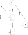
- FIG. 1 is a diagram illustrating a wireless communication system 100 using a relay node 102, according to an embodiment of the disclosure.
- the present disclosure relates to the use of relay nodes in wireless communications networks, such as LTE or LTE-Advanced (LTE-A) networks, and all of the disclosed and claimed embodiments could be implemented in an LTE-A network.
- LTE corresponds to release 8 and release 9
- LTE-A corresponds to release 10 and possibly beyond release 10.
- the relay node 102 can amplify or repeat a signal received from a UA 110 and cause the modified signal to be received at an access node 106.
- the relay node 102 receives a signal with data from the UA 110 and then generates a new and/or different signal to transmit the data to the access node 106.
- the relay node 102 can also receive data from the access node 106 and deliver the data to the UA 110.
- the relay node 102 might be placed near the edges of a cell so that the UA 110 can communicate with the relay node 102 rather than communicating directly with the access node 106 for that cell.
- a cell is a geographical area of reception and transmission coverage. Cells can overlap with each other. In the typical example, there is one access node associated with each cell. The size of a cell is determined by factors such as frequency band, power level, and channel conditions.
- Relay nodes such as relay node 102, can be used to enhance coverage within or near a cell, or to extend the size of coverage of a cell. Additionally, the use of a relay node 102 can enhance throughput of a signal within a cell because the UA 110 can access the relay node 102 at a higher data rate or a lower power transmission than the UA 110 might use when communicating directly with the access node 106 for that cell. Transmission at a higher data rate using the same amount of bandwidth creates higher spectrum efficiency, and lower power benefits the UA 110 by consuming less battery power.
- Relay nodes generally, can be divided into three types: layer one relay nodes, layer two relay nodes, and layer three relay nodes.
- a layer one relay node is essentially a repeater that can retransmit a transmission without any modification other than amplification and slight delay.
- a layer two relay node can demodulate and decode a transmission that it receives, re-encode the result of the decoding, and then transmit the modulated data.
- a layer three relay node can have full radio resource control capabilities and can thus function similarly to an access node.
- the radio resource control protocols used by a relay node may be the same as those used by an access node, and the relay node may have a unique cell identity typically used by an access node.
- a relay node is distinguished from an access node by the fact that it requires the presence of at least one access node (and the cell associated with that access node) or other relay node to access other components in a telecommunications system.
- the illustrative embodiments are primarily concerned with layer two or layer three relay nodes. Therefore, as used herein, the term "relay node" will not refer to layer one relay nodes, unless specifically stated otherwise.
- the links that allow wireless communication can be said to be of three distinct types.
- Third, communication that passes directly between the UA 110 and the access node 106 without passing through the relay node 102 is said to occur over a direct link 112.
- the terms "access link,” “relay link,” and “direct link” are used in this document according to the meaning described by Figure 1 .
- the carrier downlink subframe 200 may be transmitted by the access node 106 and received by the relay node 102 via the relay link and/or the UA 110 via the direct link 112.
- the carrier downlink subframe 200 comprises a plurality of orthogonal frequency multiplexing (OFDM) symbols sequenced from left to right from symbol 0 to symbol M-1, where the symbol 0 is transmitted by the access node 106 before the symbol 1 is transmitted by the access node 106, where the symbol 1 is transmitted by the access node 106 before the symbol 2 is transmitted by the access node 106, and so forth.
- An OFDM symbol is different from a data symbol.
- a data symbol is user information that has gone through at least one encoding step.
- An OFDM symbol is a series of data symbols, each modulated on a contiguous series of OFDM subcarriers.
- a collection of M symbols comprises a physical resource block.
- the carrier downlink subframe 200 comprises a plurality of physical resource blocks. While Figure 2 illustrates the carrier downlink subframe 200 comprising 50 physical resource blocks RB0 through RB49, it is understood that in other embodiments the carrier downlink subframe 200 may comprise either fewer or more resource blocks.
- Downlink control information may be provided in the first OFDM symbols 202 of the subframe 200.
- the downlink control information provided in the first OFDM symbols 202 may comprise one or more of a physical downlink control channel (PDCCH), a physical control format information channel (PCFICH), and a physical hybrid automatic repeat request indicator channel (PHICH). These control channels are intended for the use of UEs and may be ignored by the relay node.
- the remainder of the OFDM symbols in the downlink subframe 200 after the first block 202 may be referred to as a physical downlink shared channel (PDSCH) 204 that in LTE is intended for user plane data being sent to UEs.
- PDSCH physical downlink shared channel
- the PDSCH 204 may comprise a relay downlink control information (R-DCI) block 206 containing control information directed to the relay node 102.
- R-DCI relay downlink control information
- the relay node 102 is in a fixed location and has good link quality.
- the R-DCI block 206 is preferably transmitted by the access node 106 in about a middle of or a center frequency range of the resource blocks.
- the number of resource blocks used for the R-DCI block 206 may be pre-configured and/or fixed. In another embodiment, however, the number of resource blocks used for the R-DCI block 206 may be dynamically defined and may be conveyed to the relay node 102 by a variety of mechanisms including in a higher layer message.
- the R-DCI block 206 may be transmitted by the access node 106 between resource block 19 and resource block 30, for example in one or more of resource block 20 through resource block 29.
- the R-DCI block 206 is transmitted by the access node 106 in a plurality of adjacent resource blocks. In an embodiment, the R-DCI block 206 is transmitted by the access node 106 in a plurality of contiguous resource blocks. In another embodiment, the R-DCI block 206 is transmitted by the access node 106 in a plurality of non-contiguous resource blocks. It is contemplated by the present disclosure that, by confining the resource blocks of the R-DCI block 206 to a sub-range of the carrier frequency band, some embodiments of the relay node 102 may deploy a radio transceiver configured to operate over the subject sub-range of the carrier frequency band, possibly reducing the cost of the relay nodes 102.
- the access node 106 may modulate and transmit the R-DCI block 206 using a relatively high modulation order because the relay link 104 has a relatively high link quality.
- the access node 106 may be configured to use one of a 16-quadrature amplitude modulation (QAM) modulation constellation, a 64-QAM modulation constellation, and a 256-QAM modulation constellation to modulate and transmit the R-DCI block 206 to the relay node 102.
- the R-DCI in one subframe may use a different modulation constellation than in a previous or subsequent subframe.
- the relay node 102 may be configured to demodulate the R-DCI block 206 using one of a 16-QAM modulation constellation, a 64-QAM modulation constellation, and a 256-QAM modulation constellation.
- the modulation information is pre-configured and/or fixed.
- the R-DCI block 206 may comprise a fixed number of OFDM symbols, for example one OFDM symbol or two OFDM symbols. Alternatively, in another embodiment, the R-DCI block 206 may comprise a variable number N of OFDM symbols. The present disclosure contemplates a number of design alternatives for providing the value of the number N to the relay node 102.
- the R-DCI block 206 may comprise a relay physical control format information channel (R-PCFICH) that conveys the value of the number N from the access node 106 to the relay node 102.
- R-PCFICH may be located in the first OFDM symbol of the R-DCI block 206.
- the access node 106 may convey and/or signal the value of the number N to the relay node 102 via one of a broadcast control channel (BCCH) and a medium access control (MAC) control element. In another embodiment, the access node 106 may convey and/or signal the value of the number N to the relay node 102 via a radio resource control (RRC) element. In another embodiment, the access node 106 may convey and/or signal the value of the number N to the relay node 102 via a higher layer message.
- BCCH broadcast control channel
- MAC medium access control
- RRC radio resource control
- the access node 106 may convey and/or signal the value of the number N to the relay node 102 via a higher layer message.
- the R-DCI block 206 may comprise the R-PCFICH information described above. Additionally, in an embodiment, the R-DCI block 206 may further comprise a relay physical downlink control channel (R-PDCCH) and/or a relay downlink physical hybrid automatic repeat request indicator channel (R-PHICH). In an embodiment, the number of OFDM symbols and/or the number of resource blocks allocated to the R-PCFICH, the R-PDCCH, and the R-PHICH may be configured by the access node 106.
- R-PDCCH relay physical downlink control channel
- R-PHICH relay downlink physical hybrid automatic repeat request indicator channel
- the relay data may be placed anywhere in the PDSCH block 204 but not in the R-DCI block 206.
- the relay data may be assigned and modulated anywhere in the PDSCH 204 or following the R-DCI 206.
- the relay data may comprise traffic for the relay node 102 to relay on to the UA 110 via the access link 108.
- the relay data may also comprise higher layer control signals directed to the relay node 102.
- the downlink grants for the relay data may be placed in the same resource blocks that are allocated to the R-DCI block 206 for symbols after the R-DCI block 206 has been transmitted, for example the second block 208.
- the downlink grants for the relay data may be assigned to a different set of resource blocks, for example the third block 210.
- a UA 110 may be in communication with the access node 106 via the direct link 112 and may receive a downlink grant for data in the fourth block 212.
- the location of the second, third, and fourth blocks 208, 210, 212 are exemplary and may be located in different places within the PDSCH block 204.
- a legacy UA 110 may not be assigned a downlink grant in the second block 208.
- a future or more advanced UA 110 may be assigned a downlink grant in the second block 208.
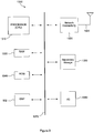
- FIG. 3 illustrates an example of a system 1300 that includes a processing component 1310 suitable for implementing one or more embodiments disclosed herein.
- the system 1300 might include network connectivity devices 1320, random access memory (RAM) 1330, read only memory (ROM) 1340, secondary storage 1350, and input/output (I/O) devices 1360. These components might communicate with one another via a bus 1370. In some cases, some of these components may not be present or may be combined in various combinations with one another or with other components not shown.
- DSP digital signal processor
- the processor 1310 executes instructions, codes, computer programs, or scripts that it might access from the network connectivity devices 1320, RAM 1330, ROM 1340, or secondary storage 1350 (which might include various disk-based systems such as hard disk, floppy disk, or optical disk). While only one CPU 1310 is shown, multiple processors may be present. Thus, while instructions may be discussed as being executed by a processor, the instructions may be executed simultaneously, serially, or otherwise by one or multiple processors.
- the processor 1310 may be implemented as one or more CPU chips.
- the network connectivity devices 1320 may take the form of modems, modem banks, Ethernet devices, universal serial bus (USB) interface devices, serial interfaces, token ring devices, fiber distributed data interface (FDDI) devices, wireless local area network (WLAN) devices, radio transceiver devices such as code division multiple access (CDMA) devices, global system for mobile communications (GSM) radio transceiver devices, worldwide interoperability for microwave access (WiMAX) devices, and/or other well-known devices for connecting to networks.
- These network connectivity devices 1320 may enable the processor 1310 to communicate with the Internet or one or more telecommunications networks or other networks from which the processor 1310 might receive information or to which the processor 1310 might output information.
- the network connectivity devices 1320 might also include one or more transceiver components 1325 capable of transmitting and/or receiving data wirelessly.
- the RAM 1330 might be used to store volatile data and perhaps to store instructions that are executed by the processor 1310.
- the ROM 1340 is a non-volatile memory device that typically has a smaller memory capacity than the memory capacity of the secondary storage 1350. ROM 1340 might be used to store instructions and perhaps data that are read during execution of the instructions. Access to both RAM 1330 and ROM 1340 is typically faster than to secondary storage 1350.
- the secondary storage 1350 is typically comprised of one or more disk drives or tape drives and might be used for non-volatile storage of data or as an over-flow data storage device if RAM 1330 is not large enough to hold all working data. Secondary storage 1350 may be used to store programs that are loaded into RAM 1330 when such programs are selected for execution.
- the I/O devices 1360 may include liquid crystal displays (LCDs), touch screen displays, keyboards, keypads, switches, dials, mice, track balls, voice recognizers, card readers, paper tape readers, printers, video monitors, or other well-known input/output devices.
- the transceiver 1325 might be considered to be a component of the I/O devices 1360 instead of or in addition to being a component of the network connectivity devices 1320.
- Relays can be used to enhance system throughput and extend coverage.
- One way to view a relay in an LTE-A system is as two back-to-back transceivers, one that communicates with an access node and one that communicates with a UE. It is technically difficult and probably expensive to design a relay node that has sufficient radio frequency front-end isolation to allow the relay to receive and transmit on the same frequency. This has the implication that there may need to be some sort of time-division duplex (TDD) scheme that allows the relay to receive at one time on a particular frequency and later to transmit on it.
- TDD time-division duplex
- Relays are being specified for Release 10 (R10) deployments.
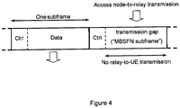
- a relay In order for a relay to support Release 8 (R8) UEs, there may need to be a downlink transmission of at least the physical control channel information (PDCCH) on every subframe.
- the control channel transmission comprises the first few OFDM symbols (between 1 and 4). If the transmission has only a PDCCH, it is called an MBSFN subframe. (There are legacy reasons for this name.)
- MBSFN subframes are used to allow downlink transfers from the access node to the relay on the relay link, as shown in Figure 4 .
- the downlink transfer of information from the access node to the relay is called the downlink backhaul.
- the relay transmits the control region (e.g., PDCCH) on the downlink (to the UE) and then in some way disables its transmitter and starts receiving the downlink transmission from the access node for at least most, if not all, of the remaining part of the MBSFN subframe.
- the control region e.g., PDCCH
- a relay may be required to transmit at least a PDCCH symbol on every subframe. This means that the only time a relay can receive downlink backhaul information from the access node is during an MBSFN subframe.
- the control region can be one or two OFDM symbols.
- the control region of a normal subframe can be up to 3 or 4 OFDM symbols.
- the relay cannot receive data from the access node during the control region of the relay MBSFN subframe. After the control region, the relay node can receive the data from the access node. Due to the potential discrepancy in the size of the control region of a normal subframe and the size of the control region of the relay MBSFN subframe, three different scenarios could arise.
- the relay MBSFN subframe has a larger control region than the corresponding access node subframe.
- the control region of the relay MBSFN subframe might have two OFDM symbols, while the control region of the access node subframe might have only one OFDM symbol.
- the relay may miss a part of the PDSCH of the access node subframe.
- the relay MBSFN subframe has a smaller control region than the corresponding access node subframe.
- the control region of relay MBSFN subframe might have two OFDM symbols, while the control region of the access node subframe might have three OFDM symbols.
- the relay may attempt to start receiving the PDSCH of the access node subframe earlier than necessary. The relay can ignore the received symbols until the PDSCH portion of the subframe starts. No data loss over the access node subframe will occur from point of view of the relay.
- the relay MBSFN subframe has the same size control region as the corresponding access node subframe.
- the control region of the relay MBSFN subframe might have two OFDM symbols, and the control region of the access node subframe might also have two OFDM symbols.
- the relay node can start to receive the PDSCH of the access node subframe exactly on time. But considering the relay switching delay, some data loss may occur.
- the access node subframe has a fixed-size control region.
- the access node subframe could be fixed at two OFDM symbols.
- the control region of the access node subframe could be fixed at three OFDM symbols.
- the relay will never miss any data from the access node.
- the size of the fixed control region for the access node during the relay MBSFN subframe can be configured semi-statically and broadcast on the broadcast control channel (BCCH) to the relay.
- BCCH broadcast control channel
- control region of the access node subframe is flexible. Inside the PDSCH, the access node transmits data to the relay starting from the second or third OFDM symbol regardless of the control region of the access node subframe.
- the first of these two solutions may be slightly preferred since it simplifies the relay control channel design and the relay data transmission from the access node.
- the starting time of the relay reception during a MBSFN subframe can be semi-statically configured to the relay node by the access node.
- the relay can receive the relay link downlink transmission only after transmitting the first N PDCCH MBSFN symbols on the access link. Since the PCFICH and PHICH are always transmitted in the first OFDM symbol, the existing R8 control channel design including PCFICH and PHICH cannot be received by the relay. Hence, a new control channel may need to be designed for the data being sent to the relay on the downlink backhaul. In an embodiment, the data could fit in the unused OFDM symbols that follow the PDCCH (i.e., in the PDSCH).
- the design of an efficient relay control channel may need to take into consideration that fact that the access node may transmit to donor cell UEs and relays during the same downlink subframe and the fact that the relatively small number of relays in a cell compared to UEs and the expected good link quality mean that the amount of relay control information may be limited and invariant.
- the amount of relay downlink control information may be small for one or more of the following three reasons.
- the control information consists mostly of downlink and uplink grants. Since the number of relays in the system is smaller than the number of UEs, the number of grants will be smaller. It can be assumed that there will be a data aggregation scheme such that the data for many UEs will be consolidated and sent to the relay using the relay's ID. Hence, the downlink relay control information may not require as much resource as the current PDCCH.
- the relay link is fixed and has better link quality than the access link.
- a higher modulation order on the physical control channel e.g., 16-QAM or 64-QAM
- spatial multiplexing may be used to reduce the required physical resources for the relay control channel.
- the relay link control information is directed to the relay node only (using the relay ID). Therefore, when the access node transmits multiple users' data to the relay, only one joint downlink grant is delivered to the relay node using the relay ID (i.e., there is no separate control information per user). This further reduces the control information amount for the relay link.
- Figure 7 shows the relay downlink control information (R-DCI) being transmitted in the resource blocks (RBs) at the center of the carrier.
- the number of RBs can be pre-configured.
- the number of OFDM symbols of the R-DCI is indicated by the relay physical control format indicator channel (R-PCFICH) in a manner similar to that of the PCFICH.
- R-PCFICH relay physical control format indicator channel
- the remaining OFDM symbols in the MBSFN subframe after the R-DCI can be used for downlink data transmission for the relay or LTE-A (R10) UEs. This area cannot be used for R8 UEs since they cannot understand an R-DCI that will be specified in a later release. From the scheduler point of view, the relay and the R10 UEs can be assigned any RBs over the PDSCH portion of the MBSFN subframe, while the R8 UEs can be assigned to any RBs outside the R-DCI.
- the R-PCFICH can be located at the first symbol of the R-DCI but spread in frequency for diversity gain.
- the relay after receiving the R-PCFICH, the relay blindly decodes the relay physical downlink control channel (R-PDCCH) based on the relay ID in a manner similar to how a R8 UE decodes the PDCCH.
- R-PDCCH relay physical downlink control channel
- grant messages can be formatted in a way that the relay knows how to receive data following the R-DCI or in the PDSCH. If the relay node successfully decodes the R-PDCCH, the relay node will be able to find any physical resource for the shared channel data transmission.
- the access node does not use the reserved R-PDCCH and R-PCFICH resources for data transmission with donor cell UEs.
- a few resource blocks in the middle of the downlink channel can be reserved to place the R-PDCCH and the R-PCFICH.
- the R-PDCCH may need to be kept as narrow as possible; however, as demand increases it may widen.
- the location of the RBs that contain the R-PDCCH can be configured by the access node.
- the relay node may have a smaller bandwidth compared to the access node. Placing the control channel in the center frequency can ensure that a relay node with smaller bandwidth is still able to receive the relay control information. If the control channel is distributed over the whole band or placed at the band edge, the relay node may need the same bandwidth configuration as the access node.
- limiting the number of RBs for the relay control information increases the scheduling flexibility for the donor cell UEs. As seen in Figure 7 , the resources used to transmit the donor cell UEs are the RBs in region 3 excluding region 1 and region 2. Therefore, by limiting the frequency domain size of region 1 and region 2, the donor cell UEs can have more scheduling flexibility.
- the access node may grant uplink resources for the relay-to-access node transmission.
- the uplink grant for the UEs is only valid for one subframe.
- the access node may need to send an uplink grant unless semi-persistent scheduling is configured. Since the relay can only listen to the access node on certain subframes (the MBSFN subframes), and it is be difficult for the UE to transmit during the MBSFN subframe, more flexibility in the uplink scheduling grant information might be needed. In particular, it may be useful to have the ability to assign the subframe information in the relay uplink grant.
- multiple uplink transmission opportunities are given to the relay instead of only one uplink transmission opportunity per grant. For example, in the uplink grant for the relay, the access node can notify the relay that it can transmit later.
- a wireless communication system comprising an access node configured to transmit an R-DCI in a plurality of resource blocks.
- another wireless communication system comprises a relay node configured to receive an R-DCI in a plurality of resource blocks.
- a method for wireless communication comprises transmitting an R-DCI block in a plurality of resource blocks.
- another method for wireless communication.
- the method comprises receiving an R-DCI block in a plurality of resource blocks.
Landscapes
- Engineering & Computer Science (AREA)
- Signal Processing (AREA)
- Computer Networks & Wireless Communication (AREA)
- Mobile Radio Communication Systems (AREA)
- Radio Relay Systems (AREA)
- Small-Scale Networks (AREA)
Claims (15)
- Système de communication sans fil (100) comprenant :
un noeud d'accès (106) configuré pour transmettre des informations de commande de liaison descendante de relais 'R-DCI' à un noeud relais (102) dans un nombre prédéterminé de blocs de ressource et un nombre prédéterminé de symboles de multiplexage par répartition orthogonale de la fréquence 'OFDM', où le nombre prédéterminé de blocs de ressource et le nombre prédéterminé de symboles OFDM sont transmis au noeud relais (102) via une signalisation de commande de ressource radio 'RRC', où l'émetteur est en outre configuré pour transmettre, au noeud relais, une autorisation de liaison descendante utilisant une identification de relais (ID), sur un bloc de ressource de canal partagé de liaison descendante physique (PDSCH) pour des données de relais. - Procédé de communication sans fil mis en oeuvre dans un noeud d'accès (106), le procédé comprenant l'étape consistant à :
transmettre un bloc d'informations de commande de liaison descendante de relais 'R-DCI' à un noeud relais (102) dans un nombre prédéterminé de blocs de ressource et un nombre prédéterminé de symboles de multiplexage par répartition orthogonale de la fréquence 'OFDM', où le nombre prédéterminé de blocs de ressource et le nombre prédéterminé de symboles OFDM sont transmis au noeud relais (102) via une signalisation de commande de ressource radio 'RRC', où il comprend en outre la transmission, au noeud relais, d'une autorisation de liaison descendante utilisant une identification de relais (ID), sur un bloc de ressource de canal partagé de liaison descendante physique (PDSCH) pour des données de relais. - Système (100) de la revendication 1 ou procédé de la revendication 2, dans lequel le bloc R-DCI comprend un nombre fixe de symboles OFDM.
- Système (100) des revendications 1 ou 3 ou procédé des revendications 1 ou 2, dans lequel les R-DCI sont transmises dans des blocs de ressource OFDM fixes.
- Système (100) de l'une quelconque des revendications 1, 3 ou 4 ou procédé de l'une quelconque des revendications 2 à 4, dans lequel le bloc R-DCI comprend un nombre N de symboles OFDM, et où le nombre N est transmis dans un canal de commande de diffusion 'BCCH'.
- Système (100) de l'une quelconque des revendications 1 ou 3 à 5 ou procédé de l'une quelconque des revendications 2 à 5, dans lequel les R-DCI sont transmises dans une pluralité de blocs de ressource OFDM, où la pluralité de blocs de ressource OFDM sont signalés dans une signalisation de couche supérieure.
- Système (100) de l'une quelconque des revendications 1 ou 3 à 6 ou procédé de l'une quelconque des revendications 2 à 6, dans lequel le bloc R-DCI comprend un nombre N de symboles OFDM, et où le nombre N est transmis dans un élément de commande de commande d'accès au support 'MAC' .
- Système de communication sans fil (100) comprenant :
un noeud relais (102) configuré pour recevoir des informations de commande de liaison descendante de relais 'R-DCI' à partir d'un noeud d'accès (106) dans un nombre prédéterminé de blocs de ressource et un nombre prédéterminé de symboles de multiplexage par répartition orthogonale de la fréquence 'OFDM', où le nombre prédéterminé de blocs de ressource et le nombre prédéterminé de symboles OFDM sont reçus par le noeud relais (102) via une signalisation de commande de ressource radio 'RRC', et où le noeud relais est en outre configuré pour recevoir une autorisation de liaison descendante utilisant une identification de relais (ID), sur un bloc de ressource de canal partagé de liaison descendante physique (PDSCH) pour des données de relais. - Procédé de communication sans fil mis en oeuvre dans un noeud relais (102), le procédé comprenant l'étape consistant à :
recevoir un bloc d'informations de commande de liaison descendante de relais 'R-DCI' à partir d'un noeud d'accès (106) dans un nombre prédéterminé de blocs de ressource et un nombre prédéterminé de symboles de multiplexage par répartition orthogonale de la fréquence 'OFDM', où le nombre prédéterminé de blocs de ressource et le nombre prédéterminé de symboles OFDM sont reçus par le noeud relais (102) via une signalisation de commande de ressource radio 'RRC', et recevoir en outre une autorisation de liaison descendante utilisant une identification de relais (ID), sur un bloc de ressource de canal partagé de liaison descendante physique (PDSCH) pour des données de relais à partir du noeud d'accès. - Système (100) de la revendication 8 ou procédé de la revendication 9, dans lequel la réception des R-DCI est basée sur un bloc R-DCI de longueur fixe.
- Système (100) des revendications 8 ou 10 ou procédé des revendications 9 ou 10, dans lequel les R-DCI sont transmises dans des blocs de ressource OFDM fixes.
- Système (100) de l'une quelconque des revendications 8, 10 ou 11 ou procédé de l'une quelconque des revendications 9 à 11, dans lequel le bloc R-DCI est basé, au moins en partie, sur la détermination d'un nombre N transporté dans un canal indicateur de format de commande physique de relais 'R-PCFICH' contenu dans le premier symbole OFDM des R-DCI, où le nombre N désigne le nombre de symboles OFDM contenus dans le bloc R-DCI.
- Système (100) de l'une quelconque des revendications 8 ou 10 à 12 ou procédé de l'une quelconque des revendications 9 à 12, dans lequel les R-DCI sont transmises dans une pluralité de blocs de ressource OFDM, où la pluralité de blocs de ressource OFDM sont signalés dans une signalisation de couche supérieure.
- Système (100) de l'une quelconque des revendications 8 ou 10 à 13 ou procédé de l'une quelconque des revendications 9 à 13, dans lequel les R-DCI sont reçues modulées dans l'une d'une modulation d'amplitude en quadrature 'QAM' à 16 états, d'une QAM à 64 états et d'une QAM à 256 états.
- Système (100) de l'une quelconque des revendications 8 ou 10 à 14 ou procédé de l'une quelconque des revendications 9 à 14, dans lequel les R-DCI comprennent un canal indicateur de format de commande physique de relais 'R-PCFICH', où les R-DCI comprennent un nombre N de symboles OFDM, et où le nombre N est défini par le R-PCFICH.
Priority Applications (2)
| Application Number | Priority Date | Filing Date | Title |
|---|---|---|---|
| PL10709630T PL2406893T3 (pl) | 2009-03-13 | 2010-03-11 | Projekt kanału sterowania łącza przekaźnika |
| EP19176543.7A EP3554156B1 (fr) | 2009-03-13 | 2010-03-11 | Système et méthode d'allocation de ressources à un relais. |
Applications Claiming Priority (4)
| Application Number | Priority Date | Filing Date | Title |
|---|---|---|---|
| US16016309P | 2009-03-13 | 2009-03-13 | |
| US16015609P | 2009-03-13 | 2009-03-13 | |
| US16015809P | 2009-03-13 | 2009-03-13 | |
| PCT/US2010/027042 WO2010105098A1 (fr) | 2009-03-13 | 2010-03-11 | Conception de canal de commande de liaison de relais |
Related Child Applications (2)
| Application Number | Title | Priority Date | Filing Date |
|---|---|---|---|
| EP19176543.7A Division-Into EP3554156B1 (fr) | 2009-03-13 | 2010-03-11 | Système et méthode d'allocation de ressources à un relais. |
| EP19176543.7A Division EP3554156B1 (fr) | 2009-03-13 | 2010-03-11 | Système et méthode d'allocation de ressources à un relais. |
Publications (2)
| Publication Number | Publication Date |
|---|---|
| EP2406893A1 EP2406893A1 (fr) | 2012-01-18 |
| EP2406893B1 true EP2406893B1 (fr) | 2019-07-24 |
Family
ID=42270196
Family Applications (4)
| Application Number | Title | Priority Date | Filing Date |
|---|---|---|---|
| EP10709631.5A Active EP2406981B1 (fr) | 2009-03-13 | 2010-03-11 | Système et procédé de synchronisation de réception de relais |
| EP10709632.3A Active EP2406998B1 (fr) | 2009-03-13 | 2010-03-11 | Système et procédé d'affectation de ressources à un relais |
| EP10709630.7A Active EP2406893B1 (fr) | 2009-03-13 | 2010-03-11 | Conception d'un canal de liaison pour commande d'un relais. |
| EP19176543.7A Active EP3554156B1 (fr) | 2009-03-13 | 2010-03-11 | Système et méthode d'allocation de ressources à un relais. |
Family Applications Before (2)
| Application Number | Title | Priority Date | Filing Date |
|---|---|---|---|
| EP10709631.5A Active EP2406981B1 (fr) | 2009-03-13 | 2010-03-11 | Système et procédé de synchronisation de réception de relais |
| EP10709632.3A Active EP2406998B1 (fr) | 2009-03-13 | 2010-03-11 | Système et procédé d'affectation de ressources à un relais |
Family Applications After (1)
| Application Number | Title | Priority Date | Filing Date |
|---|---|---|---|
| EP19176543.7A Active EP3554156B1 (fr) | 2009-03-13 | 2010-03-11 | Système et méthode d'allocation de ressources à un relais. |
Country Status (14)
| Country | Link |
|---|---|
| US (7) | US8885575B2 (fr) |
| EP (4) | EP2406981B1 (fr) |
| JP (3) | JP2012520621A (fr) |
| KR (2) | KR101454958B1 (fr) |
| CN (3) | CN102422670B (fr) |
| AU (1) | AU2010224034B2 (fr) |
| BR (2) | BRPI1008959B1 (fr) |
| CA (3) | CA2755223C (fr) |
| ES (1) | ES2749878T3 (fr) |
| HK (2) | HK1166432A1 (fr) |
| MX (2) | MX2011009400A (fr) |
| PL (1) | PL2406893T3 (fr) |
| SG (2) | SG174281A1 (fr) |
| WO (3) | WO2010105098A1 (fr) |
Families Citing this family (56)
| Publication number | Priority date | Publication date | Assignee | Title |
|---|---|---|---|---|
| KR101527978B1 (ko) * | 2008-08-06 | 2015-06-18 | 엘지전자 주식회사 | 기지국과 중계기 사이의 서브프레임을 사용하여 통신하는 방법 및 장치 |
| US9397775B2 (en) * | 2008-09-12 | 2016-07-19 | Blackberry Limited | Frequency division duplexing and half duplex frequency division duplexing in multihop relay networks |
| KR101558593B1 (ko) * | 2008-12-29 | 2015-10-20 | 엘지전자 주식회사 | 무선통신 시스템에서 신호 전송 방법 및 장치 |
| JP2012520621A (ja) * | 2009-03-13 | 2012-09-06 | リサーチ イン モーション リミテッド | 中継受信同調化システムおよびその方法 |
| KR101506576B1 (ko) * | 2009-05-06 | 2015-03-27 | 삼성전자주식회사 | 무선 통신 시스템에서 백홀 서브프레임 채널 송수신 방법 및 이를 위한 장치 |
| US8855062B2 (en) * | 2009-05-28 | 2014-10-07 | Qualcomm Incorporated | Dynamic selection of subframe formats in a wireless network |
| US8649337B2 (en) | 2009-06-19 | 2014-02-11 | Qualcomm Incorporated | Control channel design for dynamic sub-frame selection |
| CA2767214C (fr) * | 2009-07-06 | 2015-03-17 | Lg Electronics Inc. | Procede et appareil permettant de transmettre et de recevoir des informations de controle pour des informations de diffusion additionnelle dans un systeme de communication sans fil |
| WO2011008018A2 (fr) * | 2009-07-14 | 2011-01-20 | 엘지전자 주식회사 | Procédé et appareil d'émission/réception d'un canal d'indicateur de format de commande pour liaison de raccordement de relais dans un système de communication sans fil |
| KR101305861B1 (ko) * | 2009-07-17 | 2013-09-06 | 엘지전자 주식회사 | 중계국을 포함하는 무선 통신 시스템에서 참조 신호 전송 방법 및 장치 |
| KR101622227B1 (ko) | 2009-07-26 | 2016-05-18 | 엘지전자 주식회사 | 중계기를 위한 제어 정보 및 시스템 정보를 송수신하는 장치 및 그 방법 |
| EP2465314A4 (fr) * | 2009-08-14 | 2017-06-28 | Lenovo Innovations Limited (Hong Kong) | Procédé de configuration de liaison de porteuse de canal phich |
| KR101722779B1 (ko) * | 2009-08-14 | 2017-04-05 | 삼성전자주식회사 | 통신 시스템에서 자원 할당 장치 및 방법 |
| US8976806B2 (en) | 2009-08-14 | 2015-03-10 | Interdigital Technology Corporation | DL backhaul control channel design for relays |
| WO2011020233A1 (fr) * | 2009-08-17 | 2011-02-24 | 上海贝尔股份有限公司 | Procédé et dispositif de commande de transmission de données de liaison descendante dans un système de communication à relais à plusieurs bonds |
| US20110069637A1 (en) * | 2009-09-18 | 2011-03-24 | Futurewei Technologies, Inc. | System and Method for Control Channel Search Space Location Indication for a Relay Backhaul Link |
| KR101789326B1 (ko) * | 2009-10-21 | 2017-10-24 | 엘지전자 주식회사 | 중계국을 포함하는 무선 통신 시스템에서 참조 신호 전송 방법 및 장치 |
| WO2011053009A2 (fr) | 2009-10-28 | 2011-05-05 | 엘지전자 주식회사 | Dispositif de noeud de relais pour recevoir des informations de commande depuis une station de base et procédé s'y rapportant |
| GB201000449D0 (en) | 2010-01-12 | 2010-02-24 | Nec Corp | Relay communication system |
| TWI523563B (zh) * | 2010-03-18 | 2016-02-21 | 宏碁股份有限公司 | 無線通訊系統、用於該無線通訊系統之基地台及中繼站 |
| US9197363B2 (en) * | 2010-04-13 | 2015-11-24 | Lg Electronics Inc. | Method and device for receiving downlink signal |
| JP5561362B2 (ja) * | 2010-04-16 | 2014-07-30 | 富士通株式会社 | 無線中継伝送機能を含む移動無線通信システム |
| EP2908460B1 (fr) * | 2010-04-30 | 2018-11-28 | Electronics and Telecommunications Research Institute | Procédé de transmission et de réception de canal de commande dans un système de communication sans fil |
| ES2670973T3 (es) * | 2010-05-03 | 2018-06-04 | Telefonaktiebolaget Lm Ericsson (Publ) | Método de control y nodo para un sistema de radiocomunicación |
| KR101769375B1 (ko) | 2010-10-21 | 2017-08-18 | 엘지전자 주식회사 | 무선 통신 시스템에서 릴레이 노드가 기지국으로부터 데이터를 수신하는 방법 및 이를 위한 장치 |
| KR101944879B1 (ko) | 2010-11-08 | 2019-02-07 | 삼성전자 주식회사 | 무선통신 시스템에서 서로 다른 형태의 서브프레임을 수신하는 방법 및 장치 |
| CN102468910B (zh) * | 2010-11-10 | 2015-07-22 | 中兴通讯股份有限公司 | 一种中继节点rn下行控制信道的检测方法和装置 |
| CN102469573B (zh) * | 2010-11-16 | 2015-10-21 | 中兴通讯股份有限公司 | 一种物理下行控制信道符号数量的配置方法及装置 |
| US9282556B2 (en) * | 2011-02-15 | 2016-03-08 | Kyocera Corporation | Base station and communication method thereof |
| US9750002B2 (en) | 2011-03-01 | 2017-08-29 | Lg Electronics Inc. | Method and apparatus for transmitting and receiving a signal through a relay node in a wireless communication system in which a carrier aggregation method is applied |
| KR101943821B1 (ko) * | 2011-06-21 | 2019-01-31 | 한국전자통신연구원 | 무선 통신 시스템에서 제어채널 송수신 방법 |
| US8537862B2 (en) * | 2011-06-30 | 2013-09-17 | Blackberry Limited | Transmit downlink control information with higher order modulation |
| US20130201926A1 (en) * | 2011-08-11 | 2013-08-08 | Samsung Electronics Co., Ltd. | System and method for physical downlink control and hybrid-arq indicator channels in lte-a systems |
| US20130039291A1 (en) * | 2011-08-12 | 2013-02-14 | Research In Motion Limited | Design on Enhanced Control Channel for Wireless System |
| KR101792885B1 (ko) * | 2011-09-05 | 2017-11-02 | 주식회사 케이티 | eUICC의 키정보 관리방법 및 그를 이용한 eUICC, MNO시스템, 프로비저닝 방법 및 MNO 변경 방법 |
| US8842628B2 (en) | 2011-09-12 | 2014-09-23 | Blackberry Limited | Enhanced PDCCH with transmit diversity in LTE systems |
| CN103843280B (zh) * | 2011-10-03 | 2017-07-07 | 瑞典爱立信有限公司 | 将控制和数据复用到一个资源块中 |
| US9602255B2 (en) | 2011-10-13 | 2017-03-21 | Futurewei Technologies, Inc. | System and method for data channel transmission and reception |
| WO2015061997A1 (fr) | 2013-10-30 | 2015-05-07 | 华为终端有限公司 | Méthode et appareil pour la résidence d'un terminal dans une cellule et terminal mobile |
| WO2016121730A1 (fr) * | 2015-01-30 | 2016-08-04 | 京セラ株式会社 | Station de base et terminal utilisateur |
| US10187141B2 (en) | 2015-04-10 | 2019-01-22 | Viasat, Inc. | Cross-band system for end-to-end beamforming |
| BR112017021549B1 (pt) * | 2016-01-13 | 2021-11-16 | Viasat, Inc | Satélite para fornecer comunicações entre uma pluralidade de aglomerados de nós de acesso e uma pluralidade de terminais de usuário, e método para fornecer um serviço de comunicação a terminais de usuário |
| US10542529B2 (en) | 2016-02-01 | 2020-01-21 | Ofinno, Llc | Power control in a wireless device and wireless network |
| US10177875B2 (en) | 2016-02-01 | 2019-01-08 | Ofinno Technologies, Llc | Downlink control signaling for uplink transmission in a wireless network |
| US10187187B2 (en) | 2016-02-01 | 2019-01-22 | Ofinno Technologies, Llc | Sounding reference signal configuration in a wireless network |
| US10469209B2 (en) | 2016-02-01 | 2019-11-05 | Ofinno, Llc | Downlink control information in a wireless device and wireless network |
| US10477528B2 (en) | 2016-02-02 | 2019-11-12 | Ofinno, Llc | Downlink control information in a wireless device and wireless network |
| US10511413B2 (en) | 2016-02-03 | 2019-12-17 | Ofinno, Llc | Hybrid automatic repeat requests in a wireless device and wireless network |
| US10567110B2 (en) | 2016-03-17 | 2020-02-18 | Ofinno, Llc | Modulation, coding and redundancy version in a wireless network |
| CA3017741C (fr) | 2016-03-27 | 2020-01-28 | Ofinno Technologies, Llc | Transmission d'informations d'etat de canal dans un reseau sans fil |
| WO2017172036A1 (fr) | 2016-03-29 | 2017-10-05 | Ofinno Technologies, Llc | Émission d'un signal de référence de sondage dans un réseau sans fil |
| KR101997461B1 (ko) * | 2016-05-10 | 2019-07-08 | 엘지전자 주식회사 | 무선 통신 시스템에서 기지국과 단말이 데이터 신호를 송수신하는 방법 및 이를 지원하는 장치 |
| CN107889248B (zh) * | 2016-09-30 | 2024-01-09 | 华为技术有限公司 | 信息的传输方法、终端设备和网络设备 |
| EP3547791B1 (fr) * | 2016-12-07 | 2021-08-11 | Guangdong Oppo Mobile Telecommunications Corp., Ltd. | Procédé et dispositif de traitement de données |
| US11240801B2 (en) | 2018-11-02 | 2022-02-01 | Qualcomm Incorporated | Dynamic resource management |
| US11252715B2 (en) | 2018-11-02 | 2022-02-15 | Qualcomm Incorporated | Dynamic resource management |
Citations (1)
| Publication number | Priority date | Publication date | Assignee | Title |
|---|---|---|---|---|
| EP1855428A2 (fr) * | 2006-05-11 | 2007-11-14 | Samsung Electronics Co., Ltd. | Appareil et procédé pour fournir des informations de zone à liaison de relais dans un système de communications d'accès sans fil à bande passante à relais à sauts multiples |
Family Cites Families (55)
| Publication number | Priority date | Publication date | Assignee | Title |
|---|---|---|---|---|
| EP1936828B1 (fr) | 2005-07-21 | 2014-04-16 | Qualcomm Incorporated | Support de multiplexage et de réponse pour systèmes de communication sans fil |
| CN1852190A (zh) | 2005-08-15 | 2006-10-25 | 华为技术有限公司 | 一种接入点切换方法和应用该切换方法的无线局域网 |
| US8254316B2 (en) | 2005-12-15 | 2012-08-28 | Interdigital Technology Corporation | QOS-based multi-protocol uplink access |
| US20070155315A1 (en) | 2006-01-03 | 2007-07-05 | Samsung Electronics Co., Ltd. | Apparatus and method for transparent relaying in a multi-hop relay cellular network |
| KR100898050B1 (ko) * | 2006-01-03 | 2009-05-19 | 삼성전자주식회사 | 다중 홉 릴레이 방식의 셀룰러 네트워크에서 투명 중계하기위한 장치 및 방법 |
| EP1804430B1 (fr) | 2006-01-03 | 2013-05-15 | Samsung Electronics Co., Ltd. | Requête et allocation de la bande passante de flux montant dans un système de communication sans fil à relais et bonds multiples utilisant une large bande |
| AU2007206548B2 (en) * | 2006-01-18 | 2011-03-10 | Ntt Docomo, Inc. | Base station, communication terminal, transmission method and reception method |
| CN100579024C (zh) | 2006-03-02 | 2010-01-06 | 华为技术有限公司 | 一种中转系统及带宽分配和调度方法 |
| JP4430052B2 (ja) | 2006-06-19 | 2010-03-10 | 株式会社エヌ・ティ・ティ・ドコモ | 移動通信システム、ユーザ装置及び送信方法 |
| EP2070301A4 (fr) * | 2006-08-08 | 2013-09-25 | Blackberry Ltd | Procédé et système de communication sans fil pour de multiples environnements d'exploitation |
| GB2440981A (en) | 2006-08-18 | 2008-02-20 | Fujitsu Ltd | Wireless multi-hop communication system |
| JP4952792B2 (ja) | 2006-08-18 | 2012-06-13 | 富士通株式会社 | 通信システム |
| CN101146337B (zh) | 2006-09-15 | 2011-04-20 | 华为技术有限公司 | 新接入节点随机接入的方法及其系统 |
| CN101548481B (zh) | 2006-09-19 | 2016-08-03 | 中兴通讯美国公司 | 用于无线通信系统中的多跳中继的帧结构 |
| JP4628411B2 (ja) * | 2006-10-20 | 2011-02-09 | 三星電子株式会社 | マルチホップ中継方式を用いる無線通信システムにおける中継サービスを支援するための装置及び方法 |
| EP1916782A1 (fr) | 2006-10-26 | 2008-04-30 | Nortel Networks Limited | Structure de trame pour un système sans fil à sauts multiples |
| KR100959565B1 (ko) | 2006-10-27 | 2010-05-27 | 삼성전자주식회사 | 다중 홉 릴레이 방식을 사용하는 광대역 무선 접속 통신 시스템에서 중계국 프레임 제어 메시지 구성 장치 및 방법 |
| CN101627571A (zh) | 2006-11-01 | 2010-01-13 | 诺基亚西门子通信有限责任两合公司 | 具有中继的ofdma系统的分层帧结构 |
| US20080108355A1 (en) | 2006-11-03 | 2008-05-08 | Fujitsu Limited | Centralized-scheduler relay station for mmr extended 802.16e system |
| US20080107091A1 (en) | 2006-11-07 | 2008-05-08 | Motorola, Inc. | Broadcast efficiency in a multihop network |
| EP1940189B1 (fr) | 2006-12-27 | 2020-04-15 | Samsung Electronics Co., Ltd. | Appareil et procédé de calcul d'une allocation de ressources d'une station relais |
| CN101715630A (zh) | 2007-02-22 | 2010-05-26 | 中兴通讯美国公司 | 无线通信系统中用于多跳中继的信令 |
| JP5154582B2 (ja) | 2007-03-09 | 2013-02-27 | ゼットティーイー(ユーエスエー)インコーポレーテッド | マルチホップ中継局を有するワイヤレスセルラネットワークにおける無線リソース管理 |
| CN101296490A (zh) | 2007-04-27 | 2008-10-29 | 北京三星通信技术研究有限公司 | WiMax/WiBro中继系统中下行调度表的传输方法 |
| EP2163056A4 (fr) | 2007-06-15 | 2011-12-14 | Research In Motion Ltd | Système et procédé pour une distribution de gros paquets pendant une session attribuée de façon semi-persistante |
| KR101540584B1 (ko) | 2007-06-22 | 2015-07-31 | 티씨엘 커뮤니케이션 테크놀로지 홀딩스 리미티드 | 통신방법, 기지국 및 이동단말 |
| US8503374B2 (en) * | 2007-08-02 | 2013-08-06 | Qualcomm Incorporated | Method for scheduling orthogonally over multiple hops |
| KR101405947B1 (ko) * | 2007-10-18 | 2014-06-12 | 엘지전자 주식회사 | 광대역 무선접속 시스템에서 자원영역 할당방법 |
| KR101522010B1 (ko) | 2007-10-23 | 2015-05-22 | 한국전자통신연구원 | 신호 전송 방법 |
| KR101093479B1 (ko) | 2007-11-02 | 2011-12-13 | 차이나 아카데미 오브 텔레커뮤니케이션즈 테크놀로지 | 시분할 듀플렉싱 데이터 전송 방법 및 장치 |
| US8755806B2 (en) * | 2008-02-08 | 2014-06-17 | Texas Instruments Incorporated | Transmission of feedback information on PUSCH in wireless networks |
| US8175050B2 (en) * | 2008-02-13 | 2012-05-08 | Qualcomm Incorporated | Resource release and discontinuous reception mode notification |
| EP2263411B1 (fr) | 2008-03-21 | 2017-01-04 | Telefonaktiebolaget LM Ericsson (publ) | Interdiction de demandes d'ordonnancement inutiles pour des attributions de liaison montante |
| WO2009156838A1 (fr) * | 2008-06-25 | 2009-12-30 | Nokia Corporation | Indiçage de canal de contrôle montant physique ack/nack |
| KR20100011879A (ko) * | 2008-07-25 | 2010-02-03 | 엘지전자 주식회사 | 무선 통신 시스템에서 데이터 수신 방법 |
| US8160014B2 (en) * | 2008-09-19 | 2012-04-17 | Nokia Corporation | Configuration of multi-periodicity semi-persistent scheduling for time division duplex operation in a packet-based wireless communication system |
| PL2342858T3 (pl) | 2008-09-22 | 2013-07-31 | Cellular Communications Equipment Llc | Sposób oraz urządzenie do zapewniania sygnalizacji wersji i nadmiarowości |
| US8315217B2 (en) * | 2008-09-23 | 2012-11-20 | Qualcomm Incorporated | Method and apparatus for controlling UE emission in a wireless communication system |
| EP2351456B1 (fr) * | 2008-09-26 | 2014-03-12 | Nokia Solutions and Networks Oy | Signalisation de commande dans un système de support de connexions relayées |
| EP2605442B1 (fr) * | 2008-09-26 | 2017-08-30 | Samsung Electronics Co., Ltd | Dispositif et procédé pour la prise en charge d'une transmission de srs (sound reference signals) avec plusieures antennes |
| US8477633B2 (en) | 2008-10-01 | 2013-07-02 | Lg Electronics Inc. | Method and apparatus for wireless resource allocation for relay in wireless communication system |
| EP2334134B1 (fr) | 2008-10-01 | 2018-12-05 | LG Electronics Inc. | Procédé et dispositif d'attribution de ressources de sous-trames sans fil |
| US8761059B2 (en) * | 2008-10-10 | 2014-06-24 | Lg Electronics Inc. | Method for transmitting relay node-specific control channel |
| US8706129B2 (en) * | 2008-10-30 | 2014-04-22 | Htc Corporation | Method of improving semi-persistent scheduling resources reconfiguration in a wireless communication system and related communication device |
| ATE525875T1 (de) * | 2008-11-04 | 2011-10-15 | Htc Corp | Verfahren zur verbesserung der aufwärtsstreckenübertragung in einem drahtlosen kommunikationssystem |
| US20100120442A1 (en) | 2008-11-12 | 2010-05-13 | Motorola, Inc. | Resource sharing in relay operations within wireless communication systems |
| KR100956828B1 (ko) * | 2008-11-13 | 2010-05-11 | 엘지전자 주식회사 | 반(半)-지속적 스케줄링의 비활성화를 지시하는 방법 및 이를 이용한 장치 |
| PL2351401T3 (pl) | 2008-11-18 | 2017-08-31 | Nokia Technologies Oy | Przekazywanie w systemie komunikacji |
| KR101577455B1 (ko) * | 2008-12-03 | 2015-12-15 | 엘지전자 주식회사 | 데이터 중계 방법 |
| KR101558593B1 (ko) | 2008-12-29 | 2015-10-20 | 엘지전자 주식회사 | 무선통신 시스템에서 신호 전송 방법 및 장치 |
| US8295253B2 (en) * | 2009-02-05 | 2012-10-23 | Qualcomm Incorporated | Efficient ACK transmission for uplink semi-persistent scheduling release in LTE |
| KR20100094424A (ko) * | 2009-02-18 | 2010-08-26 | 엘지전자 주식회사 | 중계기의 신호 송수신 방법 및 그 방법을 이용하는 중계기 |
| US9496995B2 (en) | 2009-03-04 | 2016-11-15 | Lg Electronics Inc. | Method and apparatus for reporting channel state in multi-carrier system |
| JP2012520621A (ja) | 2009-03-13 | 2012-09-06 | リサーチ イン モーション リミテッド | 中継受信同調化システムおよびその方法 |
| WO2010147515A1 (fr) | 2009-06-17 | 2010-12-23 | Telefonaktiebolage Lm Eriksson (Publ) | Procédé de calibrage d'antennes dans un système de communication à large bande |
-
2010
- 2010-03-11 JP JP2011554213A patent/JP2012520621A/ja active Pending
- 2010-03-11 CN CN201080020724.2A patent/CN102422670B/zh active Active
- 2010-03-11 ES ES10709630T patent/ES2749878T3/es active Active
- 2010-03-11 CN CN201080020736.5A patent/CN102422561B/zh active Active
- 2010-03-11 JP JP2011554214A patent/JP2012520622A/ja active Pending
- 2010-03-11 CA CA2755223A patent/CA2755223C/fr active Active
- 2010-03-11 EP EP10709631.5A patent/EP2406981B1/fr active Active
- 2010-03-11 EP EP10709632.3A patent/EP2406998B1/fr active Active
- 2010-03-11 BR BRPI1008959-4A patent/BRPI1008959B1/pt active IP Right Grant
- 2010-03-11 MX MX2011009400A patent/MX2011009400A/es active IP Right Grant
- 2010-03-11 MX MX2011009585A patent/MX2011009585A/es active IP Right Grant
- 2010-03-11 AU AU2010224034A patent/AU2010224034B2/en active Active
- 2010-03-11 PL PL10709630T patent/PL2406893T3/pl unknown
- 2010-03-11 WO PCT/US2010/027042 patent/WO2010105098A1/fr active Application Filing
- 2010-03-11 JP JP2011554212A patent/JP2012520620A/ja active Pending
- 2010-03-11 BR BRPI1009456-3A patent/BRPI1009456B1/pt active IP Right Grant
- 2010-03-11 CA CA2755148A patent/CA2755148C/fr active Active
- 2010-03-11 WO PCT/US2010/027044 patent/WO2010105100A1/fr active Application Filing
- 2010-03-11 US US12/722,409 patent/US8885575B2/en active Active
- 2010-03-11 WO PCT/US2010/027045 patent/WO2010105101A1/fr active Application Filing
- 2010-03-11 SG SG2011064466A patent/SG174281A1/en unknown
- 2010-03-11 US US12/722,417 patent/US9232512B2/en active Active
- 2010-03-11 KR KR1020117024011A patent/KR101454958B1/ko active IP Right Grant
- 2010-03-11 US US12/722,412 patent/US10111211B2/en active Active
- 2010-03-11 EP EP10709630.7A patent/EP2406893B1/fr active Active
- 2010-03-11 CN CN201080020738.4A patent/CN102422689B/zh active Active
- 2010-03-11 EP EP19176543.7A patent/EP3554156B1/fr active Active
- 2010-03-11 KR KR1020117024107A patent/KR101331868B1/ko active IP Right Grant
- 2010-03-11 SG SG2011064110A patent/SG174266A1/en unknown
- 2010-03-11 CA CA2755326A patent/CA2755326C/fr active Active
-
2012
- 2012-07-16 HK HK12106952.9A patent/HK1166432A1/xx unknown
- 2012-08-06 HK HK12107674.4A patent/HK1167552A1/xx unknown
-
2015
- 2015-12-28 US US14/980,612 patent/US20160113004A1/en not_active Abandoned
-
2018
- 2018-10-15 US US16/160,728 patent/US10674490B2/en active Active
-
2020
- 2020-04-29 US US16/862,243 patent/US11627561B2/en active Active
-
2023
- 2023-03-08 US US18/180,493 patent/US20230224909A1/en active Pending
Patent Citations (1)
| Publication number | Priority date | Publication date | Assignee | Title |
|---|---|---|---|---|
| EP1855428A2 (fr) * | 2006-05-11 | 2007-11-14 | Samsung Electronics Co., Ltd. | Appareil et procédé pour fournir des informations de zone à liaison de relais dans un système de communications d'accès sans fil à bande passante à relais à sauts multiples |
Also Published As
Similar Documents
| Publication | Publication Date | Title |
|---|---|---|
| EP2406893B1 (fr) | Conception d'un canal de liaison pour commande d'un relais. | |
| US11006345B2 (en) | Relay communication system | |
| EP2443903B1 (fr) | Transmission au downlink a l' aide du type 2 relay station | |
| EP2420072B1 (fr) | Conception de canal de commande de liaison descendante physique à sous-trame de réseau monofréquence de multidiffusion/diffusion | |
| US9236979B2 (en) | Apparatus and method for transmitting/receiving control information in a wireless communication system that supports carrier aggregation | |
| EP2378675B1 (fr) | Procédé de transmission de signaux utilisant une sous-trame mbsfn dans un système de communication radio | |
| US20160365919A1 (en) | Method and apparatus for transmitting signal in wireless communication system | |
| US8665775B2 (en) | Method and apparatus in which a relay station makes a hybrid automatic repeat request in a multi-carrier system | |
| US8817732B2 (en) | Method for transmitting control channel to relay node in wireless communication system and apparatus thereof | |
| US9131494B2 (en) | Method for backhaul subframe setting between a base station and a relay node in a wireless communication system and a device therefor | |
| US8773971B2 (en) | Method and apparatus for transmitting/receiving a signal in a wireless communication system | |
| WO2011132964A2 (fr) | Procédé permettant de transmettre/recevoir des signaux entre une station de base et un noeud relais dans un système de communication sans fil à utilisateurs multiples et antennes multiples, et appareil pour ce dernier | |
| WO2010151086A2 (fr) | Procédé et dispositif de transmission de signaux dans un système de communication sans fil | |
| KR20100138852A (ko) | 무선통신 시스템에서 신호 전송 방법 및 장치 | |
| US8867499B2 (en) | Method and apparatus for transmitting a signal in a wireless communication system |
Legal Events
| Date | Code | Title | Description |
|---|---|---|---|
| PUAI | Public reference made under article 153(3) epc to a published international application that has entered the european phase |
Free format text: ORIGINAL CODE: 0009012 |
|
| 17P | Request for examination filed |
Effective date: 20111013 |
|
| AK | Designated contracting states |
Kind code of ref document: A1 Designated state(s): AT BE BG CH CY CZ DE DK EE ES FI FR GB GR HR HU IE IS IT LI LT LU LV MC MK MT NL NO PL PT RO SE SI SK SM TR |
|
| DAX | Request for extension of the european patent (deleted) | ||
| 17Q | First examination report despatched |
Effective date: 20120628 |
|
| REG | Reference to a national code |
Ref country code: HK Ref legal event code: DE Ref document number: 1166424 Country of ref document: HK |
|
| RAP1 | Party data changed (applicant data changed or rights of an application transferred) |
Owner name: BLACKBERRY LIMITED |
|
| RAP1 | Party data changed (applicant data changed or rights of an application transferred) |
Owner name: BLACKBERRY LIMITED |
|
| STAA | Information on the status of an ep patent application or granted ep patent |
Free format text: STATUS: EXAMINATION IS IN PROGRESS |
|
| GRAP | Despatch of communication of intention to grant a patent |
Free format text: ORIGINAL CODE: EPIDOSNIGR1 |
|
| STAA | Information on the status of an ep patent application or granted ep patent |
Free format text: STATUS: GRANT OF PATENT IS INTENDED |
|
| INTG | Intention to grant announced |
Effective date: 20190220 |
|
| GRAS | Grant fee paid |
Free format text: ORIGINAL CODE: EPIDOSNIGR3 |
|
| GRAA | (expected) grant |
Free format text: ORIGINAL CODE: 0009210 |
|
| STAA | Information on the status of an ep patent application or granted ep patent |
Free format text: STATUS: THE PATENT HAS BEEN GRANTED |
|
| AK | Designated contracting states |
Kind code of ref document: B1 Designated state(s): AT BE BG CH CY CZ DE DK EE ES FI FR GB GR HR HU IE IS IT LI LT LU LV MC MK MT NL NO PL PT RO SE SI SK SM TR |
|
| REG | Reference to a national code |
Ref country code: GB Ref legal event code: FG4D |
|
| REG | Reference to a national code |
Ref country code: CH Ref legal event code: EP Ref country code: CH Ref legal event code: NV Representative=s name: KIRKER AND CIE S.A., CH |
|
| REG | Reference to a national code |
Ref country code: DE Ref legal event code: R096 Ref document number: 602010060121 Country of ref document: DE |
|
| REG | Reference to a national code |
Ref country code: AT Ref legal event code: REF Ref document number: 1159461 Country of ref document: AT Kind code of ref document: T Effective date: 20190815 |
|
| REG | Reference to a national code |
Ref country code: IE Ref legal event code: FG4D |
|
| REG | Reference to a national code |
Ref country code: NL Ref legal event code: FP |
|
| REG | Reference to a national code |
Ref country code: SE Ref legal event code: TRGR |
|
| REG | Reference to a national code |
Ref country code: LT Ref legal event code: MG4D |
|
| REG | Reference to a national code |
Ref country code: AT Ref legal event code: MK05 Ref document number: 1159461 Country of ref document: AT Kind code of ref document: T Effective date: 20190724 |
|
| PG25 | Lapsed in a contracting state [announced via postgrant information from national office to epo] |
Ref country code: LT Free format text: LAPSE BECAUSE OF FAILURE TO SUBMIT A TRANSLATION OF THE DESCRIPTION OR TO PAY THE FEE WITHIN THE PRESCRIBED TIME-LIMIT Effective date: 20190724 Ref country code: PT Free format text: LAPSE BECAUSE OF FAILURE TO SUBMIT A TRANSLATION OF THE DESCRIPTION OR TO PAY THE FEE WITHIN THE PRESCRIBED TIME-LIMIT Effective date: 20191125 Ref country code: AT Free format text: LAPSE BECAUSE OF FAILURE TO SUBMIT A TRANSLATION OF THE DESCRIPTION OR TO PAY THE FEE WITHIN THE PRESCRIBED TIME-LIMIT Effective date: 20190724 Ref country code: BG Free format text: LAPSE BECAUSE OF FAILURE TO SUBMIT A TRANSLATION OF THE DESCRIPTION OR TO PAY THE FEE WITHIN THE PRESCRIBED TIME-LIMIT Effective date: 20191024 Ref country code: NO Free format text: LAPSE BECAUSE OF FAILURE TO SUBMIT A TRANSLATION OF THE DESCRIPTION OR TO PAY THE FEE WITHIN THE PRESCRIBED TIME-LIMIT Effective date: 20191024 Ref country code: HR Free format text: LAPSE BECAUSE OF FAILURE TO SUBMIT A TRANSLATION OF THE DESCRIPTION OR TO PAY THE FEE WITHIN THE PRESCRIBED TIME-LIMIT Effective date: 20190724 |
|
| PG25 | Lapsed in a contracting state [announced via postgrant information from national office to epo] |
Ref country code: IS Free format text: LAPSE BECAUSE OF FAILURE TO SUBMIT A TRANSLATION OF THE DESCRIPTION OR TO PAY THE FEE WITHIN THE PRESCRIBED TIME-LIMIT Effective date: 20191124 Ref country code: LV Free format text: LAPSE BECAUSE OF FAILURE TO SUBMIT A TRANSLATION OF THE DESCRIPTION OR TO PAY THE FEE WITHIN THE PRESCRIBED TIME-LIMIT Effective date: 20190724 Ref country code: GR Free format text: LAPSE BECAUSE OF FAILURE TO SUBMIT A TRANSLATION OF THE DESCRIPTION OR TO PAY THE FEE WITHIN THE PRESCRIBED TIME-LIMIT Effective date: 20191025 |
|
| REG | Reference to a national code |
Ref country code: ES Ref legal event code: FG2A Ref document number: 2749878 Country of ref document: ES Kind code of ref document: T3 Effective date: 20200324 |
|
| PG25 | Lapsed in a contracting state [announced via postgrant information from national office to epo] |
Ref country code: TR Free format text: LAPSE BECAUSE OF FAILURE TO SUBMIT A TRANSLATION OF THE DESCRIPTION OR TO PAY THE FEE WITHIN THE PRESCRIBED TIME-LIMIT Effective date: 20190724 |
|
| PG25 | Lapsed in a contracting state [announced via postgrant information from national office to epo] |
Ref country code: RO Free format text: LAPSE BECAUSE OF FAILURE TO SUBMIT A TRANSLATION OF THE DESCRIPTION OR TO PAY THE FEE WITHIN THE PRESCRIBED TIME-LIMIT Effective date: 20190724 Ref country code: EE Free format text: LAPSE BECAUSE OF FAILURE TO SUBMIT A TRANSLATION OF THE DESCRIPTION OR TO PAY THE FEE WITHIN THE PRESCRIBED TIME-LIMIT Effective date: 20190724 Ref country code: DK Free format text: LAPSE BECAUSE OF FAILURE TO SUBMIT A TRANSLATION OF THE DESCRIPTION OR TO PAY THE FEE WITHIN THE PRESCRIBED TIME-LIMIT Effective date: 20190724 |
|
| PG25 | Lapsed in a contracting state [announced via postgrant information from national office to epo] |
Ref country code: SK Free format text: LAPSE BECAUSE OF FAILURE TO SUBMIT A TRANSLATION OF THE DESCRIPTION OR TO PAY THE FEE WITHIN THE PRESCRIBED TIME-LIMIT Effective date: 20190724 Ref country code: IS Free format text: LAPSE BECAUSE OF FAILURE TO SUBMIT A TRANSLATION OF THE DESCRIPTION OR TO PAY THE FEE WITHIN THE PRESCRIBED TIME-LIMIT Effective date: 20200224 Ref country code: SM Free format text: LAPSE BECAUSE OF FAILURE TO SUBMIT A TRANSLATION OF THE DESCRIPTION OR TO PAY THE FEE WITHIN THE PRESCRIBED TIME-LIMIT Effective date: 20190724 |
|
| REG | Reference to a national code |
Ref country code: DE Ref legal event code: R097 Ref document number: 602010060121 Country of ref document: DE |
|
| PLBE | No opposition filed within time limit |
Free format text: ORIGINAL CODE: 0009261 |
|
| STAA | Information on the status of an ep patent application or granted ep patent |
Free format text: STATUS: NO OPPOSITION FILED WITHIN TIME LIMIT |
|
| PG2D | Information on lapse in contracting state deleted |
Ref country code: IS |
|
| 26N | No opposition filed |
Effective date: 20200603 |
|
| PG25 | Lapsed in a contracting state [announced via postgrant information from national office to epo] |
Ref country code: SI Free format text: LAPSE BECAUSE OF FAILURE TO SUBMIT A TRANSLATION OF THE DESCRIPTION OR TO PAY THE FEE WITHIN THE PRESCRIBED TIME-LIMIT Effective date: 20190724 |
|
| PG25 | Lapsed in a contracting state [announced via postgrant information from national office to epo] |
Ref country code: MC Free format text: LAPSE BECAUSE OF FAILURE TO SUBMIT A TRANSLATION OF THE DESCRIPTION OR TO PAY THE FEE WITHIN THE PRESCRIBED TIME-LIMIT Effective date: 20190724 |
|
| REG | Reference to a national code |
Ref country code: BE Ref legal event code: MM Effective date: 20200331 |
|
| PG25 | Lapsed in a contracting state [announced via postgrant information from national office to epo] |
Ref country code: LU Free format text: LAPSE BECAUSE OF NON-PAYMENT OF DUE FEES Effective date: 20200311 |
|
| PG25 | Lapsed in a contracting state [announced via postgrant information from national office to epo] |
Ref country code: BE Free format text: LAPSE BECAUSE OF NON-PAYMENT OF DUE FEES Effective date: 20200331 |
|
| PG25 | Lapsed in a contracting state [announced via postgrant information from national office to epo] |
Ref country code: MT Free format text: LAPSE BECAUSE OF FAILURE TO SUBMIT A TRANSLATION OF THE DESCRIPTION OR TO PAY THE FEE WITHIN THE PRESCRIBED TIME-LIMIT Effective date: 20190724 Ref country code: CY Free format text: LAPSE BECAUSE OF FAILURE TO SUBMIT A TRANSLATION OF THE DESCRIPTION OR TO PAY THE FEE WITHIN THE PRESCRIBED TIME-LIMIT Effective date: 20190724 |
|
| PG25 | Lapsed in a contracting state [announced via postgrant information from national office to epo] |
Ref country code: MK Free format text: LAPSE BECAUSE OF FAILURE TO SUBMIT A TRANSLATION OF THE DESCRIPTION OR TO PAY THE FEE WITHIN THE PRESCRIBED TIME-LIMIT Effective date: 20190724 |
|
| REG | Reference to a national code |
Ref country code: FR Ref legal event code: PLFP Year of fee payment: 14 |
|
| PGFP | Annual fee paid to national office [announced via postgrant information from national office to epo] |
Ref country code: FR Payment date: 20230327 Year of fee payment: 14 |
|
| PGFP | Annual fee paid to national office [announced via postgrant information from national office to epo] |
Ref country code: SE Payment date: 20230315 Year of fee payment: 14 Ref country code: PL Payment date: 20230221 Year of fee payment: 14 Ref country code: IT Payment date: 20230321 Year of fee payment: 14 |
|
| PGFP | Annual fee paid to national office [announced via postgrant information from national office to epo] |
Ref country code: ES Payment date: 20230403 Year of fee payment: 14 Ref country code: CH Payment date: 20230402 Year of fee payment: 14 |
|
| PGFP | Annual fee paid to national office [announced via postgrant information from national office to epo] |
Ref country code: FI Payment date: 20231228 Year of fee payment: 15 |
|
| PGFP | Annual fee paid to national office [announced via postgrant information from national office to epo] |
Ref country code: NL Payment date: 20240326 Year of fee payment: 15 Ref country code: IE Payment date: 20240319 Year of fee payment: 15 |
|
| PGFP | Annual fee paid to national office [announced via postgrant information from national office to epo] |
Ref country code: DE Payment date: 20240328 Year of fee payment: 15 Ref country code: CZ Payment date: 20240220 Year of fee payment: 15 Ref country code: GB Payment date: 20240319 Year of fee payment: 15 |
|
| REG | Reference to a national code |
Ref country code: DE Ref legal event code: R082 Ref document number: 602010060121 Country of ref document: DE Ref country code: DE Ref legal event code: R081 Ref document number: 602010060121 Country of ref document: DE Owner name: MALIKIE INNOVATIONS LTD., IE Free format text: FORMER OWNER: BLACKBERRY LIMITED, WATERLOO, ONTARIO, CA |