EP2406101B1 - Haltevorrichtung und verfahren zum halten eines fahrzeuginsassen in einem fahrzeugsitz - Google Patents
Haltevorrichtung und verfahren zum halten eines fahrzeuginsassen in einem fahrzeugsitz Download PDFInfo
- Publication number
- EP2406101B1 EP2406101B1 EP10701828.5A EP10701828A EP2406101B1 EP 2406101 B1 EP2406101 B1 EP 2406101B1 EP 10701828 A EP10701828 A EP 10701828A EP 2406101 B1 EP2406101 B1 EP 2406101B1
- Authority
- EP
- European Patent Office
- Prior art keywords
- holding element
- vehicle seat
- target position
- vehicle
- holding
- Prior art date
- Legal status (The legal status is an assumption and is not a legal conclusion. Google has not performed a legal analysis and makes no representation as to the accuracy of the status listed.)
- Not-in-force
Links
- 238000000034 method Methods 0.000 title claims description 20
- 230000005484 gravity Effects 0.000 claims description 40
- 230000033001 locomotion Effects 0.000 claims description 21
- 230000004044 response Effects 0.000 claims description 8
- 230000003213 activating effect Effects 0.000 claims description 4
- 230000008901 benefit Effects 0.000 description 12
- 230000000694 effects Effects 0.000 description 8
- 238000001514 detection method Methods 0.000 description 6
- 230000004913 activation Effects 0.000 description 5
- 238000013459 approach Methods 0.000 description 5
- 230000001976 improved effect Effects 0.000 description 5
- 206010000369 Accident Diseases 0.000 description 4
- 230000001133 acceleration Effects 0.000 description 4
- 230000001965 increasing effect Effects 0.000 description 4
- 230000003993 interaction Effects 0.000 description 4
- 230000002427 irreversible effect Effects 0.000 description 4
- 230000014759 maintenance of location Effects 0.000 description 4
- 230000004083 survival effect Effects 0.000 description 4
- 230000001960 triggered effect Effects 0.000 description 4
- 230000009471 action Effects 0.000 description 3
- 210000000038 chest Anatomy 0.000 description 3
- 238000013461 design Methods 0.000 description 3
- 238000010586 diagram Methods 0.000 description 3
- 238000011156 evaluation Methods 0.000 description 3
- 230000006872 improvement Effects 0.000 description 3
- 230000008569 process Effects 0.000 description 3
- 230000000452 restraining effect Effects 0.000 description 3
- 208000027418 Wounds and injury Diseases 0.000 description 2
- 238000004422 calculation algorithm Methods 0.000 description 2
- 230000006378 damage Effects 0.000 description 2
- 208000014674 injury Diseases 0.000 description 2
- 230000001681 protective effect Effects 0.000 description 2
- 230000008439 repair process Effects 0.000 description 2
- 230000002441 reversible effect Effects 0.000 description 2
- 210000002023 somite Anatomy 0.000 description 2
- 239000004753 textile Substances 0.000 description 2
- 235000014676 Phragmites communis Nutrition 0.000 description 1
- 230000006978 adaptation Effects 0.000 description 1
- 230000000454 anti-cipatory effect Effects 0.000 description 1
- 230000004888 barrier function Effects 0.000 description 1
- 230000009286 beneficial effect Effects 0.000 description 1
- 238000004364 calculation method Methods 0.000 description 1
- 230000001364 causal effect Effects 0.000 description 1
- 238000004590 computer program Methods 0.000 description 1
- 230000006735 deficit Effects 0.000 description 1
- 238000011161 development Methods 0.000 description 1
- 238000006073 displacement reaction Methods 0.000 description 1
- 230000007613 environmental effect Effects 0.000 description 1
- 230000001939 inductive effect Effects 0.000 description 1
- 230000005764 inhibitory process Effects 0.000 description 1
- 239000010985 leather Substances 0.000 description 1
- 238000005259 measurement Methods 0.000 description 1
- 230000007246 mechanism Effects 0.000 description 1
- 238000012544 monitoring process Methods 0.000 description 1
- 210000004197 pelvis Anatomy 0.000 description 1
- 230000009467 reduction Effects 0.000 description 1
- 230000035939 shock Effects 0.000 description 1
- 230000008093 supporting effect Effects 0.000 description 1
- 230000009885 systemic effect Effects 0.000 description 1
- 238000012360 testing method Methods 0.000 description 1
- 238000012546 transfer Methods 0.000 description 1
- 238000013519 translation Methods 0.000 description 1
- 238000002604 ultrasonography Methods 0.000 description 1
- 210000000689 upper leg Anatomy 0.000 description 1
- 210000001835 viscera Anatomy 0.000 description 1
Images


Classifications
-
- B—PERFORMING OPERATIONS; TRANSPORTING
- B60—VEHICLES IN GENERAL
- B60N—SEATS SPECIALLY ADAPTED FOR VEHICLES; VEHICLE PASSENGER ACCOMMODATION NOT OTHERWISE PROVIDED FOR
- B60N2/00—Seats specially adapted for vehicles; Arrangement or mounting of seats in vehicles
- B60N2/90—Details or parts not otherwise provided for
- B60N2/986—Side-rests
- B60N2/99—Side-rests adjustable
-
- B—PERFORMING OPERATIONS; TRANSPORTING
- B60—VEHICLES IN GENERAL
- B60N—SEATS SPECIALLY ADAPTED FOR VEHICLES; VEHICLE PASSENGER ACCOMMODATION NOT OTHERWISE PROVIDED FOR
- B60N2/00—Seats specially adapted for vehicles; Arrangement or mounting of seats in vehicles
- B60N2/02—Seats specially adapted for vehicles; Arrangement or mounting of seats in vehicles the seat or part thereof being movable, e.g. adjustable
- B60N2/0224—Non-manual adjustments, e.g. with electrical operation
- B60N2/0244—Non-manual adjustments, e.g. with electrical operation with logic circuits
- B60N2/0276—Non-manual adjustments, e.g. with electrical operation with logic circuits reaction to emergency situations, e.g. crash
-
- B—PERFORMING OPERATIONS; TRANSPORTING
- B60—VEHICLES IN GENERAL
- B60N—SEATS SPECIALLY ADAPTED FOR VEHICLES; VEHICLE PASSENGER ACCOMMODATION NOT OTHERWISE PROVIDED FOR
- B60N2/00—Seats specially adapted for vehicles; Arrangement or mounting of seats in vehicles
- B60N2/24—Seats specially adapted for vehicles; Arrangement or mounting of seats in vehicles for particular purposes or particular vehicles
- B60N2/42—Seats specially adapted for vehicles; Arrangement or mounting of seats in vehicles for particular purposes or particular vehicles the seat constructed to protect the occupant from the effect of abnormal g-forces, e.g. crash or safety seats
- B60N2/4207—Seats specially adapted for vehicles; Arrangement or mounting of seats in vehicles for particular purposes or particular vehicles the seat constructed to protect the occupant from the effect of abnormal g-forces, e.g. crash or safety seats characterised by the direction of the g-forces
- B60N2/4235—Seats specially adapted for vehicles; Arrangement or mounting of seats in vehicles for particular purposes or particular vehicles the seat constructed to protect the occupant from the effect of abnormal g-forces, e.g. crash or safety seats characterised by the direction of the g-forces transversal
-
- B—PERFORMING OPERATIONS; TRANSPORTING
- B60—VEHICLES IN GENERAL
- B60N—SEATS SPECIALLY ADAPTED FOR VEHICLES; VEHICLE PASSENGER ACCOMMODATION NOT OTHERWISE PROVIDED FOR
- B60N2/00—Seats specially adapted for vehicles; Arrangement or mounting of seats in vehicles
- B60N2/90—Details or parts not otherwise provided for
- B60N2/986—Side-rests
-
- B—PERFORMING OPERATIONS; TRANSPORTING
- B60—VEHICLES IN GENERAL
- B60R—VEHICLES, VEHICLE FITTINGS, OR VEHICLE PARTS, NOT OTHERWISE PROVIDED FOR
- B60R21/00—Arrangements or fittings on vehicles for protecting or preventing injuries to occupants or pedestrians in case of accidents or other traffic risks
- B60R21/02—Occupant safety arrangements or fittings, e.g. crash pads
- B60R2021/0206—Self-supporting restraint systems, e.g. restraining arms, plates or the like
- B60R2021/022—Self-supporting restraint systems, e.g. restraining arms, plates or the like mounted on seats
-
- B—PERFORMING OPERATIONS; TRANSPORTING
- B60—VEHICLES IN GENERAL
- B60R—VEHICLES, VEHICLE FITTINGS, OR VEHICLE PARTS, NOT OTHERWISE PROVIDED FOR
- B60R21/00—Arrangements or fittings on vehicles for protecting or preventing injuries to occupants or pedestrians in case of accidents or other traffic risks
- B60R21/02—Occupant safety arrangements or fittings, e.g. crash pads
- B60R2021/0273—Occupant safety arrangements or fittings, e.g. crash pads automatically movable to an operative position, e.g. in case of collision or impending collision
Definitions
- the present invention relates to a holding device for holding a vehicle occupant in a vehicle seat according to claim 1 and a method for holding a vehicle occupant in a vehicle seat according to claim 12.
- airbags in the form of a frontal airbag, side airbag or head airbag are often used in the prior art.
- these airbags only work optimally when the vehicle occupant is in a predetermined position and is not brought out of this position by the forces occurring during the accident.
- a safety belt is often used to hold the vehicle occupant in the appropriate predetermined position in the vehicle seat.
- this safety belt which is usually designed as a 3-point safety belt covers a large area of the upper body and thus fixed this, but is in the case of Side impact or in extreme occupant seating poses limited the effectiveness of the belt: In an accident, the vehicle occupant can slip laterally or forward under the seat belt from the vehicle seat, so that the vehicle occupant is no longer in the optimal field of action of the airbag or shortly after an accident ,
- an active seat which is controlled in response to a sensor (for example, a monitoring of the environment of the vehicle). If, for example, an approaching vehicle or a collision of an object with the own vehicle is detected, a sidewall built into the seat can be reversibly set up or pulled up electrically, pneumatically or by a spring gear. However, a vehicle occupant can still slip laterally or forwards under the seat belt through this extended sidewall.
- DE10043290 discloses a device for protecting the occupants of a vehicle according to the preamble of claim 1 and a method for holding a vehicle occupant in a vehicle seat according to the preamble of claim 11.
- Object of the present invention is to provide a holding device, which provides improved occupant protection, in which it is safe to trigger the holder early or in a phase that is before the actual impact, without causing additional costs arise.
- the present invention provides a holding device, furthermore a method for holding, a control device which uses this method, and finally a corresponding computer program product according to the independent patent claims.
- Advantageous embodiments emerge from the respective subclaims and the following description.
- the present invention is based on the recognition that effective protection of an occupant against sideways or forward slipping under a seat belt can be improved if a support member is positioned laterally on or in the occupant seat, such that the support member is located in a target position at a height laterally adjacent to the occupant seat in which the center of gravity of the vehicle occupant (which is located for example in the thorax) is located.
- the vehicle occupant can be effectively held in the desired position on the vehicle seat, so that the primary safety or restraint means such as an airbag can operate optimally.
- further security means such as the seat belt at the point at which in an accident by the center of gravity system of the vehicle occupant a high force acts, possibly can not be adequately absorbed by the additional (comfortable to carry on the way) safety means.
- this target position may be located at a height of 10 to 45 cm above the seat of a vehicle seat laterally adjacent to the vehicle seat.
- the holding element in such a target position it can be extended, for example, from side edges of the seat or side edges of the backrest of the vehicle seat.
- the present invention also makes it possible to take account of an extended holding element or its current position when a restraint device is triggered.
- a side airbag may possibly be switched off if it can be ensured by the current position of the retaining element that the vehicle occupant can not slip from the intended position in the vehicle seat and the effect of the frontal airbag is optimal. This would in turn save costs, since after an accident, for example, only the front airbag needs to be replaced and the side panel does not need to be provided with a new side airbag.
- the present invention thus offers the advantage that a significant improvement in fixing the vehicle occupant in the vehicle seat is possible, so that the vehicle occupant can no longer slip laterally or forward under the seat belt. This in turn makes it possible to improve the possible use of further safety or restraint means, so that overall the safety of a vehicle occupant in the event of an accident increases. In addition, by preventing trips of unneeded irreversible restraints, cost reduction in repairing the vehicle after an accident can be enabled.
- the positioning unit can be designed to bring the holding element into a target position, so that the holding element in the target position laterally at least partially covers the center of gravity area in which the center of gravity of at least 80 percent, in particular of at least 95 percent located as vehicle occupants on the vehicle seat eligible people.
- the holding element thus covers almost completely that area in which the center of gravity of the vehicle occupant is usually arranged, so that the vehicle occupant is very likely to be involved in an accident can no longer slip out of the desired predetermined position on the vehicle seat.
- a position of the center of gravity of an adult occupant should be assumed, so that the center of gravity of a certain proportion of the inmates concerned can be determined from the official population size statistics (for example in Germany or in Europe).
- the positioning unit can be designed to bring the holding element in a movement with a curved trajectory, in particular in a crescent-shaped movement in the target position.
- Such an embodiment of the present invention offers the advantage that a possible movement of the vehicle occupant can be intercepted gently in an accident and the vehicle occupant does not strike against an object suddenly located in its movement path.
- the positioning unit may also be designed to move the holding element away from the vehicle seat in a first movement and to move it back toward the vehicle seat in a second movement, wherein at least a part of the holding element is in the target position after the second movement Keep occupants in the predetermined position.
- such an embodiment of the present invention allows the gentle interception of the occupant, for example, first the support member is extended from a side cheek of the backrest of the vehicle seat in the direction of a Fumblerzeugte obliquely forward and is subsequently folded back in the direction of the thorax of the vehicle occupant. Similar movement can be made out of the side bolster of the seat cushion to further improve occupant rest.
- the holding device is moved obliquely from the seat upwards and moved in the second part of the movement to the thighs.
- the positioning unit may be configured to move the holding member sequentially in two different directions.
- the holding element can be moved at different speeds in the two different directions. This allows a fast extension of the holding element in a first direction, in order to bring the holding element as close as possible to the target position. After that, in a slower movement, the holding element can be brought into the final position, with a particularly strong focus on a gentle interception of the vehicle occupant can be placed.
- the positioning unit may be formed; to extend the retaining element from a backrest or a seat surface of the vehicle seat. If the retaining element is already kept in the vehicle seat in a starting position, it can be very quickly extended to the lateral target position near the occupant.
- the positioning unit may be configured to position the retainer in the target position such that it has an occupant-facing flank that is angled more than 45 degrees relative to the vehicle seat surface, particularly at an angle greater than 80 to 90 degrees Degree is arranged.
- Such an embodiment of the present invention has the advantage that slipping of the vehicle occupant from the seat and tilting of the upper body of the vehicle seat can be very well prevented by the very steep to nearly rectangular edge of the support member in the seat cushion and backrest.
- a side edge of the vehicle seat can be extended, with a larger angle of the flank of the holding element and the force is greater, which is necessary to move the vehicle occupant up this flank.
- the vehicle occupant can be very gently intercepted, since during extension of the holding element, this angle is increasingly increased and finally the holding element in the extended state, the vehicle occupant either back to the original position or at least effectively prevents further slipping.
- the positioning unit is designed to bring the holding element from a starting position to the target position in a time span of at most 2 seconds, in particular in a time span of at most 800 milliseconds.
- Such an embodiment of the present invention has the advantage that the holding element can be brought to the target position in time after the occurrence of an accident and thus achieves its optimum protective effect. This will be used in conjunction with, for example, appropriate Sensors (inertial sensors or anticipatory sensors) reached, which triggers the positioning unit before contact with the accident opponent.
- the positioning unit can also be designed to return the holding element from the target position to an initial position.
- the triggering time for the irreversible retaining means can be chosen to be longer, so that a safer detection of an accident actually occurring is possible by this longer period of time. Namely, if the irreversible retention means triggered too early and unnecessary, significantly higher costs for the repair of the vehicle.
- the positioning unit can be designed to detect a resistance to the extension during extension of the holding element and to carry out the further extension or stopping of the extension of the holding element on the basis of the detected resistance.
- Such an embodiment of the present invention offers the advantage that a possible jamming of occupants on the occupant seat or a misuse case can be detected and prevented.
- the holding device further comprises a second holding element, which is designed to hold the vehicle occupant in a predetermined position on the vehicle seat and wherein the positioning unit is further configured, in response to the activation signal, the second holding element in one of the target position with respect to the vehicle seat opposite second target position to bring laterally of the vehicle seat, wherein the second support member is in the second target position at a height above the vehicle seat so that it covers the center of gravity in the second target position laterally at least partially.
- a second holding element which is designed to hold the vehicle occupant in a predetermined position on the vehicle seat and wherein the positioning unit is further configured, in response to the activation signal, the second holding element in one of the target position with respect to the vehicle seat opposite second target position to bring laterally of the vehicle seat, wherein the second support member is in the second target position at a height above the vehicle seat so that it covers the center of gravity in the second target position laterally at least partially.
- the approach proposed here is designed to provide protection for one inmate in the event of an accident, and also to support and improve the protection afforded by other systems. Both in the case of a side impact (on the crash side and on the side facing away from the occupant, Far-side ') as well as in situations of a frontal or rear impact or a rollover situation, the approach proposed here should help ensure that the occupant as long as possible held in an optimal position. In this way, the space provided by the design survival is fully used and all restraint and security systems can develop their effect optimally.
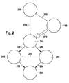
- a block diagram of an occupant protection system 110 of a vehicle 100 is shown, which comprises the holding device according to an embodiment of the present invention.
- the occupant protection system 110 includes, for example, a plurality of sensors for detecting an environmental situation provided, for example, as a radar sensor 120 for detecting an approach of a foreign vehicle or an acceleration sensor 130 for detecting a shock in an impact of the foreign vehicle on the (ego) vehicle 100.
- the signals of the two sensors 120 and 130 can be processed in an evaluation unit 140 or a control unit, which then activates the corresponding security means.
- a front airbag 150 in a steering wheel or instruments console of the vehicle 100, a side airbag 160 in a door or the seat of the vehicle 100 or a head airbag 170 in a roof rail of the vehicle 100 are triggered to prevent an impact of the vehicle occupant 180 on corresponding structural elements of the vehicle 100.
- a retaining device 195 described in more detail below can be activated, which is extended laterally toward the vehicle seat 190 and keeps the vehicle occupant 180 in an optimal position for the airbags 150, 160 and 170, thus keeping the vehicle occupant 180 as centrally and optimally aligned in the appropriate inflated the airbags falls and lateral slipping can be avoided by the corresponding airbags.
- the holding device 195 may be implemented in the form of a vehicle seat side cheek in seat and back, which is extended to the own vehicle before the actual impact of a foreign vehicle, so that the lateral lateral support of the occupant 180 is improved.
- the corresponding accident signals come in addition to the in FIG. 1 shown sensors 120 and 130 even more sensors into consideration, for example, the environment detection radar, video, stereo video, range video (PMD / Time of Flight) use ultrasound or Lidar. He is also a triggering of the holding device by a reversible actuator based on an inertial sensor and a vehicle dynamics sensors very beneficial.
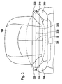
- the retaining means As the retaining means, the seat and a seat belt 200, a torso airbag, a head airbag and the ESA or holding device 195 are provided.
- the introduction of the holding device 195 is supported by the belt 200 (arrow 205) and very strongly inhibits (arrow 210) a lateral occupant movement 215 to the impact side of the foreign vehicle.
- the belt 200 inhibits, in a certain way, but not so much, the lateral Occupant movements 215, which is symbolized by the arrow 220.
- Such lateral occupant movements 215 would significantly reduce a survival zone 225, as indicated by the arrow 230 is symbolized.
- the lateral occupant motions 215 would also limit the effective effect of the airbag 235, particularly its effective volume (as indicated by arrow 240), but a large airbag 235 would increase the survival zone 225 (as indicated by arrow 245). However, a large survival zone 225 reduces the severity of injury 250 (corresponding to the interaction of arrow 255), and also a large airbag volume 235 reduces the corresponding severity severity 250 (corresponding to arrow 260).
- the introduction of the holding device 195 thus resulted in the inhibition of the lateral occupant movements to an improved protective effect by the other retaining means. Furthermore, there is the possibility that the holding device also allows an improvement of the effect of the side airbag, which then offers a larger effective volume.
- the concrete trajectory of the side cheek as a holding device especially in the aspects direction, way, angle of Anschmiegung and superposition of the translation with the pneumatic enclosure
- the way goes far beyond the typical way of the holding element according to the prior art and fixes the occupant in the vehicle seat.
- a detailed description of the design of the side cheek including the actuator and position sensors is described in the present case.
- a force limitation of the side cheek and a description of the interaction with the rest restraint system and an algorithm for dynamic adjustment of the total restraint system is described in the present case.
- the actuators of the holding device can be adapted by the occupant manually or else automatically or semi-automatically to the requirements of a comfortable driving.
- a driving dynamic lateral support or an active backrest width adjustment can be cited in known luxury vehicles, which can also be used in vehicle seats with the holding device.
- the sidewalls become 300 (as a holding element of the holding device) of the seat extended in a manner that the occupant is not pushed out of the seat, but rather undergoes an additional lateral support. The process takes place in one or more phases.
- the positioning unit 305 may be an electromotive or pneumatic unit that can move and adjust the holding members 300 in different directions.
- the side cheek 300 (or both side cheeks 300 either simultaneously or staggered) may be moved in a first direction 310 to subsequently be driven in a second direction 320 toward the occupant.
- actuators of the positioning unit 305 are basically all suitable machine elements individually or in combination conceivable as for example an electric motor with rack / cam, pneumatic cylinder and / or bubbles, spring elements with electromagnetic or other release mechanism.
- Fig. 3 be illustrated using the example of the seat side bolsters 300.
- the Fig. 3 also be interpreted to mean that the illustrated side cheeks 300 are side bolsters of a seat back of the vehicle seat (in a top view), the operation of the invention being similar in both scenarios.
- the center of gravity S of the upper body of a vehicle occupant is typically in conventional seats outside the effective restraint geometry in a special center of gravity area 330. It can be exploited here that the center of gravity S is located in a very narrow area above the vehicle seat surface for various people sitting in the vehicle seat, so that of a small centroid area 330 (the in Fig. 3 is shown as line 330) can be assumed. For example, this height of the center of gravity S of the occupant or the center of gravity in about 10 to 30 cm (but sometimes up to 60 cm) above the seat of the vehicle seat. The center of gravity S of the occupant may continue to lie in a distance range of 10 to 30 cm from the backrest of the vehicle seat.
- the prior art occupant is deemed insufficient (because the side cheek 300 extends only so far as to cover an area up to the mark 315).
- the occupant slides up the contour of a side cheek 300 or turns over it out of the seat 190.
- the side flank 300 is advanced further before the crash, so that it covers the center of gravity region 330 (as is apparent from FIG Fig. 3 is carried out after the execution of the second movement 320) is the upper body center of gravity S of the occupant within the effective retention geometry.
- the center of gravity can comprise an area in Fig. 3 between the solid lines below and above the center of gravity S; but can also be correspondingly smaller, and essentially the in Fig. 3 Dashed line 330 shown extends. If the sidewall 300 is set even steeper, the entire kinetic energy of the occupant can be absorbed and the upper body held in position.
- a belt with preferably a belt tensioner This restrains the occupants, so that the center of gravity S remains behind the retaining geometry of the side walls and in addition the friction between the occupant and seat back can reduce acceleration.
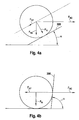
- a (crash resistant) angle ⁇ between side cheek surface 300 and seat (or backrest) greater than 45 ° is sought, as in Fig. 4a should be indicated.
- the lateral holding contour may also be advantageous to detect, for example by means of suitable (pressure) sensors or by measuring the increase in current in the electric motor, whether there is an increased resistance to the adjustment. In this way, the trapping of occupants or misuse could be detected and prevented.
- advantageously measures can also be taken to detect the adjustment path of the side cheeks. This is at the actuator e.g. by means of pressure sensor or Hall sensor possible or directly via capacitive or inductive displacement measurement, potentiometer or Endabscrien by force limitation, light barriers or reed contacts.
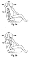
- Fig. 5 shows a further embodiment of the present invention as a holding device.
- the holding element 700 is provided in a starting position (see Fig. 5a ), which immediately before an accident from the backrest 190 by a positioning unit 710 is unfolded and the vehicle occupant 180 is an additional lateral support (see Fig. 5b ).
- the unfolding can be done by a realization of the device for improving the side support by means of a spring system 710 as a positioning unit.
- a spring system 710 as a positioning unit.
- the side wall 700 In the normal position ( Fig. 5a ), the side wall 700 is then in a comfortable position.
- Activating a preloaded spring after a trip signal causes sidewall 700 to extend ( Fig. 5b ).
- the adjustment of the holding element in the embodiments illustrated above after triggering the precrash status can be canceled at any time. If information is available to the system after the pre-crash status has been triggered to allow a safe statement that the expected crash does not occur, the adjustment process will be aborted and the side rail (s) will be returned to their initial state or a user-specified desired state brought. The longer the pre-warning time, the less certain is the crash or accident prediction. If the pre-crash status is set too fast and too early, false triggers occur, for example, from irreversible restraints. If such a false trip is detected by the system quickly enough and the adjustment process can be aborted, this reduces the impairment of the occupant due to false triggering. On the one hand, this leads to a higher acceptance of the system and, on the other hand, offers the possibility of increasing the early warning time without letting the negative effects of false triggering become too great.
- FIG. 1 shows a correlation diagram of said method 800 as an exemplary embodiment of the present invention.
- environment signals from an environment sensor 830 and other accident signals from another accident sensors 840 also the status 850 of the ESA or the holding device (for example, the position of the side cheek 300 or 700 or the degree of enclosure of the occupant) detected and included via a corresponding signal in the calculation or control 860 of the trigger signal 870, for example, for a belt tensioner or a side airbag.
- the present invention also includes a (according to Fig. 7 A method 900 for holding a vehicle occupant in a vehicle seat, wherein the center of gravity of the vehicle occupant is located in a predetermined center of gravity area above a vehicle seat surface when the occupant is seated on the vehicle seat and wherein the method includes the step of extending a retainer element 910 from a home position in a target position, in response to an activation signal, wherein the extension is made such that the holding member is brought to a target position laterally of the vehicle seat and wherein the holding member is disposed in the target position at a height above the vehicle seat surface, so that it in the target position Center of gravity at least partially covered laterally.
Landscapes
- Engineering & Computer Science (AREA)
- Mechanical Engineering (AREA)
- Aviation & Aerospace Engineering (AREA)
- Transportation (AREA)
- Seats For Vehicles (AREA)
Applications Claiming Priority (2)
| Application Number | Priority Date | Filing Date | Title |
|---|---|---|---|
| DE102009001426A DE102009001426A1 (de) | 2009-03-10 | 2009-03-10 | Haltevorrichtung und Verfahren zum Halten eines Fahrzeuginsassen in einem Fahrzeugsitz |
| PCT/EP2010/050189 WO2010102843A2 (de) | 2009-03-10 | 2010-01-11 | Haltevorrichtung und verfahren zum halten eines fahrzeuginsassen in einem fahrzeugsitz |
Publications (2)
| Publication Number | Publication Date |
|---|---|
| EP2406101A2 EP2406101A2 (de) | 2012-01-18 |
| EP2406101B1 true EP2406101B1 (de) | 2014-08-06 |
Family
ID=42111318
Family Applications (1)
| Application Number | Title | Priority Date | Filing Date |
|---|---|---|---|
| EP10701828.5A Not-in-force EP2406101B1 (de) | 2009-03-10 | 2010-01-11 | Haltevorrichtung und verfahren zum halten eines fahrzeuginsassen in einem fahrzeugsitz |
Country Status (6)
| Country | Link |
|---|---|
| US (1) | US20120089303A1 (enExample) |
| EP (1) | EP2406101B1 (enExample) |
| JP (1) | JP2012520196A (enExample) |
| CN (1) | CN102348575A (enExample) |
| DE (1) | DE102009001426A1 (enExample) |
| WO (1) | WO2010102843A2 (enExample) |
Families Citing this family (18)
| Publication number | Priority date | Publication date | Assignee | Title |
|---|---|---|---|---|
| DE102010003744A1 (de) * | 2010-04-08 | 2011-10-13 | Robert Bosch Gmbh | Verfahren und Steuergerät zum Steuern einer Insassenschutzvorrichtung eines Fahrzeugsitzes |
| DE102010031261A1 (de) | 2010-07-12 | 2012-01-12 | Robert Bosch Gmbh | Verfahren und Vorrichtung zum Schutz eines Fahrzeuginsassen bei einem Aufprall |
| DE102012206426B4 (de) | 2012-04-19 | 2020-10-15 | Robert Bosch Gmbh | Verfahren und Vorrichtung zum Schutz eines Fahrzeuginsassen bei einem Aufprall eines Objektes auf ein Fahrzeug |
| DE102013206508A1 (de) * | 2013-04-12 | 2014-10-16 | Robert Bosch Gmbh | Steuervorrichtung für eine Objektankopplungsvorrichtung eines Fahrzeugs, Objektankopplungsvorrichtung für ein Fahrzeug und Verfahren zum Dämpfen eines Aufpralls eines trägheitsbeschleunigten Objekts |
| JP6098460B2 (ja) * | 2013-09-20 | 2017-03-22 | トヨタ自動車株式会社 | 乗員保護装置 |
| US8985622B1 (en) * | 2014-01-10 | 2015-03-24 | Winnie Cannon | Personal protection assembly |
| US9457751B1 (en) * | 2015-03-31 | 2016-10-04 | Ford Global Technologies, Llc | Articulating support in a vehicle seat |
| US9505367B2 (en) * | 2015-03-31 | 2016-11-29 | Ford Global Technologies, Llc | Articulating support in a vehicle seat |
| DE102017100239A1 (de) * | 2016-01-25 | 2017-07-27 | Ford Global Technologies, Llc | Autonome auswahl von fahrzeugrückhaltemitteln |
| DE102016217105B4 (de) * | 2016-09-08 | 2025-04-30 | Robert Bosch Gmbh | Verfahren zum Ansteuern eines Insassenschutzsystems eines Fahrzeugs und Steuergerät |
| US10232814B2 (en) * | 2017-01-18 | 2019-03-19 | Toyota Motor Engineering & Manufacturing North America, Inc. | Inflatable vehicle occupant positioning system |
| JP6762328B2 (ja) * | 2018-02-14 | 2020-09-30 | オートリブ ディベロップメント エービー | 乗員拘束装置 |
| US20190275974A1 (en) * | 2018-03-12 | 2019-09-12 | Lear Corporation | Occupant protection systems for a vehicle seat |
| US10926733B2 (en) * | 2018-03-12 | 2021-02-23 | Ford Global Technologies, Llc | Vehicle including inflatable assembly supported by seat |
| CN112654527A (zh) | 2018-09-13 | 2021-04-13 | 沃尔沃卡车集团 | 商用车辆中的在撞击之后的动力学向后座椅滑动 |
| EP3849837A1 (en) * | 2018-09-13 | 2021-07-21 | Volvo Truck Corporation | Dynamic backward seat sliding before impact in a commercial vehicle |
| DE102019203033A1 (de) * | 2019-03-06 | 2020-09-10 | Audi Ag | Seitenairbaganordnung in einem Fahrzeugsitz |
| JP7235615B2 (ja) * | 2019-07-22 | 2023-03-08 | 株式会社Subaru | 乗員保護装置 |
Family Cites Families (15)
| Publication number | Priority date | Publication date | Assignee | Title |
|---|---|---|---|---|
| JPH0316452U (enExample) * | 1989-06-29 | 1991-02-19 | ||
| DE4305295B4 (de) * | 1992-03-04 | 2006-05-18 | Volkswagen Ag | Kraftfahrzeug mit einem Sitz, der zumindest eine zwischen einer Ruhestellung und einer Betriebsstellung bewegbare Seitenwange besitzt |
| JPH07117542A (ja) * | 1993-10-20 | 1995-05-09 | Mitsubishi Motors Corp | 車両用シ−トの乗員拘束装置 |
| JP2000511489A (ja) * | 1996-06-03 | 2000-09-05 | ユニヴァーサル プロパルション コムパニー インコーポレイテッド | 側面衝突エアバッグ装置 |
| DE10026444C2 (de) * | 2000-05-30 | 2002-04-04 | Autoliv Dev | Sicherheitsgurtsystem mit einer Messanordnung zur Bestimmung der Gurtbandkraft |
| DE10043290C1 (de) * | 2000-09-02 | 2002-04-18 | Acts Gmbh & Co Kg | Vorrichtung zum Schutz der Insassen eines Fahrzeuges bei einem Aufprall des Fahrzeuges auf ein Hindernis |
| US6871874B2 (en) * | 2002-12-18 | 2005-03-29 | Key Safety Systems, Inc. | Airbag deployment velocity sensor |
| DE10321871A1 (de) | 2003-05-15 | 2004-12-02 | Robert Bosch Gmbh | Insassenschutzsystem für Fahrzeuge und Verfahren zum Betätigen eines Insassenschutzsystems für Fahrzeuge |
| JP2006008026A (ja) * | 2004-06-28 | 2006-01-12 | Aisin Seiki Co Ltd | 車両の乗員保護装置 |
| JP2007001423A (ja) * | 2005-06-23 | 2007-01-11 | Toyota Motor Corp | 車両用乗員拘束制御装置 |
| FR2891213B1 (fr) * | 2005-09-26 | 2009-02-13 | Renault Sas | Siege de vehicule permettant de deplacer un occupant du siege en cas de choc. |
| DE102005062849A1 (de) * | 2005-12-23 | 2007-09-06 | Takata-Petri Ag | Insassenrückhalteeinrichtung für ein Kraftfahrzeug |
| JP2008126903A (ja) * | 2006-11-22 | 2008-06-05 | Aisin Seiki Co Ltd | 車両用シート装置 |
| FR2910853B1 (fr) * | 2006-12-29 | 2009-08-21 | Peugeot Citroen Automobiles Sa | Siege perfectionne pour vehicule automobile. |
| JP2008302804A (ja) * | 2007-06-07 | 2008-12-18 | Takata Corp | 乗員拘束装置 |
-
2009
- 2009-03-10 DE DE102009001426A patent/DE102009001426A1/de not_active Withdrawn
-
2010
- 2010-01-11 WO PCT/EP2010/050189 patent/WO2010102843A2/de not_active Ceased
- 2010-01-11 CN CN2010800115081A patent/CN102348575A/zh active Pending
- 2010-01-11 US US13/138,561 patent/US20120089303A1/en not_active Abandoned
- 2010-01-11 JP JP2011553368A patent/JP2012520196A/ja active Pending
- 2010-01-11 EP EP10701828.5A patent/EP2406101B1/de not_active Not-in-force
Also Published As
| Publication number | Publication date |
|---|---|
| CN102348575A (zh) | 2012-02-08 |
| WO2010102843A2 (de) | 2010-09-16 |
| JP2012520196A (ja) | 2012-09-06 |
| DE102009001426A1 (de) | 2010-09-16 |
| WO2010102843A3 (de) | 2010-12-23 |
| EP2406101A2 (de) | 2012-01-18 |
| US20120089303A1 (en) | 2012-04-12 |
Similar Documents
| Publication | Publication Date | Title |
|---|---|---|
| EP2406101B1 (de) | Haltevorrichtung und verfahren zum halten eines fahrzeuginsassen in einem fahrzeugsitz | |
| EP2346714B1 (de) | Fahrzeugsitz | |
| EP1838558B1 (de) | Sicherheitsanordnung | |
| DE102017103063B4 (de) | Insassenschutzvorrichtung | |
| DE102011012580B4 (de) | Verfahren und Vorrichtung zum Schutz von Insassen eines Fahrzeuges | |
| EP2552743B1 (de) | Verfahren und vorrichtung zum schützen und halten eines insassen sowie eine auswerte- und steuereinheit für eine schutz- und haltevorrichtung | |
| DE102015103081B4 (de) | Fahrzeuginsassenschutzvorrichtung | |
| DE102014223618A1 (de) | Verfahren zum Betreiben einer Sicherheitsvorrichtung eines Kraftfahrzeugs | |
| DE102015223313A1 (de) | Verfahren zum steuern eines beifahrer-airbags und beifahrer-airbag-system, das dieses anwendet | |
| DE102004038167A1 (de) | Kraftfahrzeug mit einem präventiv wirkenden Schutzsystem | |
| DE102008042020A1 (de) | Gurtsystem für ein Insassenschutzsystem in einem Fahrzeug | |
| DE102004058034A1 (de) | Aktives Kniepolster mit adaptivem Kraftreaktionssystem und -verfahren | |
| DE4440258C2 (de) | Sicherheitseinrichtung für einen Insassen eines Fahrzeugs | |
| DE102010054743A1 (de) | Sicherheitseinrichtung in einem Kraftfahrzeug | |
| DE102014000842B4 (de) | Verfahren zum Steuern einer Personen-Rückhalteeinrichtung eines Sicherheitssystems eines Fahrzeugs | |
| DE10224831B4 (de) | Kraftfahrzeug und Verfahren zur Reduzierung der Belastung von Insassen eines Kraftfahrzeugs bei einem Zusammenstoss mit einem Hindernis | |
| WO2006058718A1 (de) | Verfahren für ein präventiv wirkendes schutzsystem in einem kraftfahrzeug mit einer abstandssensorik | |
| DE102009001209B4 (de) | Verfahren und Steuergerät zur Ansteuerung eines reversiblen Personenrückhaltemittels auf einer aufprallabgewandten Seite eines Fahrzeugs | |
| DE102004012548B3 (de) | Insassenschutzvorrichtung und Verfahren zum Auslösen einer Insassenschutzvorrichtung | |
| DE10037220B4 (de) | Verfahren und Einrichtung zur situationsgerechten Ansteuerung | |
| DE10058430C2 (de) | Ausfahrbare Rückhalteeinrichtung | |
| DE102012206426B4 (de) | Verfahren und Vorrichtung zum Schutz eines Fahrzeuginsassen bei einem Aufprall eines Objektes auf ein Fahrzeug | |
| EP2036778B1 (de) | Verfahren zur von der sitzposition einer person abhängigen ansteuerung irreversibler rückhaltemittel | |
| DE102020213696A1 (de) | Vorrichtung und ein Verfahren zur Dämpfung einer Bewegung einer Sitzkomponente im Kraftfahrzeug | |
| DE202004008985U1 (de) | Rückhaltesystem für einen Fahrzeuginsassen |
Legal Events
| Date | Code | Title | Description |
|---|---|---|---|
| PUAI | Public reference made under article 153(3) epc to a published international application that has entered the european phase |
Free format text: ORIGINAL CODE: 0009012 |
|
| 17P | Request for examination filed |
Effective date: 20111010 |
|
| AK | Designated contracting states |
Kind code of ref document: A2 Designated state(s): AT BE BG CH CY CZ DE DK EE ES FI FR GB GR HR HU IE IS IT LI LT LU LV MC MK MT NL NO PL PT RO SE SI SK SM TR |
|
| DAX | Request for extension of the european patent (deleted) | ||
| 17Q | First examination report despatched |
Effective date: 20120709 |
|
| GRAP | Despatch of communication of intention to grant a patent |
Free format text: ORIGINAL CODE: EPIDOSNIGR1 |
|
| INTG | Intention to grant announced |
Effective date: 20140430 |
|
| GRAS | Grant fee paid |
Free format text: ORIGINAL CODE: EPIDOSNIGR3 |
|
| GRAA | (expected) grant |
Free format text: ORIGINAL CODE: 0009210 |
|
| AK | Designated contracting states |
Kind code of ref document: B1 Designated state(s): AT BE BG CH CY CZ DE DK EE ES FI FR GB GR HR HU IE IS IT LI LT LU LV MC MK MT NL NO PL PT RO SE SI SK SM TR |
|
| REG | Reference to a national code |
Ref country code: GB Ref legal event code: FG4D Free format text: NOT ENGLISH |
|
| REG | Reference to a national code |
Ref country code: CH Ref legal event code: EP Ref country code: AT Ref legal event code: REF Ref document number: 680861 Country of ref document: AT Kind code of ref document: T Effective date: 20140815 |
|
| REG | Reference to a national code |
Ref country code: IE Ref legal event code: FG4D Free format text: LANGUAGE OF EP DOCUMENT: GERMAN |
|
| REG | Reference to a national code |
Ref country code: DE Ref legal event code: R096 Ref document number: 502010007598 Country of ref document: DE Effective date: 20140918 |
|
| REG | Reference to a national code |
Ref country code: NL Ref legal event code: VDEP Effective date: 20140806 |
|
| REG | Reference to a national code |
Ref country code: LT Ref legal event code: MG4D |
|
| PG25 | Lapsed in a contracting state [announced via postgrant information from national office to epo] |
Ref country code: NO Free format text: LAPSE BECAUSE OF FAILURE TO SUBMIT A TRANSLATION OF THE DESCRIPTION OR TO PAY THE FEE WITHIN THE PRESCRIBED TIME-LIMIT Effective date: 20141106 Ref country code: BG Free format text: LAPSE BECAUSE OF FAILURE TO SUBMIT A TRANSLATION OF THE DESCRIPTION OR TO PAY THE FEE WITHIN THE PRESCRIBED TIME-LIMIT Effective date: 20141106 Ref country code: GR Free format text: LAPSE BECAUSE OF FAILURE TO SUBMIT A TRANSLATION OF THE DESCRIPTION OR TO PAY THE FEE WITHIN THE PRESCRIBED TIME-LIMIT Effective date: 20141107 Ref country code: FI Free format text: LAPSE BECAUSE OF FAILURE TO SUBMIT A TRANSLATION OF THE DESCRIPTION OR TO PAY THE FEE WITHIN THE PRESCRIBED TIME-LIMIT Effective date: 20140806 Ref country code: PT Free format text: LAPSE BECAUSE OF FAILURE TO SUBMIT A TRANSLATION OF THE DESCRIPTION OR TO PAY THE FEE WITHIN THE PRESCRIBED TIME-LIMIT Effective date: 20141209 Ref country code: ES Free format text: LAPSE BECAUSE OF FAILURE TO SUBMIT A TRANSLATION OF THE DESCRIPTION OR TO PAY THE FEE WITHIN THE PRESCRIBED TIME-LIMIT Effective date: 20140806 Ref country code: LT Free format text: LAPSE BECAUSE OF FAILURE TO SUBMIT A TRANSLATION OF THE DESCRIPTION OR TO PAY THE FEE WITHIN THE PRESCRIBED TIME-LIMIT Effective date: 20140806 Ref country code: SE Free format text: LAPSE BECAUSE OF FAILURE TO SUBMIT A TRANSLATION OF THE DESCRIPTION OR TO PAY THE FEE WITHIN THE PRESCRIBED TIME-LIMIT Effective date: 20140806 |
|
| PG25 | Lapsed in a contracting state [announced via postgrant information from national office to epo] |
Ref country code: HR Free format text: LAPSE BECAUSE OF FAILURE TO SUBMIT A TRANSLATION OF THE DESCRIPTION OR TO PAY THE FEE WITHIN THE PRESCRIBED TIME-LIMIT Effective date: 20140806 Ref country code: LV Free format text: LAPSE BECAUSE OF FAILURE TO SUBMIT A TRANSLATION OF THE DESCRIPTION OR TO PAY THE FEE WITHIN THE PRESCRIBED TIME-LIMIT Effective date: 20140806 Ref country code: PL Free format text: LAPSE BECAUSE OF FAILURE TO SUBMIT A TRANSLATION OF THE DESCRIPTION OR TO PAY THE FEE WITHIN THE PRESCRIBED TIME-LIMIT Effective date: 20140806 Ref country code: NL Free format text: LAPSE BECAUSE OF FAILURE TO SUBMIT A TRANSLATION OF THE DESCRIPTION OR TO PAY THE FEE WITHIN THE PRESCRIBED TIME-LIMIT Effective date: 20140806 Ref country code: CY Free format text: LAPSE BECAUSE OF FAILURE TO SUBMIT A TRANSLATION OF THE DESCRIPTION OR TO PAY THE FEE WITHIN THE PRESCRIBED TIME-LIMIT Effective date: 20140806 Ref country code: IS Free format text: LAPSE BECAUSE OF FAILURE TO SUBMIT A TRANSLATION OF THE DESCRIPTION OR TO PAY THE FEE WITHIN THE PRESCRIBED TIME-LIMIT Effective date: 20141206 |
|
| PG25 | Lapsed in a contracting state [announced via postgrant information from national office to epo] |
Ref country code: SK Free format text: LAPSE BECAUSE OF FAILURE TO SUBMIT A TRANSLATION OF THE DESCRIPTION OR TO PAY THE FEE WITHIN THE PRESCRIBED TIME-LIMIT Effective date: 20140806 Ref country code: CZ Free format text: LAPSE BECAUSE OF FAILURE TO SUBMIT A TRANSLATION OF THE DESCRIPTION OR TO PAY THE FEE WITHIN THE PRESCRIBED TIME-LIMIT Effective date: 20140806 Ref country code: EE Free format text: LAPSE BECAUSE OF FAILURE TO SUBMIT A TRANSLATION OF THE DESCRIPTION OR TO PAY THE FEE WITHIN THE PRESCRIBED TIME-LIMIT Effective date: 20140806 Ref country code: DK Free format text: LAPSE BECAUSE OF FAILURE TO SUBMIT A TRANSLATION OF THE DESCRIPTION OR TO PAY THE FEE WITHIN THE PRESCRIBED TIME-LIMIT Effective date: 20140806 Ref country code: IT Free format text: LAPSE BECAUSE OF FAILURE TO SUBMIT A TRANSLATION OF THE DESCRIPTION OR TO PAY THE FEE WITHIN THE PRESCRIBED TIME-LIMIT Effective date: 20140806 Ref country code: RO Free format text: LAPSE BECAUSE OF FAILURE TO SUBMIT A TRANSLATION OF THE DESCRIPTION OR TO PAY THE FEE WITHIN THE PRESCRIBED TIME-LIMIT Effective date: 20140806 |
|
| REG | Reference to a national code |
Ref country code: DE Ref legal event code: R097 Ref document number: 502010007598 Country of ref document: DE |
|
| PLBE | No opposition filed within time limit |
Free format text: ORIGINAL CODE: 0009261 |
|
| STAA | Information on the status of an ep patent application or granted ep patent |
Free format text: STATUS: NO OPPOSITION FILED WITHIN TIME LIMIT |
|
| PG25 | Lapsed in a contracting state [announced via postgrant information from national office to epo] |
Ref country code: BE Free format text: LAPSE BECAUSE OF NON-PAYMENT OF DUE FEES Effective date: 20150131 |
|
| 26N | No opposition filed |
Effective date: 20150507 |
|
| REG | Reference to a national code |
Ref country code: CH Ref legal event code: PL |
|
| PG25 | Lapsed in a contracting state [announced via postgrant information from national office to epo] |
Ref country code: LU Free format text: LAPSE BECAUSE OF FAILURE TO SUBMIT A TRANSLATION OF THE DESCRIPTION OR TO PAY THE FEE WITHIN THE PRESCRIBED TIME-LIMIT Effective date: 20150111 |
|
| GBPC | Gb: european patent ceased through non-payment of renewal fee |
Effective date: 20150111 |
|
| PG25 | Lapsed in a contracting state [announced via postgrant information from national office to epo] |
Ref country code: MC Free format text: LAPSE BECAUSE OF FAILURE TO SUBMIT A TRANSLATION OF THE DESCRIPTION OR TO PAY THE FEE WITHIN THE PRESCRIBED TIME-LIMIT Effective date: 20140806 |
|
| PG25 | Lapsed in a contracting state [announced via postgrant information from national office to epo] |
Ref country code: CH Free format text: LAPSE BECAUSE OF NON-PAYMENT OF DUE FEES Effective date: 20150131 Ref country code: LI Free format text: LAPSE BECAUSE OF NON-PAYMENT OF DUE FEES Effective date: 20150131 Ref country code: GB Free format text: LAPSE BECAUSE OF NON-PAYMENT OF DUE FEES Effective date: 20150111 |
|
| REG | Reference to a national code |
Ref country code: IE Ref legal event code: MM4A |
|
| PG25 | Lapsed in a contracting state [announced via postgrant information from national office to epo] |
Ref country code: SI Free format text: LAPSE BECAUSE OF FAILURE TO SUBMIT A TRANSLATION OF THE DESCRIPTION OR TO PAY THE FEE WITHIN THE PRESCRIBED TIME-LIMIT Effective date: 20140806 |
|
| REG | Reference to a national code |
Ref country code: FR Ref legal event code: PLFP Year of fee payment: 7 |
|
| PG25 | Lapsed in a contracting state [announced via postgrant information from national office to epo] |
Ref country code: IE Free format text: LAPSE BECAUSE OF NON-PAYMENT OF DUE FEES Effective date: 20150111 |
|
| REG | Reference to a national code |
Ref country code: AT Ref legal event code: MM01 Ref document number: 680861 Country of ref document: AT Kind code of ref document: T Effective date: 20150111 |
|
| PG25 | Lapsed in a contracting state [announced via postgrant information from national office to epo] |
Ref country code: AT Free format text: LAPSE BECAUSE OF NON-PAYMENT OF DUE FEES Effective date: 20150111 |
|
| REG | Reference to a national code |
Ref country code: DE Ref legal event code: R084 Ref document number: 502010007598 Country of ref document: DE |
|
| PG25 | Lapsed in a contracting state [announced via postgrant information from national office to epo] |
Ref country code: MT Free format text: LAPSE BECAUSE OF FAILURE TO SUBMIT A TRANSLATION OF THE DESCRIPTION OR TO PAY THE FEE WITHIN THE PRESCRIBED TIME-LIMIT Effective date: 20140806 |
|
| REG | Reference to a national code |
Ref country code: FR Ref legal event code: PLFP Year of fee payment: 8 |
|
| PG25 | Lapsed in a contracting state [announced via postgrant information from national office to epo] |
Ref country code: SM Free format text: LAPSE BECAUSE OF FAILURE TO SUBMIT A TRANSLATION OF THE DESCRIPTION OR TO PAY THE FEE WITHIN THE PRESCRIBED TIME-LIMIT Effective date: 20140806 Ref country code: HU Free format text: LAPSE BECAUSE OF FAILURE TO SUBMIT A TRANSLATION OF THE DESCRIPTION OR TO PAY THE FEE WITHIN THE PRESCRIBED TIME-LIMIT; INVALID AB INITIO Effective date: 20100111 |
|
| PG25 | Lapsed in a contracting state [announced via postgrant information from national office to epo] |
Ref country code: TR Free format text: LAPSE BECAUSE OF FAILURE TO SUBMIT A TRANSLATION OF THE DESCRIPTION OR TO PAY THE FEE WITHIN THE PRESCRIBED TIME-LIMIT Effective date: 20140806 |
|
| REG | Reference to a national code |
Ref country code: FR Ref legal event code: PLFP Year of fee payment: 9 |
|
| PG25 | Lapsed in a contracting state [announced via postgrant information from national office to epo] |
Ref country code: MK Free format text: LAPSE BECAUSE OF FAILURE TO SUBMIT A TRANSLATION OF THE DESCRIPTION OR TO PAY THE FEE WITHIN THE PRESCRIBED TIME-LIMIT Effective date: 20140806 |
|
| PGFP | Annual fee paid to national office [announced via postgrant information from national office to epo] |
Ref country code: FR Payment date: 20190122 Year of fee payment: 10 Ref country code: DE Payment date: 20190326 Year of fee payment: 10 |
|
| REG | Reference to a national code |
Ref country code: DE Ref legal event code: R119 Ref document number: 502010007598 Country of ref document: DE |
|
| PG25 | Lapsed in a contracting state [announced via postgrant information from national office to epo] |
Ref country code: DE Free format text: LAPSE BECAUSE OF NON-PAYMENT OF DUE FEES Effective date: 20200801 Ref country code: FR Free format text: LAPSE BECAUSE OF NON-PAYMENT OF DUE FEES Effective date: 20200131 |