EP2405201B1 - Injection nozzle for a turbomachine - Google Patents
Injection nozzle for a turbomachine Download PDFInfo
- Publication number
- EP2405201B1 EP2405201B1 EP11173161.8A EP11173161A EP2405201B1 EP 2405201 B1 EP2405201 B1 EP 2405201B1 EP 11173161 A EP11173161 A EP 11173161A EP 2405201 B1 EP2405201 B1 EP 2405201B1
- Authority
- EP
- European Patent Office
- Prior art keywords
- injection nozzle
- tube elements
- nozzle assembly
- row
- turbomachine
- Prior art date
- Legal status (The legal status is an assumption and is not a legal conclusion. Google has not performed a legal analysis and makes no representation as to the accuracy of the status listed.)
- Active
Links
- 238000002347 injection Methods 0.000 title claims description 68
- 239000007924 injection Substances 0.000 title claims description 68
- 239000000446 fuel Substances 0.000 claims description 44
- 239000012530 fluid Substances 0.000 claims 1
- 238000002485 combustion reaction Methods 0.000 description 27
- MWUXSHHQAYIFBG-UHFFFAOYSA-N Nitric oxide Chemical compound O=[N] MWUXSHHQAYIFBG-UHFFFAOYSA-N 0.000 description 15
- 238000002156 mixing Methods 0.000 description 14
- 239000007789 gas Substances 0.000 description 13
- 238000011144 upstream manufacturing Methods 0.000 description 9
- 230000000712 assembly Effects 0.000 description 8
- 238000000429 assembly Methods 0.000 description 8
- 239000000203 mixture Substances 0.000 description 6
- UFHFLCQGNIYNRP-UHFFFAOYSA-N Hydrogen Chemical compound [H][H] UFHFLCQGNIYNRP-UHFFFAOYSA-N 0.000 description 5
- 239000000567 combustion gas Substances 0.000 description 5
- 239000001257 hydrogen Substances 0.000 description 5
- 229910052739 hydrogen Inorganic materials 0.000 description 5
- 230000006641 stabilisation Effects 0.000 description 3
- 238000011105 stabilization Methods 0.000 description 3
- 230000007704 transition Effects 0.000 description 3
- 238000004873 anchoring Methods 0.000 description 2
- 238000004891 communication Methods 0.000 description 2
- 230000033228 biological regulation Effects 0.000 description 1
- 238000010276 construction Methods 0.000 description 1
- 238000001816 cooling Methods 0.000 description 1
- 238000009792 diffusion process Methods 0.000 description 1
- 238000000034 method Methods 0.000 description 1
- 239000007800 oxidant agent Substances 0.000 description 1
- 230000035515 penetration Effects 0.000 description 1
Images


Classifications
-
- F—MECHANICAL ENGINEERING; LIGHTING; HEATING; WEAPONS; BLASTING
- F23—COMBUSTION APPARATUS; COMBUSTION PROCESSES
- F23R—GENERATING COMBUSTION PRODUCTS OF HIGH PRESSURE OR HIGH VELOCITY, e.g. GAS-TURBINE COMBUSTION CHAMBERS
- F23R3/00—Continuous combustion chambers using liquid or gaseous fuel
- F23R3/28—Continuous combustion chambers using liquid or gaseous fuel characterised by the fuel supply
-
- F—MECHANICAL ENGINEERING; LIGHTING; HEATING; WEAPONS; BLASTING
- F23—COMBUSTION APPARATUS; COMBUSTION PROCESSES
- F23D—BURNERS
- F23D14/00—Burners for combustion of a gas, e.g. of a gas stored under pressure as a liquid
- F23D14/46—Details, e.g. noise reduction means
- F23D14/62—Mixing devices; Mixing tubes
-
- F—MECHANICAL ENGINEERING; LIGHTING; HEATING; WEAPONS; BLASTING
- F23—COMBUSTION APPARATUS; COMBUSTION PROCESSES
- F23D—BURNERS
- F23D14/00—Burners for combustion of a gas, e.g. of a gas stored under pressure as a liquid
- F23D14/46—Details, e.g. noise reduction means
- F23D14/72—Safety devices, e.g. operative in case of failure of gas supply
- F23D14/82—Preventing flashback or blowback
-
- F—MECHANICAL ENGINEERING; LIGHTING; HEATING; WEAPONS; BLASTING
- F23—COMBUSTION APPARATUS; COMBUSTION PROCESSES
- F23G—CREMATION FURNACES; CONSUMING WASTE PRODUCTS BY COMBUSTION
- F23G2900/00—Special features of, or arrangements for incinerators
- F23G2900/54402—Injecting fluid waste into incinerator
-
- F—MECHANICAL ENGINEERING; LIGHTING; HEATING; WEAPONS; BLASTING
- F23—COMBUSTION APPARATUS; COMBUSTION PROCESSES
- F23R—GENERATING COMBUSTION PRODUCTS OF HIGH PRESSURE OR HIGH VELOCITY, e.g. GAS-TURBINE COMBUSTION CHAMBERS
- F23R2900/00—Special features of, or arrangements for continuous combustion chambers; Combustion processes therefor
- F23R2900/00002—Gas turbine combustors adapted for fuels having low heating value [LHV]
Definitions
- the subject matter disclosed herein relates to the art of turbomachines and, more particularly, to an injection nozzle for a turbomachine.
- gas turbine engines combust a fuel/air mixture that releases heat energy to form a high temperature gas stream.
- the high temperature gas stream is channeled to a turbine via a hot gas path.
- the turbine converts thermal energy from the high temperature gas stream to mechanical energy that rotates a turbine shaft.
- the turbine may be used in a variety of applications, such as for providing power to a pump or an electrical generator.
- NOx nitrogen oxide
- One method of achieving low NOx levels is to ensure good mixing of fuel and air prior to combustion.
- fuel jet penetration is not sufficient to mix with available air. As such fuel will flow through a boundary layer in a premixer tube portion of the injector. This fuel behavior results in a flashback condition that limits an overall operational range of the turbomachine.
- US 4100733 describes an apparatus for supplying fuel to the combustion chamber of a gas turbine engine, where axially extending tubes are used for premixing gaseous or vaporized fuel with air in the supply means upstream of the combustion chamber.
- US 2004/000146 describes a gas turbine combustor having a combustion chamber wherein fuel and air are supplied thereinto as a plurality of coaxial jets.
- US 6267585 describes a plate burner for combusting hydrogen with air as an oxidizer forms a wall portion of a combustion chamber of a gas turbine.
- the plate burner is constructed that air and hydrogen are separately guided to the downstream surface area facing into the combustion chamber for forming a large number of diffusive microcombustion flames, thus achieving a very low mixing scale simultaneously with a high nixing intensity.
- the hydrogen enters the entrance area into the combustion chamber either through a porous wall, and air is injected into the hydrogen environment to form inverse diffusive microcombustion flames or the hydrogen is injected through a multitude of fine holes into high velocity air jets forming regular diffusion flames.
- the present invention resides in a turbomachine as defined in claim 1 of the appended claims.
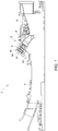
- turbomachine 2 constructed in accordance with exemplary embodiments is indicated generally at 2.
- Turbomachine 2 includes a compressor 4 and a combustor assembly 5 having at least one combustor 6 provided with a fuel nozzle or injector assembly housing 8.
- Turbomachine 2 also includes a turbine 10.
- turbomachine 2 is a heavy duty gas turbine engine, however, it should be understood that the exemplary embodiments are not limited to any one particular engine configuration and may be used in connection with a variety of other gas turbine engines.
- combustor 6 is coupled in flow communication with compressor 4 and turbine 10.
- Compressor 4 includes a diffuser 22 and a compressor discharge plenum 24 that are coupled in flow communication with each other.
- Combustor 6 also includes an end cover 30 positioned at a first end thereof. As will be discussed more fully below, end cover 30 supports a plurality of injection nozzle assemblies, three of which are indicated at 38-40.
- Combustor 6 further includes a combustor casing 44 and a combustor liner 46. As shown, combustor liner 46 is positioned radially inward from combustor casing 44 so as to define a combustion chamber 48.
- An annular combustion chamber cooling passage 49 is defined between combustor casing 44 and combustor liner 46.
- a transition piece 55 couples combustor 6 to turbine 10. Transition piece 55 channels combustion gases generated in combustion chamber 48 downstream towards a first stage turbine nozzle (not shown). Towards that end, transition piece 55 includes an inner wall 64 and an outer wall 65. Outer wall 65 includes a plurality of openings 66 that lead to an annular passage 68 defined between inner wall 64 and outer wall 65. Inner wall 64 defines a guide cavity 72 that extends between combustion chamber 48 and turbine 10.
- combustor 6 may include additional injector nozzle assemblies (not shown) and turbomachine 2 may include additional combustors (also not shown).
- the combustible mixture is channeled to combustion chamber 48 and ignited to form combustion gases. The combustion gases are then channeled to turbine 10. Thermal energy from the combustion gases is converted to mechanical, rotational energy.
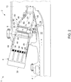
- injection nozzle assembly 38 includes a first end portion or fuel inlet 80 that extends to a second end portion or circumferential wall 82 through a plenum 84 having an end wall 86.
- Injection nozzle assembly 38 also includes a plurality of tube elements, one of which is indicated generally at 90, arranged in a number of rows that extend radially about circumferential wall 82.
- tube elements 90 receive fuel from a fuel inlet tube 100 that extends through injection nozzle assembly 38 from end cover 30 ( FIG. 2 ), to a conduit 120, and then on to a central receiving port 124.
- upstream fuel delivery plenum 128 is defined by a gap that exists between adjacent tube elements 90.
- the fuel cools down circumferential wall 82 and removes heat from the plurality of tube elements 90. Heat removal is desirable due to the high H2 flame anchoring generally very close to circumferential wall 82 and raising temperatures of the plurality of tube elements 90. Accordingly, the exemplary embodiments improve the flashback margin by lowering temperatures at circumferential wall 82 and the plurality of tube elements 90.
- tube elements 90 include a body 130 having a first end section or inlet 132 that extends from end wall 86, to a second end section or outlet 134 through an intermediate section 135.
- Intermediate section 135 includes an opening (not shown) that fluidly connects tube elements 90 with upstream fuel delivery plenum 128.
- Outlet 134 extends beyond circumferential wall 82 of injection nozzle assembly 38 thereby defining an interface zone 143.
- outlet 134 extends between about 0.1D to about 1.2D (where D is an inner diameter of tube element 90) from circumferential wall 82.
- interface zone 143 is defined by a substantially perpendicular angle between circumferential wall 82 and outlet 134. Extending outlet 134 beyond circumferential wall 82, enables injection nozzle assembly 38 to not only achieve a more complete mixing of fuel and air thereby creating a more stable flame which, in turn, leads to more complete combustion, but also reduces occurrences of flash back. That is, the projecting end portions of tube elements 90 create flow vortices that enhance mixing. The enhanced mixing leads to more complete combustion resulting in lower emissions. The enhanced mixing also substantially limits flashback.
- extending outlet 134 beyond circumferential wall 82 forms a mixing region (not separately labeled) at interface zone 143.
- turbomachine 2 can be operated in a lower turn down mode.
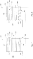
- injection nozzle assembly 160 includes a first end portion (not shown) that extends to a second end portion or circumferential wall 166 through a plenum (not shown) having an end wall 170.
- injection nozzle assembly 160 also includes a plurality of tube elements, one of which is indicated generally at 175, arranged in a number of rows (not shown) that extend radially about circumferential wall 166.
- Tube elements 175 include a body 196 having a first end section or inlet 198 that extends from end wall 170, to a second end section or outlet 200 through an intermediate section 202.
- Intermediate section 202 includes an opening (not shown) that fluidly connects tube elements 175 with an upstream fuel delivery plenum (not shown).
- Outlet 200 extends beyond circumferential wall 166 of injection nozzle assembly 160 thereby defining an interface zone 209. In accordance with one aspect of the exemplary embodiment, outlet 200 extends between about 0.1D to about 1.2D (where D is an inner diameter of tube element 175) from circumferential wall 166.
- interface zone 209 is defined by a substantially sloping junction between circumferential wall 166 and outlet 200. More specifically, in the exemplary embodiment shown, circumferential wall 166 includes a substantially planar surface with interface zone 209 creating a gradually sloping connection to outlet 200 of tube elements 175. In a manner similar to that described above, extending outlet 200 beyond circumferential wall 166 enables injection nozzle assembly 160 to not only achieve a more complete mixing of fuel and air thereby creating a more stable flame which, leads to more complete combustion, but also reduces occurrences of flash back. That is, the projecting end portions of tube elements 175 create flow vortices that enhance mixing. The enhanced mixing leads to more complete combustion resulting in lower emissions, and prevents flashback. By eliminating or reducing the probability of flashback, turbomachine 2 can be operated in a lower turn down mode.
- Injection nozzle assembly 220 includes a first end portion (not shown) that extends to a second end portion or circumferential wall 224 through an internal plenum (not shown) having an end wall 228.
- Injection nozzle assembly 220 also includes a plurality of tube elements, one of which is indicated generally at 230 that are arranged in a number of rows (not shown) that extend radially about circumferential wall 224.
- tube elements 230 include a body 243 having a first end section or inlet 244 that extends from end wall 228, to a second end section or outlet 245 through an intermediate section 246.
- Intermediate section 246 includes an opening (not shown) that fluidly connects tube element 230 with upstream fuel delivery plenum (also not shown).
- Second end section 245 extends beyond circumferential wall 224 of injection nozzle assembly 220 thereby defining an interface zone 250.
- outlet 245 extends between about 0.1D to about 1.2D (where D is an inner diameter of tube element 230) from circumferential wall 224.
- interface zone 250 is defined by a substantially sloping junction between circumferential wall 224 and outlet 245. More specifically, in the exemplary embodiment shown, circumferential wall 224 includes a dimpled surface, e.g., a surface having a plurality of dimples or recessed regions 255 that are present at interstitial regions between each of the plurality of tubes elements 230. In this manner, interface zone 250 creates a gradually sloping connection to outlet 245 of tube element 230.
- outlet 245 beyond circumferential wall 224 enables injection nozzle assembly 220 to not only achieve a more complete mixing of fuel and air thereby creating a more stable flame which, in turn, leads to more complete combustion, but also reduces occurrences of flash back.
- the addition of the plurality of recessed regions about each of the plurality of tube elements provides enhanced fuel circulation that leads to a gradually leaner fuel distribution in a boundary layer region at circumferential wall 224.
- the leaner fuel distribution further reduces the possibility of flashback at injection nozzle assembly 220.
- the fuel cools down circumferential wall 224 and removes heat from the plurality of tube elements 230 through fins (not shown). Heat removal is desirable due to the high H2 flame anchoring generally very close to circumferential wall 224 and raising temperatures of the plurality of tube elements 230. Accordingly, the exemplary embodiments improve flashback margin by lowering temperatures at circumferential wall 224 and the plurality of tube elements 230.
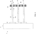
- Injection nozzle assembly 320 includes a first end portion (not shown) that extends to a second end portion or circumferential wall 324 through an internal plenum 326 having an end wall 328.
- Injection nozzle assembly 320 also includes a plurality of tube elements, one of which is indicated generally at 330, arranged in a number of rows that extend radially about circumferential wall 324.
- tube elements 330 receive fuel from a fuel inlet tube (not shown) that extends through injection nozzle assembly 320 from end cover 30 ( FIG. 2 ) to a central receiving port (also not shown).
- Tube elements 330 include a body 343 having a first end section or inlet 344 that extends from end wall 328, to a second end section or outlet 345 through an intermediate section 346.
- Intermediate section 346 includes an opening (not shown) that fluidly connects tube elements 330 with upstream fuel delivery plenum (also not shown).
- Outlet 345 extends beyond circumferential wall 324 of injection nozzle assembly 320 thereby defining an interface zone 350.
- outlet 345 extends between about 0.1D to about 1.2D (where D is an inner diameter of tube element 330) from circumferential wall 324.
- interface zone 350 is defined by a substantially perpendicular angle between circumferential wall 324 and outlet 345. In this manner, interface zone 350 establishes a connection with second end section 324 of tube element 330. In a manner also similar to that described above, by extending outlet 345 beyond circumferential wall 324 enables injection nozzle assembly 320 to not only achieves a more complete mixing of fuel and air thereby creating a more stable flame which, in turn, leads to more complete combustion, but also reduces occurrences of flash back.
- injection nozzle assembly 320 includes a plurality of angled tube elements, one of which is indicated generally at 360 arranged in an inner one of the plurality of rows (not separately labeled).
- Tube elements 360 include an angled region 365. Angled region 365 creates a centralized flame stabilization zone and a leaner flame at first and second rows (not separately labeled) of tube elements 330 in combustion chamber 48 ( FIG. 2 ), which further enhances flame stability leading to more complete combustion and lower emissions.
- injection nozzle assembly 320 includes a plurality of angled tube elements 400 arranged in the inner most row (not separately labeled) that surrounds central receiving port (not shown). Angled tube elements 400 are angled from a first end section or inlet 402 to a second end section or outlet 404 relative to a longitudinal axis (not separately labeled) of injection nozzle assembly 320. In accordance with one aspect of the exemplary embodiment, angled tube elements 400 are at an angle of less than 20° relative to the longitudinal axis of injection nozzle assembly 320.
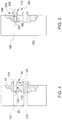
- Injection nozzle assembly 420 includes a first end portion (not shown) that extends to a second end portion or circumferential wall 424 through an internal plenum 426 having an end wall 428.
- Injection nozzle assembly 420 also includes a plurality of tube elements 430 arranged circumferentially about a central receiving port (not shown).
- Tube elements 430 include a first or inner most row 440 arranged about the central receiving port, a second row 442 arranged about first row 440, a third row 444 arranged about second row 442, and a fourth row 446 arranged about third row 444.
- Tube elements 430 in, for example third row 444 include a body 480 having a first end section or inlet 482 that extends from end wall 428, to a second end section or outlet 483 through an intermediate section 485.
- Intermediate section 485 includes an opening (not shown that fluidly connects tube elements 430 with upstream fuel delivery plenum (also not shown).
- Second end section 483 extends beyond second end portion 424 of injection nozzle assembly 420 thereby defining an interface zone 490.
- outlet 483 extends between about 0.1D to about 1.2D (where D is an inner diameter of tube element 430) from circumferential wall 424.
- the plurality of tube elements 430 arranged in first row 440 are positioned at a first angle relative to a centerline of injection nozzle assembly 420.
- tube elements 430 in first row 440 are at an angle of about 20°.
- the plurality of tube elements 430 arranged in second row 442 are arranged at a second angle, that is distinct from the first angle, relative to the centerline of injection nozzle assembly 420.
- tube elements 430 in second row 442 are at an angle of about 10°.
- first and second rows 440 and 442 creates a centralized flame stabilization zone and a leaner flame at the first, second and third rows 440, 442, and 444 in combustion chamber 48, which further enhances flame stability leading to more complete combustion and lower emissions.
- Injection nozzle assembly 520 includes a first end portion (not shown) that extends to a second end portion or circumferential wall 524 through an internal plenum 526 having an end wall 528.
- Injection nozzle assembly 520 also includes a plurality of tube elements 530 arranged circumferentially about a central receiving port (not shown).
- Tube elements 530 include a first or inner most row 540, a second row 542 arranged about first row 540, a third row 544 arranged about second row 542, and a fourth row 546 arranged about third row 544.
- row 546 include a body 580 having a first end section or inlet 582 that extends from end wall 528, to a second end section or outlet 583 through an intermediate section 585.
- Intermediate section 585 includes an opening (not shown) that fluidly connects tube elements 530 with upstream fuel delivery plenum (also not shown).
- Outlet 583 extends beyond second end portion 524 of injection nozzle assembly 520 thereby defining an interface zone 590. In accordance with one aspect of the exemplary embodiment, outlet 583 extends between about 0.1D to about 1.2D (where D is an inner diameter of tube element 530) from circumferential wall 524.
- the plurality of tube elements 530 arranged in first row 540 are positioned at a first angle relative to a centerline of injection nozzle assembly 520.
- tube elements 530 in first row 540 are at an angle of about 20°.
- the plurality of tube elements 530 arranged in second row 542 are arranged at a second angle, that is distinct from the first angle, relative to the centerline of injection nozzle assembly 520.
- tube elements 530 in second row 542 are at an angle of about 15°.
- the plurality of tube elements 530 arranged in third row 544 are arranged at a third angle that is distinct from the first and second angles, relative to the centerline of injection nozzle assembly 520. In accordance with the exemplary aspect shown, tube elements 530 in third row 544 are at an angle of about 10°.
- the plurality of tube elements 530 arranged in fourth row 546 are arranged at a fourth angle that is distinct from the first, second and third angles, relative to the centerline of injection nozzle assembly 520. In accordance with the exemplary aspect shown, tube elements 530 in fourth row 546 are at an angle of about 5°.
- first, second, third and fourth rows 440, 442, 444, and 446 creates a centralized flame stabilization zone and a leaner flame in combustion chamber 48, which further enhances flame stability leading to more complete combustion and lower emissions.
- the exemplary embodiments provide an injection nozzle assembly having tube elements that extend beyond a hot face of the injection nozzle. Extending the tube elements beyond the hot face not only achieves a more complete mixing of fuel and air but also reduces occurrences of flash back. More complete combustion leads to fewer NOx emissions while reducing flashback enables the turbomachine to be operated in a turn down mode that is lower than currently possible. In turn down, flow velocities are lower which tend to create flashback conditions.
Applications Claiming Priority (1)
| Application Number | Priority Date | Filing Date | Title |
|---|---|---|---|
| US12/832,330 US8261555B2 (en) | 2010-07-08 | 2010-07-08 | Injection nozzle for a turbomachine |
Publications (3)
| Publication Number | Publication Date |
|---|---|
| EP2405201A2 EP2405201A2 (en) | 2012-01-11 |
| EP2405201A3 EP2405201A3 (en) | 2012-04-25 |
| EP2405201B1 true EP2405201B1 (en) | 2017-10-25 |
Family
ID=44583987
Family Applications (1)
| Application Number | Title | Priority Date | Filing Date |
|---|---|---|---|
| EP11173161.8A Active EP2405201B1 (en) | 2010-07-08 | 2011-07-07 | Injection nozzle for a turbomachine |
Country Status (4)
| Country | Link |
|---|---|
| US (1) | US8261555B2 (ja) |
| EP (1) | EP2405201B1 (ja) |
| JP (1) | JP5860620B2 (ja) |
| CN (1) | CN102313299B (ja) |
Families Citing this family (27)
| Publication number | Priority date | Publication date | Assignee | Title |
|---|---|---|---|---|
| US8511092B2 (en) * | 2010-08-13 | 2013-08-20 | General Electric Company | Dimpled/grooved face on a fuel injection nozzle body for flame stabilization and related method |
| US8875516B2 (en) | 2011-02-04 | 2014-11-04 | General Electric Company | Turbine combustor configured for high-frequency dynamics mitigation and related method |
| US8511086B1 (en) * | 2012-03-01 | 2013-08-20 | General Electric Company | System and method for reducing combustion dynamics in a combustor |
| US9709277B2 (en) | 2012-05-15 | 2017-07-18 | General Electric Company | Fuel plenum premixing tube with surface treatment |
| US8904798B2 (en) | 2012-07-31 | 2014-12-09 | General Electric Company | Combustor |
| US9175855B2 (en) | 2012-10-29 | 2015-11-03 | General Electric Company | Combustion nozzle with floating aft plate |
| US9353950B2 (en) * | 2012-12-10 | 2016-05-31 | General Electric Company | System for reducing combustion dynamics and NOx in a combustor |
| WO2014141397A1 (ja) | 2013-03-13 | 2014-09-18 | 株式会社日立製作所 | ガスタービン燃焼器 |
| US9423135B2 (en) | 2013-11-21 | 2016-08-23 | General Electric Company | Combustor having mixing tube bundle with baffle arrangement for directing fuel |
| US9435540B2 (en) | 2013-12-11 | 2016-09-06 | General Electric Company | Fuel injector with premix pilot nozzle |
| US9664392B2 (en) * | 2013-12-13 | 2017-05-30 | General Electric Company | Bundled tube fuel injector with outer shroud and outer band connection |
| US9714767B2 (en) | 2014-11-26 | 2017-07-25 | General Electric Company | Premix fuel nozzle assembly |
| WO2016085494A1 (en) * | 2014-11-26 | 2016-06-02 | Siemens Aktiengesellschaft | Fuel lance with means for interacting with a flow of air and improve breakage of an ejected liquid jet of fuel |
| US10030869B2 (en) | 2014-11-26 | 2018-07-24 | General Electric Company | Premix fuel nozzle assembly |
| US9982892B2 (en) | 2015-04-16 | 2018-05-29 | General Electric Company | Fuel nozzle assembly including a pilot nozzle |
| US9803867B2 (en) * | 2015-04-21 | 2017-10-31 | General Electric Company | Premix pilot nozzle |
| US10584638B2 (en) * | 2016-03-25 | 2020-03-10 | General Electric Company | Turbine nozzle cooling with panel fuel injector |
| US11525578B2 (en) | 2017-08-16 | 2022-12-13 | General Electric Company | Dynamics-mitigating adapter for bundled tube fuel nozzle |
| KR20190040666A (ko) | 2017-10-11 | 2019-04-19 | 두산중공업 주식회사 | 연소기 및 이를 포함하는 가스 터빈 |
| KR102065725B1 (ko) | 2018-02-01 | 2020-02-17 | 두산중공업 주식회사 | 가스터빈 연소기의 스월 베인 |
| KR102065714B1 (ko) | 2018-02-01 | 2020-01-13 | 두산중공업 주식회사 | 가스터빈 연소기의 스월 베인 |
| KR102065723B1 (ko) | 2018-02-01 | 2020-01-13 | 두산중공업 주식회사 | 가스터빈 연소기의 스월 베인 |
| KR102095036B1 (ko) | 2018-02-01 | 2020-03-30 | 두산중공업 주식회사 | 가스터빈 연소기의 스월 베인 |
| EP3637000A1 (en) * | 2018-10-11 | 2020-04-15 | Siemens Aktiengesellschaft | Gas turbine burner for reactive fuels |
| WO2023204847A2 (en) * | 2021-11-03 | 2023-10-26 | Power Systems Mfg., Llc | Multitube pilot injector having an insulated manifold for a gas turbine engine |
| KR102583226B1 (ko) * | 2022-02-07 | 2023-09-25 | 두산에너빌리티 주식회사 | 다단 연료 공급부가 구비된 마이크로 믹서 및 이를 포함하는 가스 터빈 |
| KR102583225B1 (ko) | 2022-02-07 | 2023-09-25 | 두산에너빌리티 주식회사 | 마이크로 믹서 및 이를 포함하는 가스 터빈 |
Family Cites Families (16)
| Publication number | Priority date | Publication date | Assignee | Title |
|---|---|---|---|---|
| US4100733A (en) | 1976-10-04 | 1978-07-18 | United Technologies Corporation | Premix combustor |
| JPH05196232A (ja) * | 1991-08-01 | 1993-08-06 | General Electric Co <Ge> | 耐逆火性燃料ステージング式予混合燃焼器 |
| US6267585B1 (en) | 1995-12-19 | 2001-07-31 | Daimlerchrysler Aerospace Airbus Gmbh | Method and combustor for combusting hydrogen |
| DE19547506B4 (de) * | 1995-12-19 | 2008-06-05 | Airbus Deutschland Gmbh | Verfahren und Brenner zum Verbrennen von Wasserstoff |
| US6928823B2 (en) | 2001-08-29 | 2005-08-16 | Hitachi, Ltd. | Gas turbine combustor and operating method thereof |
| US6813889B2 (en) * | 2001-08-29 | 2004-11-09 | Hitachi, Ltd. | Gas turbine combustor and operating method thereof |
| JP3940705B2 (ja) * | 2003-06-19 | 2007-07-04 | 株式会社日立製作所 | ガスタービン燃焼器及びその燃料供給方法 |
| US7631499B2 (en) | 2006-08-03 | 2009-12-15 | Siemens Energy, Inc. | Axially staged combustion system for a gas turbine engine |
| JP2008082590A (ja) * | 2006-09-27 | 2008-04-10 | Hitachi Ltd | ガスタービン燃焼器 |
| JP2008111651A (ja) * | 2006-10-02 | 2008-05-15 | Hitachi Ltd | ガスタービン燃焼器及びガスタービン燃焼器の燃料供給方法 |
| JP4466667B2 (ja) * | 2007-03-19 | 2010-05-26 | 株式会社日立製作所 | 高湿分空気利用ガスタービン,高湿分空気利用ガスタービンの制御装置及び高湿分空気利用ガスタービンの制御方法 |
| US20080268387A1 (en) * | 2007-04-26 | 2008-10-30 | Takeo Saito | Combustion equipment and burner combustion method |
| JP5188238B2 (ja) * | 2007-04-26 | 2013-04-24 | 株式会社日立製作所 | 燃焼装置及びバーナの燃焼方法 |
| JP4906689B2 (ja) * | 2007-11-29 | 2012-03-28 | 株式会社日立製作所 | バーナ,燃焼装置及び燃焼装置の改造方法 |
| US8240150B2 (en) * | 2008-08-08 | 2012-08-14 | General Electric Company | Lean direct injection diffusion tip and related method |
| JP4872992B2 (ja) * | 2008-09-12 | 2012-02-08 | 株式会社日立製作所 | 燃焼器,燃焼器の燃料供給方法及び燃焼器の改造方法 |
-
2010
- 2010-07-08 US US12/832,330 patent/US8261555B2/en active Active
-
2011
- 2011-07-04 JP JP2011147836A patent/JP5860620B2/ja not_active Expired - Fee Related
- 2011-07-07 EP EP11173161.8A patent/EP2405201B1/en active Active
- 2011-07-07 CN CN201110200890.7A patent/CN102313299B/zh active Active
Non-Patent Citations (1)
| Title |
|---|
| None * |
Also Published As
| Publication number | Publication date |
|---|---|
| EP2405201A3 (en) | 2012-04-25 |
| CN102313299B (zh) | 2016-03-09 |
| JP5860620B2 (ja) | 2016-02-16 |
| US20120006030A1 (en) | 2012-01-12 |
| JP2012017971A (ja) | 2012-01-26 |
| EP2405201A2 (en) | 2012-01-11 |
| US8261555B2 (en) | 2012-09-11 |
| CN102313299A (zh) | 2012-01-11 |
Similar Documents
| Publication | Publication Date | Title |
|---|---|---|
| EP2405201B1 (en) | Injection nozzle for a turbomachine | |
| US9140454B2 (en) | Bundled multi-tube nozzle for a turbomachine | |
| US8464537B2 (en) | Fuel nozzle for combustor | |
| US9121611B2 (en) | Combustor, burner, and gas turbine | |
| JP4578800B2 (ja) | タービン内蔵システム及びそのインジェクタ | |
| US8925324B2 (en) | Turbomachine including a mixing tube element having a vortex generator | |
| US8104286B2 (en) | Methods and systems to enhance flame holding in a gas turbine engine | |
| US8113000B2 (en) | Flashback resistant pre-mixer assembly | |
| US8112999B2 (en) | Turbomachine injection nozzle including a coolant delivery system | |
| US8117845B2 (en) | Systems to facilitate reducing flashback/flame holding in combustion systems | |
| US6415594B1 (en) | Methods and apparatus for reducing gas turbine engine emissions | |
| JP2012017971A5 (ja) | ||
| EP1517088A2 (en) | Method and apparatus for reducing gas turbine engine emissions | |
| EP2407720A2 (en) | Flame tolerant secondary fuel nozzle | |
| US9297534B2 (en) | Combustor portion for a turbomachine and method of operating a turbomachine | |
| US20130036743A1 (en) | Turbomachine combustor assembly | |
| US8297059B2 (en) | Nozzle for a turbomachine | |
| CN101769533A (zh) | 用于在燃气涡轮发动机内促进冷却扩散末端的方法和设备 | |
| EP2868972B1 (en) | Gas turbine combustor | |
| EP2383517A2 (en) | Fluid cooled injection nozzle assembly for a gas turbomachine | |
| US20110162377A1 (en) | Turbomachine nozzle | |
| US11668466B2 (en) | Combustor nozzle assembly and gas turbine combustor including same | |
| JP2008298350A (ja) | ガスタービンエンジンの燃焼装置 |
Legal Events
| Date | Code | Title | Description |
|---|---|---|---|
| AK | Designated contracting states |
Kind code of ref document: A2 Designated state(s): AL AT BE BG CH CY CZ DE DK EE ES FI FR GB GR HR HU IE IS IT LI LT LU LV MC MK MT NL NO PL PT RO RS SE SI SK SM TR |
|
| AX | Request for extension of the european patent |
Extension state: BA ME |
|
| PUAI | Public reference made under article 153(3) epc to a published international application that has entered the european phase |
Free format text: ORIGINAL CODE: 0009012 |
|
| PUAL | Search report despatched |
Free format text: ORIGINAL CODE: 0009013 |
|
| AK | Designated contracting states |
Kind code of ref document: A3 Designated state(s): AL AT BE BG CH CY CZ DE DK EE ES FI FR GB GR HR HU IE IS IT LI LT LU LV MC MK MT NL NO PL PT RO RS SE SI SK SM TR |
|
| AX | Request for extension of the european patent |
Extension state: BA ME |
|
| RIC1 | Information provided on ipc code assigned before grant |
Ipc: F23D 14/62 20060101ALI20120319BHEP Ipc: F23D 14/82 20060101ALI20120319BHEP Ipc: F23R 3/28 20060101AFI20120319BHEP |
|
| 17P | Request for examination filed |
Effective date: 20121025 |
|
| 17Q | First examination report despatched |
Effective date: 20160204 |
|
| GRAP | Despatch of communication of intention to grant a patent |
Free format text: ORIGINAL CODE: EPIDOSNIGR1 |
|
| INTG | Intention to grant announced |
Effective date: 20170616 |
|
| GRAS | Grant fee paid |
Free format text: ORIGINAL CODE: EPIDOSNIGR3 |
|
| GRAA | (expected) grant |
Free format text: ORIGINAL CODE: 0009210 |
|
| AK | Designated contracting states |
Kind code of ref document: B1 Designated state(s): AL AT BE BG CH CY CZ DE DK EE ES FI FR GB GR HR HU IE IS IT LI LT LU LV MC MK MT NL NO PL PT RO RS SE SI SK SM TR |
|
| REG | Reference to a national code |
Ref country code: GB Ref legal event code: FG4D |
|
| REG | Reference to a national code |
Ref country code: CH Ref legal event code: EP |
|
| REG | Reference to a national code |
Ref country code: AT Ref legal event code: REF Ref document number: 940284 Country of ref document: AT Kind code of ref document: T Effective date: 20171115 |
|
| REG | Reference to a national code |
Ref country code: IE Ref legal event code: FG4D |
|
| REG | Reference to a national code |
Ref country code: DE Ref legal event code: R096 Ref document number: 602011042636 Country of ref document: DE |
|
| REG | Reference to a national code |
Ref country code: NL Ref legal event code: MP Effective date: 20171025 |
|
| REG | Reference to a national code |
Ref country code: LT Ref legal event code: MG4D |
|
| REG | Reference to a national code |
Ref country code: AT Ref legal event code: MK05 Ref document number: 940284 Country of ref document: AT Kind code of ref document: T Effective date: 20171025 |
|
| PG25 | Lapsed in a contracting state [announced via postgrant information from national office to epo] |
Ref country code: NL Free format text: LAPSE BECAUSE OF FAILURE TO SUBMIT A TRANSLATION OF THE DESCRIPTION OR TO PAY THE FEE WITHIN THE PRESCRIBED TIME-LIMIT Effective date: 20171025 |
|
| PG25 | Lapsed in a contracting state [announced via postgrant information from national office to epo] |
Ref country code: SE Free format text: LAPSE BECAUSE OF FAILURE TO SUBMIT A TRANSLATION OF THE DESCRIPTION OR TO PAY THE FEE WITHIN THE PRESCRIBED TIME-LIMIT Effective date: 20171025 Ref country code: LT Free format text: LAPSE BECAUSE OF FAILURE TO SUBMIT A TRANSLATION OF THE DESCRIPTION OR TO PAY THE FEE WITHIN THE PRESCRIBED TIME-LIMIT Effective date: 20171025 Ref country code: NO Free format text: LAPSE BECAUSE OF FAILURE TO SUBMIT A TRANSLATION OF THE DESCRIPTION OR TO PAY THE FEE WITHIN THE PRESCRIBED TIME-LIMIT Effective date: 20180125 Ref country code: ES Free format text: LAPSE BECAUSE OF FAILURE TO SUBMIT A TRANSLATION OF THE DESCRIPTION OR TO PAY THE FEE WITHIN THE PRESCRIBED TIME-LIMIT Effective date: 20171025 Ref country code: FI Free format text: LAPSE BECAUSE OF FAILURE TO SUBMIT A TRANSLATION OF THE DESCRIPTION OR TO PAY THE FEE WITHIN THE PRESCRIBED TIME-LIMIT Effective date: 20171025 |
|
| PG25 | Lapsed in a contracting state [announced via postgrant information from national office to epo] |
Ref country code: GR Free format text: LAPSE BECAUSE OF FAILURE TO SUBMIT A TRANSLATION OF THE DESCRIPTION OR TO PAY THE FEE WITHIN THE PRESCRIBED TIME-LIMIT Effective date: 20180126 Ref country code: LV Free format text: LAPSE BECAUSE OF FAILURE TO SUBMIT A TRANSLATION OF THE DESCRIPTION OR TO PAY THE FEE WITHIN THE PRESCRIBED TIME-LIMIT Effective date: 20171025 Ref country code: RS Free format text: LAPSE BECAUSE OF FAILURE TO SUBMIT A TRANSLATION OF THE DESCRIPTION OR TO PAY THE FEE WITHIN THE PRESCRIBED TIME-LIMIT Effective date: 20171025 Ref country code: AT Free format text: LAPSE BECAUSE OF FAILURE TO SUBMIT A TRANSLATION OF THE DESCRIPTION OR TO PAY THE FEE WITHIN THE PRESCRIBED TIME-LIMIT Effective date: 20171025 Ref country code: HR Free format text: LAPSE BECAUSE OF FAILURE TO SUBMIT A TRANSLATION OF THE DESCRIPTION OR TO PAY THE FEE WITHIN THE PRESCRIBED TIME-LIMIT Effective date: 20171025 Ref country code: IS Free format text: LAPSE BECAUSE OF FAILURE TO SUBMIT A TRANSLATION OF THE DESCRIPTION OR TO PAY THE FEE WITHIN THE PRESCRIBED TIME-LIMIT Effective date: 20180225 Ref country code: BG Free format text: LAPSE BECAUSE OF FAILURE TO SUBMIT A TRANSLATION OF THE DESCRIPTION OR TO PAY THE FEE WITHIN THE PRESCRIBED TIME-LIMIT Effective date: 20180125 |
|
| REG | Reference to a national code |
Ref country code: DE Ref legal event code: R097 Ref document number: 602011042636 Country of ref document: DE |
|
| PG25 | Lapsed in a contracting state [announced via postgrant information from national office to epo] |
Ref country code: CY Free format text: LAPSE BECAUSE OF FAILURE TO SUBMIT A TRANSLATION OF THE DESCRIPTION OR TO PAY THE FEE WITHIN THE PRESCRIBED TIME-LIMIT Effective date: 20171025 Ref country code: EE Free format text: LAPSE BECAUSE OF FAILURE TO SUBMIT A TRANSLATION OF THE DESCRIPTION OR TO PAY THE FEE WITHIN THE PRESCRIBED TIME-LIMIT Effective date: 20171025 Ref country code: DK Free format text: LAPSE BECAUSE OF FAILURE TO SUBMIT A TRANSLATION OF THE DESCRIPTION OR TO PAY THE FEE WITHIN THE PRESCRIBED TIME-LIMIT Effective date: 20171025 Ref country code: CZ Free format text: LAPSE BECAUSE OF FAILURE TO SUBMIT A TRANSLATION OF THE DESCRIPTION OR TO PAY THE FEE WITHIN THE PRESCRIBED TIME-LIMIT Effective date: 20171025 Ref country code: SK Free format text: LAPSE BECAUSE OF FAILURE TO SUBMIT A TRANSLATION OF THE DESCRIPTION OR TO PAY THE FEE WITHIN THE PRESCRIBED TIME-LIMIT Effective date: 20171025 |
|
| PG25 | Lapsed in a contracting state [announced via postgrant information from national office to epo] |
Ref country code: SM Free format text: LAPSE BECAUSE OF FAILURE TO SUBMIT A TRANSLATION OF THE DESCRIPTION OR TO PAY THE FEE WITHIN THE PRESCRIBED TIME-LIMIT Effective date: 20171025 Ref country code: RO Free format text: LAPSE BECAUSE OF FAILURE TO SUBMIT A TRANSLATION OF THE DESCRIPTION OR TO PAY THE FEE WITHIN THE PRESCRIBED TIME-LIMIT Effective date: 20171025 Ref country code: PL Free format text: LAPSE BECAUSE OF FAILURE TO SUBMIT A TRANSLATION OF THE DESCRIPTION OR TO PAY THE FEE WITHIN THE PRESCRIBED TIME-LIMIT Effective date: 20171025 |
|
| PLBE | No opposition filed within time limit |
Free format text: ORIGINAL CODE: 0009261 |
|
| STAA | Information on the status of an ep patent application or granted ep patent |
Free format text: STATUS: NO OPPOSITION FILED WITHIN TIME LIMIT |
|
| 26N | No opposition filed |
Effective date: 20180726 |
|
| PG25 | Lapsed in a contracting state [announced via postgrant information from national office to epo] |
Ref country code: SI Free format text: LAPSE BECAUSE OF FAILURE TO SUBMIT A TRANSLATION OF THE DESCRIPTION OR TO PAY THE FEE WITHIN THE PRESCRIBED TIME-LIMIT Effective date: 20171025 |
|
| REG | Reference to a national code |
Ref country code: CH Ref legal event code: PL |
|
| PG25 | Lapsed in a contracting state [announced via postgrant information from national office to epo] |
Ref country code: MC Free format text: LAPSE BECAUSE OF FAILURE TO SUBMIT A TRANSLATION OF THE DESCRIPTION OR TO PAY THE FEE WITHIN THE PRESCRIBED TIME-LIMIT Effective date: 20171025 Ref country code: LU Free format text: LAPSE BECAUSE OF NON-PAYMENT OF DUE FEES Effective date: 20180707 |
|
| REG | Reference to a national code |
Ref country code: BE Ref legal event code: MM Effective date: 20180731 |
|
| REG | Reference to a national code |
Ref country code: IE Ref legal event code: MM4A |
|
| PG25 | Lapsed in a contracting state [announced via postgrant information from national office to epo] |
Ref country code: FR Free format text: LAPSE BECAUSE OF NON-PAYMENT OF DUE FEES Effective date: 20180731 Ref country code: LI Free format text: LAPSE BECAUSE OF NON-PAYMENT OF DUE FEES Effective date: 20180731 Ref country code: IE Free format text: LAPSE BECAUSE OF NON-PAYMENT OF DUE FEES Effective date: 20180707 Ref country code: CH Free format text: LAPSE BECAUSE OF NON-PAYMENT OF DUE FEES Effective date: 20180731 |
|
| PG25 | Lapsed in a contracting state [announced via postgrant information from national office to epo] |
Ref country code: BE Free format text: LAPSE BECAUSE OF NON-PAYMENT OF DUE FEES Effective date: 20180731 |
|
| PG25 | Lapsed in a contracting state [announced via postgrant information from national office to epo] |
Ref country code: MT Free format text: LAPSE BECAUSE OF NON-PAYMENT OF DUE FEES Effective date: 20180707 |
|
| PG25 | Lapsed in a contracting state [announced via postgrant information from national office to epo] |
Ref country code: TR Free format text: LAPSE BECAUSE OF FAILURE TO SUBMIT A TRANSLATION OF THE DESCRIPTION OR TO PAY THE FEE WITHIN THE PRESCRIBED TIME-LIMIT Effective date: 20171025 |
|
| PG25 | Lapsed in a contracting state [announced via postgrant information from national office to epo] |
Ref country code: HU Free format text: LAPSE BECAUSE OF FAILURE TO SUBMIT A TRANSLATION OF THE DESCRIPTION OR TO PAY THE FEE WITHIN THE PRESCRIBED TIME-LIMIT; INVALID AB INITIO Effective date: 20110707 Ref country code: PT Free format text: LAPSE BECAUSE OF FAILURE TO SUBMIT A TRANSLATION OF THE DESCRIPTION OR TO PAY THE FEE WITHIN THE PRESCRIBED TIME-LIMIT Effective date: 20171025 |
|
| PG25 | Lapsed in a contracting state [announced via postgrant information from national office to epo] |
Ref country code: MK Free format text: LAPSE BECAUSE OF NON-PAYMENT OF DUE FEES Effective date: 20171025 |
|
| PG25 | Lapsed in a contracting state [announced via postgrant information from national office to epo] |
Ref country code: AL Free format text: LAPSE BECAUSE OF FAILURE TO SUBMIT A TRANSLATION OF THE DESCRIPTION OR TO PAY THE FEE WITHIN THE PRESCRIBED TIME-LIMIT Effective date: 20171025 |
|
| PGFP | Annual fee paid to national office [announced via postgrant information from national office to epo] |
Ref country code: GB Payment date: 20200624 Year of fee payment: 10 |
|
| PGFP | Annual fee paid to national office [announced via postgrant information from national office to epo] |
Ref country code: IT Payment date: 20200622 Year of fee payment: 10 |
|
| GBPC | Gb: european patent ceased through non-payment of renewal fee |
Effective date: 20210707 |
|
| PG25 | Lapsed in a contracting state [announced via postgrant information from national office to epo] |
Ref country code: GB Free format text: LAPSE BECAUSE OF NON-PAYMENT OF DUE FEES Effective date: 20210707 |
|
| PG25 | Lapsed in a contracting state [announced via postgrant information from national office to epo] |
Ref country code: IT Free format text: LAPSE BECAUSE OF NON-PAYMENT OF DUE FEES Effective date: 20210707 |
|
| REG | Reference to a national code |
Ref country code: DE Ref legal event code: R081 Ref document number: 602011042636 Country of ref document: DE Owner name: GENERAL ELECTRIC TECHNOLOGY GMBH, CH Free format text: FORMER OWNER: GENERAL ELECTRIC COMPANY, SCHENECTADY, NY, US |
|
| PGFP | Annual fee paid to national office [announced via postgrant information from national office to epo] |
Ref country code: DE Payment date: 20230620 Year of fee payment: 13 |