EP2404090B1 - Shape memory alloy trigger for pressure relief valve - Google Patents
Shape memory alloy trigger for pressure relief valve Download PDFInfo
- Publication number
- EP2404090B1 EP2404090B1 EP10707757.0A EP10707757A EP2404090B1 EP 2404090 B1 EP2404090 B1 EP 2404090B1 EP 10707757 A EP10707757 A EP 10707757A EP 2404090 B1 EP2404090 B1 EP 2404090B1
- Authority
- EP
- European Patent Office
- Prior art keywords
- lever
- shape memory
- memory alloy
- valve
- alloy element
- Prior art date
- Legal status (The legal status is an assumption and is not a legal conclusion. Google has not performed a legal analysis and makes no representation as to the accuracy of the status listed.)
- Active
Links
Images


Classifications
-
- F—MECHANICAL ENGINEERING; LIGHTING; HEATING; WEAPONS; BLASTING
- F16—ENGINEERING ELEMENTS AND UNITS; GENERAL MEASURES FOR PRODUCING AND MAINTAINING EFFECTIVE FUNCTIONING OF MACHINES OR INSTALLATIONS; THERMAL INSULATION IN GENERAL
- F16K—VALVES; TAPS; COCKS; ACTUATING-FLOATS; DEVICES FOR VENTING OR AERATING
- F16K17/00—Safety valves; Equalising valves, e.g. pressure relief valves
- F16K17/36—Safety valves; Equalising valves, e.g. pressure relief valves actuated in consequence of extraneous circumstances, e.g. shock, change of position
- F16K17/38—Safety valves; Equalising valves, e.g. pressure relief valves actuated in consequence of extraneous circumstances, e.g. shock, change of position of excessive temperature
- F16K17/386—Safety valves; Equalising valves, e.g. pressure relief valves actuated in consequence of extraneous circumstances, e.g. shock, change of position of excessive temperature the closure members being rotatable or pivoting
-
- F—MECHANICAL ENGINEERING; LIGHTING; HEATING; WEAPONS; BLASTING
- F16—ENGINEERING ELEMENTS AND UNITS; GENERAL MEASURES FOR PRODUCING AND MAINTAINING EFFECTIVE FUNCTIONING OF MACHINES OR INSTALLATIONS; THERMAL INSULATION IN GENERAL
- F16K—VALVES; TAPS; COCKS; ACTUATING-FLOATS; DEVICES FOR VENTING OR AERATING
- F16K31/00—Actuating devices; Operating means; Releasing devices
-
- F—MECHANICAL ENGINEERING; LIGHTING; HEATING; WEAPONS; BLASTING
- F16—ENGINEERING ELEMENTS AND UNITS; GENERAL MEASURES FOR PRODUCING AND MAINTAINING EFFECTIVE FUNCTIONING OF MACHINES OR INSTALLATIONS; THERMAL INSULATION IN GENERAL
- F16C—SHAFTS; FLEXIBLE SHAFTS; ELEMENTS OR CRANKSHAFT MECHANISMS; ROTARY BODIES OTHER THAN GEARING ELEMENTS; BEARINGS
- F16C1/00—Flexible shafts; Mechanical means for transmitting movement in a flexible sheathing
- F16C1/10—Means for transmitting linear movement in a flexible sheathing, e.g. "Bowden-mechanisms"
- F16C1/20—Construction of flexible members moved to and fro in the sheathing
-
- F—MECHANICAL ENGINEERING; LIGHTING; HEATING; WEAPONS; BLASTING
- F16—ENGINEERING ELEMENTS AND UNITS; GENERAL MEASURES FOR PRODUCING AND MAINTAINING EFFECTIVE FUNCTIONING OF MACHINES OR INSTALLATIONS; THERMAL INSULATION IN GENERAL
- F16K—VALVES; TAPS; COCKS; ACTUATING-FLOATS; DEVICES FOR VENTING OR AERATING
- F16K17/00—Safety valves; Equalising valves, e.g. pressure relief valves
- F16K17/36—Safety valves; Equalising valves, e.g. pressure relief valves actuated in consequence of extraneous circumstances, e.g. shock, change of position
- F16K17/38—Safety valves; Equalising valves, e.g. pressure relief valves actuated in consequence of extraneous circumstances, e.g. shock, change of position of excessive temperature
-
- F—MECHANICAL ENGINEERING; LIGHTING; HEATING; WEAPONS; BLASTING
- F16—ENGINEERING ELEMENTS AND UNITS; GENERAL MEASURES FOR PRODUCING AND MAINTAINING EFFECTIVE FUNCTIONING OF MACHINES OR INSTALLATIONS; THERMAL INSULATION IN GENERAL
- F16K—VALVES; TAPS; COCKS; ACTUATING-FLOATS; DEVICES FOR VENTING OR AERATING
- F16K31/00—Actuating devices; Operating means; Releasing devices
- F16K31/002—Actuating devices; Operating means; Releasing devices actuated by temperature variation
-
- F—MECHANICAL ENGINEERING; LIGHTING; HEATING; WEAPONS; BLASTING
- F17—STORING OR DISTRIBUTING GASES OR LIQUIDS
- F17C—VESSELS FOR CONTAINING OR STORING COMPRESSED, LIQUEFIED OR SOLIDIFIED GASES; FIXED-CAPACITY GAS-HOLDERS; FILLING VESSELS WITH, OR DISCHARGING FROM VESSELS, COMPRESSED, LIQUEFIED, OR SOLIDIFIED GASES
- F17C13/00—Details of vessels or of the filling or discharging of vessels
- F17C13/12—Arrangements or mounting of devices for preventing or minimising the effect of explosion ; Other safety measures
-
- F—MECHANICAL ENGINEERING; LIGHTING; HEATING; WEAPONS; BLASTING
- F17—STORING OR DISTRIBUTING GASES OR LIQUIDS
- F17C—VESSELS FOR CONTAINING OR STORING COMPRESSED, LIQUEFIED OR SOLIDIFIED GASES; FIXED-CAPACITY GAS-HOLDERS; FILLING VESSELS WITH, OR DISCHARGING FROM VESSELS, COMPRESSED, LIQUEFIED, OR SOLIDIFIED GASES
- F17C2201/00—Vessel construction, in particular geometry, arrangement or size
- F17C2201/01—Shape
- F17C2201/0104—Shape cylindrical
- F17C2201/0109—Shape cylindrical with exteriorly curved end-piece
-
- F—MECHANICAL ENGINEERING; LIGHTING; HEATING; WEAPONS; BLASTING
- F17—STORING OR DISTRIBUTING GASES OR LIQUIDS
- F17C—VESSELS FOR CONTAINING OR STORING COMPRESSED, LIQUEFIED OR SOLIDIFIED GASES; FIXED-CAPACITY GAS-HOLDERS; FILLING VESSELS WITH, OR DISCHARGING FROM VESSELS, COMPRESSED, LIQUEFIED, OR SOLIDIFIED GASES
- F17C2203/00—Vessel construction, in particular walls or details thereof
- F17C2203/06—Materials for walls or layers thereof; Properties or structures of walls or their materials
- F17C2203/0602—Wall structures; Special features thereof
- F17C2203/0612—Wall structures
- F17C2203/0614—Single wall
- F17C2203/0621—Single wall with three layers
-
- F—MECHANICAL ENGINEERING; LIGHTING; HEATING; WEAPONS; BLASTING
- F17—STORING OR DISTRIBUTING GASES OR LIQUIDS
- F17C—VESSELS FOR CONTAINING OR STORING COMPRESSED, LIQUEFIED OR SOLIDIFIED GASES; FIXED-CAPACITY GAS-HOLDERS; FILLING VESSELS WITH, OR DISCHARGING FROM VESSELS, COMPRESSED, LIQUEFIED, OR SOLIDIFIED GASES
- F17C2205/00—Vessel construction, in particular mounting arrangements, attachments or identifications means
- F17C2205/03—Fluid connections, filters, valves, closure means or other attachments
- F17C2205/0302—Fittings, valves, filters, or components in connection with the gas storage device
- F17C2205/0305—Bosses, e.g. boss collars
-
- F—MECHANICAL ENGINEERING; LIGHTING; HEATING; WEAPONS; BLASTING
- F17—STORING OR DISTRIBUTING GASES OR LIQUIDS
- F17C—VESSELS FOR CONTAINING OR STORING COMPRESSED, LIQUEFIED OR SOLIDIFIED GASES; FIXED-CAPACITY GAS-HOLDERS; FILLING VESSELS WITH, OR DISCHARGING FROM VESSELS, COMPRESSED, LIQUEFIED, OR SOLIDIFIED GASES
- F17C2205/00—Vessel construction, in particular mounting arrangements, attachments or identifications means
- F17C2205/03—Fluid connections, filters, valves, closure means or other attachments
- F17C2205/0302—Fittings, valves, filters, or components in connection with the gas storage device
- F17C2205/0323—Valves
- F17C2205/0332—Safety valves or pressure relief valves
-
- F—MECHANICAL ENGINEERING; LIGHTING; HEATING; WEAPONS; BLASTING
- F17—STORING OR DISTRIBUTING GASES OR LIQUIDS
- F17C—VESSELS FOR CONTAINING OR STORING COMPRESSED, LIQUEFIED OR SOLIDIFIED GASES; FIXED-CAPACITY GAS-HOLDERS; FILLING VESSELS WITH, OR DISCHARGING FROM VESSELS, COMPRESSED, LIQUEFIED, OR SOLIDIFIED GASES
- F17C2205/00—Vessel construction, in particular mounting arrangements, attachments or identifications means
- F17C2205/03—Fluid connections, filters, valves, closure means or other attachments
- F17C2205/0302—Fittings, valves, filters, or components in connection with the gas storage device
- F17C2205/0382—Constructional details of valves, regulators
-
- F—MECHANICAL ENGINEERING; LIGHTING; HEATING; WEAPONS; BLASTING
- F17—STORING OR DISTRIBUTING GASES OR LIQUIDS
- F17C—VESSELS FOR CONTAINING OR STORING COMPRESSED, LIQUEFIED OR SOLIDIFIED GASES; FIXED-CAPACITY GAS-HOLDERS; FILLING VESSELS WITH, OR DISCHARGING FROM VESSELS, COMPRESSED, LIQUEFIED, OR SOLIDIFIED GASES
- F17C2205/00—Vessel construction, in particular mounting arrangements, attachments or identifications means
- F17C2205/03—Fluid connections, filters, valves, closure means or other attachments
- F17C2205/0388—Arrangement of valves, regulators, filters
- F17C2205/0391—Arrangement of valves, regulators, filters inside the pressure vessel
-
- F—MECHANICAL ENGINEERING; LIGHTING; HEATING; WEAPONS; BLASTING
- F17—STORING OR DISTRIBUTING GASES OR LIQUIDS
- F17C—VESSELS FOR CONTAINING OR STORING COMPRESSED, LIQUEFIED OR SOLIDIFIED GASES; FIXED-CAPACITY GAS-HOLDERS; FILLING VESSELS WITH, OR DISCHARGING FROM VESSELS, COMPRESSED, LIQUEFIED, OR SOLIDIFIED GASES
- F17C2250/00—Accessories; Control means; Indicating, measuring or monitoring of parameters
- F17C2250/04—Indicating or measuring of parameters as input values
- F17C2250/0404—Parameters indicated or measured
- F17C2250/0439—Temperature
-
- F—MECHANICAL ENGINEERING; LIGHTING; HEATING; WEAPONS; BLASTING
- F17—STORING OR DISTRIBUTING GASES OR LIQUIDS
- F17C—VESSELS FOR CONTAINING OR STORING COMPRESSED, LIQUEFIED OR SOLIDIFIED GASES; FIXED-CAPACITY GAS-HOLDERS; FILLING VESSELS WITH, OR DISCHARGING FROM VESSELS, COMPRESSED, LIQUEFIED, OR SOLIDIFIED GASES
- F17C2260/00—Purposes of gas storage and gas handling
- F17C2260/02—Improving properties related to fluid or fluid transfer
- F17C2260/023—Avoiding overheating
-
- Y—GENERAL TAGGING OF NEW TECHNOLOGICAL DEVELOPMENTS; GENERAL TAGGING OF CROSS-SECTIONAL TECHNOLOGIES SPANNING OVER SEVERAL SECTIONS OF THE IPC; TECHNICAL SUBJECTS COVERED BY FORMER USPC CROSS-REFERENCE ART COLLECTIONS [XRACs] AND DIGESTS
- Y02—TECHNOLOGIES OR APPLICATIONS FOR MITIGATION OR ADAPTATION AGAINST CLIMATE CHANGE
- Y02E—REDUCTION OF GREENHOUSE GAS [GHG] EMISSIONS, RELATED TO ENERGY GENERATION, TRANSMISSION OR DISTRIBUTION
- Y02E60/00—Enabling technologies; Technologies with a potential or indirect contribution to GHG emissions mitigation
- Y02E60/30—Hydrogen technology
- Y02E60/32—Hydrogen storage
Definitions
- Pressure vessels are commonly used for containing a variety of fluids under pressure, such as storing hydrogen, oxygen, natural gas, nitrogen, propane and other fuels, for example.
- Suitable container materials include laminated layers of wound fiberglass filaments or other synthetic filaments bonded together by a thermosetting or thermoplastic resin.
- a polymeric or other non-metal resilient liner or bladder often is disposed within the composite shell to seal the vessel and prevent internal fluids from contacting the composite material.
- the composite construction of the vessels provides numerous advantages such as lightness in weight and resistance to corrosion, fatigue and catastrophic failure. These attributes are due to the high specific strengths of the reinforcing fibers or filaments that are typically oriented in the direction of the principal forces in the construction of the pressure vessels.
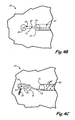
- FIGS. 1 and 2 illustrate an elongated pressure vessel 10, such as that disclosed in U.S. Patent No. 5,476,189 .
- Vessel 10 has a main body section 12 with end sections 14.
- a boss 16, typically constructed of aluminum, is provided at one or both ends of the vessel 10 to provide a port for communicating with the interior of the vessel 10.
- the vessel 10 is formed from an inner polymer liner 20 covered by an outer composite shell 18.
- composite means a fiber reinforced resin matrix material, such as a filament wound or laminated structure.
- the composite shell 18 resolves all structural loads and liner 20 provides a gas barrier.
- a pressure vessel When a pressure vessel is exposed to intense heat, as in the case of a fire, the heat increases the pressure of the gas in the vessel.
- one or more rupture discs are provided in a valve body at the end port of the vessel. These discs react to the pressure increase to release gas before the tank ruptures.
- the composite does not heat like steel and thus the pressure does not rise in the tank in the same manner (so that a pressure release valve actuated by an increase in pressure is not appropriate).
- the pressure in the composite vessel increases, ultimately causing a rupture, thereby resulting in an uncontrolled release of gas and/or an explosion.
- a plurality of temperature sensors are positioned at discrete locations along a tank. Such sensors are operably coupled to one or more pressure relief valves for the tank. Such coupling may be accomplished electrically, chemically, mechanically, or by a pressurized line. In an example, a plurality of discrete sensors are fastened into a pressurized tubing that runs along the outside of the tank.
- some authorities regulating the transportation of certain goods e.g., high pressure gas
- the use of sensors positioned at discrete locations on a tank leaves portions of the tank that are free from sensor coverage.
- US 2005/0011 563 discloses an apparatus according to the preamble of claim 1.
- This disclosure describes an apparatus according to claim 1 comprising a valve and an elongated shape memory alloy element.
- the valve comprises a lever in a first position, whereby the valve is closed.
- the elongated shape memory alloy element has a first end connected to the lever.
- the shape memory alloy element has been strained to have a first length, wherein exposure of at least a portion of the shape memory alloy element to a temperature at or exceeding its austenite transformation temperature causes the shape memory alloy element to shorten to a second length, the second length being less than the first length, thereby causing the first end of the shape memory alloy element to pull the lever to a second position, whereby the valve is opened.
- This disclosure provides a sensor and valve assembly for controlled depressurization of a pressure vessel, such as a composite cylindrical gas storage vessel, in particular when the vessel is exposed to a fire.
- the present disclosure provides a temperature activated sensor and valve assembly 21 for releasing gas from within the vessel, rather than relieving excess gas using a valve based upon pressure.
- a piece of tubing 22 is mounted on the outside of the pressure vessel 10' to run along the length of vessel 10'.
- tubing 22 is made of stainless steel and has an outside diameter of 6,35 mm (0.25 inch).
- tubing 22 has perforations 40 (shown in FIG. 4C ) to allow freer heat flow into tubing 22.
- Pressure relief or release valve (PRV) 24 is mounted on boss 16' near first end 26 of tubing 22 (see FIG. 4A ).
- SMA shape memory alloy
- wire 28 An elongated shape memory alloy (SMA) element, such as wire 28, is 'set' by straining (stretching of wire 28) approximately 10%. This straining is achieved at a temperature below the SMA's austenite start temperature.
- the strained wire 28 is threaded inside tubing 22, which is fixed relative to a lever 32 of PRV 24.
- a first end 30 of the wire 28 is attached to lever 32 of PRV 24.
- a second end 34 of wire 28 is fixed relative to tubing 22, such as by being attached to a second end 36 of tubing 22 (such as by a mechanical fastener or by swaging the second end 36 of the tubing 22 over the second end 34 of wire 28).
- second end 34 of wire 28 is positionally fixed relative to pressure vessel 10'.
- PRV 24 is a conventional quarter-turn valve.
- FIG. 4A shows PRV 24 in a closed position, wherein lever 32 is in a vertical position.
- rotating lever 32 about ninety degrees to the positions shown in FIGS. 4B or 4C ) opens the valve, thereby allowing gas to escape from boss 16'.
- heating of wire 28 to or beyond its austenite transformation temperature causes the wire 28 to shrink by 6-8 %.
- the strain recovered by wire 28 causes it to shorten by 18,29 mm to 24,38 mm (0.72 to 0.96 inch).
- first end 30 pulls with a force of approximately 54.43 kg (120 pounds) (for a wire diameter of 1.52 mm (0.06 inch)) and thereby turns lever 32 to open PRV 24.
- the disclosed trigger is designed so that exposure of a requisite portion of the vessel 10' to or in excess of the transformation temperature of wire 28 causes a shortening of wire 28 that is adequate to pull lever 32 to the open position illustrated in FIG. 4B .
- PRV 24 is designed to trigger with a total wire 28 shrinkage of 25.4 mm (1 inch) While end 30 of wire 28 is attached to an end of lever 32 in the illustrated embodiments, wire 28 can be attached to lever 32 at another location, as appropriate for a particular application, taking into account the displacement and pulling force required to open PRV 24.
- the heat for triggering sensor and valve assembly 21 can be present anywhere along the length of the SMA wire 28.
- SMA wire 28 is run in a substantially straight line parallel to the vessel surface along substantially the entire length of vessel 10', thereby protecting the pressure vessel 10' over its entire length.
- tubing 22 and wire 28 are run to additional locations where a fire or elevated temperature might be detected. If any portion of the wire 28 is heated past an established temperature, the wire will shrink by a certain degree. If enough of the wire 28 shrinks, movement of the end 30 of wire 28 pulls on lever 32 to open PRV 24. With PRV 24 thus opened, pressurized gas from within the vessel 10' can escape through the open PRV 24 in a controlled manner.
- SMA wire 28 acts as a temperature sensor along the entire length of the vessel 10' and can thus react to localized fires to allow release of gas from vessel 10'.
- the disclosed trigger arrangement can be used to protect a vessel of any length, even very long pressure vessels.
- More than one tubing 22 and wire 28 can be used on a single valve 24.
- the tubing 22 and wire 28 are not limited to straight runs, but can be bent, so long as the wire 28 is moveable within the tubing 22.
- SMA wire 28 laid in a spiral configuration from one end of the tank to the other offers protection on all sides of the tank as well as protection for the length of the tank.
- the tubing 22 protects the sensor wire 28 from environmental conditions that might adversely affect its performance. This arrangement results in a relatively inexpensive sensor assembly 21.
- the disclosed sensor assembly 21 minimizes false triggering, since the PRV 24 will only be buggered when the wire 28 is exposed to a temperature that exceeds the austenite transformation temperature.
- the transformation temperature is determined by the wire alloy composition.
- the alloy is 54.79 weight percent Nickel and 45.21 weight percent Titanium and has a transformation temperature of 100°C (212°F).
- the amount of force can be controlled by selecting the cross-section area (e.g., diameter) of the shape memory element or wire 28.
- An exemplary wire having a diameter of about 1,52 mm (0.06 inch) produces approximately 54,43 kg (120 pounds) of pull once the ambient temperature exceeds the transformation temperature of the particular alloy. More force is accomplished with a wire having a larger cross-sectional area.
- the force developed is essentially independent of length and temperature; thus, higher temperatures or more heat input will not significantly increase or decrease the force developed due to transformation.
- the pressure release device is also set to be triggered if the wire 28 is severed.
- lever 32 is biased (such as by spring 38) in the direction shown in FIG. 4C , which is offset from the "off" position of FIG. 4A by a rotational angle of about 90 degrees (in the direction opposite the offset between the "off” and “on” positions shown in FIGS. 4A and 4B , respectively).
- second end 34 is wire 28 is attached to the lever of a second PRV. This would allow two PRV's to activate, venting the vessel 10' from both ends 14'.
- the disclosed tubing and SMA valve and sensor assembly 21 can be used to actuate any device (not just a PRV) such as, for example, a fire suppression system.
Landscapes
- Engineering & Computer Science (AREA)
- General Engineering & Computer Science (AREA)
- Mechanical Engineering (AREA)
- Health & Medical Sciences (AREA)
- Oral & Maxillofacial Surgery (AREA)
- Filling Or Discharging Of Gas Storage Vessels (AREA)
- Safety Valves (AREA)
- Temperature-Responsive Valves (AREA)
Applications Claiming Priority (2)
| Application Number | Priority Date | Filing Date | Title |
|---|---|---|---|
| US15690009P | 2009-03-03 | 2009-03-03 | |
| PCT/US2010/026009 WO2010101976A1 (en) | 2009-03-03 | 2010-03-03 | Shape memory alloy trigger for pressure relief valve |
Publications (2)
| Publication Number | Publication Date |
|---|---|
| EP2404090A1 EP2404090A1 (en) | 2012-01-11 |
| EP2404090B1 true EP2404090B1 (en) | 2015-07-15 |
Family
ID=42174642
Family Applications (1)
| Application Number | Title | Priority Date | Filing Date |
|---|---|---|---|
| EP10707757.0A Active EP2404090B1 (en) | 2009-03-03 | 2010-03-03 | Shape memory alloy trigger for pressure relief valve |
Country Status (11)
| Country | Link |
|---|---|
| US (1) | US8820069B2 (https=) |
| EP (1) | EP2404090B1 (https=) |
| JP (1) | JP5738776B2 (https=) |
| KR (1) | KR101501048B1 (https=) |
| CN (1) | CN102341630B (https=) |
| AU (1) | AU2010221443B2 (https=) |
| BR (1) | BRPI1007868B1 (https=) |
| CA (1) | CA2753386C (https=) |
| ES (1) | ES2547280T3 (https=) |
| RU (1) | RU2500943C2 (https=) |
| WO (1) | WO2010101976A1 (https=) |
Families Citing this family (27)
| Publication number | Priority date | Publication date | Assignee | Title |
|---|---|---|---|---|
| US8720722B2 (en) * | 2005-12-15 | 2014-05-13 | Cornerstone Research Group, Inc. | Venting mechanism for containers |
| US10226991B2 (en) * | 2009-10-28 | 2019-03-12 | GM Global Technology Operations LLC | Air curtain using smart materials |
| DE102011001140A1 (de) * | 2011-03-08 | 2012-09-13 | Thyssenkrupp Steel Europe Ag | Stahlflachprodukt, Verfahren zum Herstellen eines Stahlflachprodukts und Verfahren zum Herstellen eines Bauteils |
| WO2013047820A1 (ja) * | 2011-09-30 | 2013-04-04 | 新日鐵住金株式会社 | 溶融亜鉛めっき鋼板及びその製造方法 |
| KR20150135248A (ko) | 2013-03-06 | 2015-12-02 | 콩스베르그 오토모티브 아베 | 형상 기억 합금 부재를 구비한 유체 라우팅 장치 |
| US9097358B2 (en) | 2013-05-01 | 2015-08-04 | Emcara Gas Development Inc. | Valve with temperature activated trigger having novel material configuration |
| CN105813887B (zh) | 2013-12-13 | 2017-11-10 | 康斯博格汽车股份公司 | 用于控制到车辆座椅内空气单元的加压空气供给的sma阀 |
| CN105829164B (zh) | 2013-12-13 | 2019-01-18 | 康斯博格汽车股份公司 | 用于控制到车辆座椅内空气单元的加压空气供给的sma阀 |
| WO2015086094A1 (en) | 2013-12-13 | 2015-06-18 | Kongsberg Automotive Ab | Sma valve for controlling air supply to an air cell in a vehicle seat |
| DE102014000616B4 (de) | 2014-01-18 | 2025-01-02 | Cellcentric Gmbh & Co. Kg | Thermisch auslösendes Sicherheitsventil |
| WO2015185132A1 (en) | 2014-06-04 | 2015-12-10 | Kongsberg Automotive Ab | Sma valve for controlling pressurized air supply to an air cell in a vehicle seat |
| CN104197188B (zh) * | 2014-08-25 | 2017-02-01 | 上海宇航系统工程研究所 | 一种形状记忆合金丝驱动喷气装置 |
| GB2531265A (en) * | 2014-10-13 | 2016-04-20 | Graviner Ltd Kidde | A frangible plug for use in a valve mechanism |
| US9416878B1 (en) | 2015-02-16 | 2016-08-16 | Kongsberg Automotive, Inc. | Valve including a shape memory alloy member |
| NO20150851A1 (en) * | 2015-07-01 | 2016-09-12 | Techinvent As | An apparatus for controlling a fluid flow |
| CN108730604B (zh) * | 2017-04-14 | 2024-06-07 | 国家电力投资集团公司 | 非能动阀门系统 |
| CN107327692A (zh) * | 2017-07-17 | 2017-11-07 | 凯迈(洛阳)气源有限公司 | 一种飞行器用气瓶 |
| PL3672823T3 (pl) | 2017-09-14 | 2024-01-03 | Agility Fuel Systems Llc | Systemy do monitorowania komponentów układu paliwa lotnego |
| US10942533B2 (en) * | 2018-02-14 | 2021-03-09 | Hexagon Technology As | System for multiple pressure relief device activation |
| EP3903017B1 (en) * | 2019-03-12 | 2023-03-22 | Nikola Corporation | Pressurized vessel heat shield and thermal pressure relief system |
| KR102187342B1 (ko) | 2019-09-03 | 2020-12-04 | (주)삼익브리즈 | 공조기의 열교환기용 동파방지 릴리프밸브 |
| WO2021108387A1 (en) * | 2019-11-25 | 2021-06-03 | Agility Fuel Systems Llc | Improved pressure relief device |
| CN111623157A (zh) * | 2020-06-24 | 2020-09-04 | 西安空天引擎科技有限公司 | 一种形状记忆合金隔离阀 |
| CN113124247B (zh) * | 2021-04-30 | 2022-05-20 | 中国工程物理研究院机械制造工艺研究所 | 一种可实现高温泄气安全保护的管路密封结构、管路密封和高温泄气方法 |
| CN113431915B (zh) * | 2021-07-02 | 2023-01-24 | 威海观复燃气安全科技有限公司 | 一种液化石油气自闭阀 |
| CN114877111B (zh) * | 2022-07-12 | 2022-12-09 | 山东拙诚智能科技有限公司 | 一种燃气安全控制装置 |
| FR3163997A1 (fr) * | 2024-07-01 | 2026-01-02 | L'air Liquide, Societe Anonyme Pour L'etude Et L'exploitation Des Procedes Georges Claude | Injecteur pour un réservoir de gaz et réservoir équipé d’un tel injecteur. |
Family Cites Families (49)
| Publication number | Priority date | Publication date | Assignee | Title |
|---|---|---|---|---|
| FR1115990A (fr) * | 1953-11-16 | 1956-05-02 | Gen Motors Corp | Réfrigérateur perfectionné |
| US3489309A (en) | 1966-12-13 | 1970-01-13 | Foster Wheeler Corp | Pressure vessels |
| US3613732A (en) | 1969-07-17 | 1971-10-19 | Robertshaw Controls Co | Temperature-responsive valve operators |
| US3914991A (en) | 1973-07-24 | 1975-10-28 | Nasa | Strain gage mounting assembly |
| DE2728651C2 (de) | 1977-06-24 | 1981-09-17 | Siempelkamp Gießerei GmbH & Co, 4150 Krefeld | Verfahren zur Überwachung eines zylindrischen Kernreaktordruckbehälters sowie Vorrichtungen zur Durchführung eines derartigen Verfahrens |
| US4284235A (en) * | 1979-12-19 | 1981-08-18 | Werner Diermayer | Vent control arrangement for combustion apparatus |
| JPS5874666U (ja) * | 1981-11-13 | 1983-05-20 | 東北金属工業株式会社 | 感温バルブ |
| JPS58132273A (ja) * | 1982-02-02 | 1983-08-06 | 日本電信電話株式会社 | フレキシブル分散形elマトリツクス表示素子 |
| JPS58132273U (ja) * | 1982-03-03 | 1983-09-06 | 奥原 克美 | ガス漏れ防止装置 |
| US4570851A (en) | 1984-05-07 | 1986-02-18 | Cirillo John R | Temperature regulating, pressure relief flow valves employing shaped memory alloys |
| JPS61121341A (ja) | 1984-11-16 | 1986-06-09 | Mitsubishi Electric Corp | ガラスパツシベ−シヨン形半導体装置の製造方法 |
| JPS61121341U (https=) * | 1985-01-16 | 1986-07-31 | ||
| US4840346A (en) * | 1985-04-11 | 1989-06-20 | Memory Metals, Inc. | Apparatus for sealing a well blowout |
| US4884780A (en) | 1985-04-26 | 1989-12-05 | Nissan Motor Company, Limited | Valve actuating arrangement |
| JPS61183417U (https=) | 1985-05-07 | 1986-11-15 | ||
| JPS62129487A (ja) | 1985-11-30 | 1987-06-11 | 大同特殊鋼株式会社 | 開閉板の開閉駆動装置 |
| US4699314A (en) * | 1986-12-17 | 1987-10-13 | Carrier Corporation | Actuator for a heating/cooling diffuser |
| JPS63162265A (ja) | 1986-12-26 | 1988-07-05 | Canon Inc | プリンタ |
| JPS63162265U (https=) * | 1987-04-08 | 1988-10-24 | ||
| US4965545A (en) * | 1989-08-09 | 1990-10-23 | Tini Alloy Company | Shape memory alloy rotary actuator |
| US4973024A (en) * | 1989-09-26 | 1990-11-27 | Toki Corporation Kabushiki Kaisha | Valve driven by shape memory alloy |
| US5277028A (en) | 1990-03-26 | 1994-01-11 | Mercedes-Benz Ag | Hydraulic flow control with temperature sensitive spring biased bypass valve |
| US5211371A (en) * | 1991-07-22 | 1993-05-18 | Advanced Control Technologies, Inc. | Linearly actuated valve |
| US5165450A (en) * | 1991-12-23 | 1992-11-24 | Texaco Inc. | Means for separating a fluid stream into two separate streams |
| GB2272276B (en) * | 1992-11-06 | 1995-03-29 | Kim San Toh | Improvements in LPG cylinders |
| US5476189A (en) | 1993-12-03 | 1995-12-19 | Duvall; Paul F. | Pressure vessel with damage mitigating system |
| US5522428A (en) | 1994-08-29 | 1996-06-04 | Duvall; Paul F. | Natural gas vehicle tank life sensor and control |
| US5518140A (en) | 1994-11-07 | 1996-05-21 | Cryenco, Inc. | Liquified gas storage tank overfill protection system and method |
| US5462226A (en) * | 1994-11-07 | 1995-10-31 | Itt Corporation | Temperature-responsive, locking mechanism for, and in combination with, a fluid valve |
| US5586722A (en) | 1995-05-05 | 1996-12-24 | Murray; Jerome L. | Temperature and flow control valve |
| US5662139A (en) * | 1995-09-08 | 1997-09-02 | Lish; Dennis N. | Pressure relief valve with lockout position |
| US5788212A (en) | 1996-07-26 | 1998-08-04 | Gas Research Institute | Pressure relief device with shaped memory alloy thermally activated trigger |
| TW386150B (en) * | 1996-11-08 | 2000-04-01 | Matsushita Electric Works Ltd | Flow control valve |
| US6269830B1 (en) | 1998-09-28 | 2001-08-07 | Gas Research Institute | Extended area thermal activation device |
| JP3065038U (ja) | 1999-04-22 | 2000-01-28 | 國弘 主税 | 形状記憶合金の収縮力を利用した、消火器用ボンベの自動開封装置 |
| FR2796701B1 (fr) * | 1999-07-22 | 2001-09-07 | Giat Ind Sa | Soupape de surete pour enceinte etanche contenant un fluide sous pression telle un reservoir gpl |
| RU2188683C1 (ru) * | 2000-12-28 | 2002-09-10 | Сильянов Виталий Анатольевич | Огнетушитель |
| EP1364125A1 (en) * | 2001-01-17 | 2003-11-26 | M 2 Medical A/S | Shape memory alloy actuator |
| WO2002090807A1 (en) | 2001-05-08 | 2002-11-14 | Scuola Superiore Di Studi Universitari E Di Perfezionamento S. Anna | Proportional valve with shape memory alloy (sma) actuator |
| ITTO20010618A1 (it) * | 2001-06-27 | 2002-12-27 | Fiat Ricerche | Dispositivo attuatore a cavo flessibile incorporante un elemento a memoria di forma. |
| DK1546554T3 (da) | 2002-07-24 | 2009-02-23 | M2 Medical As | Aktuator af en legering med formhukommelse |
| US6955187B1 (en) * | 2003-07-16 | 2005-10-18 | Tini Alloy Company | Zinc-air battery control valve |
| ITTO20030553A1 (it) * | 2003-07-17 | 2005-01-18 | Fiat Ricerche | Dispositivo di controllo del flusso di un fluido |
| WO2005026592A2 (en) * | 2003-09-05 | 2005-03-24 | Alfmeier Präzision AG Baugruppen und Systemlösungen | A system, method and apparatus for reducing frictional forces and for compensating shape memory alloy-actuated valves and valve systems at high temperatures |
| US20080148853A1 (en) | 2003-09-22 | 2008-06-26 | Hyeung-Yun Kim | Gas tank having usage monitoring system |
| DE102004062241A1 (de) * | 2004-12-23 | 2006-07-13 | BSH Bosch und Siemens Hausgeräte GmbH | Betätigungsvorrichtung für Ventile |
| US7815161B2 (en) * | 2005-07-26 | 2010-10-19 | Panasonic Electric Works Co., Ltd. | Compact valve |
| US20080319688A1 (en) | 2007-02-26 | 2008-12-25 | Hyeung-Yun Kim | Usage monitoring system of gas tank |
| US8499779B2 (en) * | 2008-01-16 | 2013-08-06 | The United States Of America As Represented By The Administrator Of The National Aeronautics Space Administration | Systems, methods and apparatus of a nitinol valve |
-
2010
- 2010-03-03 US US13/254,346 patent/US8820069B2/en active Active
- 2010-03-03 CA CA2753386A patent/CA2753386C/en active Active
- 2010-03-03 BR BRPI1007868-1A patent/BRPI1007868B1/pt not_active IP Right Cessation
- 2010-03-03 EP EP10707757.0A patent/EP2404090B1/en active Active
- 2010-03-03 AU AU2010221443A patent/AU2010221443B2/en not_active Ceased
- 2010-03-03 RU RU2011139966/06A patent/RU2500943C2/ru active
- 2010-03-03 KR KR1020117022777A patent/KR101501048B1/ko not_active Expired - Fee Related
- 2010-03-03 CN CN2010800102698A patent/CN102341630B/zh not_active Expired - Fee Related
- 2010-03-03 JP JP2011553064A patent/JP5738776B2/ja not_active Expired - Fee Related
- 2010-03-03 ES ES10707757.0T patent/ES2547280T3/es active Active
- 2010-03-03 WO PCT/US2010/026009 patent/WO2010101976A1/en not_active Ceased
Also Published As
| Publication number | Publication date |
|---|---|
| US20120011843A1 (en) | 2012-01-19 |
| ES2547280T3 (es) | 2015-10-02 |
| JP2012519816A (ja) | 2012-08-30 |
| KR101501048B1 (ko) | 2015-03-10 |
| AU2010221443B2 (en) | 2014-11-27 |
| CN102341630B (zh) | 2013-09-18 |
| CA2753386C (en) | 2015-08-11 |
| EP2404090A1 (en) | 2012-01-11 |
| BRPI1007868A2 (pt) | 2018-02-14 |
| JP5738776B2 (ja) | 2015-06-24 |
| CA2753386A1 (en) | 2010-09-10 |
| RU2011139966A (ru) | 2013-04-10 |
| RU2500943C2 (ru) | 2013-12-10 |
| WO2010101976A1 (en) | 2010-09-10 |
| BRPI1007868B1 (pt) | 2020-09-15 |
| AU2010221443A1 (en) | 2011-09-08 |
| KR20110128321A (ko) | 2011-11-29 |
| CN102341630A (zh) | 2012-02-01 |
| US8820069B2 (en) | 2014-09-02 |
Similar Documents
| Publication | Publication Date | Title |
|---|---|---|
| EP2404090B1 (en) | Shape memory alloy trigger for pressure relief valve | |
| US9205373B2 (en) | Breather layer for exhausting permeate from pressure vessels | |
| EP0656506B1 (en) | Pressure vessel with damage mitigating system | |
| US5615702A (en) | Tank for storing pressurized hydrocarbons | |
| CN108930790B (zh) | 高压容器 | |
| AU2007246823B2 (en) | Improvements relating to hose | |
| EP3380779B1 (en) | Composite vessel fire protection system | |
| AU633945B2 (en) | Protective device for gas pressure vessels | |
| US11098851B2 (en) | High-pressure tank and attachment structure thereof | |
| US20200109791A1 (en) | Pressure-Relief Device With a Variable Mass Flow Rate | |
| JP7639772B2 (ja) | 流体タンク | |
| JPS61500371A (ja) | 可撓性管状導管 | |
| EP2473770B1 (en) | Fibre wound vessel | |
| US12241590B2 (en) | End fitting for a pressurized fluid reservoir |
Legal Events
| Date | Code | Title | Description |
|---|---|---|---|
| PUAI | Public reference made under article 153(3) epc to a published international application that has entered the european phase |
Free format text: ORIGINAL CODE: 0009012 |
|
| 17P | Request for examination filed |
Effective date: 20110922 |
|
| AK | Designated contracting states |
Kind code of ref document: A1 Designated state(s): AT BE BG CH CY CZ DE DK EE ES FI FR GB GR HR HU IE IS IT LI LT LU LV MC MK MT NL NO PL PT RO SE SI SK SM TR |
|
| DAX | Request for extension of the european patent (deleted) | ||
| 17Q | First examination report despatched |
Effective date: 20130301 |
|
| GRAP | Despatch of communication of intention to grant a patent |
Free format text: ORIGINAL CODE: EPIDOSNIGR1 |
|
| INTG | Intention to grant announced |
Effective date: 20150217 |
|
| GRAS | Grant fee paid |
Free format text: ORIGINAL CODE: EPIDOSNIGR3 |
|
| GRAA | (expected) grant |
Free format text: ORIGINAL CODE: 0009210 |
|
| AK | Designated contracting states |
Kind code of ref document: B1 Designated state(s): AT BE BG CH CY CZ DE DK EE ES FI FR GB GR HR HU IE IS IT LI LT LU LV MC MK MT NL NO PL PT RO SE SI SK SM TR |
|
| REG | Reference to a national code |
Ref country code: CH Ref legal event code: EP Ref country code: GB Ref legal event code: FG4D |
|
| REG | Reference to a national code |
Ref country code: IE Ref legal event code: FG4D |
|
| REG | Reference to a national code |
Ref country code: AT Ref legal event code: REF Ref document number: 736972 Country of ref document: AT Kind code of ref document: T Effective date: 20150815 |
|
| REG | Reference to a national code |
Ref country code: DE Ref legal event code: R096 Ref document number: 602010025890 Country of ref document: DE |
|
| REG | Reference to a national code |
Ref country code: ES Ref legal event code: FG2A Ref document number: 2547280 Country of ref document: ES Kind code of ref document: T3 Effective date: 20151002 |
|
| REG | Reference to a national code |
Ref country code: CH Ref legal event code: NV Representative=s name: ICB INGENIEURS CONSEILS EN BREVETS SA, CH |
|
| REG | Reference to a national code |
Ref country code: SE Ref legal event code: TRGR |
|
| REG | Reference to a national code |
Ref country code: NO Ref legal event code: T2 Effective date: 20150715 |
|
| REG | Reference to a national code |
Ref country code: NL Ref legal event code: MP Effective date: 20150715 |
|
| REG | Reference to a national code |
Ref country code: LT Ref legal event code: MG4D |
|
| PG25 | Lapsed in a contracting state [announced via postgrant information from national office to epo] |
Ref country code: LT Free format text: LAPSE BECAUSE OF FAILURE TO SUBMIT A TRANSLATION OF THE DESCRIPTION OR TO PAY THE FEE WITHIN THE PRESCRIBED TIME-LIMIT Effective date: 20150715 Ref country code: LV Free format text: LAPSE BECAUSE OF FAILURE TO SUBMIT A TRANSLATION OF THE DESCRIPTION OR TO PAY THE FEE WITHIN THE PRESCRIBED TIME-LIMIT Effective date: 20150715 Ref country code: FI Free format text: LAPSE BECAUSE OF FAILURE TO SUBMIT A TRANSLATION OF THE DESCRIPTION OR TO PAY THE FEE WITHIN THE PRESCRIBED TIME-LIMIT Effective date: 20150715 Ref country code: GR Free format text: LAPSE BECAUSE OF FAILURE TO SUBMIT A TRANSLATION OF THE DESCRIPTION OR TO PAY THE FEE WITHIN THE PRESCRIBED TIME-LIMIT Effective date: 20151016 |
|
| PG25 | Lapsed in a contracting state [announced via postgrant information from national office to epo] |
Ref country code: PT Free format text: LAPSE BECAUSE OF FAILURE TO SUBMIT A TRANSLATION OF THE DESCRIPTION OR TO PAY THE FEE WITHIN THE PRESCRIBED TIME-LIMIT Effective date: 20151116 Ref country code: HR Free format text: LAPSE BECAUSE OF FAILURE TO SUBMIT A TRANSLATION OF THE DESCRIPTION OR TO PAY THE FEE WITHIN THE PRESCRIBED TIME-LIMIT Effective date: 20150715 Ref country code: PL Free format text: LAPSE BECAUSE OF FAILURE TO SUBMIT A TRANSLATION OF THE DESCRIPTION OR TO PAY THE FEE WITHIN THE PRESCRIBED TIME-LIMIT Effective date: 20150715 |
|
| REG | Reference to a national code |
Ref country code: FR Ref legal event code: PLFP Year of fee payment: 7 |
|
| REG | Reference to a national code |
Ref country code: DE Ref legal event code: R097 Ref document number: 602010025890 Country of ref document: DE |
|
| PG25 | Lapsed in a contracting state [announced via postgrant information from national office to epo] |
Ref country code: SK Free format text: LAPSE BECAUSE OF FAILURE TO SUBMIT A TRANSLATION OF THE DESCRIPTION OR TO PAY THE FEE WITHIN THE PRESCRIBED TIME-LIMIT Effective date: 20150715 Ref country code: DK Free format text: LAPSE BECAUSE OF FAILURE TO SUBMIT A TRANSLATION OF THE DESCRIPTION OR TO PAY THE FEE WITHIN THE PRESCRIBED TIME-LIMIT Effective date: 20150715 Ref country code: EE Free format text: LAPSE BECAUSE OF FAILURE TO SUBMIT A TRANSLATION OF THE DESCRIPTION OR TO PAY THE FEE WITHIN THE PRESCRIBED TIME-LIMIT Effective date: 20150715 Ref country code: CZ Free format text: LAPSE BECAUSE OF FAILURE TO SUBMIT A TRANSLATION OF THE DESCRIPTION OR TO PAY THE FEE WITHIN THE PRESCRIBED TIME-LIMIT Effective date: 20150715 |
|
| PLBE | No opposition filed within time limit |
Free format text: ORIGINAL CODE: 0009261 |
|
| STAA | Information on the status of an ep patent application or granted ep patent |
Free format text: STATUS: NO OPPOSITION FILED WITHIN TIME LIMIT |
|
| PG25 | Lapsed in a contracting state [announced via postgrant information from national office to epo] |
Ref country code: RO Free format text: LAPSE BECAUSE OF FAILURE TO SUBMIT A TRANSLATION OF THE DESCRIPTION OR TO PAY THE FEE WITHIN THE PRESCRIBED TIME-LIMIT Effective date: 20150715 |
|
| 26N | No opposition filed |
Effective date: 20160418 |
|
| PG25 | Lapsed in a contracting state [announced via postgrant information from national office to epo] |
Ref country code: IS Free format text: LAPSE BECAUSE OF FAILURE TO SUBMIT A TRANSLATION OF THE DESCRIPTION OR TO PAY THE FEE WITHIN THE PRESCRIBED TIME-LIMIT Effective date: 20150715 |
|
| PG25 | Lapsed in a contracting state [announced via postgrant information from national office to epo] |
Ref country code: BE Free format text: LAPSE BECAUSE OF NON-PAYMENT OF DUE FEES Effective date: 20160331 Ref country code: SI Free format text: LAPSE BECAUSE OF FAILURE TO SUBMIT A TRANSLATION OF THE DESCRIPTION OR TO PAY THE FEE WITHIN THE PRESCRIBED TIME-LIMIT Effective date: 20150715 |
|
| PG25 | Lapsed in a contracting state [announced via postgrant information from national office to epo] |
Ref country code: LU Free format text: LAPSE BECAUSE OF FAILURE TO SUBMIT A TRANSLATION OF THE DESCRIPTION OR TO PAY THE FEE WITHIN THE PRESCRIBED TIME-LIMIT Effective date: 20160303 Ref country code: MC Free format text: LAPSE BECAUSE OF FAILURE TO SUBMIT A TRANSLATION OF THE DESCRIPTION OR TO PAY THE FEE WITHIN THE PRESCRIBED TIME-LIMIT Effective date: 20150715 |
|
| REG | Reference to a national code |
Ref country code: IE Ref legal event code: MM4A |
|
| PG25 | Lapsed in a contracting state [announced via postgrant information from national office to epo] |
Ref country code: BE Free format text: LAPSE BECAUSE OF FAILURE TO SUBMIT A TRANSLATION OF THE DESCRIPTION OR TO PAY THE FEE WITHIN THE PRESCRIBED TIME-LIMIT Effective date: 20150715 |
|
| PG25 | Lapsed in a contracting state [announced via postgrant information from national office to epo] |
Ref country code: IE Free format text: LAPSE BECAUSE OF NON-PAYMENT OF DUE FEES Effective date: 20160303 |
|
| REG | Reference to a national code |
Ref country code: FR Ref legal event code: PLFP Year of fee payment: 8 |
|
| PG25 | Lapsed in a contracting state [announced via postgrant information from national office to epo] |
Ref country code: NL Free format text: LAPSE BECAUSE OF FAILURE TO SUBMIT A TRANSLATION OF THE DESCRIPTION OR TO PAY THE FEE WITHIN THE PRESCRIBED TIME-LIMIT Effective date: 20150715 |
|
| REG | Reference to a national code |
Ref country code: AT Ref legal event code: UEP Ref document number: 736972 Country of ref document: AT Kind code of ref document: T Effective date: 20150715 |
|
| PG25 | Lapsed in a contracting state [announced via postgrant information from national office to epo] |
Ref country code: MT Free format text: LAPSE BECAUSE OF FAILURE TO SUBMIT A TRANSLATION OF THE DESCRIPTION OR TO PAY THE FEE WITHIN THE PRESCRIBED TIME-LIMIT Effective date: 20150715 |
|
| REG | Reference to a national code |
Ref country code: FR Ref legal event code: PLFP Year of fee payment: 9 |
|
| PG25 | Lapsed in a contracting state [announced via postgrant information from national office to epo] |
Ref country code: HU Free format text: LAPSE BECAUSE OF FAILURE TO SUBMIT A TRANSLATION OF THE DESCRIPTION OR TO PAY THE FEE WITHIN THE PRESCRIBED TIME-LIMIT; INVALID AB INITIO Effective date: 20100303 Ref country code: CY Free format text: LAPSE BECAUSE OF FAILURE TO SUBMIT A TRANSLATION OF THE DESCRIPTION OR TO PAY THE FEE WITHIN THE PRESCRIBED TIME-LIMIT Effective date: 20150715 Ref country code: SM Free format text: LAPSE BECAUSE OF FAILURE TO SUBMIT A TRANSLATION OF THE DESCRIPTION OR TO PAY THE FEE WITHIN THE PRESCRIBED TIME-LIMIT Effective date: 20150715 |
|
| PG25 | Lapsed in a contracting state [announced via postgrant information from national office to epo] |
Ref country code: MT Free format text: LAPSE BECAUSE OF FAILURE TO SUBMIT A TRANSLATION OF THE DESCRIPTION OR TO PAY THE FEE WITHIN THE PRESCRIBED TIME-LIMIT Effective date: 20160331 Ref country code: MK Free format text: LAPSE BECAUSE OF FAILURE TO SUBMIT A TRANSLATION OF THE DESCRIPTION OR TO PAY THE FEE WITHIN THE PRESCRIBED TIME-LIMIT Effective date: 20150715 |
|
| PG25 | Lapsed in a contracting state [announced via postgrant information from national office to epo] |
Ref country code: BG Free format text: LAPSE BECAUSE OF FAILURE TO SUBMIT A TRANSLATION OF THE DESCRIPTION OR TO PAY THE FEE WITHIN THE PRESCRIBED TIME-LIMIT Effective date: 20150715 |
|
| PGFP | Annual fee paid to national office [announced via postgrant information from national office to epo] |
Ref country code: AT Payment date: 20200219 Year of fee payment: 11 Ref country code: SE Payment date: 20200327 Year of fee payment: 11 |
|
| PGFP | Annual fee paid to national office [announced via postgrant information from national office to epo] |
Ref country code: CH Payment date: 20200401 Year of fee payment: 11 |
|
| REG | Reference to a national code |
Ref country code: CH Ref legal event code: PL |
|
| REG | Reference to a national code |
Ref country code: AT Ref legal event code: MM01 Ref document number: 736972 Country of ref document: AT Kind code of ref document: T Effective date: 20210303 |
|
| PG25 | Lapsed in a contracting state [announced via postgrant information from national office to epo] |
Ref country code: LI Free format text: LAPSE BECAUSE OF NON-PAYMENT OF DUE FEES Effective date: 20210331 Ref country code: CH Free format text: LAPSE BECAUSE OF NON-PAYMENT OF DUE FEES Effective date: 20210331 Ref country code: AT Free format text: LAPSE BECAUSE OF NON-PAYMENT OF DUE FEES Effective date: 20210303 Ref country code: SE Free format text: LAPSE BECAUSE OF NON-PAYMENT OF DUE FEES Effective date: 20210304 |
|
| PGFP | Annual fee paid to national office [announced via postgrant information from national office to epo] |
Ref country code: TR Payment date: 20220224 Year of fee payment: 13 Ref country code: NO Payment date: 20220329 Year of fee payment: 13 |
|
| PGFP | Annual fee paid to national office [announced via postgrant information from national office to epo] |
Ref country code: ES Payment date: 20220401 Year of fee payment: 13 |
|
| P01 | Opt-out of the competence of the unified patent court (upc) registered |
Effective date: 20230518 |
|
| REG | Reference to a national code |
Ref country code: NO Ref legal event code: MMEP |
|
| PG25 | Lapsed in a contracting state [announced via postgrant information from national office to epo] |
Ref country code: NO Free format text: LAPSE BECAUSE OF NON-PAYMENT OF DUE FEES Effective date: 20230331 |
|
| PG25 | Lapsed in a contracting state [announced via postgrant information from national office to epo] |
Ref country code: ES Free format text: LAPSE BECAUSE OF NON-PAYMENT OF DUE FEES Effective date: 20230304 |
|
| REG | Reference to a national code |
Ref country code: ES Ref legal event code: FD2A Effective date: 20240426 |
|
| PG25 | Lapsed in a contracting state [announced via postgrant information from national office to epo] |
Ref country code: ES Free format text: LAPSE BECAUSE OF NON-PAYMENT OF DUE FEES Effective date: 20230304 |
|
| PGFP | Annual fee paid to national office [announced via postgrant information from national office to epo] |
Ref country code: GB Payment date: 20240327 Year of fee payment: 15 |
|
| PGFP | Annual fee paid to national office [announced via postgrant information from national office to epo] |
Ref country code: IT Payment date: 20240321 Year of fee payment: 15 Ref country code: FR Payment date: 20240325 Year of fee payment: 15 |
|
| GBPC | Gb: european patent ceased through non-payment of renewal fee |
Effective date: 20250303 |
|
| PG25 | Lapsed in a contracting state [announced via postgrant information from national office to epo] |
Ref country code: GB Free format text: LAPSE BECAUSE OF NON-PAYMENT OF DUE FEES Effective date: 20250303 |
|
| PG25 | Lapsed in a contracting state [announced via postgrant information from national office to epo] |
Ref country code: IT Free format text: LAPSE BECAUSE OF NON-PAYMENT OF DUE FEES Effective date: 20250303 Ref country code: FR Free format text: LAPSE BECAUSE OF NON-PAYMENT OF DUE FEES Effective date: 20250331 |
|
| PGFP | Annual fee paid to national office [announced via postgrant information from national office to epo] |
Ref country code: DE Payment date: 20260327 Year of fee payment: 17 |