EP2402809A1 - Vibrationsbeständiges Telezoomobjektiv mit fünf Linsengruppen - Google Patents
Vibrationsbeständiges Telezoomobjektiv mit fünf Linsengruppen Download PDFInfo
- Publication number
- EP2402809A1 EP2402809A1 EP11182760A EP11182760A EP2402809A1 EP 2402809 A1 EP2402809 A1 EP 2402809A1 EP 11182760 A EP11182760 A EP 11182760A EP 11182760 A EP11182760 A EP 11182760A EP 2402809 A1 EP2402809 A1 EP 2402809A1
- Authority
- EP
- European Patent Office
- Prior art keywords
- lens
- lens group
- zoom lens
- zoom
- group
- Prior art date
- Legal status (The legal status is an assumption and is not a legal conclusion. Google has not performed a legal analysis and makes no representation as to the accuracy of the status listed.)
- Granted
Links
Images


Classifications
-
- G—PHYSICS
- G02—OPTICS
- G02B—OPTICAL ELEMENTS, SYSTEMS OR APPARATUS
- G02B15/00—Optical objectives with means for varying the magnification
- G02B15/14—Optical objectives with means for varying the magnification by axial movement of one or more lenses or groups of lenses relative to the image plane for continuously varying the equivalent focal length of the objective
- G02B15/16—Optical objectives with means for varying the magnification by axial movement of one or more lenses or groups of lenses relative to the image plane for continuously varying the equivalent focal length of the objective with interdependent non-linearly related movements between one lens or lens group, and another lens or lens group
- G02B15/163—Optical objectives with means for varying the magnification by axial movement of one or more lenses or groups of lenses relative to the image plane for continuously varying the equivalent focal length of the objective with interdependent non-linearly related movements between one lens or lens group, and another lens or lens group having a first movable lens or lens group and a second movable lens or lens group, both in front of a fixed lens or lens group
- G02B15/167—Optical objectives with means for varying the magnification by axial movement of one or more lenses or groups of lenses relative to the image plane for continuously varying the equivalent focal length of the objective with interdependent non-linearly related movements between one lens or lens group, and another lens or lens group having a first movable lens or lens group and a second movable lens or lens group, both in front of a fixed lens or lens group having an additional fixed front lens or group of lenses
- G02B15/173—Optical objectives with means for varying the magnification by axial movement of one or more lenses or groups of lenses relative to the image plane for continuously varying the equivalent focal length of the objective with interdependent non-linearly related movements between one lens or lens group, and another lens or lens group having a first movable lens or lens group and a second movable lens or lens group, both in front of a fixed lens or lens group having an additional fixed front lens or group of lenses arranged +-+
-
- G—PHYSICS
- G02—OPTICS
- G02B—OPTICAL ELEMENTS, SYSTEMS OR APPARATUS
- G02B15/00—Optical objectives with means for varying the magnification
- G02B15/14—Optical objectives with means for varying the magnification by axial movement of one or more lenses or groups of lenses relative to the image plane for continuously varying the equivalent focal length of the objective
- G02B15/145—Optical objectives with means for varying the magnification by axial movement of one or more lenses or groups of lenses relative to the image plane for continuously varying the equivalent focal length of the objective having five groups only
- G02B15/1451—Optical objectives with means for varying the magnification by axial movement of one or more lenses or groups of lenses relative to the image plane for continuously varying the equivalent focal length of the objective having five groups only the first group being positive
- G02B15/145113—Optical objectives with means for varying the magnification by axial movement of one or more lenses or groups of lenses relative to the image plane for continuously varying the equivalent focal length of the objective having five groups only the first group being positive arranged +-++-
-
- G—PHYSICS
- G02—OPTICS
- G02B—OPTICAL ELEMENTS, SYSTEMS OR APPARATUS
- G02B27/00—Optical systems or apparatus not provided for by any of the groups G02B1/00 - G02B26/00, G02B30/00
- G02B27/64—Imaging systems using optical elements for stabilisation of the lateral and angular position of the image
- G02B27/646—Imaging systems using optical elements for stabilisation of the lateral and angular position of the image compensating for small deviations, e.g. due to vibration or shake
-
- G—PHYSICS
- G02—OPTICS
- G02B—OPTICAL ELEMENTS, SYSTEMS OR APPARATUS
- G02B5/00—Optical elements other than lenses
- G02B5/04—Prisms
Definitions
- the present invention relates to a zoom lens that is used for an optical apparatus, such as a digital still camera.
- Portability is now a very critical factor in such an optical apparatus as a digital still camera, and attempts to decrease the size and weight of a zoom lens, which is a camera lens, is progressing in order to decrease the size, thickness and weight of a camera main unit.
- a slight movement of a camera during photographing e.g. slight motion of a camera generated when the user presses a release button
- image blurring during exposure, which deteriorates the image quality.
- a zoom lens where a detection system for detecting a slight motion of a camera, a computing system for controlling a shift lens group according to the value that is output from the detection system, and a drive system for shifting the shift lens group, are combined, and the image blurring is corrected by driving the shift lens group so as to compensate the image blurring caused by the slight motion of the camera, has been disclosed (e.g. Japanese Patent Application Laid-Open No. 2005- 128186 ),
- a conventional optical system attempts to increase a faster shutter speed using a brighter zoom lens .
- using a bright zoom lens increases the size of the zoom lens since the aperture increases, in other words, an increase in the aperture and a decrease in the size and thickness of the camera are in a trade-off relationship.
- the present invention is a zoom lens which has a plurality of lens groups which are disposed in order from an object along an optical axis, wherein among the plurality of lens groups, a first lens group, which is disposed closest to the object, has a positive refractive power, and comprises an optical path refraction element for refracting an optical path, and a plurality of lens components which are disposed closer to the object than the optical path refraction element, and the plurality of lens components include at least one positive lens that satisfies a condition of ⁇ d > 50 , where vd is an Abbe number with respect to the d-line, and at least one of the lens groups, which are disposed closer to the image than the first lens group can move in a direction substantially perpendicular to the optical axis, as a shift lens group or a partial lens components constituting this lens group.
- ⁇ aw is a lateral magnification of the shift lens group in a wide-angle end state
- ⁇ bw is a lateral magnification of the zoom lens that is disposed between the shift lens group and the image in the wide-angle end state.
- the plurality of lens components are formed of two lenses.
- the plurality of lens components are formed of a negative lens and a positive lens which are disposed in order from the object.
- the plurality of lens components comprise a negative meniscus lens having a convex surface facing the object, and a positive meniscus lens having a convex surface facing the object, which are disposed in order from the object.
- the shift lens group is fixed during zooming from a wide-angle end state to a telephoto end state.
- the shift lens group comprises a plurality of lens components.
- the shift lens group comprises a cemented lens.
- fw is a focal length of the zoom lens in the wide-angle end state
- fs is a focal length of the shift lens group.
- the angle of view in the wide-angle end state is 75 degrees or more.
- an aperture stop is disposed near the shift lens group.
- an aperture stop is disposed near the object side of the lens component disposed closest to the object in the lens group that includes the shift lens group.
- vd1 is an Abbe number, with respect to the d-line, of a negative lens closest to the object among the plurality of lens components.
- vd2 is an Abbe number, with respect to the d-line, of a positive lens closest to the image among the plurality of lens components.
- nd1 is a refractive index, with respect to the d-line, of a negative lens closest to the object among the plurality of lens components.
- nd2 is a refractive index, with respect to the d-line, of a positive lens closest to the image among the plurality of lens components.
- the second lens group which is disposed to the image side of the first lens group among the plurality of lens groups, has a negative refractive index, and a condition of 0.4 ⁇ 1 - f ⁇ 2 / fw ⁇ 1.9 is satisfied, where fw is a focal length of the zoom lens in the wide-angle end state, and f2 is a focal length of the second lens group.
- f1 is a focal length of the first lens group
- f2 is a focal length of the second lens group which is disposed to the image side of the first lens group, among the plurality of lens groups.
- the plurality of lens groups comprise at least the first lens group, a second lens group, and a third lens group which are disposed in order from the object along an optical axis, and the third lens group is the shift lens group.
- the plurality of lens groups comprise the first lens group, a second lens group, a third lens group, a fourth lens group, and a fifth lens group, which are disposed in order from the object along an optical axis, and the third lens group is the shift lens group.
- the second lens group has a negative refractive power
- the third lens group has a positive refractive power
- the fourth lens group has a positive refractive power
- the fifth lens group has a negative refractive power
- the third lens group is the shift lens group.
- the present invention is also an optical apparatus which has a zoom lens that forms an image of an object on a predetermined image surface, wherein the zoom lens is the zoom lens according to one of Claim 1 to Claim 20.
- the present invention is also a method for forming an image of an object on a predetermined image that uses a zoom lens which has a plurality of lens groups which are disposed in order from the object along an optical axis, wherein a first lens group, which is disposed closest to the object among the plurality of lens groups, has a positive refractive power, an optical path refraction element for refracting an optical path and a plurality of lens components, which are disposed closer to the object than the optical path refraction element, are disposed, and the plurality of lens components include at least one positive lens that satisfies a condition of ⁇ d > 50 , where vd is an Abbe number with respect to the d-line, and at least one of the lens groups disposed closer to the image than the first lens group can shift to a direction substantially perpendicular to the optical axis as a shift lens group, or partial lens components constituting this lens group.
- the present invention can implement a zoom lens that can shift images and still obtain high image formation performance with compact size, and an optical apparatus and a method for forming an image of an object that uses this zoom lens.
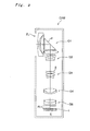
- Fig. 1 shows a digital still camera CAM which has a zoom lens ZL according to the present embodiment.
- Fig. 1A shows a front view of the digital still camera
- FIG 1B shows a rear view thereof.
- Fig. 2 is a cross-sectional view along II - II indicated by the arrow marks in Fig. 1A , and shows an overview of the later mentioned zoom lens ZL.
- a power button which is not illustrated, is pressed, a shutter, which is not illustrated, of a camera lens (ZL) is released, and lights from an object are condensed by the camera lens (ZL), and an image is formed by an image sensing element C, which is disposed on an image surface I.
- An object image formed on an image sensing element C is displayed on a liquid crystal monitor M disposed on the back of the digital still camera CAM. The user determines the composition of the object image using the liquid crystal monitor M, then presses the release button B1 to capture the object image by the image sensing element C, and to store the image in a memory, which is not illustrated.
- the camera lens is comprised of a zoom lens ZL according to the present embodiment, and since the optical path of the light, which entered from the front face of the digital still camera CAM, is refracted roughly 90 degrees downward (toward the bottom of the page in Fig. 2 ) by the optical path refraction element P in the zoom lens ZL, the digital still camera CAM can be slim.
- the digital still camera CAM further comprises an auxiliary light emission unit D that emits auxiliary light when the object is dark, a wide (W) tele (T) button B2 which is used when the zoom lens ZL is zoomed from the wide-angle end state (W) to the telephoto end state (T) , and a function button B3 which is used for setting various conditions of the digital still camera CAM.
- the zoom lens ZL of the present embodiment comprises a first lens group G1 which is disposed in order from an object and which has an optical path refraction element P and has a positive refractive power, a second lens group G2 which has a negative refractive power, a third lens group G3 which has a positive refractive power, a fourth lens group G4 which has a positive refractive power, and a fifth lens group G5 which has a negative refractive power, and an image on the image surface I can be shifted by shifting the entire third lens group G3 in a direction roughly perpendicular to the optical axis as a shift lens group.
- the first lens group G1, the third lens group G3 and the fifth lens group G5 are fixed with respect to the image surface I, and the second lens group G2 and the fourth lens group G4 move along the optical axis, whereby the distance between the first lens group G1 and the second lens group G2 increases, the distance between the second lens group G2 and the third lens group G3 decreases, the distance between the third lens group G3 and the fourth lens group G4 decreases, and the distance between the fourth lens group G4 and the fifth lens group G5 decreases (see Fig. 3 ) .
- a filter group FL comprised of a low pass filter and an infrared cut filter, for example, is disposed.
- the first lens group G1 is disposed closest to the object among the plurality of lens groups, which are disposed in order from the object, and is comprised of the optical path refraction element P for refracting the optical path, and a plurality of lens components which are disposed closer to an object than the optical path refraction element P, and has a function of refracting the optical path roughly 90 degrees and a function to converging the luminous flux. Constantly fixing the first lens group G1 during zooming from the wide-angle end state to the telephoto end state makes it unnecessary to move the lens group that is largest and heaviest among each lens group, and can simplify the structure of the zoom lens.
- the second lens group G2 functions to expand an image of an object, which is formed by the first lens group G1, and changes the focal length by widening the distance between the first lens group G1 and the second lens group G2 as the wide-angle end state shifts to the telephoto end state, so as to increase the expansion ratio.
- the third lens group G3 is comprised of a positive lens having a convex surface facing the object, and a cemented lens having a negative refractive power which has a positive lens having a convex surface facing the object and a negative lens having a concave surface facing the image, which are disposed in order from the object, and in the zoom lens ZL of the present embodiment, the image is shifted by shifting the entire lens group G3 in a direction roughly perpendicular to the optical axis as a shift lens group.
- the third lens group G3 not the entire lens group, but only a part of the lens components constituting the lens group may be shifted in a direction roughly perpendicular to the optical axis.
- the third lens group G3 having this configuration functions to converge the luminous flux expanded by the second lens group G2.
- the third lens group G3 is comprised of a plurality of lens groups where the spherical aberration, sine condition and Petzval sum are well corrected. Correcting the spherical aberration and sine condition can suppress the decentration coma aberration, which is generated at the center area of the screen when the shift lens group is shifted roughly perpendicular to the optical axis. Also correcting the Petzval sum can suppress the curvature of field, which is generated in the peripheral area of the screen when the shift lens group is shifted roughly perpendicular to the optical axis.
- the fourth lens group G4 has a function to further converge the luminous flux converged by the third lens group G3, and by actively changing the distance between the third lens group 3 and the fourth lens group G4 when zooming from the wide-angle end state to the telephoto end state, the fluctuation of the image surface with respect to the change of the focal length can be suppressed.
- the fifth lens group G5 has a negative refractive power, whereby the refractive power from the first lens group G1 to the fourth lens group G4 can be enhanced. As a result, the total length of the zoom lens can be decreased. In order to implement higher performance, it is preferable that the fifth lens group G5 is comprised of a plurality of lens groups.
- the zoom lens ZL comprises a plurality of lens components which are disposed closer to the object than the optical refraction element P, and the plurality of lens components include at least one positive lens that satisfies the following expression (1) where vd is an Abbe number with respect to the d-line. ⁇ d > 5
- the structure can be simplified and the coma aberration and lateral chromatic aberration, which are generated in the first lens group G1 alone, can be well corrected. If the condition of conditional expression (1) is not satisfied, the lateral chromatic aberration, which is generated in the first lens group G1, deteriorates.
- the numerator of conditional expression (2) is referred to as the "blur coefficient", which specifies an appropriate range for the moving amount of the image on the image surface I from the optical axis in the perpendicular direction with respect to the moving amount of the shift lens group in the wide-angle end state from the optical axis in a direction perpendicular to the optical axis.
- the right hand side (1 - ⁇ a) x ⁇ b of expression (B) is referred to as a blur coefficient.
- conditional expression (2) If the upper limit value of conditional expression (2) is exceeded, the moving amount of the image with respect to the moving amount of the shift lens group from the optical axis becomes too large, and the image moves considerably by a micro shift of the shift lens group, therefore the position control of the shift lens group becomes difficult, and sufficient accuracy cannot be implemented. Also the coma aberration and curvature of field deteriorate. If the lower limit value of conditional expression (2) is not reached, the moving amount of the image with respect to the moving amount of the shift lens group from the optical axis becomes relatively small, and the moving amount of the shift lens group that is required for cancelling the image blur, due to the motion blur, becomes extremely large. As a result, the size of the driving mechanism to move the shift lens group is increased, which makes downsizing of the lens diameter impossible. And the coma aberration also deteriorates.
- conditional expression (2) In order to insure the effect of the present embodiment, it is preferable to set the upper limit value of conditional expression (2) to 1.35. To further insure the effect of the present embodiment, it is more preferable to set the upper limit value of conditional expression (2) to 1.30. And in order to insure the effect the present embodiment, it is preferable to set the lower limit value of conditional expression (2) to 0.75. To further insure the effect of the present embodiment, it is more preferable to set the lower limit value of conditional expression (2) to 0.80.
- the plurality of lens components in the first lens group G1 are composed of two lenses, in order to implement a wider angle of view and higher performance.
- the structure can be simplified, and spherical aberration, which is generated in the first lens group G1 alone, can be well corrected with a minimum number of constituting lenses.
- the plurality of lens components in the first lens group G1 are composed of a negative lens and a positive lens which are disposed in order from the object, in order to implement both higher performance and smaller size.
- the structure can be simplified, and the spherical aberration and coma aberration, which are generated in the first lens group G1 alone, can be well corrected with the minimum number of constituting lenses.
- the first lens group G1 can be thin, and the size of the zoom lens can be decreased.
- the plurality of lens components in the first lens group G1 are composed of a negative meniscus lens and a positive meniscus lens which are disposed in order from the object, in order to implement both an even higher performance and smaller size.
- the shift lens group is fixed at zooming from the wide-angle end state to the telephoto end state. According to this configuration, complicating the drive mechanism to move the shift lens group can be prevented.
- the shift lens group (the third lens group G3 in the case of the present embodiment) comprises a plurality of lens components. According to this configuration, the spherical aberration, which is generated in the shift lens group alone, can be well corrected, and the position of an exit pupil can be distant from the image surface I as much as possible.
- the shift lens group comprises a cemented lens, in order to well correct the spherical aberration and axial chromatic aberration, which are generated in the shift lens group alone.
- a positive lens is added to the shift lens group. By this, the spherical aberration can be corrected even better.
- the conditional expression (3) specifies an appropriate focal length of the shift lens group. If the upper limit value of the conditional expression (3) is exceeded, the refractive power of the shift lens group becomes strong, and the spherical aberration, which is generated in the shift lens group alone, increases. If the lower limit value of the conditional expression (3) is not reached, the refractive power of the shift lens group becomes weak, and the shift lens group is no longer afocal, and as a result, the change of curvature of field increases when the lens is shifted.
- the angle of view in the wide-angle end state is 75 degrees or more, or even more preferably 80 degrees or more.
- the angle of view can be wide and flexibility in capturing images can be improved.
- an aperture stop is disposed near the shift lens group, or near the object side of a lens component, which is closest to the object of the lens group including the shift lens group, in order to balance the further improvement of performance and deterioration of performance during left shift.
- a lens group which can shift the image can maintain image forming performance well by performing lens shift using a lens group which is close to a stop where an off axis luminous flux passes near the optical axis during zooming, in order to minimize deterioration of performance during lens shift. Therefore the third lens group G3 is used as the shift lens group in the zoom lens ZL of the present embodiment, but the present invention is not limited to this.
- zoom lens ZL of the present embodiment it is preferable that the following Expression (4) is satisfied, where vd1 is an Abbe number, with respect to the d-line, of a negative lens closest to the object among the plurality of lens components. ⁇ d ⁇ 1 ⁇ 50
- the conditional expression (4) is a conditional expression to specify an optical material characteristic of a negative lens which is disposed closest to the object among a plurality of lens components which are disposed closer to the object than the optical path refraction element P in the first lens group G1, so as to implement a good lateral chromatic aberration. If the condition of the conditional expression (4) is not satisfied, the lateral chromatic aberration, that is generated in the first lens group G1, deteriorates.
- the conditional expression (5) is a conditional expression to specify an optical material characteristic of a positive lens which is disposed closest to the image among a plurality of lens components which are disposed closer to the object than the optical path refraction element P of the first lens group G1, so as to implement a good lateral chromatic aberration. If the condition of conditional expression (5) is not satisfied, the lateral chromatic aberration, that is generated in the first lens group G1, deteriorates. In order to insure the effect of the present embodiment, it is preferable to set the lower limit value of conditional expression (5) to 55.0. To further insure the effect of the present embodiment, it is more preferable to set the lower limit value of conditional expression (5) to 60.0.
- nd1 is a refractive index, with respect to the d-line, of a negative lens closest to the object among the plurality of lens components.
- nd ⁇ 1 1.75
- conditional expression (6) specifies an optical material characteristic of a negative lens which is disposed closer to the object than the optical path refraction element P of the first lens group G1, and is closest to the object.
- conditional of the conditional expression (6) If the conditional of the conditional expression (6) is not satisfied, the sizes of the effective diameter and outer diameter of the negative lens in the first lens group G1 increase, and the main body of the camera becomes large. Also correction of the coma aberration becomes difficult, and high optical performance can no longer be implemented.
- the conditional expression (7) specifies an optical material characteristic of a positive lens which is disposed closer to the object than the optical path refraction element P in the first lens group G1, and is closest to the image. If the condition of conditional expression (7) is not satisfied, the coma aberration and lateral chromatic aberration, which are generated in the first group G1, deteriorate.
- the conditional expression (8) specifies a range of an appropriate focal length of the second lens group G2. If the upper limit value of conditional expression (8) is exceeded, the refractive power of the second lens group G2 increases, and coma aberration and astigmatism, which are generated in the second lens group G2 alone, become too large, and the change of performance during photographing at a close distance increases. As a result, it becomes difficult to decrease the minimum photographing distance. If the lower limit value of the conditional expression (8) is not reached, the refractive power of the second lens group G2 becomes weak, and the moving amount to adjust the focal point increases, and the sizes of the elements of the drive system, which are required to move the lens, become large, which may interfere with other elements. If downsizing is attempted, spherical aberration deteriorates. As a result, saving space becomes difficult when the lens is installed in the main body of the camera.
- the upper limit value of conditional expression (8) it is preferable to set the upper limit value of conditional expression (8) to 1.75. To further insure the effect of the present embodiment, it is more preferable to set the upper limit value of conditional expression (8) to 1.55. To even further insure the effect of the present embodiment, it is more preferable to set the upper limit value of conditional expression (8) to 1.45. In order to insure the effect of the present embodiment, it is preferable to set the lower limit value of conditional expression (8) to 0.60. To further insure the effect of the present embodiment, it is more preferable to set the lower limit value of conditional expression (8) to 0.70. To even further insure the effect of the present embodiment, it is more preferable to set the lower limit value of conditional expression (8) to 0.80.
- the conditional expression (9) specifies an appropriate range of the focal length ratio between the first lens group G1 and the second lens group G2. If the upper limit value of conditional expression (9) is exceeded, the refractive power of the first lens group G1 becomes relatively weak, and the outer diameter of the entire first lens group G1 increases, which makes downsizing difficult. Also the refractive power of the second lens group G2 becomes relatively strong, and generation of coma aberration cannot be suppressed, and high optical performance cannot be implemented. If the lower limit value of conditional expression (9) is not reached, the refractive power of the first lens group G1 becomes relatively strong, which is advantageous for downsizing, but the spherical aberration and fluctuation of the curvature of field increase during zooming. Also the refractive power of the second lens group G2 becomes relatively weak, so this second lens group G2 cannot efficiently contribute to a variable power, and the moving amount required for variable power cannot be secured.
- conditional expression (9) it is preferable to set the upper limit value of conditional expression (9) to 3.55. To further insure the effect of the present embodiment, it is more preferable to set the upper limit value of conditional expression (9) to 3.4. In order to insure the effect of the present embodiment, it is preferable to set the lower limit value of conditional expression (9) to 2.5. To further insure the effect of the present embodiment, it is more preferable to set the lower limit value of conditional expression (9) to 2.6. To even further insure the effect of the present embodiment, it is more preferable to set the lower limit value of conditional expression (9) to 2.7.
- the optical path refraction element P is a prism
- L1 is a distance from the surface closest to the object of the first lens group G1 to the prism P
- Lp is a distance of the prism P on the optical axis.
- the total length of the zoom lens can be short even if the plurality of lens components are disposed to the object of the optical path refraction element P, and it becomes possible to decrease size and thickness of the zoom lens ZL according to the present embodiment (zoom lens ZL).
- conditional expression (10) specifies an appropriate range of the distance from the surface closest to the object of the first lens group G1 to the surface closest to the object of the optical path refraction element P on the optical path, and the distance of the optical path refraction element P on the optical path, and if the upper limit value of conditional expression (10) is exceeded, the total length of the lenses, which are disposed to the object of the optical path refraction element P, becomes long, and the thickness of the optical system increases. As a result, the thickness of the camera CAM increases, which makes it impossible to decrease size and thickness.
- conditional expression (10) it is preferable to set the upper limit value of conditional expression (10) to 0.95. To further insure the effect of the present embodiment, it is more preferable to set the upper limit value of conditional expression (10) to 0.9. To even further insure the effect of the present embodiment, it is more preferable to set the lower limit value of conditional expression (10) to 0.85.
- a blur detection system for detecting a blur of the zoom lens and drive means may be combined with the zoom lens, and all or a part of one lens group, among the lens groups constituting the zoom lens , is decentered with respect to the optical axis, as the shift lens group.
- the zoom lens ZL of the present embodiment is comprised of five lens groups, but another lens group may be added between each lens group, or another lens group may be added adjacent to the image or the object of the lens group.
- a zoom lens ZL comprises a first lens group G1 having a positive refractive power, a second lens group G2 having a negative refractive power, a third lens group G3 having a positive refractive power, a fourth lens group G4 having a positive refractive power, and a fifth lens group G5 having a negative refractive power, which are disposed in order from an object.
- a filter group FL comprised of a low pass filter and infrared cut filter is disposed.
- the third lens group G3 can move the entire lens group as a shift lens group in a direction roughly perpendicular to the optical axis, so as to enable the image shift in the zoom lens ZL.
- the present invention is not limited to this, but the third lens group G3 may shift not the entire lens group, but only a part of the lens components constituting the lens group in a direction roughly perpendicular to the optical axis.
- Fig. 3 shows the second lens group G2 and the fourth lens group G4 move along the optical axis, and the first lens group G1, the third lens group G3 and the fifth lens group G5 are fixed with respect to the image surface I during zooming from a wide-angle end state to a telephone end state.
- the distance of the first lens group G1 and the second lens group G2 increases, the distance between the second lens group G2 and the third lens group G3 decreases, the distance between the third lens group G3 and the fourth lens group G4 decreases, and the distance between the fourth lens group G4 and the fifth lens group G5 increases.
- Fig. 3 shows the movement of each lens group in the zoom lens GL according to each example, when the refractive power is allocated and the focal length state changes (zooming) from the wide-angle end state (W) to the telephoto end state (T).
- Table 1 to Table 4 are shown below, which are tables of each data of Example 1 to Example 4.
- f is a focal length
- FNO is an F number
- 2 ⁇ is an angle of view
- Bf is a back focus.
- the surface number shows a sequence of the lens surfaces which are disposed in order from an object in a light traveling direction (hereafter called "surface number")
- a surface distance is a distance from each optical surface to the next optical surface (or image surface) on the optical axis
- the refractive index and the Abbe number show values with respect to the d-line (wavelength: 587.6 nm).
- mm is generally used as a unit for focal length f, radius of curvature, surface distance, and other lengths.
- the unit is not limited to “mm”, but another appropriate unit can be used since similar optical performance can be implemented even if the optical system is proportionally expanded or reduced.
- "0.0000" of the radius of curvature indicates a plane, and the entry of refractive index "1.00000" of air is omitted.
- an aspherical surface with "*" is given by the following Expression (c), where y is height in a direction perpendicular to the optical axis, S (y) is a distance (sag amount) along the optical axis from the tangential plane at the vertex of the aspherical surface to the position on the aspherical surface at height y, r is a radius of curvature (paraxial radius of curvature) of the reference spherical surface, K is a conical coefficient, and An is an aspherical coefficient of degree n. In each example, the secondary aspherical coefficient A2 is 0, and entry thereof is omitted. En indicates ⁇ 10 n .
- 1.234E-05 1.234 ⁇ 10 -5 .
- S y y 2 / r / 1 + 1 - K ⁇ y 2 / r 2 1 / 2 + A ⁇ 2 ⁇ y 2 + A ⁇ 4 ⁇ y 4 + A ⁇ 6 ⁇ y 6 + A ⁇ 8 ⁇ y 8 + A ⁇ 10 ⁇ y 10
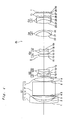
- FIG. 4 is a diagram depicting a configuration of a zoom lens ZL (in a wide-angle end state) according to Example 1 (the optical path refraction element P is shown in an expanded state) .
- a first lens group G1 is comprised of a negative meniscus lens L11 having a convex surface facing an object, a positive meniscus lens L12 having a convex surface facing the object, an optical path refraction element P, such as a rectangular prism, for refracting the optical path to about 90 degrees, and a biconvex positive lens L13 having an aspherical surface on both sides, which are disposed in order from the object.
- a second group G2 is comprised of a biconcave negative lens L21 having an aspherical surface to an image side, and a negative cemented lens L22 where a biconcave negative lens and a biconvex positive lens are bonded, which are disposed in order from the object.
- a third lens group G3 is comprised of a biconvex positive lens L31 having an aspherical surface to the object, and a negative cemented lens L32 where a positive meniscus lens having a convex surface facing the object and a negative meniscus lens having a concave surface facing the image are bonded, which are disposed in order from the object.
- a fourth lens group G4 is comprised of a positive cemented lens L41 where a biconvex positive lens having an aspherical surface to the object and a negative meniscus lens having a convex surface facing the image, are bonded.
- a fifth lens group G5 is comprised of a negative cemented lens L51, where a biconvex positive lens and a negative meniscus lens having a convex surface facing the object, are bonded.
- a filter group FL is disposed between the fifth lens group G5 and the image surface I.
- the image surface I is formed on the image sensing element, which is not illustrated, and this image sensing element is comprised of a CCD and CMOS (this is also the same for the examples described herein below).
- An aperture stop S is disposed in the third lens group G3, and is fixed with respect to the image surface I during zooming from the wide-angle end state to the telephoto end state.
- Table 1 shows the data of Example 1.
- the surface numbers 1 to 29 in Table 1 correspond to the surfaces 1 to 29 in Fig. 4 .
- each lens surface of the seventh, eighth, tenth, fifteenth and twentieth surface is formed in an aspherical shape.
- d8 is an axial air distance between the first lens group G1 and the second lens group G2
- d13 is an axial air distance between the second lens group G2 and the third lens group G3
- d19 is an axial air distance between the third lens group G3 and the fourth lens group G4
- d22 is an axial air distance between the fourth lens group G4 and the fifth lens group G5.
- the zoom lens ZL of the present example satisfies all conditional expressions (1) to (10).
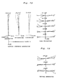
- Fig. 5 to Fig. 7 are graphs showing various aberrations of the zoom lens according to Example 1 with respect to the d-line (wavelength: 587.6 nm) and g-line (wavelength: 435.8 nm).
- FNO is an F number
- Y is an image height
- A is a half angle view with respect to each image height.
- the solid line indicates a sagittal image surface
- the broken line indicates a meridional image surface.
- the solid line indicates the spherical aberration
- the broken line indicates the sine condition.
- Example 1 As each aberration graph shows, in Example 1, various aberrations are well corrected in each focal length state from the wide-angle end state to the telephoto end state, and excellent image forming performance is implemented.
- FIG. 8 is a diagram depicting a configuration of a zoom lens ZL (in a wide-angle end state) according to Example 2.
- the zoom lens ZL of Example 2 has a similar configuration as Example 1, so each composing element is denoted with the same reference symbol as Example 1, for which detailed description is omitted.
- Table 2 shows each data of Example 2.
- the surface numbers 1 to 29 in Table 2 correspond to the surfaces 1 to 29 in Fig. 8 .
- each lens surface of the seventh, eighth, tenth, fifteenth and twentieth surface are formed in an aspherical shape .
- d8 is an axial air distance between the first lens group G1 and the second lens group G2
- d13 is an axial air distance between the second lens group G2 and the third lens group G3
- d19 is an axial air distance between the third lens group G3 and the fourth lens group G4
- d22 is an axial air distance between the fourth lens group G4 and the fifth lens group G5.
- the zoom lens ZL of the present example satisfies all the conditional expressions (1) to (10).
- Fig. 9 to Fig. 11 are graphs showing various aberrations of the zoom lens according to Example 2 with respect to the d-line (wavelength: 587.6 nm) and g-line (wavelength: 435.8 nm).
- Fig. 9A are graphs showing various aberrations of the zoom lens according to Example 2 with respect to the d-line (wavelength: 587.6 nm) and g-line (wavelength: 435.8 nm).
- Fig. 9A are graphs showing various aberrations of
- Example 2 As each aberration graph shows, in Example 2, various aberrations are well corrected in each focal length state from the wide-angle end state to the telephoto end state, and excellent image forming performance is implemented.
- FIG. 12 is a diagram depicting a configuration of a zoom lens ZL (in a wide-angle end state) according to Example 3.
- the zoom lens ZL of Example 3 has a similar configuration as Example 1, except for the configuration of the second lens group G2, so each composing element is denoted with the same reference symbol as Example 1, for which detailed description is omitted.
- a second lens group G2 of Example 3 is comprised of a biconcave negative lens L21 having an aspherical surface to the image, and a negative cemented lens L22 where a negative meniscus lens having a concave surface facing the image and a positive meniscus lens having a convex surface facing the object are bonded.
- an aperture stop S is disposed in the third lens group G3, and moves along the optical axis during zooming from the wide-angle end state to the telephoto end state.
- Table 3 shows each data of Example 3.
- the surface numbers 1 to 29 in Table 3 correspond to the surfaces 1 to 29 in Fig. 12 .
- each lens surface of the seventh, eighth, tenth, fifteenth and twentieth surface are formed in a spherical shape.
- d8 is an axial air distance between the first lens group G1 and the second lens group G2
- d13 is an axial air distance between the second lens group G2 and the aperture stop S
- d14 is an axial air distance between the aperture stop S and the third lens group G3
- d19 is an axial air distance between the third lens group G3 and the fourth lens group G4
- d22 is an axial air distance between the fourth lens group G4 and the fifth lens group G5.
- the zoom lens ZL of the present example satisfies all the conditional expressions (1) to (10).
- Fig. 13 to Fig. 15 are graphs showing various aberrations of the zoom lens according to Example 3 with respect to the d-line (wavelength: 587.6 nm) and g-line (wavelength: 435.8 nm).
- Example 3 As each aberration graph shows, in Example 3, various aberrations are well corrected in each focal length state from the wide-angle end state to the telephoto end state, and excellent image forming performance is implemented.
- FIG. 16 is a diagram depicting a configuration of a zoom lens ZL (in a wide-angle end state) according to Example 4.
- the zoom lens ZL of Example 4 has a similar configuration as Example 1, so each composing element is denoted with the same reference symbol as Example 1, for which detailed description is omitted.
- Table 4 shows each data of Example 4.
- the surface numbers 1 to 29 in Table 4 correspond to the surfaces 1 to 29 in Fig. 16 .
- each lens surface of the seventh, eighth, tenth, fifteenth and twentieth surface is formed in an aspherical shape.
- d8 is an axial air distance between the first lens group G1 and the second lens group G2
- d13 is an axial air distance between the second lens group G2 and the third lens group G3
- d19 is an axial air distance between the third lens group G3 and the fourth lens group G4
- d22 is an axial air distance between the fourth lens group G4 and the fifth lens group G5.
- Fig. 17 to Fig. 19 are graphs showing various aberrations of the zoom lens according to Example 4 with respect to the d-line (wavelength: 587.6 nm) and g-line (wavelength: 435.8 nm).
- Fig. 17A are graphs showing various aberrations of the zoom lens according to Example 4 with respect to the d-line (wavelength:
- Example 4 As each aberration graph shows, in Example 4, various aberrations are well corrected in each focal length state from the wide-angle end state to the telephoto end state, and excellent image forming performance is implemented.
- the zoom lens has a five-group configuration, but other configurations, such as a four-group or six-group configuration may be used.
- a configuration in which a lens or a lens group is added to a position closest to the object, or a configuration in which a lens or a lens group is added to a position closest to the image, may be used.
- Each lens component may be bonded with another lens component and used as a cemented lens. And each cemented lens may be separated and used as an individual lens component.
- the optical path refraction element may be bonded with at least one of the lenses disposed to the object or to the image thereof.
- a single or a plurality of lens groups, or a part of a lens group may be moved in the optical axis direction to focus on an object at infinity to an object at close distance, that is, a focusing lens group may be used.
- This focusing lens group may also be applied to auto focus, and is also appropriate for driving a motor for auto focus (e.g. ultrasonic motor).
- a motor for auto focus e.g. ultrasonic motor
- the second or third lens group is the focusing lens group.
- a lens group or a part of a lens group may be oscillated in a direction perpendicular to the optical axis to correct an image blur generated by motion blur, that is a vibration proof lens group may be used.
- the third lens group is a vibration proof lens group.
- the second lens group or the fifth lens group may be a vibration proofing lens group.
- Each lens surface may be an aspherical surface.
- Each lens surface may be an aspherical surface created by grinding, or a glass molded aspherical surface which is a glass created into an aspherical shape using a mold, or a composite type aspherical surface where a resin is formed in an aspherical shape on the surface of a glass.
- the aperture stop is disposed near the shift lens group, but the lens frame may take over this role, without disposing an element as the aperture stop.
- an anti-reflection film which has high transmittance in a wide wavelength range, is formed, so a flare and a ghost can be decreased, and high optical performance with high contrast can be implemented.
Landscapes
- Physics & Mathematics (AREA)
- General Physics & Mathematics (AREA)
- Optics & Photonics (AREA)
- Nonlinear Science (AREA)
- Lenses (AREA)
- Structure And Mechanism Of Cameras (AREA)
- Adjustment Of Camera Lenses (AREA)
Applications Claiming Priority (2)
| Application Number | Priority Date | Filing Date | Title |
|---|---|---|---|
| JP2007210654A JP5245320B2 (ja) | 2007-08-13 | 2007-08-13 | ズームレンズ、これを用いた光学機器及び結像方法 |
| EP08252662A EP2026114A1 (de) | 2007-08-13 | 2008-08-11 | Vibrationsbeständiges Telezoomobjektiv mit fünf Linsengruppen |
Related Parent Applications (2)
| Application Number | Title | Priority Date | Filing Date |
|---|---|---|---|
| EP08252662.5 Division | 2008-08-11 | ||
| EP08252662A Division EP2026114A1 (de) | 2007-08-13 | 2008-08-11 | Vibrationsbeständiges Telezoomobjektiv mit fünf Linsengruppen |
Publications (2)
| Publication Number | Publication Date |
|---|---|
| EP2402809A1 true EP2402809A1 (de) | 2012-01-04 |
| EP2402809B1 EP2402809B1 (de) | 2014-10-15 |
Family
ID=39768626
Family Applications (2)
| Application Number | Title | Priority Date | Filing Date |
|---|---|---|---|
| EP11182760.6A Not-in-force EP2402809B1 (de) | 2007-08-13 | 2008-08-11 | Vibrationsbeständiges Telezoomobjektiv mit fünf Linsengruppen |
| EP08252662A Withdrawn EP2026114A1 (de) | 2007-08-13 | 2008-08-11 | Vibrationsbeständiges Telezoomobjektiv mit fünf Linsengruppen |
Family Applications After (1)
| Application Number | Title | Priority Date | Filing Date |
|---|---|---|---|
| EP08252662A Withdrawn EP2026114A1 (de) | 2007-08-13 | 2008-08-11 | Vibrationsbeständiges Telezoomobjektiv mit fünf Linsengruppen |
Country Status (4)
| Country | Link |
|---|---|
| US (1) | US8411361B2 (de) |
| EP (2) | EP2402809B1 (de) |
| JP (1) | JP5245320B2 (de) |
| CN (1) | CN101369048B (de) |
Families Citing this family (18)
| Publication number | Priority date | Publication date | Assignee | Title |
|---|---|---|---|---|
| JP4929903B2 (ja) * | 2006-07-27 | 2012-05-09 | 株式会社ニコン | ズームレンズ、撮像装置、ズームレンズの変倍方法 |
| JP2009192771A (ja) * | 2008-02-14 | 2009-08-27 | Sony Corp | ズームレンズおよび撮像装置ならびにズームレンズの制御方法 |
| JP5532402B2 (ja) * | 2010-01-14 | 2014-06-25 | 株式会社ニコン | ズームレンズおよび光学機器 |
| WO2013047241A1 (ja) * | 2011-09-29 | 2013-04-04 | 富士フイルム株式会社 | レンズシステム及びカメラシステム |
| JP2014219601A (ja) * | 2013-05-09 | 2014-11-20 | ソニー株式会社 | マクロレンズおよび撮像装置 |
| US9274311B2 (en) * | 2014-01-13 | 2016-03-01 | Genius Electronic Optical Co., Ltd. | Compact narrow field of view lenses for mobile devices |
| JP6559104B2 (ja) * | 2016-08-23 | 2019-08-14 | 富士フイルム株式会社 | 撮像レンズおよび撮像装置 |
| CN109863439B (zh) * | 2016-10-26 | 2022-03-01 | 株式会社尼康 | 变倍光学系统、光学设备以及拍摄设备 |
| KR102473411B1 (ko) | 2017-07-03 | 2022-12-02 | 삼성전기주식회사 | 카메라 모듈 |
| CN118818740A (zh) | 2017-09-11 | 2024-10-22 | 株式会社尼康 | 变倍光学系统以及光学装置 |
| CN107957622B (zh) * | 2018-01-04 | 2023-12-12 | 东莞市宇瞳光学科技股份有限公司 | 一种大光圈大像面的长焦变焦镜头 |
| CN110398872A (zh) * | 2018-04-25 | 2019-11-01 | 华为技术有限公司 | 一种镜头模组及照相机 |
| CN110412716B (zh) * | 2018-04-27 | 2025-05-13 | 江西欧菲光学有限公司 | 潜望式镜头、成像模组和电子装置 |
| US11340418B2 (en) * | 2018-12-27 | 2022-05-24 | Tdk Taiwan Corp. | Optical member driving mechanism |
| KR102888371B1 (ko) * | 2019-01-03 | 2025-11-18 | 코어포토닉스 리미티드 | 적어도 하나의 2 상태 줌 카메라를 갖는 멀티-애퍼처 카메라 |
| CN110488469B (zh) * | 2019-09-10 | 2021-11-12 | 广东旭业光电科技股份有限公司 | 一种光学镜头及电子设备 |
| CN113325562B (zh) * | 2020-02-29 | 2022-12-06 | 华为技术有限公司 | 一种变焦镜头、摄像头模组及移动终端 |
| US12000997B2 (en) | 2020-08-12 | 2024-06-04 | Apple Inc. | Zoom lens and imaging apparatus |
Citations (8)
| Publication number | Priority date | Publication date | Assignee | Title |
|---|---|---|---|---|
| US6141156A (en) * | 1998-03-12 | 2000-10-31 | Nikon Corporation | Antivibration zoom lens |
| US20020136150A1 (en) * | 2001-03-21 | 2002-09-26 | Shinichi Mihara | Image pickup apparatus |
| US20050083584A1 (en) * | 2003-02-27 | 2005-04-21 | Nikon Corporation | Zoom lens system |
| JP2005128186A (ja) | 2003-10-22 | 2005-05-19 | Matsushita Electric Ind Co Ltd | ズームレンズ、並びにそれを用いたビデオカメラ及びデジタルスチルカメラ |
| JP2006276475A (ja) * | 2005-03-29 | 2006-10-12 | Sony Corp | ズームレンズ及び撮像装置 |
| JP2007003776A (ja) * | 2005-06-23 | 2007-01-11 | Sony Corp | ズームレンズ及び撮像装置 |
| US20070070516A1 (en) * | 2004-09-15 | 2007-03-29 | Akihiko Obama | Zoom lens system |
| JP2007210654A (ja) | 2006-02-10 | 2007-08-23 | Toyo Jidoki Co Ltd | 自動袋詰め包装機用給袋装置及び開口装置 |
Family Cites Families (30)
| Publication number | Priority date | Publication date | Assignee | Title |
|---|---|---|---|---|
| JP3365606B2 (ja) | 1997-01-30 | 2003-01-14 | 富士写真光機株式会社 | 赤外線ズームレンズ |
| JPH1152242A (ja) * | 1997-08-07 | 1999-02-26 | Minolta Co Ltd | 手ぶれ補正機能を有するズームレンズ |
| US7336419B2 (en) | 1998-06-01 | 2008-02-26 | Matsushita Electric Industrial Co., Ltd. | Zoom lens, still image camera comprising the zoom lens, and video camera comprising the zoom lens |
| US20050270646A1 (en) | 1998-06-01 | 2005-12-08 | Matsushita Electric Industrial Co., Ltd. | Zoom lens and video camera comprising the same |
| JP2000298235A (ja) | 1999-04-15 | 2000-10-24 | Matsushita Electric Ind Co Ltd | ズームレンズ及びそれを用いたビデオカメラ |
| JP3854769B2 (ja) | 1999-02-01 | 2006-12-06 | オリンパス株式会社 | 撮影光学系 |
| JP4460734B2 (ja) * | 2000-05-23 | 2010-05-12 | オリンパス株式会社 | 電子撮像装置 |
| JP4584483B2 (ja) | 2001-04-05 | 2010-11-24 | オリンパス株式会社 | 撮影光学系 |
| JP4103392B2 (ja) * | 2002-01-08 | 2008-06-18 | コニカミノルタオプト株式会社 | 撮像装置 |
| JP4285951B2 (ja) | 2002-08-02 | 2009-06-24 | オリンパス株式会社 | ズームレンズ及びそれを用いた電子撮像装置 |
| JP2004170707A (ja) | 2002-11-20 | 2004-06-17 | Minolta Co Ltd | 撮像レンズ装置およびそれを備えたデジタルカメラ |
| JP4059145B2 (ja) | 2003-05-30 | 2008-03-12 | ソニー株式会社 | ズームレンズおよび撮像装置 |
| JP2005084151A (ja) | 2003-09-05 | 2005-03-31 | Sony Corp | ズームレンズ装置 |
| JP4222165B2 (ja) | 2003-09-08 | 2009-02-12 | ソニー株式会社 | ズームレンズおよび撮像装置 |
| JP2005173191A (ja) | 2003-12-11 | 2005-06-30 | Olympus Corp | 光路折り曲げ光学系 |
| JP4140011B2 (ja) | 2004-01-28 | 2008-08-27 | ソニー株式会社 | ズームレンズ及び撮像装置 |
| JP2005338143A (ja) | 2004-05-24 | 2005-12-08 | Konica Minolta Photo Imaging Inc | 撮像レンズ装置 |
| JP2006113111A (ja) | 2004-10-12 | 2006-04-27 | Matsushita Electric Ind Co Ltd | ズームレンズ系、撮像装置及びカメラ |
| JP4792742B2 (ja) | 2004-12-17 | 2011-10-12 | コニカミノルタオプト株式会社 | ズームレンズ装置並びにこれを備えたデジタルカメラ及び携帯情報機器 |
| JP4944375B2 (ja) | 2004-12-22 | 2012-05-30 | キヤノン株式会社 | ズームレンズ及びそれを有する撮像装置 |
| JP2006184430A (ja) | 2004-12-27 | 2006-07-13 | Canon Inc | ズームレンズ |
| JP2006195068A (ja) * | 2005-01-12 | 2006-07-27 | Fujinon Corp | 防振機能付き変倍光学系および該変倍光学系を搭載した撮像装置 |
| JP2007025641A (ja) | 2005-06-17 | 2007-02-01 | Matsushita Electric Ind Co Ltd | ズームレンズ系及びそれを備えたレンズ鏡筒 |
| JP4972900B2 (ja) | 2005-09-28 | 2012-07-11 | 株式会社ニコン | ズームレンズ |
| JP4788953B2 (ja) | 2005-11-16 | 2011-10-05 | ソニー株式会社 | 撮像装置及びズームレンズ |
| US7471453B2 (en) | 2005-11-17 | 2008-12-30 | Panasonic Corporation | Zoom lens system, imaging device and camera |
| JP4903418B2 (ja) * | 2005-11-18 | 2012-03-28 | イーストマン コダック カンパニー | ズームレンズ |
| JP4845492B2 (ja) * | 2005-11-29 | 2011-12-28 | キヤノン株式会社 | ズーム光学系 |
| JP2007322669A (ja) * | 2006-05-31 | 2007-12-13 | Eastman Kodak Co | ズームレンズおよび撮像装置 |
| JP2008083125A (ja) | 2006-09-26 | 2008-04-10 | Olympus Imaging Corp | ズームレンズ及びそれを用いた撮像装置 |
-
2007
- 2007-08-13 JP JP2007210654A patent/JP5245320B2/ja active Active
-
2008
- 2008-08-11 EP EP11182760.6A patent/EP2402809B1/de not_active Not-in-force
- 2008-08-11 EP EP08252662A patent/EP2026114A1/de not_active Withdrawn
- 2008-08-12 US US12/190,563 patent/US8411361B2/en not_active Expired - Fee Related
- 2008-08-13 CN CN2008102106503A patent/CN101369048B/zh not_active Expired - Fee Related
Patent Citations (8)
| Publication number | Priority date | Publication date | Assignee | Title |
|---|---|---|---|---|
| US6141156A (en) * | 1998-03-12 | 2000-10-31 | Nikon Corporation | Antivibration zoom lens |
| US20020136150A1 (en) * | 2001-03-21 | 2002-09-26 | Shinichi Mihara | Image pickup apparatus |
| US20050083584A1 (en) * | 2003-02-27 | 2005-04-21 | Nikon Corporation | Zoom lens system |
| JP2005128186A (ja) | 2003-10-22 | 2005-05-19 | Matsushita Electric Ind Co Ltd | ズームレンズ、並びにそれを用いたビデオカメラ及びデジタルスチルカメラ |
| US20070070516A1 (en) * | 2004-09-15 | 2007-03-29 | Akihiko Obama | Zoom lens system |
| JP2006276475A (ja) * | 2005-03-29 | 2006-10-12 | Sony Corp | ズームレンズ及び撮像装置 |
| JP2007003776A (ja) * | 2005-06-23 | 2007-01-11 | Sony Corp | ズームレンズ及び撮像装置 |
| JP2007210654A (ja) | 2006-02-10 | 2007-08-23 | Toyo Jidoki Co Ltd | 自動袋詰め包装機用給袋装置及び開口装置 |
Also Published As
| Publication number | Publication date |
|---|---|
| US20090046366A1 (en) | 2009-02-19 |
| EP2026114A1 (de) | 2009-02-18 |
| US8411361B2 (en) | 2013-04-02 |
| CN101369048B (zh) | 2012-03-21 |
| JP5245320B2 (ja) | 2013-07-24 |
| JP2009042699A (ja) | 2009-02-26 |
| CN101369048A (zh) | 2009-02-18 |
| EP2402809B1 (de) | 2014-10-15 |
Similar Documents
| Publication | Publication Date | Title |
|---|---|---|
| EP2402809B1 (de) | Vibrationsbeständiges Telezoomobjektiv mit fünf Linsengruppen | |
| JP5407119B2 (ja) | 変倍光学系、光学装置、変倍光学系の変倍方法 | |
| JP5458477B2 (ja) | 変倍光学系、光学装置、変倍光学系の変倍方法 | |
| JP5288238B2 (ja) | 変倍光学系、この変倍光学系を備えた光学機器、及び、変倍光学系の変倍方法 | |
| EP2362259B1 (de) | Makro-Teleobjektiv mit drei Linsengruppen vom Frontfokus-Typ und Verfahren zu seiner Herstellung | |
| US7551367B2 (en) | Wide-angle lens, optical apparatus and method for focusing | |
| JP5332169B2 (ja) | ズームレンズと、これを有する光学装置 | |
| JP5292756B2 (ja) | ズームレンズと、これを有する光学装置 | |
| EP2120079A1 (de) | Linsensystem und optische Vorrichtung mit dem Linsensystem | |
| EP2045639A1 (de) | Optisches system mit variabler leistung, abbildungsvorrichtung und verfahren zur variierung der vergrösserung eines optischen systems mit variabler leistung | |
| JP5463865B2 (ja) | レンズ系、光学機器 | |
| EP1881357A1 (de) | Vibrationsbeständiges Telezoomobjektiv mit vier Linsengruppen | |
| JP5277624B2 (ja) | マクロレンズ、光学装置、マクロレンズのフォーカシング方法 | |
| JP2010085875A (ja) | ズームレンズ、光学機器及び製造方法 | |
| KR20090033796A (ko) | 줌 렌즈, 이 줌 렌즈를 구비한 광학 기기 및 줌 렌즈의 변배 방법 | |
| JP4738823B2 (ja) | ズームレンズ及びそれを有する撮像装置 | |
| EP2098899B1 (de) | Zoomobjektiv und optische Vorrichtung mit dem Zoomobjektiv | |
| JP4876755B2 (ja) | 高変倍ズームレンズと、これを有する光学機器 | |
| US20250389938A1 (en) | Optical system, optical apparatus and method for manufacturing the optical system | |
| JP5277625B2 (ja) | マクロレンズ、光学装置、マクロレンズのフォーカシング方法、マクロレンズの防振方法 | |
| JP5059210B2 (ja) | ズームレンズ及びそれを有する撮像装置 | |
| JP5115718B2 (ja) | 変倍光学系、この変倍光学系を備えた光学機器、及び、変倍光学系の変倍方法 | |
| JP5282399B2 (ja) | マクロレンズ、光学装置、マクロレンズのフォーカシング方法 | |
| JP2008015433A (ja) | ズームレンズとこれを有する光学装置 | |
| JP4915992B2 (ja) | ズームレンズ |
Legal Events
| Date | Code | Title | Description |
|---|---|---|---|
| AC | Divisional application: reference to earlier application |
Ref document number: 2026114 Country of ref document: EP Kind code of ref document: P |
|
| AK | Designated contracting states |
Kind code of ref document: A1 Designated state(s): AT BE BG CH CY CZ DE DK EE ES FI FR GB GR HR HU IE IS IT LI LT LU LV MC MT NL NO PL PT RO SE SI SK TR |
|
| AX | Request for extension of the european patent |
Extension state: AL BA MK RS |
|
| PUAI | Public reference made under article 153(3) epc to a published international application that has entered the european phase |
Free format text: ORIGINAL CODE: 0009012 |
|
| 17P | Request for examination filed |
Effective date: 20120629 |
|
| 17Q | First examination report despatched |
Effective date: 20121114 |
|
| GRAJ | Information related to disapproval of communication of intention to grant by the applicant or resumption of examination proceedings by the epo deleted |
Free format text: ORIGINAL CODE: EPIDOSDIGR1 |
|
| GRAP | Despatch of communication of intention to grant a patent |
Free format text: ORIGINAL CODE: EPIDOSNIGR1 |
|
| INTG | Intention to grant announced |
Effective date: 20140428 |
|
| GRAS | Grant fee paid |
Free format text: ORIGINAL CODE: EPIDOSNIGR3 |
|
| GRAA | (expected) grant |
Free format text: ORIGINAL CODE: 0009210 |
|
| AC | Divisional application: reference to earlier application |
Ref document number: 2026114 Country of ref document: EP Kind code of ref document: P |
|
| AK | Designated contracting states |
Kind code of ref document: B1 Designated state(s): AT BE BG CH CY CZ DE DK EE ES FI FR GB GR HR HU IE IS IT LI LT LU LV MC MT NL NO PL PT RO SE SI SK TR |
|
| REG | Reference to a national code |
Ref country code: GB Ref legal event code: FG4D Ref country code: CH Ref legal event code: EP |
|
| REG | Reference to a national code |
Ref country code: IE Ref legal event code: FG4D |
|
| REG | Reference to a national code |
Ref country code: AT Ref legal event code: REF Ref document number: 691925 Country of ref document: AT Kind code of ref document: T Effective date: 20141115 |
|
| REG | Reference to a national code |
Ref country code: DE Ref legal event code: R096 Ref document number: 602008034955 Country of ref document: DE Effective date: 20141127 |
|
| REG | Reference to a national code |
Ref country code: NL Ref legal event code: VDEP Effective date: 20141015 |
|
| REG | Reference to a national code |
Ref country code: AT Ref legal event code: MK05 Ref document number: 691925 Country of ref document: AT Kind code of ref document: T Effective date: 20141015 |
|
| REG | Reference to a national code |
Ref country code: LT Ref legal event code: MG4D |
|
| PG25 | Lapsed in a contracting state [announced via postgrant information from national office to epo] |
Ref country code: NL Free format text: LAPSE BECAUSE OF FAILURE TO SUBMIT A TRANSLATION OF THE DESCRIPTION OR TO PAY THE FEE WITHIN THE PRESCRIBED TIME-LIMIT Effective date: 20141015 |
|
| PG25 | Lapsed in a contracting state [announced via postgrant information from national office to epo] |
Ref country code: PT Free format text: LAPSE BECAUSE OF FAILURE TO SUBMIT A TRANSLATION OF THE DESCRIPTION OR TO PAY THE FEE WITHIN THE PRESCRIBED TIME-LIMIT Effective date: 20150216 Ref country code: ES Free format text: LAPSE BECAUSE OF FAILURE TO SUBMIT A TRANSLATION OF THE DESCRIPTION OR TO PAY THE FEE WITHIN THE PRESCRIBED TIME-LIMIT Effective date: 20141015 Ref country code: NO Free format text: LAPSE BECAUSE OF FAILURE TO SUBMIT A TRANSLATION OF THE DESCRIPTION OR TO PAY THE FEE WITHIN THE PRESCRIBED TIME-LIMIT Effective date: 20150115 Ref country code: LT Free format text: LAPSE BECAUSE OF FAILURE TO SUBMIT A TRANSLATION OF THE DESCRIPTION OR TO PAY THE FEE WITHIN THE PRESCRIBED TIME-LIMIT Effective date: 20141015 Ref country code: FI Free format text: LAPSE BECAUSE OF FAILURE TO SUBMIT A TRANSLATION OF THE DESCRIPTION OR TO PAY THE FEE WITHIN THE PRESCRIBED TIME-LIMIT Effective date: 20141015 Ref country code: IS Free format text: LAPSE BECAUSE OF FAILURE TO SUBMIT A TRANSLATION OF THE DESCRIPTION OR TO PAY THE FEE WITHIN THE PRESCRIBED TIME-LIMIT Effective date: 20150215 |
|
| PG25 | Lapsed in a contracting state [announced via postgrant information from national office to epo] |
Ref country code: GR Free format text: LAPSE BECAUSE OF FAILURE TO SUBMIT A TRANSLATION OF THE DESCRIPTION OR TO PAY THE FEE WITHIN THE PRESCRIBED TIME-LIMIT Effective date: 20150116 Ref country code: PL Free format text: LAPSE BECAUSE OF FAILURE TO SUBMIT A TRANSLATION OF THE DESCRIPTION OR TO PAY THE FEE WITHIN THE PRESCRIBED TIME-LIMIT Effective date: 20141015 Ref country code: AT Free format text: LAPSE BECAUSE OF FAILURE TO SUBMIT A TRANSLATION OF THE DESCRIPTION OR TO PAY THE FEE WITHIN THE PRESCRIBED TIME-LIMIT Effective date: 20141015 Ref country code: CY Free format text: LAPSE BECAUSE OF FAILURE TO SUBMIT A TRANSLATION OF THE DESCRIPTION OR TO PAY THE FEE WITHIN THE PRESCRIBED TIME-LIMIT Effective date: 20141015 Ref country code: SE Free format text: LAPSE BECAUSE OF FAILURE TO SUBMIT A TRANSLATION OF THE DESCRIPTION OR TO PAY THE FEE WITHIN THE PRESCRIBED TIME-LIMIT Effective date: 20141015 Ref country code: LV Free format text: LAPSE BECAUSE OF FAILURE TO SUBMIT A TRANSLATION OF THE DESCRIPTION OR TO PAY THE FEE WITHIN THE PRESCRIBED TIME-LIMIT Effective date: 20141015 Ref country code: HR Free format text: LAPSE BECAUSE OF FAILURE TO SUBMIT A TRANSLATION OF THE DESCRIPTION OR TO PAY THE FEE WITHIN THE PRESCRIBED TIME-LIMIT Effective date: 20141015 |
|
| REG | Reference to a national code |
Ref country code: DE Ref legal event code: R097 Ref document number: 602008034955 Country of ref document: DE |
|
| PG25 | Lapsed in a contracting state [announced via postgrant information from national office to epo] |
Ref country code: DK Free format text: LAPSE BECAUSE OF FAILURE TO SUBMIT A TRANSLATION OF THE DESCRIPTION OR TO PAY THE FEE WITHIN THE PRESCRIBED TIME-LIMIT Effective date: 20141015 Ref country code: RO Free format text: LAPSE BECAUSE OF FAILURE TO SUBMIT A TRANSLATION OF THE DESCRIPTION OR TO PAY THE FEE WITHIN THE PRESCRIBED TIME-LIMIT Effective date: 20141015 Ref country code: CZ Free format text: LAPSE BECAUSE OF FAILURE TO SUBMIT A TRANSLATION OF THE DESCRIPTION OR TO PAY THE FEE WITHIN THE PRESCRIBED TIME-LIMIT Effective date: 20141015 Ref country code: SK Free format text: LAPSE BECAUSE OF FAILURE TO SUBMIT A TRANSLATION OF THE DESCRIPTION OR TO PAY THE FEE WITHIN THE PRESCRIBED TIME-LIMIT Effective date: 20141015 Ref country code: EE Free format text: LAPSE BECAUSE OF FAILURE TO SUBMIT A TRANSLATION OF THE DESCRIPTION OR TO PAY THE FEE WITHIN THE PRESCRIBED TIME-LIMIT Effective date: 20141015 |
|
| PLBE | No opposition filed within time limit |
Free format text: ORIGINAL CODE: 0009261 |
|
| STAA | Information on the status of an ep patent application or granted ep patent |
Free format text: STATUS: NO OPPOSITION FILED WITHIN TIME LIMIT |
|
| PG25 | Lapsed in a contracting state [announced via postgrant information from national office to epo] |
Ref country code: IT Free format text: LAPSE BECAUSE OF FAILURE TO SUBMIT A TRANSLATION OF THE DESCRIPTION OR TO PAY THE FEE WITHIN THE PRESCRIBED TIME-LIMIT Effective date: 20141015 |
|
| RAP2 | Party data changed (patent owner data changed or rights of a patent transferred) |
Owner name: NIKON CORPORATION |
|
| 26N | No opposition filed |
Effective date: 20150716 |
|
| PG25 | Lapsed in a contracting state [announced via postgrant information from national office to epo] |
Ref country code: SI Free format text: LAPSE BECAUSE OF FAILURE TO SUBMIT A TRANSLATION OF THE DESCRIPTION OR TO PAY THE FEE WITHIN THE PRESCRIBED TIME-LIMIT Effective date: 20141015 |
|
| PG25 | Lapsed in a contracting state [announced via postgrant information from national office to epo] |
Ref country code: LU Free format text: LAPSE BECAUSE OF FAILURE TO SUBMIT A TRANSLATION OF THE DESCRIPTION OR TO PAY THE FEE WITHIN THE PRESCRIBED TIME-LIMIT Effective date: 20150811 Ref country code: MC Free format text: LAPSE BECAUSE OF FAILURE TO SUBMIT A TRANSLATION OF THE DESCRIPTION OR TO PAY THE FEE WITHIN THE PRESCRIBED TIME-LIMIT Effective date: 20141015 |
|
| REG | Reference to a national code |
Ref country code: CH Ref legal event code: PL |
|
| PG25 | Lapsed in a contracting state [announced via postgrant information from national office to epo] |
Ref country code: CH Free format text: LAPSE BECAUSE OF NON-PAYMENT OF DUE FEES Effective date: 20150831 Ref country code: LI Free format text: LAPSE BECAUSE OF NON-PAYMENT OF DUE FEES Effective date: 20150831 |
|
| REG | Reference to a national code |
Ref country code: IE Ref legal event code: MM4A |
|
| REG | Reference to a national code |
Ref country code: FR Ref legal event code: PLFP Year of fee payment: 9 |
|
| PG25 | Lapsed in a contracting state [announced via postgrant information from national office to epo] |
Ref country code: IE Free format text: LAPSE BECAUSE OF NON-PAYMENT OF DUE FEES Effective date: 20150811 |
|
| PG25 | Lapsed in a contracting state [announced via postgrant information from national office to epo] |
Ref country code: MT Free format text: LAPSE BECAUSE OF FAILURE TO SUBMIT A TRANSLATION OF THE DESCRIPTION OR TO PAY THE FEE WITHIN THE PRESCRIBED TIME-LIMIT Effective date: 20141015 |
|
| PG25 | Lapsed in a contracting state [announced via postgrant information from national office to epo] |
Ref country code: HU Free format text: LAPSE BECAUSE OF FAILURE TO SUBMIT A TRANSLATION OF THE DESCRIPTION OR TO PAY THE FEE WITHIN THE PRESCRIBED TIME-LIMIT; INVALID AB INITIO Effective date: 20080811 Ref country code: BG Free format text: LAPSE BECAUSE OF FAILURE TO SUBMIT A TRANSLATION OF THE DESCRIPTION OR TO PAY THE FEE WITHIN THE PRESCRIBED TIME-LIMIT Effective date: 20141015 |
|
| REG | Reference to a national code |
Ref country code: FR Ref legal event code: PLFP Year of fee payment: 10 |
|
| PG25 | Lapsed in a contracting state [announced via postgrant information from national office to epo] |
Ref country code: TR Free format text: LAPSE BECAUSE OF FAILURE TO SUBMIT A TRANSLATION OF THE DESCRIPTION OR TO PAY THE FEE WITHIN THE PRESCRIBED TIME-LIMIT Effective date: 20141015 |
|
| PG25 | Lapsed in a contracting state [announced via postgrant information from national office to epo] |
Ref country code: BE Free format text: LAPSE BECAUSE OF FAILURE TO SUBMIT A TRANSLATION OF THE DESCRIPTION OR TO PAY THE FEE WITHIN THE PRESCRIBED TIME-LIMIT Effective date: 20141015 |
|
| REG | Reference to a national code |
Ref country code: FR Ref legal event code: PLFP Year of fee payment: 11 |
|
| PGFP | Annual fee paid to national office [announced via postgrant information from national office to epo] |
Ref country code: DE Payment date: 20190730 Year of fee payment: 12 Ref country code: FR Payment date: 20190711 Year of fee payment: 12 |
|
| PGFP | Annual fee paid to national office [announced via postgrant information from national office to epo] |
Ref country code: GB Payment date: 20190814 Year of fee payment: 12 |
|
| REG | Reference to a national code |
Ref country code: DE Ref legal event code: R119 Ref document number: 602008034955 Country of ref document: DE |
|
| GBPC | Gb: european patent ceased through non-payment of renewal fee |
Effective date: 20200811 |
|
| PG25 | Lapsed in a contracting state [announced via postgrant information from national office to epo] |
Ref country code: DE Free format text: LAPSE BECAUSE OF NON-PAYMENT OF DUE FEES Effective date: 20210302 Ref country code: FR Free format text: LAPSE BECAUSE OF NON-PAYMENT OF DUE FEES Effective date: 20200831 |
|
| PG25 | Lapsed in a contracting state [announced via postgrant information from national office to epo] |
Ref country code: GB Free format text: LAPSE BECAUSE OF NON-PAYMENT OF DUE FEES Effective date: 20200811 |