EP2402190A1 - Motor support structure - Google Patents
Motor support structure Download PDFInfo
- Publication number
- EP2402190A1 EP2402190A1 EP10746046A EP10746046A EP2402190A1 EP 2402190 A1 EP2402190 A1 EP 2402190A1 EP 10746046 A EP10746046 A EP 10746046A EP 10746046 A EP10746046 A EP 10746046A EP 2402190 A1 EP2402190 A1 EP 2402190A1
- Authority
- EP
- European Patent Office
- Prior art keywords
- motor
- frame
- cross
- motor supporting
- supporting member
- Prior art date
- Legal status (The legal status is an assumption and is not a legal conclusion. Google has not performed a legal analysis and makes no representation as to the accuracy of the status listed.)
- Granted
Links
- 239000012212 insulator Substances 0.000 description 99
- 238000013016 damping Methods 0.000 description 16
- 230000005540 biological transmission Effects 0.000 description 15
- 230000000593 degrading effect Effects 0.000 description 13
- 238000005452 bending Methods 0.000 description 5
- 230000000694 effects Effects 0.000 description 5
- 238000010586 diagram Methods 0.000 description 4
- 230000007423 decrease Effects 0.000 description 3
- 239000000725 suspension Substances 0.000 description 3
- 210000001015 abdomen Anatomy 0.000 description 2
- 230000003247 decreasing effect Effects 0.000 description 2
- 238000006073 displacement reaction Methods 0.000 description 2
- 230000006866 deterioration Effects 0.000 description 1
- 239000012528 membrane Substances 0.000 description 1
Images


Classifications
-
- B—PERFORMING OPERATIONS; TRANSPORTING
- B60—VEHICLES IN GENERAL
- B60K—ARRANGEMENT OR MOUNTING OF PROPULSION UNITS OR OF TRANSMISSIONS IN VEHICLES; ARRANGEMENT OR MOUNTING OF PLURAL DIVERSE PRIME-MOVERS IN VEHICLES; AUXILIARY DRIVES FOR VEHICLES; INSTRUMENTATION OR DASHBOARDS FOR VEHICLES; ARRANGEMENTS IN CONNECTION WITH COOLING, AIR INTAKE, GAS EXHAUST OR FUEL SUPPLY OF PROPULSION UNITS IN VEHICLES
- B60K5/00—Arrangement or mounting of internal-combustion or jet-propulsion units
- B60K5/12—Arrangement of engine supports
-
- B—PERFORMING OPERATIONS; TRANSPORTING
- B60—VEHICLES IN GENERAL
- B60K—ARRANGEMENT OR MOUNTING OF PROPULSION UNITS OR OF TRANSMISSIONS IN VEHICLES; ARRANGEMENT OR MOUNTING OF PLURAL DIVERSE PRIME-MOVERS IN VEHICLES; AUXILIARY DRIVES FOR VEHICLES; INSTRUMENTATION OR DASHBOARDS FOR VEHICLES; ARRANGEMENTS IN CONNECTION WITH COOLING, AIR INTAKE, GAS EXHAUST OR FUEL SUPPLY OF PROPULSION UNITS IN VEHICLES
- B60K1/00—Arrangement or mounting of electrical propulsion units
-
- B—PERFORMING OPERATIONS; TRANSPORTING
- B62—LAND VEHICLES FOR TRAVELLING OTHERWISE THAN ON RAILS
- B62D—MOTOR VEHICLES; TRAILERS
- B62D21/00—Understructures, i.e. chassis frame on which a vehicle body may be mounted
- B62D21/11—Understructures, i.e. chassis frame on which a vehicle body may be mounted with resilient means for suspension, e.g. of wheels or engine; sub-frames for mounting engine or suspensions
Definitions
- the present invention relates to a motor supporting structure.
- vibration of a motor extends to a high frequency range. Therefore, mounting a motor with a mount structure for mounting an engine may excite a natural vibrations of the side frame or suspension cross member in the high frequency range which is not expected to be caused by the engine, thus quality of quietness or vibration damping characteristics, as the case may be, is degraded.
- a motor supporting structure of the present invention includes: a vehicle body member which is a part of a vehicle body; a left side frame and a right side frame which extend in a vehicle forward and backward direction below the vehicle body member; a front cross frame and a rear cross frame which extend in a vehicle left and right direction below the vehicle body member and are connected to front end sides and back end sides of the left and right side frames; frame supporting members fixed, when viewed from above the vehicle body, to cross portions which are defined as portions where the side frames and the cross frames meet with each other, the frame supporting members being adapted to elastically support the side frames and cross frames by way of elastic bodies included in the frame supporting members; a motor for driving a vehicle which is disposed, when viewed from above the vehicle body, in an area surrounded by the left and right side frames and the front and rear cross frames ; a motor supporting member for elastically supporting a front side of the motor by fixing the front side of the motor to a side frame of the side frames and the front cross frame by way of
- vibration of a motor is transmitted and dispersed to side frames and a cross frame through motor supporting members, side frame side connecting members and cross frame side connecting members, thereby suppressing vibration transmission to a vehicle body member.
- the degrading of quality of quietness or vibration damping characteristics which is observed when the motor instead of an engine is used for driving a vehicle, can be prevented.
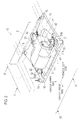
- Fig. 1 is a plan view of a motor supporting structure 10.
- Fig. 2 is a perspective view of the motor supporting structure 10.
- a pair of a right side front side member 1 and a left side front side member 1 extend in a forward-and-backward direction of a vehicle body, where each of the right and left side members 1, 1 is bent or curved such that the rear part of each of the right and left side members 1, 1 is located under a dash panel 2.
- a sub-frame 4 to which a motor 3 for driving a vehicle is mounted, where the sub-frame 4 is square frame-shaped in plan view and is disposed under the front side members 1,1.
- the motor 3 constitutes a rotational driving source of a power train and is disposed in a region which is, when viewed from above the vehicle, surrounded by the square frame-shaped sub-frame 4.
- the square frame-shaped sub-frame 4 has a loop structure formed by providing (connecting) a front cross frame 11 and a rear cross frame 12 each of which extends in a right-and-left direction of the vehicle body and a left side frame 13 and a right side frame 14 each of which extends in the forward-and-backward direction of the vehicle body such that such frames 11, 13, 12 and 14 are linked in series in this order.
- the square frame-shaped sub-frame 4 has four corners, that is, a cross portion between the front cross frame 11 and the left side frame 13, a cross portion between the left side frame 13 and the rear cross frame 12, a cross portion between the rear cross frame 12 and the right side frame 14, and a cross portion between the right side frame 14 and the front cross frame 11, where each of the four corners is elastically supported on a lower face of the front side member 1 by means of an insulator 15.
- the insulators 15 on the four corners are so set that the difference in rigidity between the insulators 15 on right side and the insulators 15 on left side is smaller than the difference in rigidity between the insulators 15 on front side and the insulators 15 on rear side.
- the cross portion is a portion where the front and rear cross frames 11,12 meet the left and right side frames 13, 14.
- the cross portion is defined as an area where an area A1 (where the front cross frame 11 extends in the vehicle right-and-left direction with a width thereof in the vehicle forward-and-backward direction kept) overlaps with an area B1 (where the left side frame 13 extends in the vehicle forward-and-backward direction with a width thereof in the vehicle right-and-left direction kept) when such areas A1 and B1 are viewed from above the vehicle body.
- the cross portion is defined as an area where the area A1 overlaps with an area B2 (where the right side frame 14 extends in the vehicle forward-and-backward direction with a width thereof in the vehicle right-and-left direction kept) when such areas A1 and B2 are viewed from above the vehicle body.
- the cross portion is defined as an area where an area A2 (where the rear cross frame 12 extends in the vehicle right-and-left direction with a width thereof in the vehicle forward-and-backward direction kept) overlaps with the area B1 when such areas A2 and B1 are viewed from above the vehicle body.
- the cross portion is defined as an area where the area A2 overlaps with the area B2 when such areas A2 and B2 are viewed from above the vehicle body.
- the square frame-shaped sub-frame 4 may be formed by forming the front and rear cross frames 11, 12 separately from the left and right side frames 13, 14 and then joining them, or may be formed by forming the front and rear cross frames 11, 12 integrally with the left and right side frames 13, 14.
- a left side face of the motor 3 is elastically supported to the sub-frame 4 by way of a left side bracket 21 and a left side insulator 31 (first motor supporting member).
- a right side face of the motor 3 is elastically supported to the sub-frame 4 by way of a right side bracket 22 and a right side insulator 32 (second motor supporting member).
- a rear side face of the motor 3 is elastically supported to the sub-frame 4 by way of a rear side bracket 23 and a rear side insulator 33 (third motor supporting member).
- the left, right and rear side insulators 31, 32, 33 each have an elastic body and elastically support the motor 3 by means of the elastic body.
- the rear side insulator 33's fixing point to the motor 3 is disposed on an upper side relative to the left and right side insulators 31, 32's fixing points to the motor 3.
- the left side insulator 31 is supported at two points on the front cross frame 11 and left side frame 13 with a first end side flange 31A connected to the front cross frame 11 and a second end side flange 3 1 B connected to the left side frame 13.
- the left side insulator 31 thereby elastically supports the motor 3 between the first end side (first end side flange 31A) and second end side (second end side flange 31B) of the left side insulator 31.
- the left side insulator 31 supports the motor 3 at a position close to the cross portion 16 between the front cross frame 11 and the left side frame 13, that is, on a left end side of the front cross frame 11 and on a front end side of the left side frame 13.
- a rearward protruding portion 41 protruding toward the left side insulator 31, that is, toward inside (vehicle body rear side) of the sub-frame 4, where the first end side flange 31A of the left side insulator 31 is connected to the front cross frame 11 by the rearward protruding portion 41.
- a rightward protruding portion 42 protruding toward the left side insulator 31, that is, toward inside (vehicle body right side) of the sub-frame 4, where the second end side flange 3 1 B of the left side insulator 31 is connected to the left side frame 13 by the rightward protruding portion 42.
- rearward protruding portion 41 may be formed integrally with the front cross frame 11 or may be so formed separately from the front cross frame 11 as to be connected to the front cross frame 11.
- rightward protruding portions 42 may be formed integrally with the left side frame 13 or may be so formed separately from the left side frame 13 as to be connected to the left side frame 13.
- the right side insulator 32 is supported at two points on the front cross frame 11 and right side frame 14 with a first end side flange 32A connected to the front cross frame 11 and a second end side flange 32B connected to the right side frame 14.
- the right side insulator 32 thereby elastically supports the motor 3 between the first end side (first end side flange 32A) and second end side (second end side flange 32B) of the right side insulator 32.
- the right side insulator 32 supports the motor 3 at a position close to the cross portion 17 between the front cross frame 11 and the right side frame 14, that is, on a right end side of the front cross frame 11 and on a front end side of the right side frame 14.
- a rearward protruding portion 43 protruding toward the right side insulator 32, that is, toward inside (vehicle body rear side) of the sub-frame 4, where the first end side flange 32A of the right side insulator 32 is connected to the front cross frame 11 by the rearward protruding portion 43.
- the second end side flange 32B of the right side insulator 32 is connected to the right side frame 14 by the leftward protruding portion 44.
- the rearward protruding portion 43 may be formed integrally with the front cross frame 11 or may be so formed separately from the front cross frame 11 as to be connected to the front cross frame 11.
- the leftward protruding portion 44 may be formed integrally with the right side frame 14 or may be so formed separately from the right side frame 14 as to be connected to the right side frame 14.
- the rear side insulator 33 is to be fixed to a substantially center of the rear cross frame 12.
- the left side insulator 31 is, when viewed from above the vehicle, disposed on one of two ends in the vehicle width direction on the front side of the motor 3, and is disposed in a position closer to the left side frame 13 than to the front cross frame 11.
- the right side insulator 32 is, when viewed from above the vehicle, disposed on another of two ends in the vehicle width direction on the front side of the motor 3, and is disposed in a position closer to the right side frame 14 than to the front cross frame 11.
- the rearward protruding portion 41's connecting portion 41 A connected to the front cross frame 11 is, compared with the rightward protruding portion 42's connecting portion 42A connected to the left side frame 13, disposed in a position closer to the cross portion 16.
- the rearward protruding portion 43's connecting portion 43A connected to the front cross frame 11 is, compared with the leftward protruding portion 44's connecting portion 44A connected to the right side frame 14, disposed in a position closer to the cross portion 17.
- Fig. 3 is a vehicle front view showing the right side bracket 22. That is, Fig. 3 is a cross sectional view which is viewed along the line III-III in Fig. 2 .
- the right side bracket 22 supports a right end portion in the vehicle width direction of the motor 3, instead of supporting a belly portion (lower face) of the motor 3.
- Fig. 4 is a vehicle right side view showing the right side bracket 22. That is, Fig. 4 is a cross sectional view which is viewed along the line IV-IV in Fig. 2 .
- the motor 3 has a motor rotational shaft 3a extending in the vehicle width direction, and the right side bracket 22 (right side insulator 32) supports a part of the right end portion in the vehicle width direction of the motor 3 at a position spaced apart radially from the motor rotational shaft 3a.
- the right side bracket 22 (right side insulator 32) elastically supports a portion of the motor 3 which is on more vehicle body front side than the motor rotational shaft 3 a.
- Fig. 3 and Fig. 4 explain about the right side bracket 22, the same may be likewise applied to the left side bracket 21 (left side insulator 31).
- the vibration of the motor 3 extends to a high frequency range. Therefore, mounting the motor 3 with a mount structure for mounting an engine may excite natural vibrations of the members such as the sub-frame 4, left side frame 13, right side frame 14 and the like in the high frequency range which is not expected to be caused by the engine, thus quality of quietness or vibration damping characteristics, as the case may be, is degraded.
- the motor 3 is elastically supported by way of serially the left side bracket 21 and the left side insulator 31 to the cross portion 16 which is the sub-frame 4's portion having high rigidity. With this, the vibration of the motor 3 is transmitted and dispersed to the front cross frame 11 and to the left side frame 13.
- the motor 3 is elastically supported by way of serially the right side bracket 22 and the right side insulator 32 to the cross portion 17 which is the sub-frame 4's portion having high rigidity. With this, the vibration of the motor 3 is transmitted and dispersed to the front cross frame 11 and to the right side frame 14.
- Fig. 5 shows vibration transmission to the vehicle body.
- Positioning the cross portion 16 close to the insulator 15 allows the left side insulator 31 to be close to the insulator 15. Likewise, positioning the cross portion 17 close to the insulator 15 allows the right side insulator 32 to be close to the insulator 15.
- the two elastic bodies thus positioned close to each other can efficiently absorb the vibration from the motor 3. That is, as shown Fig. 5 , since a double vibration damping effect can be obtained, the vibration transmission to the vehicle body side through the front side member 1 can be suppressed, thus making it possible to prevent the degrading of quality of quietness or vibration damping characteristics.
- the left side insulator 31 is two-point supported in such a manner as to bypass the front cross frame 11 and the left side frame 13, the cross portion 16's bending rigidity in the vehicle vertical direction and the cross portion 16's natural vibration frequency can be increased.
- deformation of each of the front cross frame 11 and left side frame 13 is less likely to be excited, to thereby suppress vibration transmission to the vehicle body side through the front side member 1 and prevent the degrading of quality of quietness or vibration damping characteristics.
- the right side insulator 32 is two-point supported in such a manner as to bypass the front cross frame 11 and the right side frame 14, the cross portion 17's bending rigidity in the vehicle vertical direction and the cross portion 17's natural vibration frequency can be increased.
- deformation of each of the front cross frame 11 and right side frame 14 is less likely to be excited, to thereby suppress vibration transmission to the vehicle body side through the front side member 1 and prevent the degrading of quality of quietness or vibration damping characteristics.
- Downsizing the motor 3 elongates a spaced-apart distance between the motor 3 and the front cross frame 11 and a spaced-apart distance between the motor 3 and the left side frame 13 (right side frame 14). Then, on the left end side (right end side) of the front cross frame 11, there is formed the rearward protruding portion 41 (rearward protruding portion 43) protruding toward the left side insulator 31 (right side insulator 32), while on the front side of the left side frame 13 (right side frame 14), there is formed the rightward protruding portion 42 (leftward protruding portion 44) protruding toward the left side insulator 31 (right side insulator 32).
- the left side insulator 31 is connected to the rearward protruding portion 41 and the rightward protruding portion 42, while the right side insulator 32 is connected to the rearward protruding portion 43 and the leftward protruding portion 44.
- the downsizing of the motor 3 does not need to enlarge the left side bracket 21 (right side bracket 22) or does not need to change the mounting point of the left side insulator 31 (right side insulator 32), to thereby improve convenience.
- enlarging of the left side bracket 21 (right side bracket 22) decreases the effect of suppressing the vibration transmission due to the decrease of rigidity and natural vibration frequency, therefore, preventing enlargement of the left side bracket 21 (right side bracket 22) can prevent the degrading of quality of quietness or vibration damping characteristics.
- the vibration of the motor 3 can be transmitted to the portions having rigidity against the bending mode, thereby suppressing the vibration transmission to the vehicle body member and making it possible to prevent the degrading of quality of quietness or vibration damping characteristics.
- the left side insulator 31 elastically supports the left side of the motor 3 while the right side insulator 32 elastically supports the right side of the motor 3.
- the insulators 15 on the four corners are so set that the difference in rigidity between the insulators 15 on right side and the insulators 15 on left side is smaller than the difference in rigidity between the insulators 15 on front side and the insulators 15 on rear side. Since the left side insulator 31 (right side insulator 32) is disposed close to the insulator 15, a rigidity which is a combination of the rigidity of the insulator 15 and the rigidity of the left side insulator 31 (right side insulator 32) acts on the vehicle body.
- the left side insulator 31 (right side insulator 32) close to the right-and-left insulators 15, 15 having smaller rigidity difference reduces the combined rigidity's difference attributable to the position, where the combined rigidity is a combination of the rigidity of the insulator 15 and the rigidity of the left side insulator 31 (right side insulator 32).
- the combined rigidity is a combination of the rigidity of the insulator 15 and the rigidity of the left side insulator 31 (right side insulator 32).
- the motor 3's rotation axis can be kept parallel to an axis in the vehicle right-and-left direction, whereby operation stability deterioration due to the motor 3's slanting relative to the axis in the vehicle right-and-left direction during the rotation of the motor 3 can be suppressed.
- the vibration mode at which the motor 3 per se vibrates caused by the motor 3's vibration or an external input such as from road surface can be easily controlled, thus making it possible to prevent the degrading of quality of quietness or vibration damping characteristics.
- the left and right side insulators 31, 32 are each disposed on the front side of the motor 3. With this, the left and right side insulators 31, 32 can be fixed to the portions close to the respective cross portions 16,17 where the rigidity is high in the sub-frame 4, thus making it possible to suppress the degrading of quality of quietness or vibration damping characteristics.
- each of the left and right side insulators 31, 32 is disposed on either end side in the vehicle width direction in the motor 3. With this, when the vehicle front portion is deformed backward due to a contact with an obstacle, the left and right side insulators 31, 32's interference with the motor 3 can be prevented. That is, without lowering an effect of absorbing an energy in the contact, the front side member 1 and the sub-frame 4 allow each of the left and right side insulators 31, 32 to effectively absorb the energy at the contact.
- each of the left and right side insulators 31, 32 is disposed in a position closer to the left and right side frames 13, 14 than to the front cross frame 11.
- the front cross frame 11 is, as the case may be, so set for protecting pedestrian that the rigidity of the front cross frame 11 is not too high.
- the left and right side frames 13,14 are higher in rigidity than the front cross frame 11.
- the connecting portions 41A, 43A of the respective rearward protruding portions 41, 43 are, compared with the connecting portions 42A, 44A of the respective rightward and leftward protruding portions 42, 44, disposed closer to the cross portions 16, 17, thus making it possible to suppress the vibration transmission to the front cross frame 11 having a relatively low rigidity.
- the insulators 15 disposed at the cross portions 16, 17 can effectively absorb the vibration.
- the rigidity of the front cross frame 11 can be reduced for protecting pedestrian.
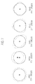
- Fig. 6 is a diagram explaining about a ring mode.
- Fig. 7 is a diagram explaining about drum modes.
- the ring mode and drum mode are vibration modes having a great influence on vehicle noise-vibration performance.
- a ring expands or shrinks; while in the drum mode, a membrane resonance occurs like a drum.
- a position for fixing the right side bracket 22 (mount position) should not be disposed in a belly portion (lower face) of the motor 3.
- a position for fixing the right side bracket 22 (mount position) should not be disposed in the vicinity of the motor rotational shaft 3a.
- the right side bracket 22 at first supports the right end portion in the vehicle width direction (refer to Fig. 3 ). With this, mainly, an influence of the exciting vibration in the drum mode can be relieved. Moreover, the right side bracket 22 supports a part of the right end portion in the vehicle width direction of the motor 3 at the position spaced apart in the radial direction from the motor rotational shaft 3a (refer to Fig. 4 ). With this, mainly, an influence of the exciting vibration in the ring mode can be relieved. In addition, supporting a portion which is on more vehicle body front side than the motor rotational shaft 3a can downsize the right side insulator 32.
- the two insulators (left side insulator 31 and right side insulator 32) which are disposed on the front side of the motor 3 and the one insulator (rear side insulator 33) which is disposed on the rear side of the motor 3 implement mounting of the motor 3 at three portions, thus making it possible to stably support the motor 3.
- the rear side insulator 33's fixing point to the motor 3 is disposed on an upper side relative to the left and right side insulators 31, 32's fixing points to the motor 3.
- the insulators which are supported at two points by the cross frame and the side frame are disposed at two portions, however, the present invention is not limited to this.
- the insulator(s) may be disposed at only one portion or at three portions.
- the motor 3 corresponds to "motor”
- the front side member 1 corresponds to “vehicle body member”
- the front cross frame 11 and the rear cross frame 12 correspond to “cross frame”
- the left side frame 13 and the right side frame 14 correspond to “side frame.”
- the insulator 15 corresponds to "frame supporting member”
- the cross portions 16, 17 correspond to “cross portion”
- the insulators 31, 32 correspond to “motor supporting members”
- the insulator 31 corresponds to "first motor supporting member”
- the insulator 32 corresponds to “second motor supporting member.”
- the rearward protruding portions 41, 43 corresponds to "cross frame side connecting member”
- the rightward protruding portion 42 and the leftward protruding portion 44 each correspond to "side frame side connecting member.”
- the insulator 33 corresponds to "third motor supporting member.”
- a motor supporting structure includes: a vehicle body member which is a part of a vehicle body; a left side frame and a right side frame which extend in a vehicle forward and backward direction below the vehicle body member; a front cross frame and a rear cross frame which extend in a vehicle left and right direction below the vehicle body member and are connected to front end sides and back end sides of the left and right side frames; frame supporting members fixed, when viewed from above the vehicle body to cross portions which are defined as portions where the side frames and the cross frames meet with each other, the frame supporting members being adapted to elastically support the side frames and cross frames by way of elastic bodies included in the frame supporting members; a motor for driving a vehicle which is disposed, when viewed from above the vehicle body, in an area surrounded by the left and right side frames and the front and rear cross frames; a motor supporting member for elastically supporting a front side of the motor by fixing the front side of the motor to a side frame of the side frames and the front cross frame by way of an elastic body included in the motor supporting member; a side
- the vibration of the motor is transmitted and dispersed to the side frames and the cross frame through the motor supporting member, the side frame side connecting member and the cross frame side connecting member, thereby suppressing vibration transmission to the vehicle body member.
- the degrading of quality of quietness or vibration damping characteristics which is observed when the motor instead of an engine is used for driving a vehicle, can be prevented.
- the motor supporting member is disposed, when viewed from above the vehicle body, on the front side of the motor.
- the motor supporting member can be fixed to a position close to the cross portion having high rigidity, thus making it possible to suppress the degrading of quality of quietness or vibration damping characteristics.
- the motor supporting member is disposed, when viewed from above the vehicle body, on one end side of the motor in a vehicle width direction.
- the motor supporting member's interference with the motor 3 can be prevented, that is, without lowering an effect of absorbing an energy in the contact, the vehicle body member, the cross frame and the side frame can effectively absorb the energy at the contact.
- the motor supporting member is disposed in a position closer to the side frame than to the front cross frame.
- a connecting portion of the cross frame side connecting member to the front cross frame is disposed, compared with a connecting portion of the side frame side connecting member to the side frame, in a position closer to a cross portion of the cross portions.
- vibration transmission to the front cross frame having a relatively low rigidity is decreased as much as possible, thereby efficiently transmitting the vibration to the elastic body of the frame supporting member, thus making it possible to efficiently absorb the vibration.
- rigidity of the front cross frame can be reduced for protecting pedestrian.
- the motor has a motor rotational shaft in the vehicle width direction, and the motor supporting member elastically supports a part of an end portion in the vehicle width direction of the motor at a position spaced apart radially from the motor rotational shaft.
- the motor supporting member elastically supports, when viewed from above the vehicle body, a portion of the motor which is on more vehicle body front side than the motor rotational shaft.
- the motor supporting member can be downsized.
- the motor supporting members include: a first motor supporting member fixed to both of the left side frame and the front cross frame, a second motor supporting member fixed to both of the right side frame and the front cross frame, and the motor supporting structure further includes a third motor supporting member which is fixed to the rear cross frame and elastically supports a rear side of the motor by way of an elastic body included in the third motor supporting member.
- a fixing point of the third supporting member to the motor is disposed on an upper side relative to a fixing point of each of the first and second supporting members to the motor.
- the vibration of the motor is transmitted and dispersed to the side frames and the cross frame through the motor supporting members, the side frame side connecting members and the cross frame side connecting members, thereby suppressing vibration transmission to the vehicle body member.
- the degrading of quality of quietness or vibration damping characteristics which is observed when the motor instead of an engine is used for driving a vehicle, can be prevented.
Landscapes
- Engineering & Computer Science (AREA)
- Chemical & Material Sciences (AREA)
- Combustion & Propulsion (AREA)
- Transportation (AREA)
- Mechanical Engineering (AREA)
- Arrangement Or Mounting Of Propulsion Units For Vehicles (AREA)
- Body Structure For Vehicles (AREA)
- Vibration Prevention Devices (AREA)
Abstract
Description
- The present invention relates to a motor supporting structure.
- In a conventional mount structure of a power train including an engine and a transmission, right and left side frames are connected with each other by a front cross member and a suspension cross member and engine mounts disposed at the right and left side frames and suspension cross member support the power train (refer to Patent Literature 1).
-
- [Patent Literature 1] Japanese Patent Application Laid-Open No.
2000-120770 - Compared with vibration of an engine, vibration of a motor extends to a high frequency range. Therefore, mounting a motor with a mount structure for mounting an engine may excite a natural vibrations of the side frame or suspension cross member in the high frequency range which is not expected to be caused by the engine, thus quality of quietness or vibration damping characteristics, as the case may be, is degraded.
- It is an object of the present invention to suppress the degrading of quality of quietness or vibration damping characteristics which may be caused when a motor is adopted for a power train.
- For achieving the above object, a motor supporting structure of the present invention includes: a vehicle body member which is a part of a vehicle body; a left side frame and a right side frame which extend in a vehicle forward and backward direction below the vehicle body member; a front cross frame and a rear cross frame which extend in a vehicle left and right direction below the vehicle body member and are connected to front end sides and back end sides of the left and right side frames; frame supporting members fixed, when viewed from above the vehicle body, to cross portions which are defined as portions where the side frames and the cross frames meet with each other, the frame supporting members being adapted to elastically support the side frames and cross frames by way of elastic bodies included in the frame supporting members; a motor for driving a vehicle which is disposed, when viewed from above the vehicle body, in an area surrounded by the left and right side frames and the front and rear cross frames ; a motor supporting member for elastically supporting a front side of the motor by fixing the front side of the motor to a side frame of the side frames and the front cross frame by way of an elastic body included in the motor supporting member; a side frame side connecting member for connecting the side frame with the motor supporting member, to thereby fix the motor supporting member to the side frame; and a cross frame side connecting member for connecting the front cross frame with the motor supporting member, to thereby fix the motor supporting member to the front cross frame.
- With the motor supporting structure according to the present invention, vibration of a motor is transmitted and dispersed to side frames and a cross frame through motor supporting members, side frame side connecting members and cross frame side connecting members, thereby suppressing vibration transmission to a vehicle body member. Thus, the degrading of quality of quietness or vibration damping characteristics, which is observed when the motor instead of an engine is used for driving a vehicle, can be prevented.
-
- [
Fig. 1] Fig. 1 is a plan view of a motor supporting structure. - [
Fig. 2] Fig. 2 is a perspective view of the motor supporting structure. - [
Fig. 3] Fig. 3 is a vehicle front view showing a right side bracket. - [
Fig. 4] Fig. 4 is a vehicle right side view showing the right side bracket. - [
Fig. 5] Fig. 5 shows vibration transmission to a vehicle body. - [
Fig. 6] Fig. 6 is a diagram explaining about a ring mode. - [
Fig. 7] Fig. 7 is a diagram explaining about drum modes. - Hereinafter, an embodiment of the present invention is to be set forth based on drawing.
-
Fig. 1 is a plan view of amotor supporting structure 10. -
Fig. 2 is a perspective view of themotor supporting structure 10. - A pair of a right side
front side member 1 and a left sidefront side member 1 extend in a forward-and-backward direction of a vehicle body, where each of the right andleft side members left side members sub-frame 4 to which amotor 3 for driving a vehicle is mounted, where thesub-frame 4 is square frame-shaped in plan view and is disposed under thefront side members motor 3 constitutes a rotational driving source of a power train and is disposed in a region which is, when viewed from above the vehicle, surrounded by the square frame-shaped sub-frame 4. - The square frame-
shaped sub-frame 4 has a loop structure formed by providing (connecting) afront cross frame 11 and a rearcross frame 12 each of which extends in a right-and-left direction of the vehicle body and aleft side frame 13 and aright side frame 14 each of which extends in the forward-and-backward direction of the vehicle body such thatsuch frames shaped sub-frame 4 has four corners, that is, a cross portion between thefront cross frame 11 and theleft side frame 13, a cross portion between theleft side frame 13 and therear cross frame 12, a cross portion between the rearcross frame 12 and theright side frame 14, and a cross portion between theright side frame 14 and thefront cross frame 11, where each of the four corners is elastically supported on a lower face of thefront side member 1 by means of aninsulator 15. Theinsulators 15 on the four corners are so set that the difference in rigidity between theinsulators 15 on right side and theinsulators 15 on left side is smaller than the difference in rigidity between theinsulators 15 on front side and theinsulators 15 on rear side. - Herein, the cross portion is a portion where the front and
rear cross frames right side frames cross frame 11 extends in the vehicle right-and-left direction with a width thereof in the vehicle forward-and-backward direction kept) overlaps with an area B1 (where theleft side frame 13 extends in the vehicle forward-and-backward direction with a width thereof in the vehicle right-and-left direction kept) when such areas A1 and B1 are viewed from above the vehicle body. Moreover, the cross portion is defined as an area where the area A1 overlaps with an area B2 (where theright side frame 14 extends in the vehicle forward-and-backward direction with a width thereof in the vehicle right-and-left direction kept) when such areas A1 and B2 are viewed from above the vehicle body. Moreover, the cross portion is defined as an area where an area A2 (where the rearcross frame 12 extends in the vehicle right-and-left direction with a width thereof in the vehicle forward-and-backward direction kept) overlaps with the area B1 when such areas A2 and B1 are viewed from above the vehicle body. Moreover, the cross portion is defined as an area where the area A2 overlaps with the area B2 when such areas A2 and B2 are viewed from above the vehicle body. Moreover, the square frame-shaped sub-frame 4 may be formed by forming the front andrear cross frames right side frames rear cross frames right side frames - A left side face of the
motor 3 is elastically supported to thesub-frame 4 by way of aleft side bracket 21 and a left side insulator 31 (first motor supporting member). Moreover, a right side face of themotor 3 is elastically supported to thesub-frame 4 by way of aright side bracket 22 and a right side insulator 32 (second motor supporting member). Moreover, a rear side face of themotor 3 is elastically supported to thesub-frame 4 by way of arear side bracket 23 and a rear side insulator 33 (third motor supporting member). The left, right andrear side insulators motor 3 by means of the elastic body. Therear side insulator 33's fixing point to themotor 3 is disposed on an upper side relative to the left andright side insulators motor 3. - In plan view, the
left side insulator 31 is supported at two points on thefront cross frame 11 andleft side frame 13 with a firstend side flange 31A connected to thefront cross frame 11 and a secondend side flange 3 1 B connected to theleft side frame 13. Theleft side insulator 31 thereby elastically supports themotor 3 between the first end side (firstend side flange 31A) and second end side (secondend side flange 31B) of theleft side insulator 31. Theleft side insulator 31 supports themotor 3 at a position close to thecross portion 16 between thefront cross frame 11 and theleft side frame 13, that is, on a left end side of thefront cross frame 11 and on a front end side of theleft side frame 13. - On a left end side of the
front cross frame 11, there is formed a rearward protrudingportion 41 protruding toward theleft side insulator 31, that is, toward inside (vehicle body rear side) of thesub-frame 4, where the firstend side flange 31A of theleft side insulator 31 is connected to thefront cross frame 11 by therearward protruding portion 41. On the other hand, on a front end side of theleft side frame 13, there is formed a rightward protrudingportion 42 protruding toward theleft side insulator 31, that is, toward inside (vehicle body right side) of thesub-frame 4, where the secondend side flange 3 1 B of theleft side insulator 31 is connected to theleft side frame 13 by the rightward protrudingportion 42. - In addition, the
rearward protruding portion 41 may be formed integrally with the frontcross frame 11 or may be so formed separately from thefront cross frame 11 as to be connected to thefront cross frame 11. Likewise, the rightward protrudingportions 42 may be formed integrally with theleft side frame 13 or may be so formed separately from theleft side frame 13 as to be connected to theleft side frame 13. - In plan view, the
right side insulator 32 is supported at two points on thefront cross frame 11 andright side frame 14 with a firstend side flange 32A connected to thefront cross frame 11 and a secondend side flange 32B connected to theright side frame 14. Theright side insulator 32 thereby elastically supports themotor 3 between the first end side (firstend side flange 32A) and second end side (secondend side flange 32B) of theright side insulator 32. Theright side insulator 32 supports themotor 3 at a position close to thecross portion 17 between thefront cross frame 11 and theright side frame 14, that is, on a right end side of thefront cross frame 11 and on a front end side of theright side frame 14. - On a right end side of the
front cross frame 11, there is formed a rearward protrudingportion 43 protruding toward theright side insulator 32, that is, toward inside (vehicle body rear side) of thesub-frame 4, where the firstend side flange 32A of theright side insulator 32 is connected to thefront cross frame 11 by the rearwardprotruding portion 43. On the other hand, on a front end side of theright side frame 14, there is formed a leftward protrudingportion 44 protruding toward theright side insulator 32, that is, toward inside (vehicle body left side) of thesub-frame 4, the secondend side flange 32B of theright side insulator 32 is connected to theright side frame 14 by the leftward protrudingportion 44. - In addition, the
rearward protruding portion 43 may be formed integrally with the frontcross frame 11 or may be so formed separately from thefront cross frame 11 as to be connected to thefront cross frame 11. Likewise, the leftwardprotruding portion 44 may be formed integrally with theright side frame 14 or may be so formed separately from theright side frame 14 as to be connected to theright side frame 14. - The
rear side insulator 33 is to be fixed to a substantially center of therear cross frame 12. - Moreover, the
left side insulator 31 is, when viewed from above the vehicle, disposed on one of two ends in the vehicle width direction on the front side of themotor 3, and is disposed in a position closer to theleft side frame 13 than to thefront cross frame 11. Likewise, theright side insulator 32 is, when viewed from above the vehicle, disposed on another of two ends in the vehicle width direction on the front side of themotor 3, and is disposed in a position closer to theright side frame 14 than to thefront cross frame 11. - Moreover, the rearward protruding
portion 41's connecting portion 41 A connected to thefront cross frame 11 is, compared with the rightward protrudingportion 42's connecting portion 42A connected to theleft side frame 13, disposed in a position closer to thecross portion 16. Likewise, the rearwardprotruding portion 43's connecting portion 43A connected to thefront cross frame 11 is, compared with the leftward protrudingportion 44's connecting portion 44A connected to theright side frame 14, disposed in a position closer to thecross portion 17. -
Fig. 3 is a vehicle front view showing theright side bracket 22. That is,Fig. 3 is a cross sectional view which is viewed along the line III-III inFig. 2 . - The
right side bracket 22 supports a right end portion in the vehicle width direction of themotor 3, instead of supporting a belly portion (lower face) of themotor 3. -
Fig. 4 is a vehicle right side view showing theright side bracket 22. That is,Fig. 4 is a cross sectional view which is viewed along the line IV-IV inFig. 2 . - The
motor 3 has a motorrotational shaft 3a extending in the vehicle width direction, and the right side bracket 22 (right side insulator 32) supports a part of the right end portion in the vehicle width direction of themotor 3 at a position spaced apart radially from the motorrotational shaft 3a. Specifically, the right side bracket 22 (right side insulator 32) elastically supports a portion of themotor 3 which is on more vehicle body front side than the motorrotational shaft 3 a. - In addition, although
Fig. 3 and Fig. 4 explain about theright side bracket 22, the same may be likewise applied to the left side bracket 21 (left side insulator 31). - Compared with vibration of an engine, the vibration of the
motor 3 extends to a high frequency range. Therefore, mounting themotor 3 with a mount structure for mounting an engine may excite natural vibrations of the members such as thesub-frame 4,left side frame 13,right side frame 14 and the like in the high frequency range which is not expected to be caused by the engine, thus quality of quietness or vibration damping characteristics, as the case may be, is degraded. - According to the embodiment, the
motor 3 is elastically supported by way of serially theleft side bracket 21 and theleft side insulator 31 to thecross portion 16 which is thesub-frame 4's portion having high rigidity. With this, the vibration of themotor 3 is transmitted and dispersed to thefront cross frame 11 and to theleft side frame 13. Likewise, according to the embodiment, themotor 3 is elastically supported by way of serially theright side bracket 22 and theright side insulator 32 to thecross portion 17 which is thesub-frame 4's portion having high rigidity. With this, the vibration of themotor 3 is transmitted and dispersed to thefront cross frame 11 and to theright side frame 14. Since the vibrations are transmitted to the portions having high rigidity against bending mode, a bending mode deformation in the vehicle vertical direction is less likely to be excited, where such mode is an elastic primary mode of thefront cross frame 11 and left side frame 13 (right side frame 14). That is, the vibration transmission to the vehicle body side through thefront side member 1 is suppressed, thus making it possible to prevent the degrading of quality of quietness or vibration damping characteristics. -
Fig. 5 shows vibration transmission to the vehicle body. - Positioning the
cross portion 16 close to theinsulator 15 allows theleft side insulator 31 to be close to theinsulator 15. Likewise, positioning thecross portion 17 close to theinsulator 15 allows theright side insulator 32 to be close to theinsulator 15. The two elastic bodies thus positioned close to each other can efficiently absorb the vibration from themotor 3. That is, as shownFig. 5 , since a double vibration damping effect can be obtained, the vibration transmission to the vehicle body side through thefront side member 1 can be suppressed, thus making it possible to prevent the degrading of quality of quietness or vibration damping characteristics. - Moreover, since the
left side insulator 31 is two-point supported in such a manner as to bypass thefront cross frame 11 and theleft side frame 13, thecross portion 16's bending rigidity in the vehicle vertical direction and thecross portion 16's natural vibration frequency can be increased. Thus, even when the vibration of themotor 3 is inputted, deformation of each of thefront cross frame 11 andleft side frame 13 is less likely to be excited, to thereby suppress vibration transmission to the vehicle body side through thefront side member 1 and prevent the degrading of quality of quietness or vibration damping characteristics. Likewise, since theright side insulator 32 is two-point supported in such a manner as to bypass thefront cross frame 11 and theright side frame 14, thecross portion 17's bending rigidity in the vehicle vertical direction and thecross portion 17's natural vibration frequency can be increased. Thus, even when the vibration of themotor 3 is inputted, deformation of each of thefront cross frame 11 andright side frame 14 is less likely to be excited, to thereby suppress vibration transmission to the vehicle body side through thefront side member 1 and prevent the degrading of quality of quietness or vibration damping characteristics. - Downsizing the
motor 3 elongates a spaced-apart distance between themotor 3 and thefront cross frame 11 and a spaced-apart distance between themotor 3 and the left side frame 13 (right side frame 14). Then, on the left end side (right end side) of thefront cross frame 11, there is formed the rearward protruding portion 41 (rearward protruding portion 43) protruding toward the left side insulator 31 (right side insulator 32), while on the front side of the left side frame 13 (right side frame 14), there is formed the rightward protruding portion 42 (leftward protruding portion 44) protruding toward the left side insulator 31 (right side insulator 32). Then, theleft side insulator 31 is connected to the rearward protrudingportion 41 and the rightward protrudingportion 42, while theright side insulator 32 is connected to the rearward protrudingportion 43 and the leftward protrudingportion 44. With this, even the downsizing of themotor 3 does not need to enlarge the left side bracket 21 (right side bracket 22) or does not need to change the mounting point of the left side insulator 31 (right side insulator 32), to thereby improve convenience. Especially, enlarging of the left side bracket 21 (right side bracket 22) decreases the effect of suppressing the vibration transmission due to the decrease of rigidity and natural vibration frequency, therefore, preventing enlargement of the left side bracket 21 (right side bracket 22) can prevent the degrading of quality of quietness or vibration damping characteristics. - Moreover, since the left and
right side insulators 31,32 (motor side supporting members) and the insulators 15 (unit body side elastic body) are disposed on a circumference of a rectangle formed by the leftward protruding portion 44 (side frame side connecting member), the rightward protruding portion 42 (side frame side connecting member), the rearward protrudingportions 41, 43 (cross frame side connecting members), theleft side frame 13 and theright side frame 14, thefront cross frame 11 and therear cross frame 12, and the cross portions (16, 17), the vibration of themotor 3 can be transmitted to the portions having rigidity against the bending mode, thereby suppressing the vibration transmission to the vehicle body member and making it possible to prevent the degrading of quality of quietness or vibration damping characteristics. - Moreover, the
left side insulator 31 elastically supports the left side of themotor 3 while theright side insulator 32 elastically supports the right side of themotor 3. Theinsulators 15 on the four corners are so set that the difference in rigidity between theinsulators 15 on right side and theinsulators 15 on left side is smaller than the difference in rigidity between theinsulators 15 on front side and theinsulators 15 on rear side. Since the left side insulator 31 (right side insulator 32) is disposed close to theinsulator 15, a rigidity which is a combination of the rigidity of theinsulator 15 and the rigidity of the left side insulator 31 (right side insulator 32) acts on the vehicle body. Thus, disposing the left side insulator 31 (right side insulator 32) close to the right-and-leftinsulators insulator 15 and the rigidity of the left side insulator 31 (right side insulator 32). Thereby, in terms of supporting rigidity of themotor 3, deviation attributable to the position can be made smaller. Therefore, when themotor 3 rotates, themotor 3's rotation axis can be kept parallel to an axis in the vehicle right-and-left direction, whereby operation stability deterioration due to themotor 3's slanting relative to the axis in the vehicle right-and-left direction during the rotation of themotor 3 can be suppressed. Moreover, the vibration mode at which themotor 3 per se vibrates caused by themotor 3's vibration or an external input such as from road surface can be easily controlled, thus making it possible to prevent the degrading of quality of quietness or vibration damping characteristics. - Moreover, the left and
right side insulators motor 3. With this, the left andright side insulators respective cross portions sub-frame 4, thus making it possible to suppress the degrading of quality of quietness or vibration damping characteristics. - Moreover, each of the left and
right side insulators motor 3. With this, when the vehicle front portion is deformed backward due to a contact with an obstacle, the left andright side insulators motor 3 can be prevented. That is, without lowering an effect of absorbing an energy in the contact, thefront side member 1 and thesub-frame 4 allow each of the left andright side insulators - Moreover, each of the left and
right side insulators front cross frame 11. Thefront cross frame 11 is, as the case may be, so set for protecting pedestrian that the rigidity of thefront cross frame 11 is not too high. In this case, the left and right side frames 13,14 are higher in rigidity than thefront cross frame 11. Thus, disposing the left andright side insulators right side insulators - Moreover, in the
sub-frame 4, the connectingportions portions portions portions cross portions front cross frame 11 having a relatively low rigidity. Thus, theinsulators 15 disposed at thecross portions front cross frame 11 can be reduced for protecting pedestrian. -
Fig. 6 is a diagram explaining about a ring mode. -
Fig. 7 is a diagram explaining about drum modes. - In the
motor 3, the ring mode and drum mode are vibration modes having a great influence on vehicle noise-vibration performance. In the ring mode, a ring expands or shrinks; while in the drum mode, a membrane resonance occurs like a drum. Thus, for avoiding as much as possible the influence by the ring mode, it is preferable that a position for fixing the right side bracket 22 (mount position) should not be disposed in a belly portion (lower face) of themotor 3. Moreover, for avoiding as much as possible the influence by the drum mode, it is preferable that a position for fixing the right side bracket 22 (mount position) should not be disposed in the vicinity of the motorrotational shaft 3a. - Then, the
right side bracket 22 at first supports the right end portion in the vehicle width direction (refer toFig. 3 ). With this, mainly, an influence of the exciting vibration in the drum mode can be relieved. Moreover, theright side bracket 22 supports a part of the right end portion in the vehicle width direction of themotor 3 at the position spaced apart in the radial direction from the motorrotational shaft 3a (refer toFig. 4 ). With this, mainly, an influence of the exciting vibration in the ring mode can be relieved. In addition, supporting a portion which is on more vehicle body front side than the motorrotational shaft 3a can downsize theright side insulator 32. - Moreover, the two insulators (
left side insulator 31 and right side insulator 32) which are disposed on the front side of themotor 3 and the one insulator (rear side insulator 33) which is disposed on the rear side of themotor 3 implement mounting of themotor 3 at three portions, thus making it possible to stably support themotor 3. - Moreover, the
rear side insulator 33's fixing point to themotor 3 is disposed on an upper side relative to the left andright side insulators motor 3. With this, the left andright side insulators motor 3 from the lower side and therear side insulator 33 which supports themotor 3 from the upper side can effectively absorb the vertical vibration of themotor 3. - According to the embodiment, the insulators which are supported at two points by the cross frame and the side frame are disposed at two portions, however, the present invention is not limited to this. The insulator(s) may be disposed at only one portion or at three portions.
- As set forth above, the
motor 3 corresponds to "motor," thefront side member 1 corresponds to "vehicle body member," thefront cross frame 11 and therear cross frame 12 correspond to "cross frame," and theleft side frame 13 and theright side frame 14 correspond to "side frame." Moreover, theinsulator 15 corresponds to "frame supporting member," thecross portions insulators insulator 31 corresponds to "first motor supporting member," and theinsulator 32 corresponds to "second motor supporting member." Moreover, the rearward protrudingportions portion 42 and the leftward protrudingportion 44 each correspond to "side frame side connecting member." Moreover, theinsulator 33 corresponds to "third motor supporting member." - (1) A motor supporting structure includes: a vehicle body member which is a part of a vehicle body; a left side frame and a right side frame which extend in a vehicle forward and backward direction below the vehicle body member; a front cross frame and a rear cross frame which extend in a vehicle left and right direction below the vehicle body member and are connected to front end sides and back end sides of the left and right side frames; frame supporting members fixed, when viewed from above the vehicle body to cross portions which are defined as portions where the side frames and the cross frames meet with each other, the frame supporting members being adapted to elastically support the side frames and cross frames by way of elastic bodies included in the frame supporting members; a motor for driving a vehicle which is disposed, when viewed from above the vehicle body, in an area surrounded by the left and right side frames and the front and rear cross frames; a motor supporting member for elastically supporting a front side of the motor by fixing the front side of the motor to a side frame of the side frames and the front cross frame by way of an elastic body included in the motor supporting member; a side frame side connecting member for connecting the side frame with the motor supporting member, to thereby fix the motor supporting member to the side frame; and a cross frame side connecting member for connecting the front cross frame with the motor supporting member, to thereby fix the motor supporting member to the front cross frame.
- With this, the vibration of the motor is transmitted and dispersed to the side frames and the cross frame through the motor supporting member, the side frame side connecting member and the cross frame side connecting member, thereby suppressing vibration transmission to the vehicle body member. Thus, the degrading of quality of quietness or vibration damping characteristics, which is observed when the motor instead of an engine is used for driving a vehicle, can be prevented.
- (2) The motor supporting member is disposed, when viewed from above the vehicle body, on the front side of the motor.
- With this, the motor supporting member can be fixed to a position close to the cross portion having high rigidity, thus making it possible to suppress the degrading of quality of quietness or vibration damping characteristics.
- (3) The motor supporting member is disposed, when viewed from above the vehicle body, on one end side of the motor in a vehicle width direction.
- With this, when the vehicle front portion has a contact with an obstacle, the motor supporting member's interference with the
motor 3 can be prevented, that is, without lowering an effect of absorbing an energy in the contact, the vehicle body member, the cross frame and the side frame can effectively absorb the energy at the contact. - (4) The motor supporting member is disposed in a position closer to the side frame than to the front cross frame.
- With this, displacement of the motor supporting member can be decreased, thus making it easy to absorb vibration.
- (5) A connecting portion of the cross frame side connecting member to the front cross frame is disposed, compared with a connecting portion of the side frame side connecting member to the side frame, in a position closer to a cross portion of the cross portions.
- With this, vibration transmission to the front cross frame having a relatively low rigidity is decreased as much as possible, thereby efficiently transmitting the vibration to the elastic body of the frame supporting member, thus making it possible to efficiently absorb the vibration. Moreover, rigidity of the front cross frame can be reduced for protecting pedestrian.
- (6) The motor has a motor rotational shaft in the vehicle width direction, and the motor supporting member elastically supports a part of an end portion in the vehicle width direction of the motor at a position spaced apart radially from the motor rotational shaft.
- With this, an exciting vibration's influence caused by deformation of an end portion of the motor in the vehicle width direction or deformation of the other portions of the motor can be prevented, thus making it possible to relieve vibration transmission.
- (7) The motor supporting member elastically supports, when viewed from above the vehicle body, a portion of the motor which is on more vehicle body front side than the motor rotational shaft.
- With this, the motor supporting member can be downsized.
- (8) The motor supporting members include: a first motor supporting member fixed to both of the left side frame and the front cross frame, a second motor supporting member fixed to both of the right side frame and the front cross frame, and the motor supporting structure further includes a third motor supporting member which is fixed to the rear cross frame and elastically supports a rear side of the motor by way of an elastic body included in the third motor supporting member.
- With this, a small number of support members can stably support the motor.
- (9) A fixing point of the third supporting member to the motor is disposed on an upper side relative to a fixing point of each of the first and second supporting members to the motor.
- With this, a vertical vibration of the motor can be effectively absorbed.
- The entire contents of the Japanese Patent Application Laid-Open No.
2009-046945 (filed on February 27, 2009 2009-257850 (filed on November 11, 2009 - With the motor supporting structure according to the present invention, the vibration of the motor is transmitted and dispersed to the side frames and the cross frame through the motor supporting members, the side frame side connecting members and the cross frame side connecting members, thereby suppressing vibration transmission to the vehicle body member. Thus, the degrading of quality of quietness or vibration damping characteristics, which is observed when the motor instead of an engine is used for driving a vehicle, can be prevented.
Claims (9)
- A motor supporting structure comprising:a vehicle body member which is a part or a body;a left side frame and a right side frame which extend in a vehicle forward and backward direction the body member;a front cross frame and a rear cross frame which extend in a left and right direction below the vehicle body member and are connected to front end sides and back end sides of the left and right side frames;frame supporting members fixed, when viewed from the vehicle body, to cross portions which are defined as portions where the side frames and the cross frames meet with, each other, the frame supporting members being adapted to elastically support the side frames and cross frames by way of elastic bodies in the frame supporting members;a motor for driving a vehicle which is disposed, when viewed from above the vehicle body, in an area surrounded by the left and right side frames and the front and rear cross frames;a motor supporting member for elastically supporting a front side of the motor by fixing the front side of the motor to a side frame of the side frames and the front cross frame by way of an elastic body included in the motor supporting member;a side frame side connecting member for connecting the side frame with he motor supporting member, to thereby fix the motor supporting member to the side frame; anda cross frame side connecting member for connecting the front cross frame with the motor supporting member, to thereby fix the motor supporting member to the front cross frame.
- The motor supporting structure according to claim 1 wherein the motor supporting member is disposed, when viewed from above the vehicle body, on the front side of the motor.
- The motor supporting structure according to claim 1 or 2 wherein the motor supporting member is disposed, when viewed from above the vehicle body, on one end side of the motor in a vehicle width direction.
- The motor supporting structure according to any one of claims 1 to 3 wherein the motor supporting member is disposed in a position closer to the side frame than to the front cross frame.
- The motor supporting structure according to any one of claims 1 to 4 wherein a connecting portion of the cross frame side connecting member to the front cross frame is disposed, compared with a connecting portion of the side frame side connecting member to the side frame, in a position closer to a cross portion of the cross portions.
- The motor supporting structure according to any one of claims 1 to 5 wherein
the motor has a motor rotational shaft in the vehicle width direction, and
the motor supporting member elastically supports a part of an end portion in the vehicle width direction of the motor at a position spaced apart radially from the motor rotational shaft. - The motor supporting structure according to claim 6 wherein the motor supporting member elastically supports, when viewed from above the vehicle body, a portion of the motor which is on more vehicle body front side than the motor rotational shaft.
- The motor supporting structure according to any one of claims 1 to 7 wherein the motor supporting members include:a first motor supporting member fixed to both of the left side frame and the front cross frame,a second motor supporting member fixed to both of the right side frame and the front cross frame, andthe motor supporting structure further includes a third motor supporting member which is fixed to the rear cross frame and elastically supports a rear side of the motor by way of an elastic body included in the third motor supporting member.
- The motor supporting structure according to claim 8 wherein a fixing point of the third supporting member to the motor is disposed on an upper side relative to a fixing point of each of the first and second supporting members to the motor.
Applications Claiming Priority (3)
| Application Number | Priority Date | Filing Date | Title |
|---|---|---|---|
| JP2009046945 | 2009-02-27 | ||
| JP2009257850A JP4930576B2 (en) | 2009-02-27 | 2009-11-11 | Motor support structure |
| PCT/JP2010/051043 WO2010098165A1 (en) | 2009-02-27 | 2010-01-27 | Motor support structure |
Publications (3)
| Publication Number | Publication Date |
|---|---|
| EP2402190A1 true EP2402190A1 (en) | 2012-01-04 |
| EP2402190A4 EP2402190A4 (en) | 2012-10-24 |
| EP2402190B1 EP2402190B1 (en) | 2014-03-12 |
Family
ID=42665375
Family Applications (1)
| Application Number | Title | Priority Date | Filing Date |
|---|---|---|---|
| EP10746046.1A Not-in-force EP2402190B1 (en) | 2009-02-27 | 2010-01-27 | Motor support structure |
Country Status (5)
| Country | Link |
|---|---|
| US (1) | US8511416B2 (en) |
| EP (1) | EP2402190B1 (en) |
| JP (1) | JP4930576B2 (en) |
| CN (1) | CN102300733B (en) |
| WO (1) | WO2010098165A1 (en) |
Cited By (5)
| Publication number | Priority date | Publication date | Assignee | Title |
|---|---|---|---|---|
| CN106533016A (en) * | 2016-11-11 | 2017-03-22 | 合肥德通电驱动系统有限公司 | Portable installation bracket device for motor |
| FR3047446A1 (en) * | 2016-02-09 | 2017-08-11 | Peugeot Citroen Automobiles Sa | SYSTEM FOR THE SUSPENSION OF A DOUBLE-FILTRATION AND DOUBLE-DECOUPLING ELECTRIC MOTOR MACHINE FOR A VEHICLE |
| WO2019091815A1 (en) * | 2017-11-10 | 2019-05-16 | Volkswagen Aktiengesellschaft | Front axle supporting frame comprising a mounting device for a drive unit |
| FR3089885A1 (en) * | 2018-12-18 | 2020-06-19 | Psa Automobiles Sa | VEHICLE DRIVE UNIT WITH DRIVE ELECTRIC MACHINE SUPPORTED BY A STRUCTURAL ELEMENT AND COUPLED TO A CROSSBAR |
| FR3159770A1 (en) * | 2024-03-04 | 2025-09-05 | Stellantis Auto Sas | ELECTRIC OR HYBRID MOTOR VEHICLE COMPRISING AN AXLE COMPRISING AN UPPER PART AND A LOWER PART |
Families Citing this family (42)
| Publication number | Priority date | Publication date | Assignee | Title |
|---|---|---|---|---|
| JP5435235B2 (en) * | 2010-04-28 | 2014-03-05 | スズキ株式会社 | Support device for vehicle powertrain |
| US8991535B2 (en) * | 2011-11-08 | 2015-03-31 | Electric Motor Werks, Inc. | Modular, customizable and scalable mechanical design for the electric car assembly based on the existing vehicle chassis |
| JP5929435B2 (en) * | 2012-04-04 | 2016-06-08 | スズキ株式会社 | Hybrid vehicle power unit |
| US9340229B2 (en) * | 2012-05-21 | 2016-05-17 | Magna International Inc. | Cradle assembly for a vehicle |
| DE102012012327B4 (en) * | 2012-06-20 | 2026-02-26 | Volkswagen Aktiengesellschaft | Arrangement of an electric motor unit in the engine compartment of a motor vehicle |
| US11352062B2 (en) | 2012-12-21 | 2022-06-07 | Dr. Ing. H. C. F. Porsche Ag | Subframe for holding an electric energy accumulator in a motor vehicle |
| DE102012112966B4 (en) * | 2012-12-21 | 2025-08-14 | Dr. Ing. H.C. F. Porsche Aktiengesellschaft | Subframe for accommodating an electrical energy storage device in a motor vehicle |
| EP2977251A1 (en) * | 2013-03-18 | 2016-01-27 | Hitachi Automotive Systems, Ltd. | Drive device for electric vehicle |
| US9045172B2 (en) * | 2013-07-25 | 2015-06-02 | Ford Global Technologies, Llc | Powertrain catcher bracket |
| DE102013217368A1 (en) * | 2013-08-30 | 2015-03-05 | Hamm Ag | Drive assembly, in particular for a construction machine, subassembly for a drive assembly and this comprehensive construction machine |
| US9637172B2 (en) * | 2013-11-12 | 2017-05-02 | Nissan Motor Co., Ltd. | Vehicle body structure for automobile |
| AU2014370931A1 (en) * | 2013-12-27 | 2016-07-14 | Honda Motor Co.,Ltd. | Sub-frame structure |
| JP6455654B2 (en) * | 2014-03-26 | 2019-01-23 | 三菱自動車工業株式会社 | Vehicle power plant mounting structure |
| GB2524990A (en) * | 2014-04-08 | 2015-10-14 | Bentley Motors Ltd | Mounting structure for an engine mount and method |
| EP3169542A1 (en) * | 2014-07-15 | 2017-05-24 | Carrier Corporation | Transport refrigeration unit and method of driving a compressor |
| CN104260629B (en) * | 2014-09-19 | 2016-08-31 | 南京金龙客车制造有限公司 | A kind of automobile drive electric motor mounting structure |
| US9676415B2 (en) * | 2015-03-13 | 2017-06-13 | GM Global Technology Operations LLC | Rear drive module assembly and system for mounting to a vehicle |
| CA2972285C (en) * | 2015-03-26 | 2018-08-14 | Services Automobiles Grantuned Inc. | A fuel to electric reusable conversion kit and a method of converting and reusing the conversion kit |
| US9874264B2 (en) * | 2015-11-18 | 2018-01-23 | Toyota Motor Engineering & Manufacturing North America, Inc. | Magnetic field activated powertrain mount |
| WO2018065677A1 (en) * | 2016-10-06 | 2018-04-12 | Cooper Standard France | Anti-vibratory support for a motor vehicle and motor vehicle equipped with same |
| JP6447642B2 (en) * | 2017-01-16 | 2019-01-09 | マツダ株式会社 | Electric vehicle |
| JP6481704B2 (en) * | 2017-03-27 | 2019-03-13 | マツダ株式会社 | Front subframe structure |
| CN107235079B (en) * | 2017-06-23 | 2020-08-04 | 奇瑞汽车股份有限公司 | Shock-absorbing structure of auxiliary frame |
| FR3068649B1 (en) * | 2017-07-10 | 2021-11-26 | Renault Sas | MONOBLOC SUPPORT DEVICE FOR A POWERTRAIN UNIT INTEGRATING A RELAY BEARING |
| CN107839460B (en) * | 2017-10-24 | 2020-09-04 | 奇瑞汽车股份有限公司 | Automobile front and rear suspension arrangement scheme |
| JP2019130979A (en) * | 2018-01-30 | 2019-08-08 | Ntn株式会社 | Suspension structure for in-wheel motor drive device |
| DE102018105593A1 (en) * | 2018-03-12 | 2019-09-12 | Man Truck & Bus Ag | Arrangement for drive storage |
| US10336173B1 (en) * | 2018-03-27 | 2019-07-02 | Kawasaki Jukogyo Kabushiki Kaisha | Mounting structure for power unit of utility vehicle |
| DE102018214287A1 (en) * | 2018-08-23 | 2020-02-27 | Bayerische Motoren Werke Aktiengesellschaft | Axle of a vehicle |
| JP6740314B2 (en) * | 2018-10-05 | 2020-08-12 | 本田技研工業株式会社 | vehicle |
| CN109435659B (en) * | 2018-11-20 | 2020-11-17 | 浙江吉利汽车研究院有限公司 | Electric automobile power assembly suspension system and car |
| CN109693526A (en) * | 2019-02-01 | 2019-04-30 | 中国第一汽车股份有限公司 | Pure electric automobile power assembly suspension system |
| JP7307893B2 (en) * | 2019-05-30 | 2023-07-13 | マツダ株式会社 | Vehicle powertrain support structure |
| JP7281102B2 (en) * | 2019-05-30 | 2023-05-25 | マツダ株式会社 | VEHICLE POWERTRAIN SUPPORT METHOD AND SUPPORT STRUCTURE |
| US11453440B2 (en) * | 2020-03-18 | 2022-09-27 | Volvo Car Corporation | Subframe assembly for a vehicle |
| KR20230026195A (en) * | 2021-08-17 | 2023-02-24 | 현대자동차주식회사 | Electric vehicle structure |
| EP4434789A4 (en) * | 2021-11-17 | 2025-02-26 | Nissan Motor Co., Ltd. | Motor mount system |
| KR102696088B1 (en) * | 2022-04-06 | 2024-08-16 | 한국자동차연구원 | Motor assembly for converting engine vehicle into electric vehicle and installation method thereof |
| US12291267B2 (en) * | 2023-01-05 | 2025-05-06 | Arctic Cat Inc. | Off-road vehicle engine mounting |
| JP7845299B2 (en) * | 2023-07-14 | 2026-04-14 | トヨタ自動車株式会社 | Engine compartment mounting structure |
| CN116654095B (en) * | 2023-07-28 | 2023-10-13 | 昆山美仑工业样机有限公司 | New energy automobile frame based on motor suspension structure and stability enhancement method thereof |
| FR3161154A1 (en) * | 2024-04-11 | 2025-10-17 | Stellantis Auto Sas | SUPPORT MODULE FOR SUSPENSION WEDGES AND STABILIZER BAR BEARING |
Family Cites Families (46)
| Publication number | Priority date | Publication date | Assignee | Title |
|---|---|---|---|---|
| JPS61181779A (en) * | 1985-02-06 | 1986-08-14 | Mazda Motor Corp | Subframe of automobile |
| JP2657319B2 (en) | 1989-08-08 | 1997-09-24 | 本田技研工業株式会社 | Automobile power unit support device |
| US5096010A (en) * | 1990-12-19 | 1992-03-17 | Ford Motor Company | Subframe induction noise reduction side-branch reactive silencer |
| JP2650167B2 (en) * | 1991-06-24 | 1997-09-03 | 日産自動車株式会社 | Automotive power plant support equipment |
| JP3150758B2 (en) | 1992-05-26 | 2001-03-26 | マツダ株式会社 | Motor mount structure for electric vehicles |
| JPH0781429A (en) | 1993-09-16 | 1995-03-28 | Nissan Motor Co Ltd | Auxiliary equipment drive for electric vehicles |
| JPH07117725A (en) | 1993-10-22 | 1995-05-09 | Nissan Motor Co Ltd | Electric vehicle body front structure |
| JP3003485B2 (en) | 1993-12-07 | 2000-01-31 | 日産自動車株式会社 | Motor unit support structure for electric vehicles |
| JP3214220B2 (en) | 1994-04-11 | 2001-10-02 | 日産自動車株式会社 | Drive motor mounting structure for electric vehicles |
| JPH08310252A (en) | 1995-05-17 | 1996-11-26 | Nissan Motor Co Ltd | Mounting structure and mounting method for parts in motor room of electric vehicle |
| JP3375788B2 (en) | 1995-06-09 | 2003-02-10 | ダイハツ工業株式会社 | Electric vehicle power unit |
| JPH09150635A (en) | 1995-11-28 | 1997-06-10 | Meidensha Corp | Mounting structure for electric vehicle driving device |
| JP3674145B2 (en) | 1996-04-05 | 2005-07-20 | トヨタ自動車株式会社 | Electric vehicle body front structure |
| JP3584684B2 (en) * | 1997-06-20 | 2004-11-04 | トヨタ自動車株式会社 | Suspension system for vehicle engine |
| JP3464756B2 (en) * | 1997-12-12 | 2003-11-10 | 本田技研工業株式会社 | Impact absorbing body structure for vehicles |
| JP2000120770A (en) | 1998-10-08 | 2000-04-25 | Fuji Heavy Ind Ltd | Automotive anti-vibration device |
| JP3533979B2 (en) * | 1999-03-05 | 2004-06-07 | 日産自動車株式会社 | Power head mounting structure for electric vehicles |
| JP2001105893A (en) | 1999-10-07 | 2001-04-17 | Suzuki Motor Corp | Electric car |
| JP3578087B2 (en) * | 2001-01-19 | 2004-10-20 | 日産自動車株式会社 | Automotive power unit layout |
| JP2002274195A (en) * | 2001-03-21 | 2002-09-25 | Nissan Motor Co Ltd | Vehicle subframe support device |
| US6708793B2 (en) * | 2001-05-11 | 2004-03-23 | General Motors Corporation | Double-isolated, symmetric, high-damped mount system |
| JP4736245B2 (en) | 2001-06-15 | 2011-07-27 | トヨタ自動車株式会社 | Electric vehicle and its assembly method |
| JP3606250B2 (en) * | 2001-10-29 | 2005-01-05 | 日産自動車株式会社 | Body front structure |
| DE10235110A1 (en) * | 2002-08-01 | 2004-02-19 | Audi Ag | Subframes for motor vehicles |
| JP2004100789A (en) * | 2002-09-06 | 2004-04-02 | Honda Motor Co Ltd | Vehicle power source mounting structure |
| JP4026815B2 (en) * | 2002-09-06 | 2007-12-26 | 本田技研工業株式会社 | Subframe mounting structure |
| JP3949549B2 (en) * | 2002-09-06 | 2007-07-25 | 本田技研工業株式会社 | Vehicle transmission mount structure |
| JP2004148843A (en) * | 2002-09-06 | 2004-05-27 | Honda Motor Co Ltd | Vehicle power source support structure |
| JP4321199B2 (en) * | 2002-10-21 | 2009-08-26 | 日産自動車株式会社 | Drive motor mounting structure |
| TWI259815B (en) * | 2002-11-07 | 2006-08-11 | Mitsubishi Motors Corp | Power plant mounting apparatus |
| JP2004276764A (en) * | 2003-03-17 | 2004-10-07 | Honda Motor Co Ltd | Engine suspension for vehicles |
| JP2004314803A (en) | 2003-04-16 | 2004-11-11 | Nissan Motor Co Ltd | Mounting structure of drive motor for electric vehicle |
| DE10329037A1 (en) * | 2003-06-27 | 2005-01-13 | Audi Ag | Method and device for vibration damping |
| WO2005030516A1 (en) * | 2003-09-29 | 2005-04-07 | Nissan Motor Co., Ltd. | Drive motor fixing structure and fixing method |
| JP4367077B2 (en) * | 2003-10-09 | 2009-11-18 | 日産自動車株式会社 | Drive motor mounting structure |
| US7108098B2 (en) * | 2004-06-30 | 2006-09-19 | Cnh America Llc | Engine subframe mounting arrangement |
| JP2006088871A (en) | 2004-09-24 | 2006-04-06 | Nissan Motor Co Ltd | Electric vehicle power unit mounting structure |
| JP2006117011A (en) | 2004-10-19 | 2006-05-11 | Nissan Motor Co Ltd | Independent drive electric vehicle |
| KR100610123B1 (en) * | 2004-12-21 | 2006-08-09 | 현대자동차주식회사 | Automotive power train mounting system |
| JP4276185B2 (en) * | 2005-01-26 | 2009-06-10 | 本田技研工業株式会社 | Body front structure |
| JP2007022276A (en) | 2005-07-15 | 2007-02-01 | Nissan Motor Co Ltd | Electric vehicle motor mount |
| JP4383426B2 (en) * | 2006-05-08 | 2009-12-16 | 本田技研工業株式会社 | Power unit support device for vehicle |
| JP2007331634A (en) | 2006-06-16 | 2007-12-27 | Nissan Motor Co Ltd | Electric vehicle motor room component mounting structure |
| JP4893166B2 (en) * | 2006-08-29 | 2012-03-07 | トヨタ自動車株式会社 | Support stiffness variable mount device and variable stiffness mount |
| JP5325653B2 (en) * | 2009-05-19 | 2013-10-23 | 東海ゴム工業株式会社 | Drive unit anti-vibration holding device for electric motor drive type vehicle |
| JP5522118B2 (en) * | 2011-05-19 | 2014-06-18 | トヨタ自動車株式会社 | Motor mounting structure |
-
2009
- 2009-11-11 JP JP2009257850A patent/JP4930576B2/en not_active Expired - Fee Related
-
2010
- 2010-01-27 US US13/203,120 patent/US8511416B2/en not_active Expired - Fee Related
- 2010-01-27 EP EP10746046.1A patent/EP2402190B1/en not_active Not-in-force
- 2010-01-27 WO PCT/JP2010/051043 patent/WO2010098165A1/en not_active Ceased
- 2010-01-27 CN CN201080005547.0A patent/CN102300733B/en not_active Expired - Fee Related
Cited By (7)
| Publication number | Priority date | Publication date | Assignee | Title |
|---|---|---|---|---|
| FR3047446A1 (en) * | 2016-02-09 | 2017-08-11 | Peugeot Citroen Automobiles Sa | SYSTEM FOR THE SUSPENSION OF A DOUBLE-FILTRATION AND DOUBLE-DECOUPLING ELECTRIC MOTOR MACHINE FOR A VEHICLE |
| CN106533016A (en) * | 2016-11-11 | 2017-03-22 | 合肥德通电驱动系统有限公司 | Portable installation bracket device for motor |
| WO2019091815A1 (en) * | 2017-11-10 | 2019-05-16 | Volkswagen Aktiengesellschaft | Front axle supporting frame comprising a mounting device for a drive unit |
| CN111315641A (en) * | 2017-11-10 | 2020-06-19 | 大众汽车有限公司 | Front axle subframe with bearing for a drive unit |
| US11279407B2 (en) | 2017-11-10 | 2022-03-22 | Volkswagen Aktiengesellschaft | Front axle supporting frame comprising a mounting device for a drive unit |
| FR3089885A1 (en) * | 2018-12-18 | 2020-06-19 | Psa Automobiles Sa | VEHICLE DRIVE UNIT WITH DRIVE ELECTRIC MACHINE SUPPORTED BY A STRUCTURAL ELEMENT AND COUPLED TO A CROSSBAR |
| FR3159770A1 (en) * | 2024-03-04 | 2025-09-05 | Stellantis Auto Sas | ELECTRIC OR HYBRID MOTOR VEHICLE COMPRISING AN AXLE COMPRISING AN UPPER PART AND A LOWER PART |
Also Published As
| Publication number | Publication date |
|---|---|
| JP4930576B2 (en) | 2012-05-16 |
| WO2010098165A1 (en) | 2010-09-02 |
| EP2402190B1 (en) | 2014-03-12 |
| CN102300733B (en) | 2014-04-09 |
| US20110308877A1 (en) | 2011-12-22 |
| JP2010221992A (en) | 2010-10-07 |
| CN102300733A (en) | 2011-12-28 |
| EP2402190A4 (en) | 2012-10-24 |
| US8511416B2 (en) | 2013-08-20 |
Similar Documents
| Publication | Publication Date | Title |
|---|---|---|
| US8511416B2 (en) | Motor supporting structure | |
| CN108725189B (en) | Support structure for vehicle drive system unit | |
| US7232005B2 (en) | Power plant mounting apparatus | |
| JP2000240723A (en) | Rotating device support structure and fuel supply device using the same | |
| JP4296987B2 (en) | Engine mount structure | |
| CN110356215A (en) | The supporting construction of driving source | |
| WO2023120252A1 (en) | Mount bracket | |
| JP2017036032A (en) | Work vehicle | |
| JP5533779B2 (en) | Rear structure of the vehicle | |
| JP2022163984A (en) | drive motor module | |
| JP6245021B2 (en) | Auxiliary machine mounting structure | |
| US20050211492A1 (en) | Power train supporting apparatus and method for automotive vehicle | |
| US20190040930A1 (en) | Noise vibration energy damping structure in vehicle | |
| US10882386B2 (en) | Powertrain mount structure of vehicle | |
| US7874394B2 (en) | Industrial truck with a preassembled axle assembly | |
| JP2009012509A (en) | Cab mount structure | |
| JP7735959B2 (en) | Vehicle vibration isolation structure | |
| JP4923898B2 (en) | Mounting system | |
| JP2016210343A (en) | Vibration isolation structure of construction machine | |
| JP6897506B2 (en) | mount | |
| JP4487693B2 (en) | Engine mount device | |
| US10843546B2 (en) | Fastening system for fastening a drive unit to a vehicle body | |
| JPH11263130A (en) | Engine mount bracket structure | |
| JP4244373B2 (en) | Vehicle powertrain support structure | |
| JP2007106162A (en) | Automotive internal combustion engine support structure |
Legal Events
| Date | Code | Title | Description |
|---|---|---|---|
| PUAI | Public reference made under article 153(3) epc to a published international application that has entered the european phase |
Free format text: ORIGINAL CODE: 0009012 |
|
| 17P | Request for examination filed |
Effective date: 20110921 |
|
| AK | Designated contracting states |
Kind code of ref document: A1 Designated state(s): AT BE BG CH CY CZ DE DK EE ES FI FR GB GR HR HU IE IS IT LI LT LU LV MC MK MT NL NO PL PT RO SE SI SK SM TR |
|
| DAX | Request for extension of the european patent (deleted) | ||
| A4 | Supplementary search report drawn up and despatched |
Effective date: 20120925 |
|
| RIC1 | Information provided on ipc code assigned before grant |
Ipc: B62D 21/00 20060101ALI20120919BHEP Ipc: B62D 21/11 20060101ALI20120919BHEP Ipc: B60K 1/00 20060101AFI20120919BHEP Ipc: H02K 5/24 20060101ALI20120919BHEP Ipc: H02K 5/00 20060101ALI20120919BHEP |
|
| GRAP | Despatch of communication of intention to grant a patent |
Free format text: ORIGINAL CODE: EPIDOSNIGR1 |
|
| RIC1 | Information provided on ipc code assigned before grant |
Ipc: B62D 21/00 20060101ALI20130917BHEP Ipc: H02K 5/24 20060101ALI20130917BHEP Ipc: B62D 21/11 20060101ALI20130917BHEP Ipc: B60K 1/00 20060101AFI20130917BHEP Ipc: H02K 5/00 20060101ALI20130917BHEP |
|
| INTG | Intention to grant announced |
Effective date: 20131009 |
|
| GRAS | Grant fee paid |
Free format text: ORIGINAL CODE: EPIDOSNIGR3 |
|
| GRAA | (expected) grant |
Free format text: ORIGINAL CODE: 0009210 |
|
| AK | Designated contracting states |
Kind code of ref document: B1 Designated state(s): AT BE BG CH CY CZ DE DK EE ES FI FR GB GR HR HU IE IS IT LI LT LU LV MC MK MT NL NO PL PT RO SE SI SK SM TR |
|
| REG | Reference to a national code |
Ref country code: GB Ref legal event code: FG4D |
|
| REG | Reference to a national code |
Ref country code: CH Ref legal event code: EP |
|
| REG | Reference to a national code |
Ref country code: AT Ref legal event code: REF Ref document number: 656032 Country of ref document: AT Kind code of ref document: T Effective date: 20140315 |
|
| REG | Reference to a national code |
Ref country code: IE Ref legal event code: FG4D |
|
| REG | Reference to a national code |
Ref country code: DE Ref legal event code: R096 Ref document number: 602010014247 Country of ref document: DE Effective date: 20140424 |
|
| REG | Reference to a national code |
Ref country code: NL Ref legal event code: VDEP Effective date: 20140312 |
|
| PG25 | Lapsed in a contracting state [announced via postgrant information from national office to epo] |
Ref country code: LT Free format text: LAPSE BECAUSE OF FAILURE TO SUBMIT A TRANSLATION OF THE DESCRIPTION OR TO PAY THE FEE WITHIN THE PRESCRIBED TIME-LIMIT Effective date: 20140312 Ref country code: NO Free format text: LAPSE BECAUSE OF FAILURE TO SUBMIT A TRANSLATION OF THE DESCRIPTION OR TO PAY THE FEE WITHIN THE PRESCRIBED TIME-LIMIT Effective date: 20140612 |
|
| REG | Reference to a national code |
Ref country code: AT Ref legal event code: MK05 Ref document number: 656032 Country of ref document: AT Kind code of ref document: T Effective date: 20140312 |
|
| REG | Reference to a national code |
Ref country code: LT Ref legal event code: MG4D |
|
| PG25 | Lapsed in a contracting state [announced via postgrant information from national office to epo] |
Ref country code: SE Free format text: LAPSE BECAUSE OF FAILURE TO SUBMIT A TRANSLATION OF THE DESCRIPTION OR TO PAY THE FEE WITHIN THE PRESCRIBED TIME-LIMIT Effective date: 20140312 Ref country code: CY Free format text: LAPSE BECAUSE OF FAILURE TO SUBMIT A TRANSLATION OF THE DESCRIPTION OR TO PAY THE FEE WITHIN THE PRESCRIBED TIME-LIMIT Effective date: 20140312 Ref country code: FI Free format text: LAPSE BECAUSE OF FAILURE TO SUBMIT A TRANSLATION OF THE DESCRIPTION OR TO PAY THE FEE WITHIN THE PRESCRIBED TIME-LIMIT Effective date: 20140312 |
|
| PG25 | Lapsed in a contracting state [announced via postgrant information from national office to epo] |
Ref country code: HR Free format text: LAPSE BECAUSE OF FAILURE TO SUBMIT A TRANSLATION OF THE DESCRIPTION OR TO PAY THE FEE WITHIN THE PRESCRIBED TIME-LIMIT Effective date: 20140312 Ref country code: LV Free format text: LAPSE BECAUSE OF FAILURE TO SUBMIT A TRANSLATION OF THE DESCRIPTION OR TO PAY THE FEE WITHIN THE PRESCRIBED TIME-LIMIT Effective date: 20140312 |
|
| PG25 | Lapsed in a contracting state [announced via postgrant information from national office to epo] |
Ref country code: NL Free format text: LAPSE BECAUSE OF FAILURE TO SUBMIT A TRANSLATION OF THE DESCRIPTION OR TO PAY THE FEE WITHIN THE PRESCRIBED TIME-LIMIT Effective date: 20140312 Ref country code: RO Free format text: LAPSE BECAUSE OF FAILURE TO SUBMIT A TRANSLATION OF THE DESCRIPTION OR TO PAY THE FEE WITHIN THE PRESCRIBED TIME-LIMIT Effective date: 20140312 Ref country code: CZ Free format text: LAPSE BECAUSE OF FAILURE TO SUBMIT A TRANSLATION OF THE DESCRIPTION OR TO PAY THE FEE WITHIN THE PRESCRIBED TIME-LIMIT Effective date: 20140312 Ref country code: BE Free format text: LAPSE BECAUSE OF FAILURE TO SUBMIT A TRANSLATION OF THE DESCRIPTION OR TO PAY THE FEE WITHIN THE PRESCRIBED TIME-LIMIT Effective date: 20140312 Ref country code: IS Free format text: LAPSE BECAUSE OF FAILURE TO SUBMIT A TRANSLATION OF THE DESCRIPTION OR TO PAY THE FEE WITHIN THE PRESCRIBED TIME-LIMIT Effective date: 20140712 Ref country code: EE Free format text: LAPSE BECAUSE OF FAILURE TO SUBMIT A TRANSLATION OF THE DESCRIPTION OR TO PAY THE FEE WITHIN THE PRESCRIBED TIME-LIMIT Effective date: 20140312 Ref country code: BG Free format text: LAPSE BECAUSE OF FAILURE TO SUBMIT A TRANSLATION OF THE DESCRIPTION OR TO PAY THE FEE WITHIN THE PRESCRIBED TIME-LIMIT Effective date: 20140612 |
|
| PG25 | Lapsed in a contracting state [announced via postgrant information from national office to epo] |
Ref country code: ES Free format text: LAPSE BECAUSE OF FAILURE TO SUBMIT A TRANSLATION OF THE DESCRIPTION OR TO PAY THE FEE WITHIN THE PRESCRIBED TIME-LIMIT Effective date: 20140312 Ref country code: SK Free format text: LAPSE BECAUSE OF FAILURE TO SUBMIT A TRANSLATION OF THE DESCRIPTION OR TO PAY THE FEE WITHIN THE PRESCRIBED TIME-LIMIT Effective date: 20140312 Ref country code: AT Free format text: LAPSE BECAUSE OF FAILURE TO SUBMIT A TRANSLATION OF THE DESCRIPTION OR TO PAY THE FEE WITHIN THE PRESCRIBED TIME-LIMIT Effective date: 20140312 Ref country code: PL Free format text: LAPSE BECAUSE OF FAILURE TO SUBMIT A TRANSLATION OF THE DESCRIPTION OR TO PAY THE FEE WITHIN THE PRESCRIBED TIME-LIMIT Effective date: 20140312 |
|
| REG | Reference to a national code |
Ref country code: DE Ref legal event code: R097 Ref document number: 602010014247 Country of ref document: DE |
|
| PG25 | Lapsed in a contracting state [announced via postgrant information from national office to epo] |
Ref country code: PT Free format text: LAPSE BECAUSE OF FAILURE TO SUBMIT A TRANSLATION OF THE DESCRIPTION OR TO PAY THE FEE WITHIN THE PRESCRIBED TIME-LIMIT Effective date: 20140714 |
|
| PLBE | No opposition filed within time limit |
Free format text: ORIGINAL CODE: 0009261 |
|
| STAA | Information on the status of an ep patent application or granted ep patent |
Free format text: STATUS: NO OPPOSITION FILED WITHIN TIME LIMIT |
|
| PG25 | Lapsed in a contracting state [announced via postgrant information from national office to epo] |
Ref country code: DK Free format text: LAPSE BECAUSE OF FAILURE TO SUBMIT A TRANSLATION OF THE DESCRIPTION OR TO PAY THE FEE WITHIN THE PRESCRIBED TIME-LIMIT Effective date: 20140312 |
|
| 26N | No opposition filed |
Effective date: 20141215 |
|
| REG | Reference to a national code |
Ref country code: DE Ref legal event code: R097 Ref document number: 602010014247 Country of ref document: DE Effective date: 20141215 |
|
| PG25 | Lapsed in a contracting state [announced via postgrant information from national office to epo] |
Ref country code: IT Free format text: LAPSE BECAUSE OF FAILURE TO SUBMIT A TRANSLATION OF THE DESCRIPTION OR TO PAY THE FEE WITHIN THE PRESCRIBED TIME-LIMIT Effective date: 20140312 |
|
| PG25 | Lapsed in a contracting state [announced via postgrant information from national office to epo] |
Ref country code: SI Free format text: LAPSE BECAUSE OF FAILURE TO SUBMIT A TRANSLATION OF THE DESCRIPTION OR TO PAY THE FEE WITHIN THE PRESCRIBED TIME-LIMIT Effective date: 20140312 |
|
| REG | Reference to a national code |
Ref country code: CH Ref legal event code: PL |
|
| PG25 | Lapsed in a contracting state [announced via postgrant information from national office to epo] |
Ref country code: LU Free format text: LAPSE BECAUSE OF FAILURE TO SUBMIT A TRANSLATION OF THE DESCRIPTION OR TO PAY THE FEE WITHIN THE PRESCRIBED TIME-LIMIT Effective date: 20150127 |
|
| PG25 | Lapsed in a contracting state [announced via postgrant information from national office to epo] |
Ref country code: MC Free format text: LAPSE BECAUSE OF FAILURE TO SUBMIT A TRANSLATION OF THE DESCRIPTION OR TO PAY THE FEE WITHIN THE PRESCRIBED TIME-LIMIT Effective date: 20140312 |
|
| PG25 | Lapsed in a contracting state [announced via postgrant information from national office to epo] |
Ref country code: CH Free format text: LAPSE BECAUSE OF NON-PAYMENT OF DUE FEES Effective date: 20150131 Ref country code: LI Free format text: LAPSE BECAUSE OF NON-PAYMENT OF DUE FEES Effective date: 20150131 |
|
| REG | Reference to a national code |
Ref country code: IE Ref legal event code: MM4A |
|
| REG | Reference to a national code |
Ref country code: FR Ref legal event code: PLFP Year of fee payment: 7 |
|
| PG25 | Lapsed in a contracting state [announced via postgrant information from national office to epo] |
Ref country code: IE Free format text: LAPSE BECAUSE OF NON-PAYMENT OF DUE FEES Effective date: 20150127 |
|
| PG25 | Lapsed in a contracting state [announced via postgrant information from national office to epo] |
Ref country code: GR Free format text: LAPSE BECAUSE OF FAILURE TO SUBMIT A TRANSLATION OF THE DESCRIPTION OR TO PAY THE FEE WITHIN THE PRESCRIBED TIME-LIMIT Effective date: 20140613 |
|
| REG | Reference to a national code |
Ref country code: FR Ref legal event code: PLFP Year of fee payment: 8 |
|
| PG25 | Lapsed in a contracting state [announced via postgrant information from national office to epo] |
Ref country code: MT Free format text: LAPSE BECAUSE OF FAILURE TO SUBMIT A TRANSLATION OF THE DESCRIPTION OR TO PAY THE FEE WITHIN THE PRESCRIBED TIME-LIMIT Effective date: 20140312 |
|
| PG25 | Lapsed in a contracting state [announced via postgrant information from national office to epo] |
Ref country code: SM Free format text: LAPSE BECAUSE OF FAILURE TO SUBMIT A TRANSLATION OF THE DESCRIPTION OR TO PAY THE FEE WITHIN THE PRESCRIBED TIME-LIMIT Effective date: 20140312 Ref country code: HU Free format text: LAPSE BECAUSE OF FAILURE TO SUBMIT A TRANSLATION OF THE DESCRIPTION OR TO PAY THE FEE WITHIN THE PRESCRIBED TIME-LIMIT; INVALID AB INITIO Effective date: 20100127 |
|
| PG25 | Lapsed in a contracting state [announced via postgrant information from national office to epo] |
Ref country code: TR Free format text: LAPSE BECAUSE OF FAILURE TO SUBMIT A TRANSLATION OF THE DESCRIPTION OR TO PAY THE FEE WITHIN THE PRESCRIBED TIME-LIMIT Effective date: 20140312 |
|
| REG | Reference to a national code |
Ref country code: FR Ref legal event code: PLFP Year of fee payment: 9 |
|
| PG25 | Lapsed in a contracting state [announced via postgrant information from national office to epo] |
Ref country code: MK Free format text: LAPSE BECAUSE OF FAILURE TO SUBMIT A TRANSLATION OF THE DESCRIPTION OR TO PAY THE FEE WITHIN THE PRESCRIBED TIME-LIMIT Effective date: 20140312 |
|
| PGFP | Annual fee paid to national office [announced via postgrant information from national office to epo] |
Ref country code: FR Payment date: 20191216 Year of fee payment: 11 |
|
| PGFP | Annual fee paid to national office [announced via postgrant information from national office to epo] |
Ref country code: DE Payment date: 20200114 Year of fee payment: 11 Ref country code: GB Payment date: 20200115 Year of fee payment: 11 |
|
| REG | Reference to a national code |
Ref country code: DE Ref legal event code: R119 Ref document number: 602010014247 Country of ref document: DE |
|
| GBPC | Gb: european patent ceased through non-payment of renewal fee |
Effective date: 20210127 |
|
| PG25 | Lapsed in a contracting state [announced via postgrant information from national office to epo] |
Ref country code: FR Free format text: LAPSE BECAUSE OF NON-PAYMENT OF DUE FEES Effective date: 20210131 |
|
| PG25 | Lapsed in a contracting state [announced via postgrant information from national office to epo] |
Ref country code: DE Free format text: LAPSE BECAUSE OF NON-PAYMENT OF DUE FEES Effective date: 20210803 Ref country code: GB Free format text: LAPSE BECAUSE OF NON-PAYMENT OF DUE FEES Effective date: 20210127 |