JP3606250B2 - Body front structure - Google Patents
Body front structure Download PDFInfo
- Publication number
- JP3606250B2 JP3606250B2 JP2001330734A JP2001330734A JP3606250B2 JP 3606250 B2 JP3606250 B2 JP 3606250B2 JP 2001330734 A JP2001330734 A JP 2001330734A JP 2001330734 A JP2001330734 A JP 2001330734A JP 3606250 B2 JP3606250 B2 JP 3606250B2
- Authority
- JP
- Japan
- Prior art keywords
- frame
- width direction
- vehicle width
- vehicle body
- load
- Prior art date
- Legal status (The legal status is an assumption and is not a legal conclusion. Google has not performed a legal analysis and makes no representation as to the accuracy of the status listed.)
- Expired - Fee Related
Links
Images


Classifications
-
- B—PERFORMING OPERATIONS; TRANSPORTING
- B62—LAND VEHICLES FOR TRAVELLING OTHERWISE THAN ON RAILS
- B62D—MOTOR VEHICLES; TRAILERS
- B62D21/00—Understructures, i.e. chassis frame on which a vehicle body may be mounted
- B62D21/15—Understructures, i.e. chassis frame on which a vehicle body may be mounted having impact absorbing means, e.g. a frame designed to permanently or temporarily change shape or dimension upon impact with another body
- B62D21/152—Front or rear frames
- B62D21/155—Sub-frames or underguards
-
- B—PERFORMING OPERATIONS; TRANSPORTING
- B60—VEHICLES IN GENERAL
- B60G—VEHICLE SUSPENSION ARRANGEMENTS
- B60G2206/00—Indexing codes related to the manufacturing of suspensions: constructional features, the materials used, procedures or tools
- B60G2206/01—Constructional features of suspension elements, e.g. arms, dampers, springs
- B60G2206/016—Constructional features of suspension elements, e.g. arms, dampers, springs allowing controlled deformation during collision
Landscapes
- Engineering & Computer Science (AREA)
- Chemical & Material Sciences (AREA)
- Combustion & Propulsion (AREA)
- Transportation (AREA)
- Mechanical Engineering (AREA)
- Body Structure For Vehicles (AREA)
Description
【0001】
【発明の属する技術分野】
本発明は自動車の車体前部構造に関する。
【0002】
【従来の技術】
一般に自動車の車体前部構造は、車両が前面衝突した際にフロントコンパートメントの前後方向骨格メンバであるサイドメンバが軸方向に潰れ変形することによって衝突エネルギーを吸収するように設計してある。
【0003】
しかしながら、サイドメンバの形状が必ずしも真直でないことや、重量の大きなエンジン、駆動用モータ等のパワーユニットが取り付けられていることが影響して衝突時にサイドメンバが折れ曲がり変形する場合もあった。
【0004】
また、オフセット前面衝突では衝突入力が片側のサイドメンバに集中するため、衝突エネルギーを十分に吸収できなくなる場合もあり、そこで、従来では特開平9−119322号公報に示されているように、前記パワーユニットやサスペンション部品等の車両ユニット部品を懸架する大型のサブフレームを別体で形成し、該サブフレームをサイドメンバに下方からマウントすることによって、前面衝突時にはサイドメンバのみならずサブフレームも同時に変形させて、衝突エネルギー吸収量を増大させるようにしたものが知られている。
【0005】
前記サブフレームは、左右のサイドフレームとこれを前端側および後端側で連設する前、後のクロスメンバとで、左右のサイドメンバ間とほぼ同一幅の平面矩形に形成してあり、その4隅部にマウント部を設けて、該マウント部を介して左右のサイドメンバの下面に結合した構成としてある。
【0006】
【発明が解決しようとする課題】
サブフレームの前後のマウント部は、平面視して直状のサイドフレームの延長上に設定してあるため、前面衝突時に該サイドフレームの前端側から軸方向に衝突入力が作用すると、後側のマウント部の結合部分に前記サイドフレームの軸方向の衝突入力線方向に荷重が作用する傾向となる。
【0007】
この後側マウント部の結合部分が前記衝突入力で後退移動するのを阻止してキャビンの変形を抑制するためには、前記後側マウント部の結合部周りを補強して剛性を高めることと併せて、キャビン前部の剛性を高める必要があり、重量的におよびコスト的に不利となってしまうことは否めない。
【0008】
そこで、本発明は前面衝突時の衝突入力をサブフレームの後端側で効率よくキャビンのフロア骨格メンバへ分散伝達することができて、少ない重量増加で十分な補強構造を採ることなくキャビンを保護することができる車体前部構造を提供する。
【0009】
【課題を解決するための手段】
本発明にあっては、車両のユニット部品を搭載支持したサブフレームは、フロントコンパートメントの下側部で、該フロントコンパートメントの骨格メンバと、キャビンのフロア骨格メンバとに跨って結合配置してあり、該サブフレームは、前後方向に延在した左右一対のサイドフレームと、該サブフレームの後側で前記左右のサイドフレームに車幅方向に連設したリヤフレームと、を備えていて、該サブフレームの後側部には、一方のサイドフレームの前端側から軸方向に作用する衝突荷重を、前記一方のサイドフレームに対して車幅方向内側に指向して前記リヤフレームを介して他方のサイドフレーム側に荷重伝達する第1経路と、前記一方のサイドフレームに対して車幅方向外側に指向して前記フロア骨格メンバに車両後方かつ車幅方向外側へ押し出すように荷重伝達する第2経路と、で車幅方向に広がる荷重成分に変換する2つの荷重伝達経路を構成したことを要旨としている。
【0010】
【発明の効果】
本発明によれば、オフセット前面衝突によってサブフレームの片側のサイドフレームに衝突入力が集中して、一方のサイドフレームの前端側から軸方向に衝突入力が作用すると、この衝突入力は該一方のサイドフレームの後側部で、第1経路により該一方のサイドフレームに対して車幅方向内側に指向して、リヤフレームを介して他方のサイドフレームに伝達される荷重成分と、第2経路により前記一方のサイドフレームに対して車幅方向外側に指向して、フロア骨格メンバに伝達される荷重成分とに分散される。
【0011】
この結果、サブフレームの後退荷重は直ちにキャビンのフロア前部を圧迫することはなく、車幅方向へ広がるような荷重に置き換わってキャビンのフロア骨格メンバに効率的に分散吸収され、キャビンの変形を抑制することができる。
【0012】
【発明の実施の形態】
以下、本発明の実施形態を図面と共に詳述する。
【0013】
図1において、フロントコンパートメントF・Cの左右両側部には、前後方向の骨格メンバであるサイドメンバ1を配設してある。
【0014】
これら左右一対のサイドメンバ1.1は、それらの前端部を車幅方向に延在するバンパーレインフオース3により結合してある一方、該サイドメンバ1の後端部は、フロントコンパートメントF・CとキャビンCとを隔成するダッシュパネル4からフロア5の下面に廻り込んで接合して、前後方向に延在するエクステンションサイドメンバ2を構成している。
【0015】
フロア5の左右両側部には、前後方向の骨格メンバであるサイドシル6を配設してあり、該サイドシル6の前端と前記エクステンションサイドメンバ2の前端部とをアウトリガー7で結合してある。
【0016】
従って、本実施形態にあっては前記エクステンションサイドメンバ2と、サイドシル6、およびアウトリガー7とで、キャビンCのフロア骨格メンバ8を構成している。
【0017】
前記フロントコンパートメントF・Cの下端部には、エンジン、駆動用モータ等のパワーユニット10を始めとして図外のサスペンション部品等の車両ユニット部品を搭載支持するサブフレーム11を配設してある。
【0018】
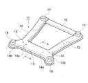
サブフレーム11は、図2,4に示すように前後方向に延在した左右一対のサイドフレーム12と、該サブフレーム11の後側部で左右のサイドフレーム12に車幅方向に連設したリヤフレーム13と、サイドフレーム12の後端部に設けた2股部14と、を備えている。
【0019】
2股部14は、サイドフレーム12の後端部で、リヤフレーム13側に向けて延びる内側ブランチ部14aと、サイドフレーム12よりも車幅方向外側に張り出す外側ブランチ部14bとに分岐して構成してある。
【0020】
本実施形態ではこの外側ブランチ部14bを、平面視して前記内側ブランチ部14aよりも後ろ斜め方向に突出して形成してある。
【0021】
また、本実施形態では前記左右のサイドフレーム12とリヤフレーム13とを一体に形成してあり、従って、前記2股部14の内側ブランチ部14aは、リヤフレーム13のサイドフレーム12との連設基部周りを指す。
【0022】
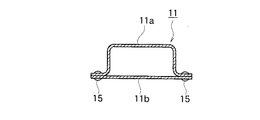
サイドフレーム12とリヤフレーム13とは、逆ハット形断面に形成したアッパパネル11aと、平板状のロアパネル11bとを重合して溶接又はリベット止め等によって閉断面に形成してあり、図3に示す例ではこれらアッパパネル11aとロアパネル11bとを、重合部分でリベット15によって結合固定している。
【0023】
また、本実施形態のサブフレーム12は左右のサイドフレーム12の前端部を車幅方向に結合する、別体成形したフロントフレーム16を備えている。
【0024】
前記サイドフレーム12の前端、および2股部14の外側ブランチ部14bの突出端部には、前側マウント部17および後側マウント部18を形成してある。
【0025】
前記サイドフレーム12、リヤフレーム13、およびフロントフレーム16は何れも平面視して略直線状に形成してある。
【0026】
これら各フレーム12,13,16および2股部14とから構成したサブフレーム11は、前記前側マウント部17を介してサイドメンバ1の前端部に下向きに突設した座部19の下面にボルト・ナット等の締結部材により結合する一方、後側マウント部17を介して前記フロア骨格メンバ8の下面に同様に結合して、これらサイドメンバ1とフロア骨格メンバ8とに跨って結合配置してある。
【0027】
これにより一方のサイドフレーム、例えば右側サイドフレーム12Rの前端部から軸方向に作用する衝突荷重Fを、内側ブランチ部14aからリヤフレーム13を介して他方の左側サイドフレーム12L側に荷重伝達する第1経路Aと、外側ブランチ部14bを介してフロア骨格メンバ8に荷重伝達する第2経路Bと、の2つの荷重伝達経路を構成している。
【0028】
本実施形態では図4に示すように、前記後側マウント部18をエクステンションサイドメンバ2の前端部付近に結合してある。
【0029】
また、前述のパワーユニット10は左右のサイドフレーム12,12に跨って搭載支持してある。
【0030】
以上の第1実施形態の構造によれば、図4に示すように車両前端の右側が障害物Mにオフセット衝突すると、サブフレーム11の右側サイドフレーム12Rの前端側から軸方向に衝突入力Fが集中して作用する。
【0031】
この衝突入力Fは、右側サイドフレーム12Rの後端部の2股部14で、右側サイドフレーム12Rに対して車幅方向内側に指向した第1経路Aに沿って内側ブランチ部14aとリヤフレーム13とを介して左側サイドフレーム12Lに伝達される荷重成分Faと、右側サイドフレーム12Rに対して車幅方向外側に指向した第2経路Bに沿って外側ブランチ部14bを介してフロア骨格メンバ8に伝達される荷重成分Fbとに分散される。
【0032】
前記第2経路Bにおける後側マウント部18の結合部では、サブフレーム11の前後方向剛性が存在するかぎり前後方向の荷重成分Fcは残るが、前述のように2股部14で車幅方向の荷重成分Fa、Fbが生じることで、この前後方向の荷重成分Fcは前端入力荷重Fに較べて小さくすることが可能になる。
【0033】
この結果、サブフレーム11の後退荷重は直ちにキャビンCのフロア5の前部を圧迫することはなく、車幅方向へ広がるような荷重に置き換わってキャビンCのフロア骨格メンバ8に効率的に分散吸収され、キャビンCの変形を抑制することができる。
【0034】
ここで、前述の荷重方向の変換作用としては図5の(A),(B)に示す2つのパターンが考えられる。
【0035】
図5の(A)は2股部14が変形するパターンであり、右側サイドフレーム12Rから伝達された前後方向荷重によって、内側ブランチ部14aと外側ブランチ部14bとが成す角度θが広がる方向に変形することにより、リヤフレーム13は反対側の左側サイドフレーム12Lの2股部14の方向へ圧縮され、外側ブランチ部14bは後側マウント部18を車両後方かつ車幅方向外側へ押し出すように作用する。
【0036】
図5の(B)は右側サイドフレーム12Rと内側ブランチ部14aおよびこれに連なるリヤフレーム13とが変形するパターンである。右側サイドフレーム12Rの前端に入力した衝突荷重により右側のサイドフレーム12Rと内側ブランチ部14aおよびリヤフレーム13とが変形する。外側ブランチ部14bの長さは右側サイドフレーム12Rおよびリヤフレーム13に較べて短いので、前記荷重に対して変形しないかもしくはごく僅かな変形しか生じないため、2股部14が同図の矢印aで示す反時計方向に回転する。その結果、リヤフレーム13は反対側の左側サイドフレーム12Lの2股部14の方向へ圧縮されることになり、その反作用として外側ブランチ部14bは後側マウント部18を車両後方かつ車幅方向外側へ押し出すように作用する。
【0037】
このようにして、右側サイドフレーム12Rの2股部14によって、外側ブランチ部14bの後側マウント部18を車両後方かつ車幅方向外側へ押し出すように作用する変換荷重は、フロア側部の最も剛性の高いエクステンションサイドメンバ2とアウトリガー7とサイドシル6との集合部分で受け止められ、これら各骨格メンバ2,7,6に分散吸収される。
【0038】
一方、前記リヤフレーム13は平面視して略直線状に形成してあるため、衝突側のサイドフレーム12Rの2股部14から車幅方向内側に指向して分散される荷重成分Faを反対側のサイドフレーム12Lの2股部14側へ効率よく伝達することができる。
【0039】
また、2股部14の外側ブランチ部14bの後側マウント部18を、エクステンションサイドメンバ2の前端部付近に結合してあるため、該後側マウント部18から伝達される荷重を該エクステンションサイドメンバ2およびその周辺のフロアパネルの抵抗で支えて、荷重の分散伝達を良好に行うことができ、しかも、外側ブランチ部14bのサイドフレーム12からの突出量を小さくできて、サブフレーム11の小型、軽量化を図ることができる。
【0040】
更に、本実施形態ではサブフレーム11は左右のサイドフレーム12,12の前端部を車幅方向に結合するフロントフレーム16を備えているため、フレーム剛性が高くパワーユニット10等の車両ユニット部品の搭載支持安定性を高めることができ、また、サイドフレーム12を含めて各フレームを平面視して略直線状に形成してあるため、成形性がよくサイドフレーム11を容易に形成することができる。
【0041】
図6は本発明の第2実施形態を示すもので、本実施形態にあっては前記第1実施形態におけるサブフレーム11のリヤフレーム13を、上方に向けて弯曲して形成してある。
【0042】
この第2実施形態の構造によれば、前記第1実施形態の効果に加えて、一方のサイドフレーム12Rの2股部14から分散されて第1経路Aに指向する荷重成分Faをリヤフレーム13により他方のサイドフレーム12L側へ伝達しつつ、該リヤフレーム13がこの荷重成分Faによって弯曲方向に塑性変形して衝突エネルギーの一部を吸収することができる。
【0043】
また、リヤフレーム13が上方に向けて弯曲しているため、フロントコンパートメントF・C内からフロア5の下側へと延びる排気管や駆動用シャフト等が存在する車両では、これらの部品との干渉を避けたレイアウトが容易となる。
【0044】
図7は本発明の第3実施形態を示すもので、本実施形態にあっては前記第1実施形態におけるサブフレーム11の2股部14の後側で、内側ブランチ部14aと外側ブランチ部14bとの境界部に脆弱部としてのノッチ19を設けてある。
【0045】
この第3実施形態の構造によれば、前記第1実施形態の効果に加えて、2股部14の内側ブランチ部14aと外側ブランチ部14bとの境界部にノッチ19を設けてあるため、サイドフレーム12の前端側から軸方向に伝達される衝突荷重によって、2股部14が前記ノッチ19を起点としてこれら内側ブランチ部14aと外側ブランチ部14bとの境界部が裂けるように変形して、第1経路Aと第2経路Bへの車幅方向の荷重変換を促進することができる。
【0046】
図8は本発明の第4実施形態を示すもので、本実施形態にあっては前記第1実施形態におけるサイドフレーム11の2股部14を、内側ブランチ部14aと外側ブランチ部14bとがサイドフレーム12から平面略Y字状に分岐するように形成してある。
【0047】
この第4実施形態の構造によれば、前記第1実施形態の効果に加えて、2股部14の内側ブランチ部14aと外側ブランチ部14bとが平面略Y字状に分岐しているため、第1経路Aと第2経路Bとの荷重伝達経路に略均等に荷重分散して、荷重伝達効率を高められる。
【0048】
また、前記第3実施形態と同様にサイドフレーム12の軸方向荷重によって、内側ブランチ部14aと外側ブランチ部14bとの境界の切れ込み部分を起点として、これら内側ブランチ部14aと外側ブランチ部14bとの境界部が裂けるように変形して、第1経路Aと第2経路Bへの車幅方向の荷重変換を促進することができる。
【0049】
図9は本発明の第5実施形態を示すもので、本実施形態にあっては前記第1実施形態におけるサブフレーム11のリヤフレーム13に、その車幅方向中央部の前縁部に衝突荷重に対して後方への屈曲変形を促す脆弱部としてのノッチ21を設けてある。
【0050】
この第5実施形態の構造によれば、前記第1実施形態の効果に加えて、一方のサイドフレーム12Rの2股部14から分散されて第1経路Aに指向する荷重成分Faをリヤフレーム13により他方のサイドフレーム12L側へ伝達しつつ、該リヤフレーム13がこの荷重成分Faによって前記ノッチ21を起点に後方へ屈曲変形し、衝突エネルギーの一部を吸収することができる。
【0051】
このとき、リヤフレーム13はノッチ21のある前縁側が圧縮されて後縁側が伸張されるように屈曲変形するため、後側マウント部18を車幅方向外側へ押し出すようになり、フロア骨格メンバ8による反力を前記屈曲変形に効果的に利用することができる。
【0052】
図10は本発明の第6実施形態を示すもので、本実施形態にあっては、前記第1実施形態におけるサブフレーム11のサイドフレーム12を、車幅方向内側に向けて弯曲して形成してある。
【0053】
この第6実施形態の構造によれば、前記第1実施形態の効果に加えて、サイドフレーム12の前端側に入力した衝突荷重を2股部14へ伝達しつつ、サイドフレーム12がその弯曲によって車幅方向内側に向けて曲げ変形し、衝突エネルギーの一部を吸収することができる。
【0054】
このとき、サイドフレーム12の曲げ変形は前記弯曲した内側方向へ進展してパワーユニット10に干渉するため、この干渉から生じる抵抗力によって前記衝突エネルギーの吸収効果を高めることができる。
【0055】
図11は本発明の第7実施形態を示すもので、本実施形態にあっては、前記第6実施形態におけるサブフレーム11の車幅方向内側に向けて弯曲したサイドフレーム12の車幅方向外側の側縁部、望ましくは略最大弯曲部における車幅方向外側の側縁部に、衝突荷重に対して車幅方向内側への屈曲変形を促す脆弱部としてのノッチ22を形成してある。
【0056】
従って、この第7実施形態の構造によれば、前記第6実施形態の効果に加えて、衝突荷重に対してサイドフレーム12をその最大弯曲部のノッチ22を起点に車幅方向内側への屈曲変形を促進し、かつ、屈曲変形によるパワーユニット10との干渉ポイントを特定して衝突エネルギー吸収効果をより一層高めることができる。
【0057】
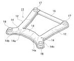
図12,13は本発明の第8実施形態を示すもので、本実施形態にあっては、前記第7実施形態におけるサブフレーム11のリヤフレーム13の前縁部に、前記第5実施例と同様の脆弱部としてのノッチ21を設けてある。
【0058】
図13はオフセット前面衝突した際における本実施形態のサブフレーム12の変形挙動を示している。
【0059】
一方のサイドフレーム12Rの前端側から軸方向に衝突入力Fが集中して作用すると、この衝突荷重を2股部14へ伝達しつつ、サイドフレーム12Rがノッチ22を起点に車幅方向内側に屈曲変形して、前記第7実施形態と同様の効果が得られると共に、2股部14で第1経路Aに分散された荷重成分Faにより、リヤフレーム13がノッチ21を起点に後方に向けて屈曲変形することによって、衝突エネルギー吸収効果を更に高めることができる。
【0060】
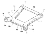
図14は本発明の第9実施形態を示すもので、本実施形態にあっては、前記第1実施形態におけるサブフレーム11のサイドフレーム12の後端部を車幅方向外側へ向けて弯曲して延設し、これら弯曲基部間に跨って別体成形したリヤフレーム13Aを結合して、サイドフレーム12の後方延設部を外側ブランチ部14bとし、リヤフレーム13Aのサイドフレーム12との結合基部を内側ブランチ部14aとして2股部14を形成している。
【0061】
従って、この第9実施形態の構造によれば、前記第1実施形態の効果に加えて、サイドフレーム12とリヤフレーム13とを別体に形成してあるため、車幅の異なる車両間でサイドフレーム12を共有して、リヤフレーム13およびフロントフレーム16の長さで異なる車幅に対応することができる。
【0062】
図15は本発明の第10実施形態を示すもので、本実施形態にあっては、前記第1実施形態におけるサブフレーム11の2股部14Aを、アルミ合金等の軽量金属材料をもって鋳造成形する一方、サイドフレーム12A、リヤフレーム13Bを同様の金属材料をもって押出し成形してそれぞれを別体とし、前記2股部14Aをサイドフレーム12Aの後端部に接続固定すると共に、左右の2股部14A,14Aの内側ブランチ部14a,14a間に、リヤフレーム13Bを接続固定してある。
【0063】
従って、この第10実施形態の構造によれば、前記第1実施形態の効果に加えて、2股部14Aの設計および成形を容易に行えると共に、前記第9実施形態と同様にリヤフレーム13Bおよびフロントフレーム16の長さで異なる車幅に対応することができる。
【0064】
前記第1実施形態ではサブフレーム11の後側マウント部18をエクステンションメンバ2の前端部付近に結合しているが、この他、図16に示す第11実施形態のように、2股部14の外側ブランチ部14bの車幅方向外側への突出量を大きくして、後側マウント部18をサイドシル6の前端部付近に結合することができる。
【0065】
このように、後側マウント部18をサイドシル6の前端部付近に結合することによって、該後側マウント部18からの分散荷重を、フロア骨格メンバ8の中でも最も剛性の高いサイドシル6に直接伝達することができて、分散荷重の吸収効果を高めることができる。
【0066】
また、図17に示す第12実施形態のように、前記後側マウント部18をアウトリガー7に結合することもでき、この場合、後側マウント部18からの分散荷重のサイドシル6への伝達性が向上すると共に、アウトリガー7の塑性変形によって衝突エネルギーの一部を吸収することもできる。
【図面の簡単な説明】
【図1】本発明の構造を採用した自動車の前部を下側から見た斜視図。
【図2】本発明の第1実施形態におけるサブフレームの斜視図。
【図3】図2のA−A線に沿う断面図。
【図4】本発明の第1実施形態を透視的に示す平面説明図。
【図5】本発明の第1実施形態におけるサブフレームの2股部の変形挙動を(A)のパターンと(B)のパターンとについて説明するイメージ図。
【図6】本発明の第2実施形態におけるサブフレームの斜視図。
【図7】本発明の第3実施形態におけるサブフレームの斜視図。
【図8】本発明の第4実施形態におけるサブフレームの斜視図。
【図9】本発明の第5実施形態におけるサブフレームの斜視図。
【図10】本発明の第6実施形態を透視的に示す平面説明図。
【図11】本発明の第7実施形態におけるサブフレームの斜視図。
【図12】本発明の第8実施形態におけるサブフレームの斜視図。
【図13】本発明の第8実施形態の変形挙動を透視的に示す平面説明図。
【図14】本発明の第9実施形態におけるサブフレームの斜視図。
【図15】本発明の第10実施形態におけるサブフレームの斜視図。
【図16】本発明の第11実施形態を透視的に示す平面説明図。
【図17】本発明の第12実施形態を透視的に示す平面説明図。
【符号の説明】
1…サイドメンバ(フロントコンパートメントの骨格メンバ)
2…エクステンションサイドメンバ
3…バンパーレインフォース
5…フロア
6…サイドシル
7…アウトリガー
8…フロア骨格メンバ
10…パワーユニット(車両ユニット部品)
11…サブフレーム
12,12A…サイドフレーム
13,13A,13B…リヤフレーム
14,14A…2股部
14a…内側ブランチ部
14b…外側ブランチ部
16…フロントフレーム
17…前側マウント部
18…後側マウント部
19,21,22…ノッチ(脆弱部)
F・C…フロントコンパートメント
C…キャビン
A…荷重伝達の第1経路
B…荷重伝達の第2経路
F…衝突荷重[0001]
BACKGROUND OF THE INVENTION
The present invention relates to a vehicle body front structure.
[0002]
[Prior art]
Generally, the front body structure of an automobile is designed such that when a vehicle collides with the front, a side member, which is a longitudinal skeleton member of the front compartment, is crushed and deformed in the axial direction to absorb collision energy.
[0003]
However, the side member may be bent and deformed at the time of a collision due to the fact that the shape of the side member is not necessarily straight or that a power unit such as a heavy engine or drive motor is attached.
[0004]
In addition, in the case of an offset frontal collision, the collision input is concentrated on the side member on one side, so that there is a case where the collision energy cannot be sufficiently absorbed. Therefore, conventionally, as disclosed in JP-A-9-119322, the above-mentioned A large sub-frame that suspends vehicle unit parts such as power units and suspension parts is formed separately, and the sub-frame is mounted on the side member from below, so that not only the side member but also the sub-frame is deformed at the time of frontal collision. In order to increase the amount of collision energy absorption, it is known.
[0005]
The sub-frame is formed in a planar rectangle having substantially the same width as the space between the left and right side members between the left and right side frames and the front and rear cross members before and after connecting the left and right side frames. Mount portions are provided at the four corners, and are coupled to the lower surfaces of the left and right side members via the mount portions.
[0006]
[Problems to be solved by the invention]
Since the front and rear mount parts of the subframe are set on the extension of the straight side frame in plan view, when a collision input acts in the axial direction from the front end side of the side frame during a frontal collision, A load tends to act on the joint portion of the mount portion in the direction of the collision input line in the axial direction of the side frame.
[0007]
In order to prevent the coupling portion of the rear mount portion from moving backward due to the collision input and to suppress the deformation of the cabin, it is combined with reinforcing the periphery of the coupling portion of the rear mount portion to increase the rigidity. Therefore, it is necessary to increase the rigidity of the front part of the cabin, and there is no denying that it is disadvantageous in terms of weight and cost.
[0008]
Therefore, the present invention can efficiently disperse and transmit the collision input at the time of a frontal collision to the floor skeleton member of the cabin at the rear end side of the subframe, and protect the cabin without taking a sufficient reinforcement structure with a small weight increase. A vehicle body front structure that can be provided is provided.
[0009]
[Means for Solving the Problems]
In the present invention, the subframe on which the vehicle unit parts are mounted and supported is coupled and disposed across the skeletal member of the front compartment and the floor skeletal member of the cabin at the lower side of the front compartment, The sub-frame includes a pair of left and right side frames extending in the front-rear direction, and a rear frame connected to the left and right side frames on the rear side of the sub-frame in the vehicle width direction. On the rear side, a collision load acting in the axial direction from the front end side of one side frame is directed inward in the vehicle width direction with respect to the one side frame, and the other side frame via the rear frame. a first path for load transfer to the side, vehicle rear and vehicle width direction on the floor framework member directed outward in the vehicle width direction relative to the one side frame It is a second path for load transfer to push outward, in that it has configured two load transfer path for converting the load component extending in the vehicle width direction and gist.
[0010]
【The invention's effect】
According to the present invention, when the collision input concentrates on one side frame of the subframe due to the offset frontal collision and the collision input acts in the axial direction from the front end side of one side frame, the collision input is applied to the one side frame. A load component transmitted to the other side frame via the rear frame, directed to the inner side in the vehicle width direction with respect to the one side frame by the first path, and the second path It is distributed to the load component transmitted to the floor skeleton member, directed outward in the vehicle width direction with respect to one side frame.
[0011]
As a result, the reverse load of the subframe does not immediately squeeze the front of the cabin floor, but is replaced with a load that spreads in the vehicle width direction and is efficiently dispersed and absorbed by the cabin floor skeleton members, thereby deforming the cabin. Can be suppressed.
[0012]
DETAILED DESCRIPTION OF THE INVENTION
Hereinafter, embodiments of the present invention will be described in detail with reference to the drawings.
[0013]
In FIG. 1,
[0014]
The pair of left and right side members 1.1 are joined at their front end portions by a
[0015]
[0016]
Therefore, in the present embodiment, the
[0017]
At the lower end of the front compartments F and C, a
[0018]
As shown in FIGS. 2 and 4, the
[0019]
The bifurcated
[0020]
In the present embodiment, the
[0021]
In the present embodiment, the left and
[0022]
The
[0023]
Further, the
[0024]
A
[0025]
The
[0026]
The
[0027]
As a result, the collision load F acting in the axial direction from the front end portion of one side frame, for example, the
[0028]
In this embodiment, as shown in FIG. 4, the
[0029]
The
[0030]
According to the structure of the first embodiment described above, when the right side of the front end of the vehicle has an offset collision with the obstacle M as shown in FIG. 4, the collision input F is axially applied from the front end side of the
[0031]
The collision input F is a
[0032]
In the joint portion of the
[0033]
As a result, the backward load of the
[0034]
Here, in FIG. 5 is a conversion function of the load Direction of the aforementioned (A), can be considered two patterns shown in (B).
[0035]
FIG. 5A shows a pattern in which the
[0036]
FIG. 5B shows a pattern in which the
[0037]
In this way, the conversion load that acts to push the
[0038]
On the other hand, since the
[0039]
Further, since the
[0040]
Further, in the present embodiment, the
[0041]
FIG. 6 shows a second embodiment of the present invention. In this embodiment, the
[0042]
According to the structure of the second embodiment, in addition to the effect of the first embodiment, the load component Fa distributed from the two
[0043]
Further, since the
[0044]
FIG. 7 shows a third embodiment of the present invention. In this embodiment, an
[0045]
According to the structure of the third embodiment, in addition to the effects of the first embodiment, the
[0046]
FIG. 8 shows a fourth embodiment of the present invention. In the present embodiment, the
[0047]
According to the structure of the fourth embodiment, in addition to the effects of the first embodiment, the
[0048]
Further, as in the third embodiment, due to the axial load of the
[0049]
FIG. 9 shows a fifth embodiment of the present invention. In this embodiment, a collision load is applied to the
[0050]
According to the structure of the fifth embodiment, in addition to the effects of the first embodiment, the load component Fa distributed from the two
[0051]
At this time, the
[0052]
FIG. 10 shows a sixth embodiment of the present invention. In this embodiment, the
[0053]
According to the structure of the sixth embodiment, in addition to the effects of the first embodiment, the
[0054]
At this time, the bending deformation of the
[0055]
FIG. 11 shows a seventh embodiment of the present invention. In this embodiment, the outer side of the
[0056]
Therefore, according to the structure of the seventh embodiment, in addition to the effects of the sixth embodiment, the
[0057]
FIGS. 12 and 13 show an eighth embodiment of the present invention. In this embodiment, the front edge portion of the
[0058]
FIG. 13 shows the deformation behavior of the
[0059]
When the collision input F concentrates and acts in the axial direction from the front end side of one
[0060]
FIG. 14 shows a ninth embodiment of the present invention. In this embodiment, the rear end portion of the
[0061]
Therefore, according to the structure of the ninth embodiment, in addition to the effects of the first embodiment, the
[0062]
FIG. 15 shows a tenth embodiment of the present invention. In this embodiment, the forked
[0063]
Therefore, according to the structure of the tenth embodiment, in addition to the effects of the first embodiment, the
[0064]
In the first embodiment, the
[0065]
In this way, by connecting the
[0066]
Further, as in the twelfth embodiment shown in FIG. 17, the
[Brief description of the drawings]
FIG. 1 is a perspective view of a front portion of an automobile adopting the structure of the present invention as viewed from below.
FIG. 2 is a perspective view of a subframe in the first embodiment of the present invention.
3 is a cross-sectional view taken along line AA in FIG.
FIG. 4 is an explanatory plan view transparently showing the first embodiment of the present invention.
FIGS. 5A and 5B are image diagrams for explaining the deformation behavior of the bifurcated portion of the subframe in the first embodiment of the present invention with respect to the pattern (A) and the pattern (B).
FIG. 6 is a perspective view of a subframe according to a second embodiment of the present invention.
FIG. 7 is a perspective view of a subframe according to a third embodiment of the present invention.
FIG. 8 is a perspective view of a subframe according to a fourth embodiment of the present invention.
FIG. 9 is a perspective view of a subframe according to a fifth embodiment of the present invention.
FIG. 10 is an explanatory plan view transparently showing a sixth embodiment of the present invention.
FIG. 11 is a perspective view of a subframe in a seventh embodiment of the present invention.
FIG. 12 is a perspective view of a subframe according to an eighth embodiment of the present invention.
FIG. 13 is an explanatory plan view transparently showing the deformation behavior of the eighth embodiment of the present invention.
FIG. 14 is a perspective view of a subframe in a ninth embodiment of the present invention.
FIG. 15 is a perspective view of a subframe according to a tenth embodiment of the present invention.
FIG. 16 is an explanatory plan view showing the eleventh embodiment of the present invention in a perspective manner;
FIG. 17 is an explanatory plan view showing a twelfth embodiment of the present invention in a perspective manner;
[Explanation of symbols]
1 ... Side member (skeleton member of front compartment)
2 ...
DESCRIPTION OF
F · C ... Front compartment C ... Cabin A ... First path B of load transmission ... Second path of load transmission F ... Collision load
Claims (17)
前記サブフレームは、前後方向に延在した左右一対のサイドフレームと、該サブフレームの後側で前記左右のサイドフレームに車幅方向に連設したリヤフレームと、を備えていて、
該サブフレームの後側部に、一方のサイドフレームの前端側から軸方向に作用する衝突荷重を、前記一方のサイドフレームに対して車幅方向内側に指向して前記リヤフレームを介して他方のサイドフレーム側に荷重伝達する第1経路と、前記一方のサイドフレームに対して車幅方向外側に指向して前記フロア骨格メンバに車両後方かつ車幅方向外側へ押し出すように荷重伝達する第2経路と、で車幅方向に広がる荷重成分に変換する2つの荷重伝達経路を構成したことを特徴とする車体前部構造。In the lower part of the front compartment, a subframe is coupled and arranged across the skeleton member of the front compartment and the floor skeleton member of the cabin, and vehicle unit parts are mounted and supported on the subframe,
The sub-frame includes a pair of left and right side frames extending in the front-rear direction, and a rear frame connected to the left and right side frames in the vehicle width direction on the rear side of the sub-frame,
A collision load acting in the axial direction from the front end side of one side frame is directed to the inner side in the vehicle width direction with respect to the one side frame on the rear side portion of the sub frame and the other side through the rear frame. A first path for transmitting a load to the side frame side, and a second path for transmitting the load so as to push the one side frame toward the outside in the vehicle width direction and to push the floor frame member to the rear and the vehicle width direction outside The vehicle body front part structure is characterized in that two load transmission paths for converting into load components spreading in the vehicle width direction are configured.
前記サブフレームは、前後方向に延在した左右一対のサイドフレームと、
該サブフレームの後側部で左右一対のサイドフレームに車幅方向に連設したリヤフレームと、
各サイドフレームの後端部で、リヤフレーム側に向けて延びる内側ブランチ部と、サイドフレームよりも車幅方向外側に張り出す外側ブランチ部と、に分岐した2股部と、を備え、
前記各サイドフレームの前端部を前側マウント部を介してサイドメンバの下面に結合すると共に、前記各2股部の外側ブランチ部を後側マウント部を介してフロア骨格メンバの下面に結合して、前記2股部により、一方のサイドフレームの前端側から軸方向に作用する衝突荷重を、内側ブランチ部からリヤフレームを介して他方のサイドフレーム側に荷重伝達する第1経路と、外側ブランチ部を介してフロア骨格メンバに車両後方かつ車幅方向外側へ押し出すように荷重伝達する第2経路と、で車幅方向に広がる荷重成分に変換する2つの荷重伝達経路を構成したことを特徴とする車体前部構造。At the lower part of the front compartment, a subframe is coupled and disposed across the lower surface of a pair of left and right side members constituting the front-rear frame member of the front compartment and the lower surface of the cabin floor frame member. A structure in which vehicle unit parts are mounted and supported,
The sub-frame includes a pair of left and right side frames extending in the front-rear direction;
A rear frame connected in a vehicle width direction to a pair of left and right side frames at the rear side of the sub frame;
At the rear end portion of each side frame, an inner branch portion extending toward the rear frame side, and an outer branch portion projecting outward in the vehicle width direction from the side frame, a bifurcated portion is provided.
The front end portion of each side frame is coupled to the lower surface of the side member via the front mounting portion, and the outer branch portion of each of the two crotch portions is coupled to the lower surface of the floor skeleton member via the rear mounting portion, A first path for transmitting a collision load acting in the axial direction from the front end side of one side frame to the other side frame side from the inner branch portion via the rear frame by the bifurcated portion, and an outer branch portion And a second path that transmits the load to the floor skeleton member so as to push the vehicle rearward and outward in the vehicle width direction, and two load transmission paths that convert the load component to spread in the vehicle width direction. Front structure.
前記キャビンのフロア側部に前後方向に延在配置したサイドシルと、
前記エクステンションサイドメンバの前端部とサイドシルの前端部とを結合したアウトリガーと、で構成したことを特徴とする請求項2に記載の車体前部構造。An extension side member extending around the floor frame member from the rear end of the side member to the lower floor of the cabin and extending in the front-rear direction;
A side sill extending in the front-rear direction on the floor side of the cabin;
The vehicle body front part structure according to claim 2, comprising an outrigger in which a front end part of the extension side member and a front end part of a side sill are combined.
Priority Applications (5)
| Application Number | Priority Date | Filing Date | Title |
|---|---|---|---|
| JP2001330734A JP3606250B2 (en) | 2001-10-29 | 2001-10-29 | Body front structure |
| EP06008024A EP1676769A3 (en) | 2001-10-29 | 2002-09-09 | Front body structure for vehicle |
| EP02020172A EP1306289B1 (en) | 2001-10-29 | 2002-09-09 | Front body structure for vehicle |
| DE60216034T DE60216034T2 (en) | 2001-10-29 | 2002-09-09 | Front end structure of a motor vehicle |
| US10/274,918 US6843524B2 (en) | 2001-10-29 | 2002-10-22 | Front body structure for vehicle |
Applications Claiming Priority (1)
| Application Number | Priority Date | Filing Date | Title |
|---|---|---|---|
| JP2001330734A JP3606250B2 (en) | 2001-10-29 | 2001-10-29 | Body front structure |
Publications (2)
| Publication Number | Publication Date |
|---|---|
| JP2003127893A JP2003127893A (en) | 2003-05-08 |
| JP3606250B2 true JP3606250B2 (en) | 2005-01-05 |
Family
ID=19146415
Family Applications (1)
| Application Number | Title | Priority Date | Filing Date |
|---|---|---|---|
| JP2001330734A Expired - Fee Related JP3606250B2 (en) | 2001-10-29 | 2001-10-29 | Body front structure |
Country Status (4)
| Country | Link |
|---|---|
| US (1) | US6843524B2 (en) |
| EP (2) | EP1676769A3 (en) |
| JP (1) | JP3606250B2 (en) |
| DE (1) | DE60216034T2 (en) |
Families Citing this family (64)
| Publication number | Priority date | Publication date | Assignee | Title |
|---|---|---|---|---|
| DE10157837A1 (en) | 2001-11-24 | 2003-06-05 | Opel Adam Ag | Body with frame-like axle support |
| JP2005153578A (en) * | 2003-11-21 | 2005-06-16 | Fuji Heavy Ind Ltd | Suspension support structure |
| US7213873B2 (en) * | 2004-03-25 | 2007-05-08 | Mazda Motor Corporation | Vehicle front-part structure |
| US7108098B2 (en) * | 2004-06-30 | 2006-09-19 | Cnh America Llc | Engine subframe mounting arrangement |
| US20060201227A1 (en) * | 2004-10-01 | 2006-09-14 | Copperweld Canada Inc. | Vehicle structural components made from tubular members and method therefor |
| JP4325530B2 (en) * | 2004-10-14 | 2009-09-02 | 日産自動車株式会社 | Suspension member |
| JP4655654B2 (en) * | 2005-02-04 | 2011-03-23 | 日産自動車株式会社 | Lower body structure |
| JP4550673B2 (en) * | 2005-06-17 | 2010-09-22 | 本田技研工業株式会社 | Vehicle subframe |
| JP4825583B2 (en) * | 2005-06-28 | 2011-11-30 | 本田技研工業株式会社 | Body structure |
| US20070251751A1 (en) * | 2006-05-01 | 2007-11-01 | Textron Inc. | Cast Aluminum Frame Component for Golf Cars and Small Utility Vehicles |
| JP5201864B2 (en) * | 2007-03-30 | 2013-06-05 | 三菱自動車工業株式会社 | Body structure |
| US20100171297A1 (en) * | 2007-09-11 | 2010-07-08 | Bae Systems Plc | Chassis |
| DE602008000209D1 (en) * | 2007-10-10 | 2009-11-26 | Honda Motor Co Ltd | Front part construction of a vehicle body |
| DE102008010551A1 (en) * | 2008-02-22 | 2009-08-27 | Dr. Ing. H.C. F. Porsche Aktiengesellschaft | Subframe for a rear axle of a motor vehicle |
| JP2009220754A (en) * | 2008-03-18 | 2009-10-01 | Toyota Auto Body Co Ltd | Front body structure of vehicle |
| DE102008016924A1 (en) * | 2008-04-02 | 2008-11-20 | Daimler Ag | Front spring hanger for lorry, has side part assigned to respective frame longitudinal supports of vehicle frame, where side part is designed as aluminum-casting components or aluminum alloy-casting components |
| DE102008056501B4 (en) * | 2008-11-08 | 2019-05-16 | Dr. Ing. H.C. F. Porsche Aktiengesellschaft | Automotive body |
| JP4930576B2 (en) * | 2009-02-27 | 2012-05-16 | 日産自動車株式会社 | Motor support structure |
| DE102009041771A1 (en) † | 2009-09-16 | 2011-03-17 | Volkswagen Ag | Subframe for a motor vehicle |
| FR2952017B1 (en) * | 2009-11-05 | 2014-10-24 | Peugeot Citroen Automobiles Sa | FRONT PART OF AUTOMOTIVE VEHICLE BODY |
| JP5329576B2 (en) | 2011-01-26 | 2013-10-30 | 本田技研工業株式会社 | Vehicle body front |
| JP5329575B2 (en) | 2011-01-26 | 2013-10-30 | 本田技研工業株式会社 | Vehicle body front |
| DE102011100325B4 (en) * | 2011-05-04 | 2020-07-30 | Audi Ag | Construction of a vehicle |
| DE102011102116A1 (en) * | 2011-05-20 | 2012-11-22 | GM Global Technology Operations LLC (n. d. Gesetzen des Staates Delaware) | Crash structure for connection to a front auxiliary frame for a motor vehicle |
| US8646790B2 (en) | 2012-04-12 | 2014-02-11 | Toyota Motor Engineering & Manufacturing North America, Inc. | Sub-frame intrusion control by ramping during frontal impact for electric vehicle battery protection |
| US8540259B1 (en) | 2012-04-12 | 2013-09-24 | Toyota Motor Engineering & Manufacturing North America, Inc. | Construction method to control front engine compartment deformation |
| US8646791B2 (en) | 2012-04-12 | 2014-02-11 | Toyota Motor Engineering & Manufacturing North America, Inc. | Electric vehicle construction methods for frontal impact utilizing deformation shape control |
| US8613461B2 (en) | 2012-04-12 | 2013-12-24 | Toyota Motor Engineering & Manufacturing North America, Inc. | Tether approach to control underbody energy absorption interaction with subframe |
| US8646792B2 (en) | 2012-04-12 | 2014-02-11 | Toyota Motor Engineering & Manufacturing North America, Inc. | Subframe intrusion control by steering gear catcher |
| US8585066B2 (en) | 2012-04-12 | 2013-11-19 | Toyota Motor Engineering & Manufacturing North America, Inc. | Electric vehicle construction methods for frontal impact |
| DE102012222809B4 (en) * | 2012-12-11 | 2019-08-29 | Bayerische Motoren Werke Aktiengesellschaft | Front-end structure |
| JP5954203B2 (en) * | 2013-01-29 | 2016-07-20 | マツダ株式会社 | Front body structure of the vehicle |
| DE102013106433B4 (en) | 2013-06-20 | 2024-05-08 | Dr. Ing. H.C. F. Porsche Aktiengesellschaft | Supporting frame for a motor vehicle |
| JP6021769B2 (en) * | 2013-09-13 | 2016-11-09 | 本田技研工業株式会社 | Subframe for vehicle and method for manufacturing the same |
| FR3030428B1 (en) * | 2014-12-18 | 2018-06-15 | Renault S.A.S | CRADLE OF A MOTOR VEHICLE |
| US10112563B2 (en) | 2015-06-30 | 2018-10-30 | Faraday & Future Inc. | Tapered crush can |
| US10300948B2 (en) | 2015-10-30 | 2019-05-28 | Faraday&Future Inc. | Webbing devices for an underbody of a motor vehicle |
| US10131381B2 (en) * | 2015-06-30 | 2018-11-20 | Faraday & Future Inc. | Joint for an underbody of a motor vehicle |
| JP6372619B2 (en) * | 2015-07-08 | 2018-08-15 | 新日鐵住金株式会社 | Bumper reinforcement and vehicle equipped with the same |
| US9944322B2 (en) | 2015-09-08 | 2018-04-17 | Ford Global Technologies, Llc | Composite subframe detachment |
| JP6508031B2 (en) * | 2015-12-18 | 2019-05-08 | トヨタ自動車株式会社 | Vehicle front structure |
| US10239559B2 (en) | 2016-03-14 | 2019-03-26 | Honda Motor Co., Ltd. | Vehicle frames and methods of assembling the same |
| JP6555416B2 (en) * | 2016-05-19 | 2019-08-07 | 日産自動車株式会社 | Body front structure |
| DE102016006848B4 (en) | 2016-06-04 | 2025-07-24 | Audi Ag | Axle carrier for a multi-track vehicle |
| US10676132B2 (en) | 2016-07-06 | 2020-06-09 | Toyota Jidosha Kabushiki Kaisha | Suspension member |
| JP6724762B2 (en) * | 2016-07-06 | 2020-07-15 | トヨタ自動車株式会社 | Suspension member |
| IT201600101007A1 (en) * | 2016-10-07 | 2018-04-07 | P Gevs S R L | ELECTRIC TRACTION MOTOR VEHICLE, AND ITS APPLICATION METHOD |
| JP2018154294A (en) * | 2017-03-21 | 2018-10-04 | 三菱自動車工業株式会社 | Body front structure |
| JP6481704B2 (en) | 2017-03-27 | 2019-03-13 | マツダ株式会社 | Front subframe structure |
| JP6865837B2 (en) * | 2017-08-29 | 2021-04-28 | 本田技研工業株式会社 | Vehicle rear structure |
| EP3569479B1 (en) * | 2018-05-15 | 2024-04-03 | Volvo Car Corporation | Subframe for a vehicle |
| DE102019103939A1 (en) * | 2019-02-15 | 2020-08-20 | Bayerische Motoren Werke Aktiengesellschaft | Pre-mountable rear axle module for a motor vehicle |
| JP7267810B2 (en) * | 2019-03-29 | 2023-05-02 | 株式会社エフテック | vehicle subframe |
| KR102660369B1 (en) * | 2019-04-11 | 2024-04-23 | 현대자동차주식회사 | Front body of vehicle |
| KR102807537B1 (en) * | 2019-12-05 | 2025-05-13 | 현대자동차주식회사 | Body for vehicles |
| FR3104120B1 (en) * | 2019-12-09 | 2023-06-16 | Psa Automobiles Sa | Fixing device on a motor vehicle chassis, of the rear end of stretchers of a motor cradle receiving an electric propulsion motor of the vehicle. |
| CN112498491A (en) * | 2020-11-24 | 2021-03-16 | 浙江零跑科技有限公司 | Automobile chassis collision force transmission mechanism and force transmission method |
| US11279243B1 (en) | 2020-11-30 | 2022-03-22 | Nikola Corporation | High voltage electrical system for battery electric vehicle |
| US11820241B2 (en) | 2020-11-30 | 2023-11-21 | Nikola Corporation | Battery pack assembly |
| US12291112B2 (en) | 2020-11-30 | 2025-05-06 | Nikola Corporation | High voltage battery conditioning for battery electric vehicle |
| MX2023006242A (en) | 2020-11-30 | 2023-06-12 | Nikola Corp | Electric vehicle battery frame assembly. |
| CN113562077B (en) * | 2021-08-25 | 2022-08-30 | 岚图汽车科技有限公司 | Multi-level collision energy-absorbing steel front auxiliary frame structure |
| JP7723358B2 (en) * | 2022-03-23 | 2025-08-14 | 三菱自動車工業株式会社 | Vehicle-mounted equipment mounting structure |
| WO2025041305A1 (en) * | 2023-08-23 | 2025-02-27 | 日産自動車株式会社 | Vehicle structure |
Family Cites Families (38)
| Publication number | Priority date | Publication date | Assignee | Title |
|---|---|---|---|---|
| US3252211A (en) * | 1964-01-31 | 1966-05-24 | Lindstrom Rodney | Frame horn replacement method and apparatus |
| US3520552A (en) * | 1968-02-21 | 1970-07-14 | Ford Motor Co | Frame structure for a motor vehicle |
| US4046415A (en) * | 1976-04-08 | 1977-09-06 | General Motors Corporation | Body mount system for a motor vehicle |
| US4263980A (en) * | 1979-05-30 | 1981-04-28 | General Motors Corporation | Powertrain cradle for front-wheel-drive vehicle |
| JPS61181779A (en) * | 1985-02-06 | 1986-08-14 | Mazda Motor Corp | Subframe of automobile |
| DE3603706A1 (en) * | 1986-02-06 | 1987-08-13 | Audi Ag | FRAME ARRANGEMENT OF A PREFERRED CAR WITH A SELF-SUPPORTING CAR BOX |
| JPH0735121B2 (en) * | 1987-04-14 | 1995-04-19 | マツダ株式会社 | Subframe structure of automobile |
| JPH01116777A (en) | 1987-10-30 | 1989-05-09 | Alps Electric Co Ltd | Final display deciding circuit |
| JPH0298074A (en) | 1988-10-04 | 1990-04-10 | Hirose Electric Co Ltd | Electric connector |
| JP2657319B2 (en) * | 1989-08-08 | 1997-09-24 | 本田技研工業株式会社 | Automobile power unit support device |
| JPH0378774A (en) | 1989-08-23 | 1991-04-03 | Ricoh Co Ltd | Electrophotographic copying device |
| JP2771276B2 (en) | 1989-09-01 | 1998-07-02 | 日本電気株式会社 | Semiconductor optical integrated device and manufacturing method thereof |
| US5372216A (en) * | 1990-10-08 | 1994-12-13 | Mazda Motor Corporation | Power plant supporting structure of automotive vehicle |
| DE4129538C2 (en) * | 1991-09-05 | 1993-11-18 | Porsche Ag | Subframe for a motor vehicle |
| US5560651A (en) * | 1993-03-26 | 1996-10-01 | Honda Giken Kogyo Kabushiki Kaisha | Subframe and subframe assembly |
| JP3432578B2 (en) * | 1994-03-09 | 2003-08-04 | 本田技研工業株式会社 | Car subframe |
| SE502654C2 (en) * | 1994-04-12 | 1995-12-04 | Saab Automobile | Arrangements for absorbing collision energy in vehicles |
| DE19529334C2 (en) * | 1994-08-18 | 1997-06-26 | Honda Motor Co Ltd | Subframe for a motor vehicle |
| JP2721312B2 (en) * | 1994-09-29 | 1998-03-04 | 本田技研工業株式会社 | Subframe structure |
| JP2721311B2 (en) * | 1994-09-29 | 1998-03-04 | 本田技研工業株式会社 | Subframe structure for vehicles |
| JP2941668B2 (en) * | 1994-10-05 | 1999-08-25 | 本田技研工業株式会社 | Suspension device mounting structure |
| JP3188946B2 (en) | 1994-12-02 | 2001-07-16 | ダイハツ工業株式会社 | Car steering gear support structure |
| US5862877A (en) * | 1994-12-20 | 1999-01-26 | Cosma International Inc. | Cradle assembly |
| JPH09119322A (en) | 1995-10-27 | 1997-05-06 | Ishikawajima Harima Heavy Ind Co Ltd | Aircraft engine cooling liner |
| US5879026A (en) * | 1995-12-19 | 1999-03-09 | Chrysler Corporation | Vehicle suspension and steering cradle |
| JP3351233B2 (en) | 1995-12-27 | 2002-11-25 | トヨタ自動車株式会社 | Powertrain support device |
| JPH1115559A (en) * | 1997-06-19 | 1999-01-22 | Ricoh Co Ltd | Open / close detection switch and personal computer equipped with the switch |
| US6428046B1 (en) * | 1997-10-17 | 2002-08-06 | The Budd Company | Front cradle for a vehicle |
| JPH11222152A (en) | 1998-02-05 | 1999-08-17 | Kobe Steel Ltd | Manufacture of automobile suspension member |
| JP2000016327A (en) * | 1998-07-01 | 2000-01-18 | Toyota Motor Corp | Front structure of car body |
| DE19858303B4 (en) * | 1998-12-17 | 2005-11-10 | Daimlerchrysler Ag | Front structure for a self-supporting bodyshell of a passenger car |
| JP3690713B2 (en) * | 1999-02-22 | 2005-08-31 | 本田技研工業株式会社 | Subframe mounting structure |
| DE19909945C1 (en) * | 1999-03-06 | 2000-10-26 | Porsche Ag | Subframe for a motor vehicle |
| JP4288632B2 (en) * | 1999-06-03 | 2009-07-01 | マツダ株式会社 | Front body structure of the vehicle |
| US6170875B1 (en) * | 1999-07-01 | 2001-01-09 | Robert Allen Jones | Wheel suspension attachment assembly |
| DE19959607A1 (en) * | 1999-12-10 | 2001-06-13 | Volkswagen Ag | Vehicle body with a strut arrangement on the bottom |
| JP4558137B2 (en) * | 2000-04-28 | 2010-10-06 | 富士重工業株式会社 | Vehicle front structure |
| JP2002053076A (en) * | 2000-08-11 | 2002-02-19 | Toyota Auto Body Co Ltd | Front side member structure of vehicle |
-
2001
- 2001-10-29 JP JP2001330734A patent/JP3606250B2/en not_active Expired - Fee Related
-
2002
- 2002-09-09 EP EP06008024A patent/EP1676769A3/en not_active Withdrawn
- 2002-09-09 DE DE60216034T patent/DE60216034T2/en not_active Expired - Fee Related
- 2002-09-09 EP EP02020172A patent/EP1306289B1/en not_active Expired - Lifetime
- 2002-10-22 US US10/274,918 patent/US6843524B2/en not_active Expired - Fee Related
Also Published As
| Publication number | Publication date |
|---|---|
| DE60216034D1 (en) | 2006-12-28 |
| DE60216034T2 (en) | 2007-03-01 |
| US6843524B2 (en) | 2005-01-18 |
| EP1676769A2 (en) | 2006-07-05 |
| JP2003127893A (en) | 2003-05-08 |
| US20030080587A1 (en) | 2003-05-01 |
| EP1676769A3 (en) | 2006-07-12 |
| EP1306289A1 (en) | 2003-05-02 |
| EP1306289B1 (en) | 2006-11-15 |
Similar Documents
| Publication | Publication Date | Title |
|---|---|---|
| JP3606250B2 (en) | Body front structure | |
| EP2076421B1 (en) | Vehicle front structure | |
| JP4010169B2 (en) | Body structure | |
| JP6020944B2 (en) | Auto body structure | |
| US7104596B2 (en) | Vehicle body structure | |
| JP3976198B2 (en) | Body front structure | |
| JP5201864B2 (en) | Body structure | |
| JP2019137351A (en) | Vehicle body structure | |
| US20040195862A1 (en) | Front body structure for vehicle | |
| JP3659218B2 (en) | Body front structure | |
| US20100187864A1 (en) | Vehicle structure | |
| JP2019006311A (en) | Vehicle-body front part structure | |
| JP2006232147A (en) | Body front structure | |
| JP2004106808A (en) | Body front structure | |
| JP3976199B2 (en) | Body structure | |
| JP2001030954A (en) | Car body front structure | |
| JP3861617B2 (en) | Auto body front structure | |
| JP3606255B2 (en) | Body front structure | |
| JP3591508B2 (en) | Body front structure | |
| JP3889741B2 (en) | Body structure | |
| US12134422B2 (en) | Vehicle front body structure | |
| JP2002331965A (en) | Car body front structure | |
| JP6384562B2 (en) | Vehicle front structure | |
| JP2024088828A (en) | Front body structure | |
| JP5948309B2 (en) | Body structure |
Legal Events
| Date | Code | Title | Description |
|---|---|---|---|
| A977 | Report on retrieval |
Free format text: JAPANESE INTERMEDIATE CODE: A971007 Effective date: 20040528 |
|
| A131 | Notification of reasons for refusal |
Free format text: JAPANESE INTERMEDIATE CODE: A131 Effective date: 20040615 |
|
| A521 | Request for written amendment filed |
Free format text: JAPANESE INTERMEDIATE CODE: A523 Effective date: 20040720 |
|
| TRDD | Decision of grant or rejection written | ||
| A01 | Written decision to grant a patent or to grant a registration (utility model) |
Free format text: JAPANESE INTERMEDIATE CODE: A01 Effective date: 20040914 |
|
| A61 | First payment of annual fees (during grant procedure) |
Free format text: JAPANESE INTERMEDIATE CODE: A61 Effective date: 20040927 |
|
| R150 | Certificate of patent or registration of utility model |
Free format text: JAPANESE INTERMEDIATE CODE: R150 |
|
| LAPS | Cancellation because of no payment of annual fees |