EP2402181A1 - Suspension stop comprising two seal elements - Google Patents
Suspension stop comprising two seal elements Download PDFInfo
- Publication number
- EP2402181A1 EP2402181A1 EP11171092A EP11171092A EP2402181A1 EP 2402181 A1 EP2402181 A1 EP 2402181A1 EP 11171092 A EP11171092 A EP 11171092A EP 11171092 A EP11171092 A EP 11171092A EP 2402181 A1 EP2402181 A1 EP 2402181A1
- Authority
- EP
- European Patent Office
- Prior art keywords
- axial
- suspension
- wall
- suspension stop
- rings
- Prior art date
- Legal status (The legal status is an assumption and is not a legal conclusion. Google has not performed a legal analysis and makes no representation as to the accuracy of the status listed.)
- Granted
Links
Images
Classifications
-
- B—PERFORMING OPERATIONS; TRANSPORTING
- B60—VEHICLES IN GENERAL
- B60G—VEHICLE SUSPENSION ARRANGEMENTS
- B60G15/00—Resilient suspensions characterised by arrangement, location or type of combined spring and vibration damper, e.g. telescopic type
- B60G15/02—Resilient suspensions characterised by arrangement, location or type of combined spring and vibration damper, e.g. telescopic type having mechanical spring
- B60G15/06—Resilient suspensions characterised by arrangement, location or type of combined spring and vibration damper, e.g. telescopic type having mechanical spring and fluid damper
- B60G15/067—Resilient suspensions characterised by arrangement, location or type of combined spring and vibration damper, e.g. telescopic type having mechanical spring and fluid damper characterised by the mounting on the vehicle body or chassis of the spring and damper unit
- B60G15/068—Resilient suspensions characterised by arrangement, location or type of combined spring and vibration damper, e.g. telescopic type having mechanical spring and fluid damper characterised by the mounting on the vehicle body or chassis of the spring and damper unit specially adapted for MacPherson strut-type suspension
-
- B—PERFORMING OPERATIONS; TRANSPORTING
- B60—VEHICLES IN GENERAL
- B60G—VEHICLE SUSPENSION ARRANGEMENTS
- B60G15/00—Resilient suspensions characterised by arrangement, location or type of combined spring and vibration damper, e.g. telescopic type
- B60G15/02—Resilient suspensions characterised by arrangement, location or type of combined spring and vibration damper, e.g. telescopic type having mechanical spring
- B60G15/06—Resilient suspensions characterised by arrangement, location or type of combined spring and vibration damper, e.g. telescopic type having mechanical spring and fluid damper
-
- B—PERFORMING OPERATIONS; TRANSPORTING
- B60—VEHICLES IN GENERAL
- B60G—VEHICLE SUSPENSION ARRANGEMENTS
- B60G13/00—Resilient suspensions characterised by arrangement, location or type of vibration dampers
-
- B—PERFORMING OPERATIONS; TRANSPORTING
- B60—VEHICLES IN GENERAL
- B60G—VEHICLE SUSPENSION ARRANGEMENTS
- B60G15/00—Resilient suspensions characterised by arrangement, location or type of combined spring and vibration damper, e.g. telescopic type
-
- B—PERFORMING OPERATIONS; TRANSPORTING
- B60—VEHICLES IN GENERAL
- B60G—VEHICLE SUSPENSION ARRANGEMENTS
- B60G21/00—Interconnection systems for two or more resiliently-suspended wheels, e.g. for stabilising a vehicle body with respect to acceleration, deceleration or centrifugal forces
- B60G21/02—Interconnection systems for two or more resiliently-suspended wheels, e.g. for stabilising a vehicle body with respect to acceleration, deceleration or centrifugal forces permanently interconnected
- B60G21/04—Interconnection systems for two or more resiliently-suspended wheels, e.g. for stabilising a vehicle body with respect to acceleration, deceleration or centrifugal forces permanently interconnected mechanically
- B60G21/05—Interconnection systems for two or more resiliently-suspended wheels, e.g. for stabilising a vehicle body with respect to acceleration, deceleration or centrifugal forces permanently interconnected mechanically between wheels on the same axle but on different sides of the vehicle, i.e. the left and right wheel suspensions being interconnected
- B60G21/055—Stabiliser bars
-
- B—PERFORMING OPERATIONS; TRANSPORTING
- B60—VEHICLES IN GENERAL
- B60G—VEHICLE SUSPENSION ARRANGEMENTS
- B60G3/00—Resilient suspensions for a single wheel
- B60G3/18—Resilient suspensions for a single wheel with two or more pivoted arms, e.g. parallelogram
- B60G3/20—Resilient suspensions for a single wheel with two or more pivoted arms, e.g. parallelogram all arms being rigid
-
- B—PERFORMING OPERATIONS; TRANSPORTING
- B60—VEHICLES IN GENERAL
- B60G—VEHICLE SUSPENSION ARRANGEMENTS
- B60G7/00—Pivoted suspension arms; Accessories thereof
- B60G7/02—Attaching arms to sprung part of vehicle
-
- F—MECHANICAL ENGINEERING; LIGHTING; HEATING; WEAPONS; BLASTING
- F16—ENGINEERING ELEMENTS AND UNITS; GENERAL MEASURES FOR PRODUCING AND MAINTAINING EFFECTIVE FUNCTIONING OF MACHINES OR INSTALLATIONS; THERMAL INSULATION IN GENERAL
- F16C—SHAFTS; FLEXIBLE SHAFTS; ELEMENTS OR CRANKSHAFT MECHANISMS; ROTARY BODIES OTHER THAN GEARING ELEMENTS; BEARINGS
- F16C19/00—Bearings with rolling contact, for exclusively rotary movement
- F16C19/02—Bearings with rolling contact, for exclusively rotary movement with bearing balls essentially of the same size in one or more circular rows
- F16C19/10—Bearings with rolling contact, for exclusively rotary movement with bearing balls essentially of the same size in one or more circular rows for axial load mainly
-
- F—MECHANICAL ENGINEERING; LIGHTING; HEATING; WEAPONS; BLASTING
- F16—ENGINEERING ELEMENTS AND UNITS; GENERAL MEASURES FOR PRODUCING AND MAINTAINING EFFECTIVE FUNCTIONING OF MACHINES OR INSTALLATIONS; THERMAL INSULATION IN GENERAL
- F16C—SHAFTS; FLEXIBLE SHAFTS; ELEMENTS OR CRANKSHAFT MECHANISMS; ROTARY BODIES OTHER THAN GEARING ELEMENTS; BEARINGS
- F16C33/00—Parts of bearings; Special methods for making bearings or parts thereof
- F16C33/72—Sealings
- F16C33/76—Sealings of ball or roller bearings
- F16C33/761—Sealings of ball or roller bearings specifically for bearings with purely axial load
-
- F—MECHANICAL ENGINEERING; LIGHTING; HEATING; WEAPONS; BLASTING
- F16—ENGINEERING ELEMENTS AND UNITS; GENERAL MEASURES FOR PRODUCING AND MAINTAINING EFFECTIVE FUNCTIONING OF MACHINES OR INSTALLATIONS; THERMAL INSULATION IN GENERAL
- F16C—SHAFTS; FLEXIBLE SHAFTS; ELEMENTS OR CRANKSHAFT MECHANISMS; ROTARY BODIES OTHER THAN GEARING ELEMENTS; BEARINGS
- F16C33/00—Parts of bearings; Special methods for making bearings or parts thereof
- F16C33/72—Sealings
- F16C33/76—Sealings of ball or roller bearings
- F16C33/78—Sealings of ball or roller bearings with a diaphragm, disc, or ring, with or without resilient members
-
- F—MECHANICAL ENGINEERING; LIGHTING; HEATING; WEAPONS; BLASTING
- F16—ENGINEERING ELEMENTS AND UNITS; GENERAL MEASURES FOR PRODUCING AND MAINTAINING EFFECTIVE FUNCTIONING OF MACHINES OR INSTALLATIONS; THERMAL INSULATION IN GENERAL
- F16C—SHAFTS; FLEXIBLE SHAFTS; ELEMENTS OR CRANKSHAFT MECHANISMS; ROTARY BODIES OTHER THAN GEARING ELEMENTS; BEARINGS
- F16C33/00—Parts of bearings; Special methods for making bearings or parts thereof
- F16C33/72—Sealings
- F16C33/76—Sealings of ball or roller bearings
- F16C33/80—Labyrinth sealings
-
- B—PERFORMING OPERATIONS; TRANSPORTING
- B60—VEHICLES IN GENERAL
- B60G—VEHICLE SUSPENSION ARRANGEMENTS
- B60G2204/00—Indexing codes related to suspensions per se or to auxiliary parts
- B60G2204/40—Auxiliary suspension parts; Adjustment of suspensions
- B60G2204/418—Bearings, e.g. ball or roller bearings
-
- F—MECHANICAL ENGINEERING; LIGHTING; HEATING; WEAPONS; BLASTING
- F16—ENGINEERING ELEMENTS AND UNITS; GENERAL MEASURES FOR PRODUCING AND MAINTAINING EFFECTIVE FUNCTIONING OF MACHINES OR INSTALLATIONS; THERMAL INSULATION IN GENERAL
- F16C—SHAFTS; FLEXIBLE SHAFTS; ELEMENTS OR CRANKSHAFT MECHANISMS; ROTARY BODIES OTHER THAN GEARING ELEMENTS; BEARINGS
- F16C2326/00—Articles relating to transporting
- F16C2326/01—Parts of vehicles in general
- F16C2326/05—Vehicle suspensions, e.g. bearings, pivots or connecting rods used therein
Definitions
- the invention relates to a motor vehicle suspension stop, particularly intended to be integrated into a telescopic strut of a motor vehicle steering wheel.
- the invention applies to a suspension stop comprising a fixed upper cup intended to be associated with the vehicle body, a lower rotating cup having a support for the suspension spring and rolling bodies arranged between said cups to allow their rotation. relative.
- seals comprising a flexible sealing element which is fixed or integrated to one of the cups to be in rubbing contact on the other cup.
- This embodiment has the disadvantage of inducing a friction torque during the relative rotation of the cups, which is detrimental to the use of the stop in the mounting of a steering wheel.
- the document WO-2009/019340 proposes a sealing element disposed in rubbing contact on each of the cups, said sealing element being mounted movably relative to at least one cup. This gives a particularly satisfactory compromise between the sealing function and the induced torque, even in case of deformation of the abutment under the effect of the forces undergone.
- this embodiment provides for the formation of a radial groove in a cup, which complicates the production of said cup, in particular by requiring the use of a movable member during the molding of said cup.
- the movable mounting of the sealing element in the groove constrains the production of said element, in particular by requiring that it be collapsible or deformable.
- the invention aims to improve the prior art by providing in particular a sealed suspension stopper that is simpler to perform and mount, while maintaining an optimal compromise between the sealing function and the induced torque.
- the invention proposes a motor vehicle suspension stop, said stop comprising an upper cup, a lower cup and rolling bodies arranged between said cups to allow their relative rotation, said cups being arranged to form between them at least an annular space which is delimited laterally by two respectively inner and outer axial walls, said stop comprising an assembly of at least two reported sealing rings which are axially stacked in said space with axial clearance, said rings being mounted on the inner wall - respectively outer - and forming a radial clearance with the outer wall - respectively inner - so as to form a sealing baffle in said space.
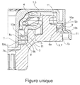
- the positioning terms in space are taken with reference to the axis of rotation of the suspension stop (vertical in the figure which shows one side of the section, the other side being symmetrical with respect to said axis ).
- the term “inside” relates to a disposition close to this axis and the term “outside” relates to a remote layout of this axis.
- the terms “upper” and “lower” are relative to the disposition of the stop as shown in the figure.
- a wheel of a motor vehicle including a steering wheel, is mounted on the chassis via a strut that allows the suspension of the body relative to the ground.
- the strut conventionally comprises a damper, a suspension spring and a suspension stop on which the spring bears.
- a suspension abutment which comprises a fixed upper cup 1 intended to be associated with the vehicle body, a lower rotating cup 2 comprising a support 3 for the spring suspension and rolling bodies (not shown) disposed between said cups to allow their relative rotation about an axis.
- the spring when the spring is biased in compression and relaxation, the winding turns of the latter on themselves is modified, which causes the rotation of the lower cup 2.
- the steering of the wheels also induces a rotation lower cup 2.
- the upper and lower cups 1 each comprise a washer 4, 5, in particular made of stamped sheet metal, which is provided with a respectively lower and upper raceway for the rolling bodies.
- the abutment further comprises two trim parts 6, 7, in particular made by molding a rigid thermoplastic material, for example of the polyamide 6.6 type. These parts are respectively a cover 6 associated on the upper washer 4 to be interposed between the frame and said upper washer, and a support 7 associated under the lower washer 5, said support comprising the spring support 3. These parts 6 , 7 allow in particular a recovery of the forces of the spring and possibly those of the abutment shock.
- the support 7 is surrounded by the cover 6 so as to form two annular spaces respectively inside 8 and 9.
- Each of the annular spaces 8, 9 is delimited laterally by two respectively inner and inner inner walls 8a, 9a and 8b, 9b, the inner and outer walls 8a and 8b of the inner annular space 8 being respectively formed on the lid. 6 and the support 7, the inner 9a and outer 9b walls of the outer annular space 9 being formed on respectively the support 7 and the lid 6.
- the annular spaces 8, 9 have a radial clearance so as to allow the rotation of the support 7 relative to the cover 6 without interference between them.
- the suspension stop comprises an assembly of at least two attached sealing rings 10 which are axially stacked in an annular space 8, 9 with axial play.
- the sealing rings 10 may be made, in particular by molding, of rigid polymeric material such as polyethylene, polypropylene, polyamide 6, 6.6, 11 or 12, polyoxymethylene (POM).
- the two annular spaces 8, 9 are equipped with a set of two sealing rings 10 so as to seal both sides of the suspension stop.
- a single annular space, inside 8 or outside 9, is equipped with a set of sealing rings 10, the other being able to be equipped with a sealing device known in the art. prior.
- the sealing rings 10 are mounted on the inner wall 8a, 9a - respectively outer 8b, 9b - and form a radial clearance with the outer wall 8b, 9b - respectively inner 8a, 9a -, so as to form a baffle sealing in the annular space 8, 9.
- a baffle attached to the abutment makes it possible not to constrain the production of the cover 6 and / or the support 7, in particular by not requiring the use of a movable member for the formation of a radial groove.
- the axial clearance between the sealing rings 10 of an assembly may be between 1.2 and 2.4 mm and the radial overlap between said rings may be between 0.8 and 1.6 mm.
- an assembly may comprise a stack of more than two sealing rings 10, said rings being mounted alternately on the axial walls 8a, 8b; 9a, 9b so as to increase the sinuosity of the baffle formed.
- At least one sealing ring 10 is mounted on the axial wall 8a, 8b; 9a, 9b with possibility of axial displacement.
- the two sealing rings 10 can move axially on their respective mounting wall, in particular under the effect of the deformations of the cover 6 relative to the support 7 which are induced by the mechanical stresses that the suspension stop has to undergo. as part of its use.
- sealing rings 10 limit their wear and avoid the risk that they get stuck during deformations of the stop.
- each ring 10 has a fitting surface 11 on the axial wall 8a, 8b; 9a, 9b, the diameter of said seat being substantially equal to that of said wall so as to allow axial sliding of said seat on said wall.
- the support 7 has two extensions 7a, 7b which extend radially respectively under an annular space 8, 9 so as to maintain the set of sealing rings 10 within said space.
- each extension 7a, 7b is arranged facing the cover 6 with a reduced clearance to limit the access of pollutants in each of the annular spaces 8, 9.
- at least one extension may be formed on the cover 6 to maintain the set of sealing rings 10 and / or to form a reduced clearance with the support 7.
- fitting surfaces 11 have a bevelled geometry in order to reduce the interference of fitting on the axial wall 8a, 8b; 9a, 9b.
- it promotes axial movement and pivoting of the sealing ring 10 relative to its mounting wall 8a, 8b; 9a, 9b.
- the mounting of the abutment shown is achieved by stacking the rings 10 of an assembly on the support 7, the bearing surfaces 11 of the upper rings 10a being fitted on the axial walls 8b, 9a of said support. Then, the cover 6 is mounted on the support 7 ensuring the fitting of the bearing surfaces 11 of the lower rings 10b on the axial walls 8a, 9b of said cover.
- the joints made do not require stretching of the sealing rings 10 so as not to limit the choice of material forming said rings.
- the diameter of the sealing rings 10 of an assembly being very close, it is possible to provide a visual keying means, for example that the rings 10 of an assembly are not of the same color and / or present an inscription according to whether they are higher 10a or lower 10b.
- the sealing rings 10 are rendered differentiable so as to limit the possibility of reversing them when they are mounted on the support 7.
Abstract
Description
L'invention concerne une butée de suspension de véhicule automobile, notamment destinée à être intégrée dans une jambe de suspension télescopique d'une roue directrice de véhicule automobile.The invention relates to a motor vehicle suspension stop, particularly intended to be integrated into a telescopic strut of a motor vehicle steering wheel.
L'invention s'applique à une butée de suspension comprenant une coupelle supérieure fixe destinée à être associée à la caisse du véhicule, une coupelle inférieure tournante comportant un appui pour le ressort de suspension et des corps roulants disposés entre lesdites coupelles pour permettre leur rotation relative.The invention applies to a suspension stop comprising a fixed upper cup intended to be associated with the vehicle body, a lower rotating cup having a support for the suspension spring and rolling bodies arranged between said cups to allow their rotation. relative.
Pour empêcher d'une part les fuites du lubrifiant présent dans l'espace de roulement et, d'autre part la contamination dudit espace avec des polluants extérieurs, on connaît l'utilisation de joints d'étanchéité comprenant un élément d'étanchéité souple qui est fixé ou intégré à l'une des coupelles pour être en contact frottant sur l'autre coupelle.To prevent, on the one hand, the leakage of the lubricant present in the running space and, on the other hand, the contamination of said space with external pollutants, the use of seals comprising a flexible sealing element which is fixed or integrated to one of the cups to be in rubbing contact on the other cup.
Cette réalisation présente notamment l'inconvénient d'induire un couple de frottement lors de la rotation relative des coupelles, ce qui est préjudiciable pour l'utilisation de la butée dans le montage d'une roue directrice.This embodiment has the disadvantage of inducing a friction torque during the relative rotation of the cups, which is detrimental to the use of the stop in the mounting of a steering wheel.
Pour résoudre ce problème, le document
Toutefois, lorsque l'élément d'étanchéité est mobile radialement, cette réalisation prévoit la formation d'une gorge radiale dans une coupelle, ce qui complexifie la réalisation de ladite coupelle notamment en nécessitant l'utilisation d'un organe mobile lors du moulage de ladite coupelle.However, when the sealing element is radially movable, this embodiment provides for the formation of a radial groove in a cup, which complicates the production of said cup, in particular by requiring the use of a movable member during the molding of said cup.
En outre, le montage mobile de l'élément d'étanchéité dans la gorge contraint la réalisation dudit élément, notamment en nécessitant qu'il soit repliable ou déformable.In addition, the movable mounting of the sealing element in the groove constrains the production of said element, in particular by requiring that it be collapsible or deformable.
L'invention vise à perfectionner l'art antérieur en proposant notamment une butée de suspension étanche qui soit plus simple à réaliser et à monter, et ce tout en conservant un compromis optimal entre la fonction étanchéité et le couple induit.The invention aims to improve the prior art by providing in particular a sealed suspension stopper that is simpler to perform and mount, while maintaining an optimal compromise between the sealing function and the induced torque.
A cet effet, l'invention propose une butée de suspension de véhicule automobile, ladite butée comprenant une coupelle supérieure, une coupelle inférieure et des corps roulants disposés entre lesdites coupelles pour permettre leur rotation relative, lesdites coupelles étant agencées pour former entre elles au moins un espace annulaire qui est délimité latéralement par deux parois axiales respectivement intérieure et extérieure, ladite butée comprenant un ensemble d'au moins deux anneaux d'étanchéité rapportés qui sont empilés axialement dans ledit espace en présentant un jeu axial, lesdits anneaux étant montés sur la paroi intérieure - respectivement extérieure - et formant un jeu radial avec la paroi extérieure - respectivement intérieure -, de sorte à former une chicane d'étanchéité dans ledit espace.For this purpose, the invention proposes a motor vehicle suspension stop, said stop comprising an upper cup, a lower cup and rolling bodies arranged between said cups to allow their relative rotation, said cups being arranged to form between them at least an annular space which is delimited laterally by two respectively inner and outer axial walls, said stop comprising an assembly of at least two reported sealing rings which are axially stacked in said space with axial clearance, said rings being mounted on the inner wall - respectively outer - and forming a radial clearance with the outer wall - respectively inner - so as to form a sealing baffle in said space.
D'autres particularités et avantages de l'invention apparaîtront dans la description qui suit, faite en référence à la figure jointe qui représente de façon partielle et en coupe axiale une butée de suspension selon un mode de réalisation de l'invention.Other features and advantages of the invention will appear in the description which follows, made with reference to the attached figure which partially and in axial section shows a suspension stop according to one embodiment of the invention.
Dans cette description, les termes de positionnement dans l'espace sont pris en référence à l'axe de rotation de la butée de suspension (vertical sur la figure qui montre un côté de la coupe, l'autre côté étant symétrique par rapport audit axe). En particulier, le terme « intérieur » est relatif à une disposition proche de cet axe et le terme « extérieur » est relatif à une disposition à distance de cet axe. Par ailleurs, les termes « supérieur » et « inférieur » sont relatifs à la disposition de la butée telle que représentée sur la figure.In this description, the positioning terms in space are taken with reference to the axis of rotation of the suspension stop (vertical in the figure which shows one side of the section, the other side being symmetrical with respect to said axis ). In particular, the term "inside" relates to a disposition close to this axis and the term "outside" relates to a remote layout of this axis. Furthermore, the terms "upper" and "lower" are relative to the disposition of the stop as shown in the figure.
Une roue d'un véhicule automobile, notamment une roue directrice, est montée sur le châssis par l'intermédiaire d'une jambe de force qui permet la suspension de la caisse relativement au sol. A cet effet, la jambe de force comprend classiquement un amortisseur, un ressort de suspension ainsi qu'une butée de suspension sur laquelle le ressort vient en appui.A wheel of a motor vehicle, including a steering wheel, is mounted on the chassis via a strut that allows the suspension of the body relative to the ground. For this purpose, the strut conventionally comprises a damper, a suspension spring and a suspension stop on which the spring bears.
En relation avec la figure, on décrit ci-dessous un mode de réalisation d'une butée de suspension qui comprend une coupelle supérieure fixe 1 destinée à être associée à la caisse du véhicule, une coupelle inférieure tournante 2 comportant un appui 3 pour le ressort de suspension et des corps roulants (non représentés) disposés entre lesdites coupelles pour permettre leur rotation relative autour d'un axe. Ainsi, lorsque le ressort est sollicité en compression et en détente, l'enroulement des spires de ce dernier sur elles-mêmes est modifié, ce qui entraîne la rotation de la coupelle inférieure 2. En outre, le braquage des roues induit également une rotation de la coupelle inférieure 2.In relation to the figure, an embodiment of a suspension abutment is described below which comprises a fixed upper cup 1 intended to be associated with the vehicle body, a lower rotating cup 2 comprising a support 3 for the spring suspension and rolling bodies (not shown) disposed between said cups to allow their relative rotation about an axis. Thus, when the spring is biased in compression and relaxation, the winding turns of the latter on themselves is modified, which causes the rotation of the lower cup 2. In addition, the steering of the wheels also induces a rotation lower cup 2.
Dans le mode de réalisation représenté, les coupelles supérieure 1 et inférieure 2 comprennent chacune une rondelle 4, 5, notamment réalisée en tôle emboutie, qui est pourvue d'une piste de roulement respectivement inférieure et supérieure pour les corps roulants.In the embodiment shown, the upper and lower cups 1 each comprise a
La butée comprend en outre deux pièces d'habillage 6, 7, notamment réalisées par moulage d'un matériau thermoplastique rigide, par exemple de type polyamide 6.6. Ces pièces sont respectivement un couvercle 6 associé sur la rondelle supérieure 4 pour être interposé entre le châssis et ladite rondelle supérieure, et un support 7 associé sous la rondelle inférieure 5, ledit support comprenant l'appui ressort 3. Ces pièces d'habillage 6, 7 permettent notamment une reprise des efforts du ressort et éventuellement de ceux de la butée de choc.The abutment further comprises two trim parts 6, 7, in particular made by molding a rigid thermoplastic material, for example of the polyamide 6.6 type. These parts are respectively a cover 6 associated on the upper washer 4 to be interposed between the frame and said upper washer, and a support 7 associated under the
Dans le mode de réalisation représenté, le support 7 est entouré par le couvercle 6 de sorte à former deux espaces annulaires respectivement intérieur 8 et extérieur 9. Chacun des espaces annulaires 8, 9 est délimité latéralement par deux parois axiales respectivement intérieure 8a, 9a et extérieure 8b, 9b, les parois intérieure 8a et extérieure 8b de l'espace annulaire intérieur 8 étant formées sur respectivement le couvercle 6 et le support 7, les parois intérieure 9a et extérieure 9b de l'espace annulaire extérieur 9 étant formées sur respectivement le support 7 et le couvercle 6. En particulier, les espaces annulaires 8, 9 présentent un jeu radial de sorte à permettre la rotation du support 7 par rapport au couvercle 6 sans interférence entre ceux-ci.In the embodiment shown, the support 7 is surrounded by the cover 6 so as to form two annular spaces respectively inside 8 and 9. Each of the annular spaces 8, 9 is delimited laterally by two respectively inner and inner
La butée de suspension comprend un ensemble d'au moins deux anneaux d'étanchéité 10 rapportés qui sont empilés axialement dans un espace annulaire 8, 9 en présentant un jeu axial. En particulier, les anneaux d'étanchéité 10 peuvent être réalisés, notamment par moulage, en matériau polymérique rigide tel que le polyéthylène, le polypropylène, le polyamide 6, 6.6, 11 ou 12, le polyoxyméthylène (POM).The suspension stop comprises an assembly of at least two attached sealing rings 10 which are axially stacked in an annular space 8, 9 with axial play. In particular, the sealing rings 10 may be made, in particular by molding, of rigid polymeric material such as polyethylene, polypropylene, polyamide 6, 6.6, 11 or 12, polyoxymethylene (POM).
Dans le mode de réalisation représenté, les deux espaces annulaires 8, 9 sont équipés d'un ensemble de deux anneaux d'étanchéité 10 de sorte à étanchéifier les deux côtés de la butée de suspension. Toutefois, on peut prévoir qu'un seul espace annulaire, intérieur 8 ou extérieur 9, soit équipé d'un ensemble d'anneaux d'étanchéité 10, l'autre pouvant être équipé d'un dispositif d'étanchéité connu de l'art antérieur.In the embodiment shown, the two annular spaces 8, 9 are equipped with a set of two sealing rings 10 so as to seal both sides of the suspension stop. However, it can be provided that a single annular space, inside 8 or outside 9, is equipped with a set of sealing rings 10, the other being able to be equipped with a sealing device known in the art. prior.
Les anneaux d'étanchéité 10 sont montés sur la paroi intérieure 8a, 9a - respectivement extérieure 8b, 9b - et forment un jeu radial avec la paroi extérieure 8b, 9b - respectivement intérieure 8a, 9a -, de sorte à former une chicane d'étanchéité dans l'espace annulaire 8, 9. En particulier, une chicane rapportée sur la butée permet de ne pas contraindre la réalisation du couvercle 6 et/ou du support 7, notamment en ne nécessitant pas l'utilisation d'un organe mobile pour la formation d'une gorge radiale.The sealing rings 10 are mounted on the
Dans un exemple de réalisation, le jeu axial entre les anneaux d'étanchéité 10 d'un ensemble peut être compris entre 1,2 et 2,4 mm et le recouvrement radial entre lesdits anneaux peut être compris entre 0,8 et 1,6 mm.In an exemplary embodiment, the axial clearance between the sealing rings 10 of an assembly may be between 1.2 and 2.4 mm and the radial overlap between said rings may be between 0.8 and 1.6 mm.
Dans le mode de réalisation représenté, les anneaux supérieurs 10a sont emmanchés sur le support 7 et les anneaux inférieurs 10b sont emmanchés sur le couvercle 6. En variante non représentée, un ensemble peut comprendre un empilement de plus de deux anneaux d'étanchéité 10, lesdits anneaux étant montés de façon alternée sur les parois axiales 8a, 8b ; 9a, 9b de sorte à augmenter la sinuosité de la chicane formée.In the embodiment shown, the
De façon avantageuse, au moins un anneau d'étanchéité 10 est monté sur la paroi axiale 8a, 8b ; 9a, 9b avec possibilité de déplacement axial. En particulier, les deux anneaux d'étanchéité 10 peuvent se déplacer axialement sur leur paroi de montage respective, notamment sous l'effet des déformations du couvercle 6 relativement au support 7 qui sont induites par les sollicitations mécaniques que la butée de suspension a à subir dans le cadre de son utilisation.Advantageously, at least one sealing ring 10 is mounted on the
Ainsi, il est possible de combiner la fonction d'étanchéité procurée par la chicane à la limitation du couple du fait de la possibilité de déplacement des anneaux d'étanchéité 10 par rapport à au moins une coupelle 1, 2. En outre, les déplacements des anneaux d'étanchéité 10 limitent leur usure et évitent le risque qu'ils se coincent lors des déformations de la butée.Thus, it is possible to combine the sealing function provided by the baffle with the limitation of the torque because of the possibility of displacement of the sealing rings 10 with respect to at least one cup 1, 2. sealing rings 10 limit their wear and avoid the risk that they get stuck during deformations of the stop.
Dans le mode de réalisation représenté, chaque anneau 10 présente une portée d'emmanchement 11 sur la paroi axiale 8a, 8b ; 9a, 9b, le diamètre de ladite portée étant sensiblement égal à celui de ladite paroi de sorte à permettre un glissement axial de ladite portée sur ladite paroi.In the embodiment shown, each ring 10 has a
En outre, le support 7 présente deux extensions 7a, 7b qui s'étendent radialement sous respectivement un espace annulaire 8, 9 de sorte à maintenir l'ensemble d'anneaux d'étanchéité 10 à l'intérieur dudit espace. Outre leur fonction de butée axiale pour les anneaux d'étanchéité 10, chaque extension 7a, 7b est disposée en regard du couvercle 6 avec un jeu réduit pour limiter l'accès des polluants dans chacun des espaces annulaires 8, 9. En variante non représentée, au moins une extension peut être formée sur le couvercle 6 pour maintenir l'ensemble d'anneaux d'étanchéité 10 et/ou pour former un jeu réduit avec le support 7.In addition, the support 7 has two
Par ailleurs, les portées 11 d'emmanchement présentent une géométrie biseautée afin de réduire l'interférence d'emmanchement sur la paroi axiale 8a, 8b ; 9a, 9b. Ainsi, on favorise le déplacement axial et le pivotement de l'anneau d'étanchéité 10 par rapport à sa paroi de montage 8a, 8b ; 9a, 9b.In addition, the
Le montage de la butée représentée est réalisé en empilant les anneaux 10 d'un ensemble sur le support 7, les portées 11 des anneaux supérieurs 10a étant emmanchées sur les parois axiales 8b, 9a dudit support. Ensuite, le couvercle 6 est monté sur le support 7 en assurant l'emmanchement des portées 11 des anneaux inférieurs 10b sur les parois axiales 8a, 9b dudit couvercle. En particulier, les emmanchements réalisés ne nécessitent pas un étirement des anneaux d'étanchéité 10 de sorte à ne pas limiter le choix du matériau formant lesdits anneaux.The mounting of the abutment shown is achieved by stacking the rings 10 of an assembly on the support 7, the
Dans cette réalisation, le diamètre des anneaux d'étanchéité 10 d'un ensemble étant très proche, on peut prévoir un moyen visuel de détrompage, par exemple que les anneaux 10 d'un ensemble ne soient pas de la même couleur et/ou présentent une inscription suivant qu'ils soient supérieur 10a ou inférieur 10b. Ainsi, on rend différentiables les anneaux d'étanchéité 10 de sorte à limiter la possibilité de les intervertir lors de leur montage sur le support 7.In this embodiment, the diameter of the sealing rings 10 of an assembly being very close, it is possible to provide a visual keying means, for example that the rings 10 of an assembly are not of the same color and / or present an inscription according to whether they are higher 10a or lower 10b. Thus, the sealing rings 10 are rendered differentiable so as to limit the possibility of reversing them when they are mounted on the support 7.
Claims (10)
Applications Claiming Priority (1)
| Application Number | Priority Date | Filing Date | Title |
|---|---|---|---|
| FR1002714A FR2961747B1 (en) | 2010-06-29 | 2010-06-29 | AUTOMOTIVE VEHICLE SUSPENSION STOP COMPRISING AN ASSEMBLY OF AT LEAST TWO SEAL RINGS REPORTED |
Publications (2)
| Publication Number | Publication Date |
|---|---|
| EP2402181A1 true EP2402181A1 (en) | 2012-01-04 |
| EP2402181B1 EP2402181B1 (en) | 2013-06-12 |
Family
ID=43498645
Family Applications (1)
| Application Number | Title | Priority Date | Filing Date |
|---|---|---|---|
| EP11171092.7A Not-in-force EP2402181B1 (en) | 2010-06-29 | 2011-06-22 | Suspension stop comprising two seal elements |
Country Status (7)
| Country | Link |
|---|---|
| US (1) | US20110317954A1 (en) |
| EP (1) | EP2402181B1 (en) |
| JP (1) | JP2012013228A (en) |
| KR (1) | KR20120001691A (en) |
| BR (1) | BRPI1102695A2 (en) |
| FR (1) | FR2961747B1 (en) |
| RU (1) | RU2562012C2 (en) |
Families Citing this family (4)
| Publication number | Priority date | Publication date | Assignee | Title |
|---|---|---|---|---|
| CN103003600B (en) * | 2010-04-06 | 2015-09-02 | Skf公司 | There is the axial thrust bearing device of seal ring |
| US9028152B2 (en) * | 2012-12-13 | 2015-05-12 | Scheaffler Technologies AG & Co. KG | Diaphragm seal for strut bearing |
| FR3026678B1 (en) * | 2014-10-02 | 2020-04-17 | Ntn-Snr Roulements | MULTIPURPOSE MONOBLOCK CUP SUSPENSION STOP |
| FR3084016B1 (en) | 2018-07-18 | 2020-09-25 | Ntn Snr Roulements | AUTOMOTIVE VEHICLE SUSPENSION STOP |
Citations (2)
| Publication number | Priority date | Publication date | Assignee | Title |
|---|---|---|---|---|
| US2759778A (en) * | 1954-08-31 | 1956-08-21 | Norma Hoffman Bearings Corp | Sealed bearing |
| WO2009019340A2 (en) | 2007-06-29 | 2009-02-12 | Snr Roulements | Suspension stop comprising a mobile seal element |
Family Cites Families (12)
| Publication number | Priority date | Publication date | Assignee | Title |
|---|---|---|---|---|
| US5467971A (en) * | 1994-08-08 | 1995-11-21 | General Motors Corporation | Strut assembly with integral bearing and spring seat |
| FR2759437B1 (en) * | 1997-02-13 | 1999-05-07 | Skf France | CLUTCH MANEUVER WITH ELASTIC SELF-ALIGNMENT MEMBER |
| DE19716218C2 (en) * | 1997-04-18 | 2001-08-30 | Schaeffler Waelzlager Ohg | Clutch release bearing |
| FR2779096B1 (en) * | 1998-05-28 | 2000-12-15 | Skf France | SUSPENSION STOP DEVICE |
| DE19960699B4 (en) * | 1999-12-16 | 2010-09-30 | Schaeffler Technologies Gmbh & Co. Kg | Strut bearing |
| FR2822508B1 (en) * | 2001-03-21 | 2003-08-22 | Skf Ab | SUSPENSION STOP WITH RETAINING MEANS |
| FR2829429B1 (en) * | 2001-09-12 | 2003-12-12 | Skf Ab | STOP SUSPENSION DEVICE |
| FR2859412B1 (en) * | 2003-09-04 | 2006-02-24 | Skf Ab | STOP SUSPENSION DEVICE |
| FR2872558B1 (en) * | 2004-07-02 | 2006-09-29 | Skf Ab | CLUTCH FASTER AND METHOD OF MANUFACTURE |
| FR2904261B1 (en) * | 2006-07-26 | 2011-05-13 | Roulements Soc Nouvelle | STOPPER OF SUSPENSION AND SUSPENSION LEG WITH SUCH A ROCKET |
| RU62183U1 (en) * | 2006-10-18 | 2007-03-27 | Иосиф Яковлевич Пинус | BEARING-BEARING WITH COMBINED FRICTION COUPLE (OPTIONS) |
| FR2908849B1 (en) * | 2006-11-22 | 2009-02-13 | Snr Roulements Sa | BEARING CAGE WITH AN OBLONGED ALVEOL AND AN OBLIQUE CONTACT BALL BEARING COMPRISING SUCH A CAGE. |
-
2010
- 2010-06-29 FR FR1002714A patent/FR2961747B1/en not_active Expired - Fee Related
-
2011
- 2011-06-22 EP EP11171092.7A patent/EP2402181B1/en not_active Not-in-force
- 2011-06-24 JP JP2011140471A patent/JP2012013228A/en not_active Withdrawn
- 2011-06-28 RU RU2011126294/11A patent/RU2562012C2/en not_active IP Right Cessation
- 2011-06-28 US US13/170,442 patent/US20110317954A1/en not_active Abandoned
- 2011-06-29 BR BRPI1102695-2A patent/BRPI1102695A2/en not_active IP Right Cessation
- 2011-06-29 KR KR1020110063788A patent/KR20120001691A/en not_active Application Discontinuation
Patent Citations (2)
| Publication number | Priority date | Publication date | Assignee | Title |
|---|---|---|---|---|
| US2759778A (en) * | 1954-08-31 | 1956-08-21 | Norma Hoffman Bearings Corp | Sealed bearing |
| WO2009019340A2 (en) | 2007-06-29 | 2009-02-12 | Snr Roulements | Suspension stop comprising a mobile seal element |
Also Published As
| Publication number | Publication date |
|---|---|
| JP2012013228A (en) | 2012-01-19 |
| EP2402181B1 (en) | 2013-06-12 |
| BRPI1102695A2 (en) | 2012-11-20 |
| RU2562012C2 (en) | 2015-09-10 |
| FR2961747A1 (en) | 2011-12-30 |
| RU2011126294A (en) | 2013-01-10 |
| CN102407744A (en) | 2012-04-11 |
| KR20120001691A (en) | 2012-01-04 |
| FR2961747B1 (en) | 2012-08-10 |
| US20110317954A1 (en) | 2011-12-29 |
Similar Documents
| Publication | Publication Date | Title |
|---|---|---|
| EP2164717B1 (en) | Suspension stop comprising a mobile seal element | |
| EP1170157B1 (en) | Axial rolling bearing for a vehicle suspension with restrainning means | |
| FR3075103B1 (en) | SUSPENSION STOP DEVICE AND FORCE LEG EQUIPPED WITH SUCH A DEVICE | |
| FR2948066A1 (en) | SUSPENSION STOP DEVICE AND FORCE LEG. | |
| FR2779096A1 (en) | SUSPENSION STOP DEVICE | |
| EP3027441B1 (en) | Axial rolling bearing for a vehicle suspension | |
| EP2402181B1 (en) | Suspension stop comprising two seal elements | |
| FR2901737A1 (en) | SUSPENSION STOPPER DEVICE AND FORCE LEG | |
| FR2822508A1 (en) | SUSPENSION STOP WITH RETAINING MEANS | |
| FR2857906A1 (en) | Mounting for strut supporting steerable vehicle wheels comprises ball bearing whose lower ring is supported by reinforced plastic plate which fits on spiral spring, lower surface of plate having seating for buffer sleeve | |
| EP1162091B1 (en) | Sealed axial bearing for a vehicle suspension | |
| FR3003803A1 (en) | SUSPENSION ROCKING DEVICE AND SUSPENSION LEG EQUIPPED WITH SUCH A ROCKET | |
| EP3626486A1 (en) | Suspension bump stop for motor vehicle | |
| FR3025457A1 (en) | SUSPENSION STOP OF MOTOR VEHICLE | |
| EP0014645B1 (en) | Telescopic oleopneumatic suspension strut for a vehicle | |
| EP2517805B1 (en) | Method for manufacturing two washers each comprising a raceway | |
| WO2020016347A1 (en) | Bumpstop for a motor vehicle | |
| FR2947216A1 (en) | Hanger support bearing device for use in suspension strut of front wheel of motor vehicle, has lower supporting plate whose supporting surface is tilted with respect to upper mounting surface of upper supporting plate | |
| FR2825324A1 (en) | Mounting for motor vehicle suspension strut has spring collar with piston rod mounted for rotation in slide bearing | |
| FR2986845A1 (en) | SUSPENSION STOP DEVICE AND FORCE LEG EQUIPPED WITH SUCH A DEVICE | |
| FR3025138A1 (en) | SUSPENSION STOP COMPRISING A MOBILE SEALING ELEMENT | |
| FR3034046A1 (en) | STOP SUSPENSION DEVICE | |
| FR2803561A1 (en) | Spring seating for motor vehicle suspensions strut has upper and lower plastics rings fitting between suspension spring and bodywork and with solid lubricant in one surface | |
| EP3599116B1 (en) | Motor vehicle suspension buffer | |
| FR2946570A1 (en) | SUSPENSION STOPPER DEVICE AND FORCE LEG |
Legal Events
| Date | Code | Title | Description |
|---|---|---|---|
| AK | Designated contracting states |
Kind code of ref document: A1 Designated state(s): AL AT BE BG CH CY CZ DE DK EE ES FI FR GB GR HR HU IE IS IT LI LT LU LV MC MK MT NL NO PL PT RO RS SE SI SK SM TR |
|
| AX | Request for extension of the european patent |
Extension state: BA ME |
|
| PUAI | Public reference made under article 153(3) epc to a published international application that has entered the european phase |
Free format text: ORIGINAL CODE: 0009012 |
|
| 17P | Request for examination filed |
Effective date: 20120611 |
|
| GRAP | Despatch of communication of intention to grant a patent |
Free format text: ORIGINAL CODE: EPIDOSNIGR1 |
|
| RIC1 | Information provided on ipc code assigned before grant |
Ipc: B60G 15/06 20060101AFI20121204BHEP Ipc: F16C 33/76 20060101ALI20121204BHEP Ipc: F16C 19/10 20060101ALI20121204BHEP |
|
| GRAS | Grant fee paid |
Free format text: ORIGINAL CODE: EPIDOSNIGR3 |
|
| GRAA | (expected) grant |
Free format text: ORIGINAL CODE: 0009210 |
|
| AK | Designated contracting states |
Kind code of ref document: B1 Designated state(s): AL AT BE BG CH CY CZ DE DK EE ES FI FR GB GR HR HU IE IS IT LI LT LU LV MC MK MT NL NO PL PT RO RS SE SI SK SM TR |
|
| REG | Reference to a national code |
Ref country code: GB Ref legal event code: FG4D Free format text: NOT ENGLISH |
|
| REG | Reference to a national code |
Ref country code: CH Ref legal event code: EP |
|
| REG | Reference to a national code |
Ref country code: AT Ref legal event code: REF Ref document number: 616536 Country of ref document: AT Kind code of ref document: T Effective date: 20130615 |
|
| REG | Reference to a national code |
Ref country code: IE Ref legal event code: FG4D Free format text: LANGUAGE OF EP DOCUMENT: FRENCH |
|
| REG | Reference to a national code |
Ref country code: DE Ref legal event code: R096 Ref document number: 602011001988 Country of ref document: DE Effective date: 20130808 |
|
| PG25 | Lapsed in a contracting state [announced via postgrant information from national office to epo] |
Ref country code: FI Free format text: LAPSE BECAUSE OF FAILURE TO SUBMIT A TRANSLATION OF THE DESCRIPTION OR TO PAY THE FEE WITHIN THE PRESCRIBED TIME-LIMIT Effective date: 20130612 Ref country code: NO Free format text: LAPSE BECAUSE OF FAILURE TO SUBMIT A TRANSLATION OF THE DESCRIPTION OR TO PAY THE FEE WITHIN THE PRESCRIBED TIME-LIMIT Effective date: 20130912 Ref country code: SE Free format text: LAPSE BECAUSE OF FAILURE TO SUBMIT A TRANSLATION OF THE DESCRIPTION OR TO PAY THE FEE WITHIN THE PRESCRIBED TIME-LIMIT Effective date: 20130612 Ref country code: ES Free format text: LAPSE BECAUSE OF FAILURE TO SUBMIT A TRANSLATION OF THE DESCRIPTION OR TO PAY THE FEE WITHIN THE PRESCRIBED TIME-LIMIT Effective date: 20130923 Ref country code: SI Free format text: LAPSE BECAUSE OF FAILURE TO SUBMIT A TRANSLATION OF THE DESCRIPTION OR TO PAY THE FEE WITHIN THE PRESCRIBED TIME-LIMIT Effective date: 20130612 Ref country code: GR Free format text: LAPSE BECAUSE OF FAILURE TO SUBMIT A TRANSLATION OF THE DESCRIPTION OR TO PAY THE FEE WITHIN THE PRESCRIBED TIME-LIMIT Effective date: 20130913 Ref country code: LT Free format text: LAPSE BECAUSE OF FAILURE TO SUBMIT A TRANSLATION OF THE DESCRIPTION OR TO PAY THE FEE WITHIN THE PRESCRIBED TIME-LIMIT Effective date: 20130612 |
|
| REG | Reference to a national code |
Ref country code: AT Ref legal event code: MK05 Ref document number: 616536 Country of ref document: AT Kind code of ref document: T Effective date: 20130612 |
|
| REG | Reference to a national code |
Ref country code: NL Ref legal event code: VDEP Effective date: 20130612 |
|
| REG | Reference to a national code |
Ref country code: LT Ref legal event code: MG4D |
|
| PG25 | Lapsed in a contracting state [announced via postgrant information from national office to epo] |
Ref country code: HR Free format text: LAPSE BECAUSE OF FAILURE TO SUBMIT A TRANSLATION OF THE DESCRIPTION OR TO PAY THE FEE WITHIN THE PRESCRIBED TIME-LIMIT Effective date: 20130612 Ref country code: RS Free format text: LAPSE BECAUSE OF FAILURE TO SUBMIT A TRANSLATION OF THE DESCRIPTION OR TO PAY THE FEE WITHIN THE PRESCRIBED TIME-LIMIT Effective date: 20130612 Ref country code: BG Free format text: LAPSE BECAUSE OF FAILURE TO SUBMIT A TRANSLATION OF THE DESCRIPTION OR TO PAY THE FEE WITHIN THE PRESCRIBED TIME-LIMIT Effective date: 20130912 |
|
| BERE | Be: lapsed |
Owner name: NTN-SNR ROULEMENTS Effective date: 20130630 |
|
| PG25 | Lapsed in a contracting state [announced via postgrant information from national office to epo] |
Ref country code: LV Free format text: LAPSE BECAUSE OF FAILURE TO SUBMIT A TRANSLATION OF THE DESCRIPTION OR TO PAY THE FEE WITHIN THE PRESCRIBED TIME-LIMIT Effective date: 20130612 |
|
| PG25 | Lapsed in a contracting state [announced via postgrant information from national office to epo] |
Ref country code: PT Free format text: LAPSE BECAUSE OF FAILURE TO SUBMIT A TRANSLATION OF THE DESCRIPTION OR TO PAY THE FEE WITHIN THE PRESCRIBED TIME-LIMIT Effective date: 20131014 Ref country code: CZ Free format text: LAPSE BECAUSE OF FAILURE TO SUBMIT A TRANSLATION OF THE DESCRIPTION OR TO PAY THE FEE WITHIN THE PRESCRIBED TIME-LIMIT Effective date: 20130612 Ref country code: SK Free format text: LAPSE BECAUSE OF FAILURE TO SUBMIT A TRANSLATION OF THE DESCRIPTION OR TO PAY THE FEE WITHIN THE PRESCRIBED TIME-LIMIT Effective date: 20130612 Ref country code: EE Free format text: LAPSE BECAUSE OF FAILURE TO SUBMIT A TRANSLATION OF THE DESCRIPTION OR TO PAY THE FEE WITHIN THE PRESCRIBED TIME-LIMIT Effective date: 20130612 Ref country code: AT Free format text: LAPSE BECAUSE OF FAILURE TO SUBMIT A TRANSLATION OF THE DESCRIPTION OR TO PAY THE FEE WITHIN THE PRESCRIBED TIME-LIMIT Effective date: 20130612 Ref country code: IS Free format text: LAPSE BECAUSE OF FAILURE TO SUBMIT A TRANSLATION OF THE DESCRIPTION OR TO PAY THE FEE WITHIN THE PRESCRIBED TIME-LIMIT Effective date: 20131012 |
|
| PG25 | Lapsed in a contracting state [announced via postgrant information from national office to epo] |
Ref country code: RO Free format text: LAPSE BECAUSE OF FAILURE TO SUBMIT A TRANSLATION OF THE DESCRIPTION OR TO PAY THE FEE WITHIN THE PRESCRIBED TIME-LIMIT Effective date: 20130612 Ref country code: PL Free format text: LAPSE BECAUSE OF FAILURE TO SUBMIT A TRANSLATION OF THE DESCRIPTION OR TO PAY THE FEE WITHIN THE PRESCRIBED TIME-LIMIT Effective date: 20130612 Ref country code: NL Free format text: LAPSE BECAUSE OF FAILURE TO SUBMIT A TRANSLATION OF THE DESCRIPTION OR TO PAY THE FEE WITHIN THE PRESCRIBED TIME-LIMIT Effective date: 20130612 |
|
| REG | Reference to a national code |
Ref country code: IE Ref legal event code: MM4A |
|
| PG25 | Lapsed in a contracting state [announced via postgrant information from national office to epo] |
Ref country code: BE Free format text: LAPSE BECAUSE OF NON-PAYMENT OF DUE FEES Effective date: 20130630 Ref country code: MC Free format text: LAPSE BECAUSE OF FAILURE TO SUBMIT A TRANSLATION OF THE DESCRIPTION OR TO PAY THE FEE WITHIN THE PRESCRIBED TIME-LIMIT Effective date: 20130612 |
|
| PLBE | No opposition filed within time limit |
Free format text: ORIGINAL CODE: 0009261 |
|
| STAA | Information on the status of an ep patent application or granted ep patent |
Free format text: STATUS: NO OPPOSITION FILED WITHIN TIME LIMIT |
|
| PG25 | Lapsed in a contracting state [announced via postgrant information from national office to epo] |
Ref country code: IE Free format text: LAPSE BECAUSE OF NON-PAYMENT OF DUE FEES Effective date: 20130622 Ref country code: DK Free format text: LAPSE BECAUSE OF FAILURE TO SUBMIT A TRANSLATION OF THE DESCRIPTION OR TO PAY THE FEE WITHIN THE PRESCRIBED TIME-LIMIT Effective date: 20130612 |
|
| 26N | No opposition filed |
Effective date: 20140313 |
|
| PG25 | Lapsed in a contracting state [announced via postgrant information from national office to epo] |
Ref country code: IT Free format text: LAPSE BECAUSE OF FAILURE TO SUBMIT A TRANSLATION OF THE DESCRIPTION OR TO PAY THE FEE WITHIN THE PRESCRIBED TIME-LIMIT Effective date: 20130612 |
|
| REG | Reference to a national code |
Ref country code: DE Ref legal event code: R097 Ref document number: 602011001988 Country of ref document: DE Effective date: 20140313 |
|
| REG | Reference to a national code |
Ref country code: CH Ref legal event code: PL |
|
| PG25 | Lapsed in a contracting state [announced via postgrant information from national office to epo] |
Ref country code: MT Free format text: LAPSE BECAUSE OF FAILURE TO SUBMIT A TRANSLATION OF THE DESCRIPTION OR TO PAY THE FEE WITHIN THE PRESCRIBED TIME-LIMIT Effective date: 20130612 |
|
| PG25 | Lapsed in a contracting state [announced via postgrant information from national office to epo] |
Ref country code: LI Free format text: LAPSE BECAUSE OF NON-PAYMENT OF DUE FEES Effective date: 20140630 Ref country code: CH Free format text: LAPSE BECAUSE OF NON-PAYMENT OF DUE FEES Effective date: 20140630 |
|
| PG25 | Lapsed in a contracting state [announced via postgrant information from national office to epo] |
Ref country code: SM Free format text: LAPSE BECAUSE OF FAILURE TO SUBMIT A TRANSLATION OF THE DESCRIPTION OR TO PAY THE FEE WITHIN THE PRESCRIBED TIME-LIMIT Effective date: 20130612 |
|
| PG25 | Lapsed in a contracting state [announced via postgrant information from national office to epo] |
Ref country code: CY Free format text: LAPSE BECAUSE OF FAILURE TO SUBMIT A TRANSLATION OF THE DESCRIPTION OR TO PAY THE FEE WITHIN THE PRESCRIBED TIME-LIMIT Effective date: 20130612 Ref country code: TR Free format text: LAPSE BECAUSE OF FAILURE TO SUBMIT A TRANSLATION OF THE DESCRIPTION OR TO PAY THE FEE WITHIN THE PRESCRIBED TIME-LIMIT Effective date: 20130612 |
|
| PG25 | Lapsed in a contracting state [announced via postgrant information from national office to epo] |
Ref country code: MK Free format text: LAPSE BECAUSE OF FAILURE TO SUBMIT A TRANSLATION OF THE DESCRIPTION OR TO PAY THE FEE WITHIN THE PRESCRIBED TIME-LIMIT Effective date: 20130612 Ref country code: LU Free format text: LAPSE BECAUSE OF NON-PAYMENT OF DUE FEES Effective date: 20130622 Ref country code: HU Free format text: LAPSE BECAUSE OF FAILURE TO SUBMIT A TRANSLATION OF THE DESCRIPTION OR TO PAY THE FEE WITHIN THE PRESCRIBED TIME-LIMIT; INVALID AB INITIO Effective date: 20110622 |
|
| GBPC | Gb: european patent ceased through non-payment of renewal fee |
Effective date: 20150622 |
|
| PG25 | Lapsed in a contracting state [announced via postgrant information from national office to epo] |
Ref country code: GB Free format text: LAPSE BECAUSE OF NON-PAYMENT OF DUE FEES Effective date: 20150622 |
|
| REG | Reference to a national code |
Ref country code: FR Ref legal event code: PLFP Year of fee payment: 6 |
|
| PGFP | Annual fee paid to national office [announced via postgrant information from national office to epo] |
Ref country code: DE Payment date: 20160621 Year of fee payment: 6 |
|
| REG | Reference to a national code |
Ref country code: FR Ref legal event code: PLFP Year of fee payment: 7 |
|
| REG | Reference to a national code |
Ref country code: DE Ref legal event code: R119 Ref document number: 602011001988 Country of ref document: DE |
|
| PG25 | Lapsed in a contracting state [announced via postgrant information from national office to epo] |
Ref country code: DE Free format text: LAPSE BECAUSE OF NON-PAYMENT OF DUE FEES Effective date: 20180103 |
|
| REG | Reference to a national code |
Ref country code: FR Ref legal event code: PLFP Year of fee payment: 8 |
|
| PG25 | Lapsed in a contracting state [announced via postgrant information from national office to epo] |
Ref country code: AL Free format text: LAPSE BECAUSE OF FAILURE TO SUBMIT A TRANSLATION OF THE DESCRIPTION OR TO PAY THE FEE WITHIN THE PRESCRIBED TIME-LIMIT Effective date: 20130612 |
|
| PGFP | Annual fee paid to national office [announced via postgrant information from national office to epo] |
Ref country code: FR Payment date: 20190619 Year of fee payment: 9 |
|
| PG25 | Lapsed in a contracting state [announced via postgrant information from national office to epo] |
Ref country code: FR Free format text: LAPSE BECAUSE OF NON-PAYMENT OF DUE FEES Effective date: 20200630 |