JP2012013228A - Motor vehicle bump stop comprising set of at least two mounted seal ring - Google Patents
Motor vehicle bump stop comprising set of at least two mounted seal ring Download PDFInfo
- Publication number
- JP2012013228A JP2012013228A JP2011140471A JP2011140471A JP2012013228A JP 2012013228 A JP2012013228 A JP 2012013228A JP 2011140471 A JP2011140471 A JP 2011140471A JP 2011140471 A JP2011140471 A JP 2011140471A JP 2012013228 A JP2012013228 A JP 2012013228A
- Authority
- JP
- Japan
- Prior art keywords
- bump stop
- retainer
- axial
- wall surface
- wall surfaces
- Prior art date
- Legal status (The legal status is an assumption and is not a legal conclusion. Google has not performed a legal analysis and makes no representation as to the accuracy of the status listed.)
- Withdrawn
Links
Images
Classifications
-
- B—PERFORMING OPERATIONS; TRANSPORTING
- B60—VEHICLES IN GENERAL
- B60G—VEHICLE SUSPENSION ARRANGEMENTS
- B60G15/00—Resilient suspensions characterised by arrangement, location or type of combined spring and vibration damper, e.g. telescopic type
- B60G15/02—Resilient suspensions characterised by arrangement, location or type of combined spring and vibration damper, e.g. telescopic type having mechanical spring
- B60G15/06—Resilient suspensions characterised by arrangement, location or type of combined spring and vibration damper, e.g. telescopic type having mechanical spring and fluid damper
- B60G15/067—Resilient suspensions characterised by arrangement, location or type of combined spring and vibration damper, e.g. telescopic type having mechanical spring and fluid damper characterised by the mounting on the vehicle body or chassis of the spring and damper unit
- B60G15/068—Resilient suspensions characterised by arrangement, location or type of combined spring and vibration damper, e.g. telescopic type having mechanical spring and fluid damper characterised by the mounting on the vehicle body or chassis of the spring and damper unit specially adapted for MacPherson strut-type suspension
-
- B—PERFORMING OPERATIONS; TRANSPORTING
- B60—VEHICLES IN GENERAL
- B60G—VEHICLE SUSPENSION ARRANGEMENTS
- B60G13/00—Resilient suspensions characterised by arrangement, location or type of vibration dampers
-
- B—PERFORMING OPERATIONS; TRANSPORTING
- B60—VEHICLES IN GENERAL
- B60G—VEHICLE SUSPENSION ARRANGEMENTS
- B60G15/00—Resilient suspensions characterised by arrangement, location or type of combined spring and vibration damper, e.g. telescopic type
-
- B—PERFORMING OPERATIONS; TRANSPORTING
- B60—VEHICLES IN GENERAL
- B60G—VEHICLE SUSPENSION ARRANGEMENTS
- B60G21/00—Interconnection systems for two or more resiliently-suspended wheels, e.g. for stabilising a vehicle body with respect to acceleration, deceleration or centrifugal forces
- B60G21/02—Interconnection systems for two or more resiliently-suspended wheels, e.g. for stabilising a vehicle body with respect to acceleration, deceleration or centrifugal forces permanently interconnected
- B60G21/04—Interconnection systems for two or more resiliently-suspended wheels, e.g. for stabilising a vehicle body with respect to acceleration, deceleration or centrifugal forces permanently interconnected mechanically
- B60G21/05—Interconnection systems for two or more resiliently-suspended wheels, e.g. for stabilising a vehicle body with respect to acceleration, deceleration or centrifugal forces permanently interconnected mechanically between wheels on the same axle but on different sides of the vehicle, i.e. the left and right wheel suspensions being interconnected
- B60G21/055—Stabiliser bars
-
- B—PERFORMING OPERATIONS; TRANSPORTING
- B60—VEHICLES IN GENERAL
- B60G—VEHICLE SUSPENSION ARRANGEMENTS
- B60G3/00—Resilient suspensions for a single wheel
- B60G3/18—Resilient suspensions for a single wheel with two or more pivoted arms, e.g. parallelogram
- B60G3/20—Resilient suspensions for a single wheel with two or more pivoted arms, e.g. parallelogram all arms being rigid
-
- B—PERFORMING OPERATIONS; TRANSPORTING
- B60—VEHICLES IN GENERAL
- B60G—VEHICLE SUSPENSION ARRANGEMENTS
- B60G7/00—Pivoted suspension arms; Accessories thereof
- B60G7/02—Attaching arms to sprung part of vehicle
-
- F—MECHANICAL ENGINEERING; LIGHTING; HEATING; WEAPONS; BLASTING
- F16—ENGINEERING ELEMENTS AND UNITS; GENERAL MEASURES FOR PRODUCING AND MAINTAINING EFFECTIVE FUNCTIONING OF MACHINES OR INSTALLATIONS; THERMAL INSULATION IN GENERAL
- F16C—SHAFTS; FLEXIBLE SHAFTS; ELEMENTS OR CRANKSHAFT MECHANISMS; ROTARY BODIES OTHER THAN GEARING ELEMENTS; BEARINGS
- F16C19/00—Bearings with rolling contact, for exclusively rotary movement
- F16C19/02—Bearings with rolling contact, for exclusively rotary movement with bearing balls essentially of the same size in one or more circular rows
- F16C19/10—Bearings with rolling contact, for exclusively rotary movement with bearing balls essentially of the same size in one or more circular rows for axial load mainly
-
- F—MECHANICAL ENGINEERING; LIGHTING; HEATING; WEAPONS; BLASTING
- F16—ENGINEERING ELEMENTS AND UNITS; GENERAL MEASURES FOR PRODUCING AND MAINTAINING EFFECTIVE FUNCTIONING OF MACHINES OR INSTALLATIONS; THERMAL INSULATION IN GENERAL
- F16C—SHAFTS; FLEXIBLE SHAFTS; ELEMENTS OR CRANKSHAFT MECHANISMS; ROTARY BODIES OTHER THAN GEARING ELEMENTS; BEARINGS
- F16C33/00—Parts of bearings; Special methods for making bearings or parts thereof
- F16C33/72—Sealings
- F16C33/76—Sealings of ball or roller bearings
- F16C33/761—Sealings of ball or roller bearings specifically for bearings with purely axial load
-
- F—MECHANICAL ENGINEERING; LIGHTING; HEATING; WEAPONS; BLASTING
- F16—ENGINEERING ELEMENTS AND UNITS; GENERAL MEASURES FOR PRODUCING AND MAINTAINING EFFECTIVE FUNCTIONING OF MACHINES OR INSTALLATIONS; THERMAL INSULATION IN GENERAL
- F16C—SHAFTS; FLEXIBLE SHAFTS; ELEMENTS OR CRANKSHAFT MECHANISMS; ROTARY BODIES OTHER THAN GEARING ELEMENTS; BEARINGS
- F16C33/00—Parts of bearings; Special methods for making bearings or parts thereof
- F16C33/72—Sealings
- F16C33/76—Sealings of ball or roller bearings
- F16C33/78—Sealings of ball or roller bearings with a diaphragm, disc, or ring, with or without resilient members
-
- F—MECHANICAL ENGINEERING; LIGHTING; HEATING; WEAPONS; BLASTING
- F16—ENGINEERING ELEMENTS AND UNITS; GENERAL MEASURES FOR PRODUCING AND MAINTAINING EFFECTIVE FUNCTIONING OF MACHINES OR INSTALLATIONS; THERMAL INSULATION IN GENERAL
- F16C—SHAFTS; FLEXIBLE SHAFTS; ELEMENTS OR CRANKSHAFT MECHANISMS; ROTARY BODIES OTHER THAN GEARING ELEMENTS; BEARINGS
- F16C33/00—Parts of bearings; Special methods for making bearings or parts thereof
- F16C33/72—Sealings
- F16C33/76—Sealings of ball or roller bearings
- F16C33/80—Labyrinth sealings
-
- B—PERFORMING OPERATIONS; TRANSPORTING
- B60—VEHICLES IN GENERAL
- B60G—VEHICLE SUSPENSION ARRANGEMENTS
- B60G2204/00—Indexing codes related to suspensions per se or to auxiliary parts
- B60G2204/40—Auxiliary suspension parts; Adjustment of suspensions
- B60G2204/418—Bearings, e.g. ball or roller bearings
-
- F—MECHANICAL ENGINEERING; LIGHTING; HEATING; WEAPONS; BLASTING
- F16—ENGINEERING ELEMENTS AND UNITS; GENERAL MEASURES FOR PRODUCING AND MAINTAINING EFFECTIVE FUNCTIONING OF MACHINES OR INSTALLATIONS; THERMAL INSULATION IN GENERAL
- F16C—SHAFTS; FLEXIBLE SHAFTS; ELEMENTS OR CRANKSHAFT MECHANISMS; ROTARY BODIES OTHER THAN GEARING ELEMENTS; BEARINGS
- F16C2326/00—Articles relating to transporting
- F16C2326/01—Parts of vehicles in general
- F16C2326/05—Vehicle suspensions, e.g. bearings, pivots or connecting rods used therein
Landscapes
- Engineering & Computer Science (AREA)
- Mechanical Engineering (AREA)
- General Engineering & Computer Science (AREA)
- Rolling Contact Bearings (AREA)
- Vehicle Body Suspensions (AREA)
- Sealing Devices (AREA)
- Joints With Pressure Members (AREA)
- Quick-Acting Or Multi-Walled Pipe Joints (AREA)
Abstract
Description
本発明は、自動車のバンプストップに関し、特に自動車のハンドルのサスペンションストラットと一体化されるバンプストップに関する。 The present invention relates to a bump stop for an automobile, and more particularly to a bump stop integrated with a suspension strut of an automobile handle.
本発明は、車体に搭載される固定式上部リテイナと、回転式下部リテイナであって、サスペンションスプリングおよび回転体のための支持部を備えた回転式下部リテイナとを有するバンプストップに適用することができる。該回転体は、両リテイナ間に配置されており、両リテイナの相対的回転を可能にさせている。 INDUSTRIAL APPLICABILITY The present invention can be applied to a bump stop having a fixed upper retainer mounted on a vehicle body and a rotary lower retainer, and a rotary lower retainer having a suspension spring and a support for a rotating body. it can. The rotating body is disposed between the retainers, and allows the retainers to rotate relative to each other.
ベアリング空間に存在する潤滑油の漏出、および、上記の空間への外部汚染物質の混入を防ぐために、フレキシブルな封止部材を備えたシールを用いる技術が知られている。このシールは、封止部材を一方のリテイナに固定または一体化させることによって、他方のリテイナと摩擦によって接触している。 In order to prevent leakage of lubricating oil existing in the bearing space and entry of external contaminants into the space, a technique using a seal provided with a flexible sealing member is known. This seal is brought into frictional contact with the other retainer by fixing or integrating the sealing member with one retainer.
この構成では、両リテイナの相対的回転の間に、摩擦トルクを誘発してしまうという問題がある。これは、ハンドル組立部品の停止を利用する場合に弊害となる。 In this configuration, there is a problem that a friction torque is induced during the relative rotation of both retainers. This is detrimental when utilizing stop of handle assembly parts.
上記の問題を解決するために、国際公開公報第2009/019340号の明細書には、各リテイナと摩擦によって接触している封止部材であって、少なくとも1つのリテイナに対して移動可能に取り付けられている封止部材が開示されている。これによって、加えられた力の影響で上記の停止が変形してしまっても、誘発されたトルクと封止機能との間に、特に満足のいく妥協を提供することができる。 In order to solve the above problem, the specification of International Publication No. 2009/019340 includes a sealing member that is in frictional contact with each retainer and is movably attached to at least one retainer. A sealing member is disclosed. This can provide a particularly satisfactory compromise between the induced torque and the sealing function, even if the stop is deformed under the influence of the applied force.
しかしながら、封止部材を放射状に移動可能にする場合、この構成はリテイナの成形時に移動可能な部材の使用が特に必要となるため、リテイナに放射状の溝を形成する必要があり、結果リテイナの構成を複雑にしてしまう。 However, when making the sealing member radially movable, this configuration particularly requires the use of a movable member when molding the retainer, so it is necessary to form a radial groove in the retainer, resulting in the configuration of the retainer. Makes it complicated.
さらに、溝に封止部材を移動可能に取り付ける場合、一部は折り畳み式のもの、あるいは、変形可能なものが求められるため、封止部材の構成を限定してしまう。 Further, when the sealing member is movably attached to the groove, a part of the sealing member is required to be foldable or deformable, so that the configuration of the sealing member is limited.
そこで、本発明は、特に具現および取り付けが単純であるのと同時に、誘発されたトルクと封止機能との間に最適な妥協を維持する、封止されたバンプストップを提供することによって、従来技術を一層よくさせることを目的としている。 Thus, the present invention is conventionally accomplished by providing a sealed bump stop that is simple to implement and install, while maintaining an optimal compromise between induced torque and sealing function. The purpose is to improve the technology.
上記の目的のために、本発明は、自動車のバンプストップに関連しており、該バンプストップは、上部リテイナと、下部リテイナと、上記上部リテイナおよび上記下部リテイナの間に配置されることによって両リテイナ間の相対的回転を可能にする回転体とを備え、上記上部リテイナおよび上記下部リテイナは、軸方向の2つの内部壁面および外部壁面それぞれの側面に沿って規定される少なくとも1つの輪状空間を共に形成するように配置されており、上記空間において互いに軸方向の隙間を介して軸方向に積み重ねられている少なくとも2つの取付式封止リングを1組としたものをさらに備えており、上記封止リングは、内部壁面または外部壁面に取り付けられており、上記空間内に封止バッフルを形成するような半径方向の隙間を外部壁面または内部壁面と共に形成している。 For the above purposes, the present invention relates to a bump stop for an automobile, which bump stop is disposed between the upper retainer, the lower retainer, and the upper retainer and the lower retainer. A rotating body that enables relative rotation between the retainers, and the upper retainer and the lower retainer have at least one annular space defined along the side surfaces of the two inner wall surfaces and the outer wall surfaces in the axial direction. And a set of at least two mounting-type sealing rings, which are arranged so as to form together and are axially stacked in the space with an axial gap therebetween. The retaining ring is attached to the inner wall surface or the outer wall surface, and has a radial gap that forms a sealing baffle in the space. Form together with the surface or internal wall.
本発明のさらなる特徴および利点については、添付の図面を参照した次の説明で明白になるであろう。該図面は、本発明の一実施形態に係るバンプストップの部分的な横断面を示す図である。 Further features and advantages of the present invention will become apparent from the following description with reference to the accompanying drawings. The drawing shows a partial cross section of a bump stop according to an embodiment of the present invention.
以下の説明では、空間的な配置を表す文言は、バンプストップの回転軸を基準にして用いられている(回転軸は、一方側の断面を示している図面の垂直方向であり、他方側は上記の回転軸に関して対称である)。特に、「内部」という文言は、上記の回転軸に近い位置を意味し、「外部」という文言は、上記の回転軸から離れた位置を意味する。また、「上部」および「下部」という文言は、図に示したバンプストップを基準にしている。 In the following description, the term representing the spatial arrangement is used with reference to the rotation axis of the bump stop (the rotation axis is the vertical direction of the drawing showing the cross section on one side, and the other side is Symmetric with respect to the rotation axis above). In particular, the word “inside” means a position close to the rotation axis, and the word “outside” means a position away from the rotation axis. Further, the terms “upper” and “lower” are based on the bump stops shown in the figure.
自動車のホイール、特に自動車のハンドルは、ストラットを介してシャーシに取り付けられている。該ストラットは、地面に対する車体のサスペンションを有効にしている。そのためストラットは、緩衝装置、サスペンションスプリング、および、該スプリングが置かれているバンプストップを一般的に有している。 Automobile wheels, particularly automobile handles, are attached to the chassis via struts. The strut enables the suspension of the vehicle body with respect to the ground. Therefore, the strut generally has a shock absorber, a suspension spring, and a bump stop on which the spring is placed.
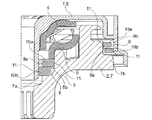
図を参照すると、バンプストップが、車体に搭載される固定式上部リテイナ1と、回転式下部リテイナ2であって、サスペンションスプリングおよび回転体(図示せず)の支持部を備えた回転式下部リテイナ2とを有する構成が示されている。該回転体は、両リテイナ間に配置されており、軸を回転軸とした両リテイナの相対的回転を可能にさせている。これによれば、スプリングが押し付けられた後、解放された場合、互いの回転の曲がりに違いが生じ、その結果下部リテイナ2の回転が誘発される。さらに、ホイール(ハンドル)を固定することによっても、下部リテイナ2の回転は誘発される。 Referring to the figure, the bump stop is a fixed upper retainer 1 and a rotary lower retainer 2 mounted on the vehicle body, and includes a suspension spring and a rotating body (not shown) supporting portion. 2 is shown. The rotating body is disposed between the retainers, and enables the retainers to rotate relative to each other with the shaft as a rotation axis. According to this, when the spring is pressed and then released, there is a difference in the bending of the mutual rotation, and as a result, the rotation of the lower retainer 2 is induced. Furthermore, the rotation of the lower retainer 2 is also induced by fixing the wheel (handle).
本実施形態では、上部リテイナ1はウォッシャ4を有しており、下部リテイナ2はウォッシャ5を有している。ウォッシャ4,5は、湾曲したシートで構成されており、それぞれに回転体の上部ベアリングおよび下部ベアリングが設けられている。
In the present embodiment, the upper retainer 1 has a washer 4, and the lower retainer 2 has a
バンプストップは、さらに2つのライニング部分6,7を有している。ライニング部分6,7は、ポリアミド6.6等の硬質熱可塑性樹脂を成形することによって形成されている。これらの部分は、それぞれ上部ウォッシャ4の付属カバー6および下部ウォッシャ5の付属支持部材7である。付属カバー6は、シャーシと該上部ウォッシャ4との間に挿入される。一方、付属支持部材7は、スプリング支持3を有している。これらのライニング部分6,7は、スプリングからの力を緩和することができ、必要に応じてバンプストップからの力も緩和することができる。
The bump stop further has two lining portions 6, 7. The lining portions 6 and 7 are formed by molding a hard thermoplastic resin such as polyamide 6.6. These portions are the attached cover 6 of the upper washer 4 and the attached support member 7 of the
本実施形態では、支持部材7はカバー6に囲まれており、それによって2つの内部輪状空間8および外部輪状空間9を形成している。各輪状空間8,9は、それぞれ内部壁面8a,9aおよび外部壁面8b,9bの側面に沿って規定されている。内部輪状空間8の内部壁面8aおよび外部壁面8bはそれぞれカバー6および支持部材7に形成されており、外部輪状空間9の内部壁面9aおよび外部壁面9bはそれぞれ支持部材7およびカバー6に形成されている。特に輪状空間8,9は、支持部材7が何の障害もなくカバー6に対して回転できるような半径方向の隙間を有している。
In the present embodiment, the support member 7 is surrounded by the cover 6, thereby forming two inner annular spaces 8 and an outer
バンプストップは、少なくとも2つの取付式封止リング10を1組としたものを有している。少なくとも2つの取付式封止リング10は軸方向に積み重ねられており、互いの間には軸方向の隙間を有している。特に封止リング10は、ポリエチレン、ポリプロピレン、ポリアミド6,6.6,11または12、あるいは、ポリオキシメチレン(POM)等を成形して形成することができる。 The bump stop has a set of at least two mounting seal rings 10. At least two mounting seal rings 10 are axially stacked with an axial gap therebetween. In particular, the sealing ring 10 can be formed by molding polyethylene, polypropylene, polyamide 6,6.6, 11 or 12, or polyoxymethylene (POM).
本実施形態では、2つの輪状空間8,9に2つの封止リング10を1組としたものが取り付けられていることによって、バンプストップの両側を封止している。しかし、内部輪状空間8または外部輪状空間9の一方のみに1組の封止リング10が取り付けられており、他方には従来から公知の封止装置が任意に取り付けられていてもよい。
In the present embodiment, two sets of two sealing rings 10 are attached to the two
封止リング10は内部壁面8a,9aまたは外部壁面8b,9bに取り付けられており、輪状空間8,9内に封止バッフルを形成するような半径方向の隙間を外部壁面8b,9bまたは内部壁面8a,9aと共に形成している。特に、バンプストップに取り付けられているバッフルは、放射状の溝を形成するための移動部材を必要としないため、カバー6および/または支持部材7の形態を制限することがない。
The sealing ring 10 is attached to the
実施形態の一例では、1組の封止リング10間の軸方向の隙間は1.2〜2.4mmの間であってもよく、半径方向の重なりは0.8〜1.6mmの間であってもよい。 In an example embodiment, the axial gap between the set of sealing rings 10 may be between 1.2 and 2.4 mm, and the radial overlap is between 0.8 and 1.6 mm. There may be.
本実施形態では、上部リング10aは支持部材7に接続されており、下部リング10bはカバー6に接続されている。あるいは、他の実施形態では、バンプストップが2つ以上の封止リング10を有しており、これらの封止リング10が軸方向の壁面8a,8bおよび9a,9bに交互に取り付けられている構成にしてもよい。これによれば、形成されるバッフルの湾曲を増すことができる。
In the present embodiment, the
少なくとも1つの封止リング10が、軸方向の移動が可能な状態で軸方向の壁面8a,8bおよび9a,9bに取り付けられていることが好適である。特にバンプストップの使用に際し、バンプストップに係る機械的な力に起因して、支持部材7に対するカバー6の歪みが生じる。その結果、双方の封止リング10は、それぞれが取り付けられている壁面上を軸方向に移動することができる。
It is preferable that at least one sealing ring 10 is attached to the
このようにして、少なくとも1つのリテイナ1,2に対する封止リング10の移動がもたらされることによって、バッフルによる封止機能と、トルク制限とを一体化することができる。さらに、封止リング10の移動は封止リング10の磨耗を制限するため、封止リング10が動かなくなり、停止による変形を引き起こすリスクを防ぐことができる。 In this way, the movement of the sealing ring 10 with respect to the at least one retainer 1, 2 is brought about, so that the sealing function by the baffle and the torque limitation can be integrated. Furthermore, since the movement of the sealing ring 10 limits the wear of the sealing ring 10, it is possible to prevent the risk that the sealing ring 10 stops moving and causes deformation due to stoppage.
本実施形態では、各リング10は軸方向の壁面8a,8bおよび9a,9b上に接続面11を有している。該接続面11の直径は上記の壁面の直径と略同等であるため、接続面11が上記の壁面上を軸方向にスライドすることが可能となる。
In this embodiment, each ring 10 has a
さらに、支持部材7は輪状部空間8,9の下をそれぞれ半径方向に伸長する2つの伸長部7a,7bを有している。これによって、1組の封止リング10を上記の空間内に保持することができる。伸長部7a,7bは封止リング10に対して、軸方向の停止機能として働いているのに加えて、各輪状空間8,9内への汚染物質の侵入を制限するために、各伸長部7a,7bは減少した隙間を介してカバー6と面している。あるいは、他の実施形態では、1組の封止リング10の保持および/または支持部材7との間の隙間の削減のために、少なくとも1つの伸長部がカバー6上に形成されている構成にすることもできる。
Further, the support member 7 has two extending
また、軸方向の壁面8a,8bおよび9a,9b上の接続の障害を削減するために、接続面11は傾斜した形状を有している。これは、自身が取り付けられている壁面8a,8bおよび9a,9bに対する封止リング10の軸方向の移動および旋回に関して好適である。
Moreover, in order to reduce the obstacle of the connection on the
以上で示したバンプストップの取り付けは、1組のリング10を支持部材7上に配置することによって実現している。上部リング10aの表面11は、上記の支持部材における軸方向の壁面8b,9aに接続されている。そしてカバー6は支持部材7上に取り付けられえており、下部リング10bの表面11と、上記のカバーにおける軸方向の壁面8a,9とを接続している。特に、形成された接続は封止リング10を引き伸ばす必要がないので、上記のリングを構成する材料の選択に制限を与えない。
The mounting of the bump stop described above is realized by arranging a set of rings 10 on the support member 7. The
本実施形態では、1組の封止リング10の直径は極めて類似しているが、1組のリング10を互いに異なる色に着色したり、および/または、上部リング10aか下部リング10bかに応じた印を設けたりする等、視覚的に間違えない工夫を施してもよい。これによって、封止リング10が区別可能になるので、該封止リング10の支持部材7への取り付け時に封止リング10を取り違える可能性を抑えることができる。
In this embodiment, the diameter of the pair of sealing rings 10 is very similar, but the pair of rings 10 may be colored differently and / or depending on whether the
Claims (10)
上部リテイナ(1)と、
下部リテイナ(2)と、
上記上部リテイナおよび上記下部リテイナの間に配置されることによって両リテイナ間の相対的回転を可能にする回転体とを備え、
上記上部リテイナおよび上記下部リテイナは、軸方向の2つの内部壁面(8a,9a)および外部壁面(8b,9b)それぞれの側面に沿って規定される少なくとも1つの輪状空間(8,9)を共に形成するように配置されており、
上記空間において互いに軸方向の隙間を介して軸方向に積み重ねられている少なくとも2つの取付式封止リング(10)を1組としたものをさらに備えており、
上記封止リングは、内部壁面(8a,9a)または外部壁面(8b,9b)に取り付けられており、上記空間内に封止バッフルを形成するような半径方向の隙間を外部壁面(8b,9b)または内部壁面(8a,9a)と共に形成していることを特徴とするバンプストップ。 Car bump stop,
Upper retainer (1),
Lower retainer (2),
A rotating body that is disposed between the upper retainer and the lower retainer to enable relative rotation between the retainers;
The upper retainer and the lower retainer together have at least one annular space (8, 9) defined along the side surfaces of the two inner wall surfaces (8a, 9a) and the outer wall surfaces (8b, 9b) in the axial direction. Are arranged to form,
Further comprising a set of at least two mounting seal rings (10) stacked in the axial direction with an axial gap therebetween in the space;
The sealing ring is attached to the inner wall surface (8a, 9a) or the outer wall surface (8b, 9b), and a radial gap that forms a sealing baffle in the space is provided on the outer wall surface (8b, 9b). ) Or an inner wall surface (8a, 9a).
上記接続面の直径は、上記壁面の直径と略同等であるため、上記接続面が上記壁面上を軸方向にスライドすることが可能であることを特徴とする請求項2に記載のバンプストップ。 The sealing ring (10) has a connection surface (11) on the axial wall surface (8a, 9a; 8b, 9b),
The bump stop according to claim 2, wherein the diameter of the connection surface is substantially the same as the diameter of the wall surface, so that the connection surface can slide in the axial direction on the wall surface.
各上記壁面は、複数の上記封止リングを1組としたものを有していることを特徴とする請求項1〜6のいずれか1項に記載のバンプストップ。 Two internal annular spaces (8) and an outer annular space (9),
The bump stop according to any one of claims 1 to 6, wherein each of the wall surfaces has a set of a plurality of the sealing rings.
さらに、2つのライニング部分として、上部の上記ウォッシャ(4)上の付属カバー(6)と、下部の上記ウォッシャ(5)下の付属支持部材(7)とを備えており、
上記輪状空間(8,9)は、上記カバーおよび上記支持部材の間に設けられていることを特徴とする請求項1〜8のいずれか1項に記載のバンプストップ。 The upper retainer (1) and the lower retainer (2) are each provided with washers (4, 5) each having an upper bearing and a lower bearing of the rotating body,
Furthermore, as two lining portions, an upper cover (6) on the upper washer (4) and an additional support member (7) below the lower washer (5) are provided.
The bump stop according to any one of claims 1 to 8, wherein the annular space (8, 9) is provided between the cover and the support member.
Applications Claiming Priority (2)
| Application Number | Priority Date | Filing Date | Title |
|---|---|---|---|
| FR1002714 | 2010-06-29 | ||
| FR1002714A FR2961747B1 (en) | 2010-06-29 | 2010-06-29 | AUTOMOTIVE VEHICLE SUSPENSION STOP COMPRISING AN ASSEMBLY OF AT LEAST TWO SEAL RINGS REPORTED |
Publications (1)
| Publication Number | Publication Date |
|---|---|
| JP2012013228A true JP2012013228A (en) | 2012-01-19 |
Family
ID=43498645
Family Applications (1)
| Application Number | Title | Priority Date | Filing Date |
|---|---|---|---|
| JP2011140471A Withdrawn JP2012013228A (en) | 2010-06-29 | 2011-06-24 | Motor vehicle bump stop comprising set of at least two mounted seal ring |
Country Status (7)
| Country | Link |
|---|---|
| US (1) | US20110317954A1 (en) |
| EP (1) | EP2402181B1 (en) |
| JP (1) | JP2012013228A (en) |
| KR (1) | KR20120001691A (en) |
| BR (1) | BRPI1102695A2 (en) |
| FR (1) | FR2961747B1 (en) |
| RU (1) | RU2562012C2 (en) |
Families Citing this family (4)
| Publication number | Priority date | Publication date | Assignee | Title |
|---|---|---|---|---|
| DE112010005238B4 (en) * | 2010-04-06 | 2020-03-26 | Aktiebolaget Skf | Thrust thrust bearing device with a sealing ring |
| US9028152B2 (en) * | 2012-12-13 | 2015-05-12 | Scheaffler Technologies AG & Co. KG | Diaphragm seal for strut bearing |
| FR3026678B1 (en) * | 2014-10-02 | 2020-04-17 | Ntn-Snr Roulements | MULTIPURPOSE MONOBLOCK CUP SUSPENSION STOP |
| FR3084016B1 (en) | 2018-07-18 | 2020-09-25 | Ntn Snr Roulements | AUTOMOTIVE VEHICLE SUSPENSION STOP |
Family Cites Families (14)
| Publication number | Priority date | Publication date | Assignee | Title |
|---|---|---|---|---|
| US2759778A (en) * | 1954-08-31 | 1956-08-21 | Norma Hoffman Bearings Corp | Sealed bearing |
| US5467971A (en) * | 1994-08-08 | 1995-11-21 | General Motors Corporation | Strut assembly with integral bearing and spring seat |
| FR2759437B1 (en) * | 1997-02-13 | 1999-05-07 | Skf France | CLUTCH MANEUVER WITH ELASTIC SELF-ALIGNMENT MEMBER |
| DE19716218C2 (en) * | 1997-04-18 | 2001-08-30 | Schaeffler Waelzlager Ohg | Clutch release bearing |
| FR2779096B1 (en) * | 1998-05-28 | 2000-12-15 | Skf France | SUSPENSION STOP DEVICE |
| DE19960699B4 (en) * | 1999-12-16 | 2010-09-30 | Schaeffler Technologies Gmbh & Co. Kg | Strut bearing |
| FR2822508B1 (en) * | 2001-03-21 | 2003-08-22 | Skf Ab | SUSPENSION STOP WITH RETAINING MEANS |
| FR2829429B1 (en) * | 2001-09-12 | 2003-12-12 | Skf Ab | STOP SUSPENSION DEVICE |
| FR2859412B1 (en) * | 2003-09-04 | 2006-02-24 | Skf Ab | STOP SUSPENSION DEVICE |
| FR2872558B1 (en) * | 2004-07-02 | 2006-09-29 | Skf Ab | CLUTCH FASTER AND METHOD OF MANUFACTURE |
| FR2904261B1 (en) * | 2006-07-26 | 2011-05-13 | Roulements Soc Nouvelle | STOPPER OF SUSPENSION AND SUSPENSION LEG WITH SUCH A ROCKET |
| RU62183U1 (en) * | 2006-10-18 | 2007-03-27 | Иосиф Яковлевич Пинус | BEARING-BEARING WITH COMBINED FRICTION COUPLE (OPTIONS) |
| FR2908849B1 (en) * | 2006-11-22 | 2009-02-13 | Snr Roulements Sa | BEARING CAGE WITH AN OBLONGED ALVEOL AND AN OBLIQUE CONTACT BALL BEARING COMPRISING SUCH A CAGE. |
| FR2918138B1 (en) * | 2007-06-29 | 2009-10-23 | Snr Roulements Sa | SUSPENSION STOP COMPRISING A MOBILE SEALING ELEMENT. |
-
2010
- 2010-06-29 FR FR1002714A patent/FR2961747B1/en not_active Expired - Fee Related
-
2011
- 2011-06-22 EP EP11171092.7A patent/EP2402181B1/en not_active Not-in-force
- 2011-06-24 JP JP2011140471A patent/JP2012013228A/en not_active Withdrawn
- 2011-06-28 US US13/170,442 patent/US20110317954A1/en not_active Abandoned
- 2011-06-28 RU RU2011126294/11A patent/RU2562012C2/en not_active IP Right Cessation
- 2011-06-29 BR BRPI1102695-2A patent/BRPI1102695A2/en not_active IP Right Cessation
- 2011-06-29 KR KR1020110063788A patent/KR20120001691A/en not_active Application Discontinuation
Also Published As
| Publication number | Publication date |
|---|---|
| FR2961747B1 (en) | 2012-08-10 |
| CN102407744A (en) | 2012-04-11 |
| EP2402181A1 (en) | 2012-01-04 |
| RU2562012C2 (en) | 2015-09-10 |
| US20110317954A1 (en) | 2011-12-29 |
| FR2961747A1 (en) | 2011-12-30 |
| EP2402181B1 (en) | 2013-06-12 |
| RU2011126294A (en) | 2013-01-10 |
| BRPI1102695A2 (en) | 2012-11-20 |
| KR20120001691A (en) | 2012-01-04 |
Similar Documents
| Publication | Publication Date | Title |
|---|---|---|
| JP6461465B2 (en) | Suspension stop with movable sealing element | |
| JP4288930B2 (en) | Plain bearing | |
| KR101572146B1 (en) | Thrust sliding bearing | |
| CN106163840B (en) | Spring-damped strut bearing with a two-component housing | |
| JP5842402B2 (en) | Thrust sliding bearing | |
| KR20140009547A (en) | Synthetic-resin plain bearing | |
| JP6602042B2 (en) | Plain bearing | |
| US8876399B2 (en) | Suspension strut bearing | |
| KR101527347B1 (en) | Synthetic resin-made sliding bearing | |
| CN110030277A (en) | Strut bearing unit and support column equipped with the unit | |
| JP2012013228A (en) | Motor vehicle bump stop comprising set of at least two mounted seal ring | |
| JP2016176600A (en) | Bearing protection system | |
| EP1681492B1 (en) | Rebound cushion for hydraulic shock absorber | |
| WO2015170586A1 (en) | Thrust sliding bearing | |
| JP2008175349A (en) | Strut bearing | |
| JP6774363B2 (en) | Bearing device for wheels | |
| JP2006322505A (en) | Thrust bearing | |
| JP4380177B2 (en) | Thrust sliding bearing | |
| US20180236837A1 (en) | Suspension Strut Bearing | |
| JP7046514B2 (en) | Sealing device | |
| CN103573829A (en) | Bearing with sealing slinger | |
| JP7164401B2 (en) | sealing device | |
| WO2016175041A1 (en) | Thrust bearing for vehicle | |
| JP2004263769A (en) | Thrust sliding bearing | |
| JP6817618B2 (en) | Magnetic encoder, sealing member and sealing device |
Legal Events
| Date | Code | Title | Description |
|---|---|---|---|
| A300 | Application deemed to be withdrawn because no request for examination was validly filed |
Free format text: JAPANESE INTERMEDIATE CODE: A300 Effective date: 20140902 |