JP6817618B2 - Magnetic encoder, sealing member and sealing device - Google Patents

Magnetic encoder, sealing member and sealing device Download PDF

Info

Publication number
JP6817618B2
JP6817618B2 JP2016192679A JP2016192679A JP6817618B2 JP 6817618 B2 JP6817618 B2 JP 6817618B2 JP 2016192679 A JP2016192679 A JP 2016192679A JP 2016192679 A JP2016192679 A JP 2016192679A JP 6817618 B2 JP6817618 B2 JP 6817618B2
Authority
JP
Japan
Prior art keywords
ring
cylinder portion
side member
fixed
seal
Prior art date
Legal status (The legal status is an assumption and is not a legal conclusion. Google has not performed a legal analysis and makes no representation as to the accuracy of the status listed.)
Active
Application number
JP2016192679A
Other languages
Japanese (ja)
Other versions
JP2018054526A (en
JP2018054526A5 (en
Inventor
浩規 石田
浩規 石田
実由子 柴田
実由子 柴田
Current Assignee (The listed assignees may be inaccurate. Google has not performed a legal analysis and makes no representation or warranty as to the accuracy of the list.)
Uchiyama Manufacturing Corp
Original Assignee
Uchiyama Manufacturing Corp
Priority date (The priority date is an assumption and is not a legal conclusion. Google has not performed a legal analysis and makes no representation as to the accuracy of the date listed.)
Filing date
Publication date
Application filed by Uchiyama Manufacturing Corp filed Critical Uchiyama Manufacturing Corp
Priority to JP2016192679A priority Critical patent/JP6817618B2/en
Publication of JP2018054526A publication Critical patent/JP2018054526A/en
Publication of JP2018054526A5 publication Critical patent/JP2018054526A5/ja
Application granted granted Critical
Publication of JP6817618B2 publication Critical patent/JP6817618B2/en
Active legal-status Critical Current
Anticipated expiration legal-status Critical

Links

Images

Landscapes

  • Transmission And Conversion Of Sensor Element Output (AREA)
  • Sealing With Elastic Sealing Lips (AREA)
  • Sealing Devices (AREA)
  • Sealing Of Bearings (AREA)
  • Rolling Contact Bearings (AREA)

Description

本発明は、例えば、自動車等の車両における車輪支持部の車両用軸受に用いられる磁気エンコーダ、シール部材及び密封装置に関する。 The present invention relates to, for example, a magnetic encoder, a sealing member, and a sealing device used for a vehicle bearing of a wheel support portion in a vehicle such as an automobile.

前記のような磁気エンコーダとしては、内輪の外周面に嵌合されるスリンガ(これと同等の部材も含む)に、周方向に複数の磁極(N極、S極)が交互に着磁された磁性ゴム(環状磁石)が固着されて回転検出用の磁気エンコーダが構成される例が示されている(例えば、特許文献1参照)。また、特許文献1にも示されているように、前記のような磁気エンコーダと、外輪の内周面に嵌合される芯金及び該芯金に固着されて前記スリンガに弾接するシールリップを有するシール部材とが組み合わさって密封装置が構成される例も知られている。 In the magnetic encoder as described above, a plurality of magnetic poles (N pole, S pole) are alternately magnetized in the circumferential direction on a slinger (including a member equivalent thereto) fitted on the outer peripheral surface of the inner ring. An example is shown in which a magnetic rubber (annular magnet) is fixed to form a magnetic encoder for rotation detection (see, for example, Patent Document 1). Further, as shown in Patent Document 1, a magnetic encoder as described above, a core metal fitted to the inner peripheral surface of the outer ring, and a seal lip fixed to the core metal and elastically contacting the slinger are provided. There is also known an example in which a sealing device is formed by combining with a sealing member having a seal member.

特開2007−285374号公報JP-A-2007-285374

ところで、特許文献1に示された磁気エンコーダにおいて、環状磁石を一体に備える金属環としてのスリンガは、内輪の外周面にのみ所定の締め代をもって嵌合されている。しかし、例えば車両走行に伴い、内輪が荷重を受けて変形を生じた場合、スリンガの内輪に対する嵌合力の偏りが生じ、エンコーダと車体側に設置された磁気センサとの相対的な位置ずれが生じて回転検出機能の精度が低下することにもなる。また、内輪の変形が大きい場合には、スリンガの内輪に対する嵌合力が弱まってエンコーダが内輪から外れる可能性も予想される。さらに、内輪に限らず、外輪の場合でも同様に変形すると、シール部材の金属環としての芯金の外輪に対する嵌合力の偏りが生じて、シールリップのスリンガに対する周方向の弾接状態が不均等になり、シール機能が低下したり回転トルクに変動を来したりすることにもなる。また、外輪の変形が大きい場合には、芯金の外輪に対する嵌合力が弱まってシール部材が外輪から外れることも予想される。このようにスリンガや芯金等の金属環は、嵌合対象の部材(回転側部材、固定側部材)が、車両走行に伴い変形した際でも、前記のような懸念が少なくなるように、スリンガや芯金を構成する金属環の取付け位置の安定化を図ることが求められていた。 By the way, in the magnetic encoder shown in Patent Document 1, the slinger as a metal ring integrally provided with an annular magnet is fitted only on the outer peripheral surface of the inner ring with a predetermined tightening allowance. However, for example, when the inner ring is deformed by receiving a load as the vehicle travels, the fitting force of the slinger with respect to the inner ring is biased, and the relative positional deviation between the encoder and the magnetic sensor installed on the vehicle body side occurs. This also reduces the accuracy of the rotation detection function. Further, when the deformation of the inner ring is large, it is expected that the fitting force of the slinger with respect to the inner ring is weakened and the encoder may come off from the inner ring. Further, if the outer ring is deformed in the same manner as the inner ring, the fitting force of the core metal as the metal ring of the seal member with respect to the outer ring is biased, and the state of impact of the seal lip with respect to the slinger in the circumferential direction is uneven. As a result, the sealing function deteriorates and the rotational torque fluctuates. Further, when the outer ring is greatly deformed, it is expected that the fitting force of the core metal with respect to the outer ring is weakened and the seal member is detached from the outer ring. In this way, the metal ring such as the slinger and the core metal is slinger so that the above-mentioned concern is reduced even when the member to be fitted (rotating side member, fixed side member) is deformed due to the running of the vehicle. It has been required to stabilize the mounting position of the metal ring constituting the core metal.

本発明は、前記実情に鑑みなされたもので、車両用軸受における取付け対象の部材に、嵌合によって取付けられる金属環の取付け位置が安定的に維持される磁気エンコーダ、シール部材及び密封装置を提供することを目的としている。 The present invention has been made in view of the above circumstances, and provides a magnetic encoder, a sealing member, and a sealing device in which a metal ring attached by fitting is stably maintained in a member to be attached in a vehicle bearing. The purpose is to do.

本発明に係る磁気エンコーダは、 車両に固定される固定側部材と、前記固定側部材に対して径方向内側に設けられるとともに該固定側部材に対して軸回転可能に支持される回転側部材とを備える車両用軸受に用いられる磁気エンコーダであって、前記回転側部材に取付けられる金属環と、周方向にN極及びS極を交互に有して前記金属環に一体に固着される環状磁石とを備え、
前記金属環は、前記回転側部材の内周面に嵌合される内側筒部と、前記回転側部材の外周面に嵌合される外側筒部と、前記内側筒部及び前記外側筒部を一体に接続する接続部と、前記外側筒部の一端部より前記回転側部材の端面側に折り返す折返し筒部と、前記折返し筒部の前記端面側の端部より径方向外向きに延出され前記環状磁石が固着される円輪部とを有し、前記外側筒部と前記内側筒部とが、径方向に延びるとともに前記接続部を構成する円板部を介して連続的に形成され、前記内側筒部及び前記外側筒部が前記回転側部材に対して嵌合された状態では前記円板部が前記端面に密着して配置され、前記環状磁石の着磁面が前記端面側に配備されていることを特徴とする。
The magnetic encoder according to the present invention includes a fixed-side member fixed to the vehicle and a rotating-side member provided radially inside the fixed-side member and supported so as to be axially rotatable with respect to the fixed-side member. A magnetic encoder used for a vehicle bearing, the annular magnet having a metal ring attached to the rotating side member and alternating north and south poles in the circumferential direction and integrally fixed to the metal ring. With and
The metal ring includes an inner cylinder portion fitted to the inner peripheral surface of the rotating side member, an outer cylinder portion fitted to the outer peripheral surface of the rotating side member, and the inner cylinder portion and the outer cylinder portion. The connecting portion to be integrally connected , the folded-back cylinder portion that folds back from one end of the outer cylinder portion to the end face side of the rotating side member, and the folded-back cylinder portion that extends outward in the radial direction from the end surface side end portion of the folded cylinder portion. It has an annular portion to which the annular magnet is fixed, and the outer tubular portion and the inner tubular portion extend in the radial direction and are continuously formed via a disc portion constituting the connecting portion. In a state where the inner cylinder portion and the outer cylinder portion are fitted to the rotation side member, the disk portion is arranged in close contact with the end face, and the magnetized surface of the annular magnet is arranged on the end face side. It has been characterized by Rukoto.

本発明の磁気エンコーダによれば、例えば車両走行時等に、回転側部材に荷重が作用して、回転側部材が径方向に変形した場合、金属環における内側筒部及び外側筒部の一方の筒部の回転側部材に対する締め代が小さくなる。しかし、内側筒部及び外側筒部の他方の筒部の回転側部材に対する締め代は大きくなる。したがって、回転側部材が径方向に変形しても、金属環に作用する嵌合力の総和が低下することが抑制され、回転側部材に対する金属環の取付け位置が安定的に維持され、金属環が回転側部材から外れることが抑制される。そして、環状磁石を備える金属環の回転側部材に対する取付け位置が安定的に維持される。その結果、磁気センサによる回転検出精度が低下することを抑制できる。また金属環を一部材で構成できるため、部品点数を増大させることなく、回転側部材に対する取付け位置が安定した磁気エンコーダとすることができる。 According to the magnetic encoder of the present invention, when a load acts on the rotating side member and the rotating side member is deformed in the radial direction, for example, when the vehicle is running, one of the inner cylinder portion and the outer cylinder portion of the metal ring The tightening allowance for the rotating member of the cylinder is reduced. However, the tightening allowance for the rotating side member of the inner cylinder portion and the other cylinder portion of the outer cylinder portion becomes large. Therefore, even if the rotating side member is deformed in the radial direction, it is suppressed that the total fitting force acting on the metal ring is suppressed, the mounting position of the metal ring with respect to the rotating side member is stably maintained, and the metal ring is formed. It is suppressed from coming off from the rotating side member. Then, the mounting position of the metal ring provided with the annular magnet with respect to the rotating side member is stably maintained. As a result, it is possible to suppress a decrease in rotation detection accuracy by the magnetic sensor. Further, since the metal ring can be composed of one member, it is possible to obtain a magnetic encoder whose mounting position with respect to the rotating side member is stable without increasing the number of parts.

本発明の密封装置によれば、車両に固定される固定側部材と、該固定側部材に対して軸回転可能に支持される回転側部材との間に存在する環状空間を密封する車両用軸受に用いられる密封装置であって、前記固定側部材に取付けられる芯金と、請求項1に記載の金属環に近接乃至は弾接するシールリップを有して前記芯金に一体に固着されたシール体とを備えたシール部材と、請求項1に記載された磁気エンコーダとが組み合わさって構成されることを特徴とする。According to the sealing device of the present invention, a bearing for a vehicle that seals an annular space existing between a fixed side member fixed to the vehicle and a rotating side member rotatably supported by the fixed side member. A seal having a core metal attached to the fixed-side member and a seal lip that is in close contact with or in contact with the metal ring according to claim 1, and is integrally fixed to the core metal. It is characterized in that the sealing member including the body and the magnetic encoder according to claim 1 are combined and configured.

本発明によれば、車両用軸受における取付け対象の部材に、嵌合によって取付けられる金属環の取付け位置が安定的に維持される磁気エンコーダ、シール部材及び密封装置を提供することができる。 According to the present invention, it is possible to provide a magnetic encoder, a sealing member, and a sealing device in which a metal ring attached by fitting is stably maintained at an attachment target member in a vehicle bearing.

本発明に係る磁気エンコーダ、シール部材及び密封装置が適用される軸受装置の一例を示す概略的縦断面図である。It is a schematic vertical sectional view which shows an example of the bearing device to which a magnetic encoder, a sealing member and a sealing device which concerns on this invention are applied. 図1のX部の拡大図であって、本発明に係る磁気エンコーダ、シール部材及び密封装置の一実施形態を示す図である。It is an enlarged view of the X part of FIG. 1, and is the figure which shows one Embodiment of the magnetic encoder, the sealing member and the sealing device which concerns on this invention. 同実施形態における回転側部材に対する磁気エンコーダの取付け態様の第一の変形例を示す要部の断面図である。It is sectional drawing of the main part which shows the 1st modification of the mounting mode of the magnetic encoder with respect to the rotating side member in the same embodiment. 同第二の変形例を示す図3と同様図である。It is the same figure as FIG. 3 which shows the 2nd modification. 同第三の変形例を示す図3と同様図である。It is the same figure as FIG. 3 which shows the 3rd modification. 同第四の変形例を示す図3と同様図である。It is the same figure as FIG. 3 which shows the 4th modification. 同第五の変形例を示す図3と同様図である。It is the same figure as FIG. 3 which shows the 5th modification. 本発明に係る磁気エンコーダ、シール部材及び密封装置が適用される軸受装置の他の例を示す概略的縦断面図である。It is a schematic vertical sectional view which shows the other example of the bearing device to which a magnetic encoder, a sealing member and a sealing device which concerns on this invention are applied. 図8のY部の拡大図であって、本発明に係る磁気エンコーダ、シール部材及び密封装置の別の実施形態を示す図である。FIG. 8 is an enlarged view of a Y portion of FIG. 8 and is a diagram showing another embodiment of the magnetic encoder, the sealing member, and the sealing device according to the present invention. 同実施形態の磁気エンコーダであって、密封装置を構成しない場合の例を示す図9と同様図である。It is the same figure as FIG. 9 which shows the example of the magnetic encoder of the same embodiment which does not form a sealing device. 同実施形態のシール部材であって、磁気エンコーダと組み合されずに密封装置を構成する例を示す図9と同様図である。It is the same figure as FIG. 9 which shows the example which is the sealing member of the same embodiment, and constitutes the sealing device without being combined with a magnetic encoder. 図8のZ部の拡大図であって、本発明に係るシール部材のさらに別の実施形態を示す図である。It is an enlarged view of the Z part of FIG. 8, and is the figure which shows still another embodiment of the seal member which concerns on this invention.

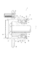
以下、本発明の実施の形態について、図面に基づいて説明する。図1は、自動車の車輪(不図示)を軸回転可能に支持する車両用軸受(軸受装置)1を示す。この軸受装置1は、外輪回転のハブベアリングであって、大略的に、ハブ輪からなる外輪(回転側部材)2と、内輪(固定側部材)3と、内輪3の車体側に嵌合一体とされる内輪部材4と、外輪2と内輪3及び内輪部材4との間に介装される2列の転動体(ボール)5…とを含んで構成される。この例では、内輪3及び内輪部材4が固定側部材とされ、内輪3が固定シャフト6にスプライン嵌合され、ナット7によって固定シャフト6に抜脱不能に一体化されている。回転側部材としての外輪2は、固定側部材としての内輪3及び内輪部材4に対して軸L回りに軸回転可能に支持され、外輪2と内輪3及び内輪部材4との間に環状空間(軸受空間)Sが形成される。環状空間としての軸受空間S内には、2列の転動体5…が、リテーナ5aに保持された状態で、外輪2の軌道輪2a、内輪3及び内輪部材4の軌道輪3a,4aを転動可能に介装されている。外輪2は、円筒形状のハブ輪本体20と、ハブ輪本体20より立上基部21を介して径方向外側に延出するよう形成されたハブフランジ22を有し、ハブフランジ22にボルト23及び不図示のナットによって従動用車輪(不図示)が取付固定される。以下において、軸L方向に沿って車輪に向く側(図1において左側を向く側)を車輪側、車体に向く側(同右側を向く側)を車体側と言う。 Hereinafter, embodiments of the present invention will be described with reference to the drawings. FIG. 1 shows a vehicle bearing (bearing device) 1 that rotatably supports wheels (not shown) of an automobile. This bearing device 1 is a hub bearing for rotating the outer ring, and is roughly fitted and integrated with the outer ring (rotating side member) 2 composed of the hub ring, the inner ring (fixed side member) 3, and the inner ring 3 on the vehicle body side. It is composed of an inner ring member 4 and two rows of rolling elements (balls) 5 ... Interposed between the outer ring 2, the inner ring 3, and the inner ring member 4. In this example, the inner ring 3 and the inner ring member 4 are fixed side members, the inner ring 3 is spline-fitted to the fixed shaft 6, and is integrally integrated with the fixed shaft 6 by a nut 7 so as not to be pulled out. The outer ring 2 as the rotating side member is supported by the inner ring 3 and the inner ring member 4 as the fixed side member so as to be axially rotatable around the axis L, and an annular space (annular space) between the outer ring 2 and the inner ring 3 and the inner ring member 4 Bearing space) S is formed. In the bearing space S as an annular space, two rows of rolling elements 5 ... Roll the raceway rings 2a of the outer ring 2, the raceway rings 3 and the raceway rings 3a, 4a of the inner ring member 4 while being held by the retainer 5a. It is movably supported. The outer ring 2 has a cylindrical hub ring main body 20 and a hub flange 22 formed so as to extend radially outward from the hub ring main body 20 via a rising base 21, and the hub flange 22 has a bolt 23 and a bolt 23. A driven wheel (not shown) is attached and fixed by a nut (not shown). In the following, the side facing the wheel (the side facing the left side in FIG. 1) along the axis L direction is referred to as the wheel side, and the side facing the vehicle body (the side facing the right side) is referred to as the vehicle body side.

軸受空間Sの軸L方向に沿った車体側端部であって、外輪2と内輪部材4との間には、ベアリングシール(密封装置)9が装着され、軸受空間Sの軸L方向に沿った車体側端部が密封される。また、ハブ輪本体20における車輪側端部の開口部にはキャップ10が装着され、軸受空間Sの車輪側端部を含むハブ輪本体20における車輪側端部の開口部が密封される。これによって、軸受空間S内への泥水等の浸入や軸受空間S内に充填される潤滑剤(グリース等)の外部への漏出が防止される。 A bearing seal (sealing device) 9 is mounted between the outer ring 2 and the inner ring member 4 at the end portion on the vehicle body side along the axis L direction of the bearing space S, and is along the axis L direction of the bearing space S. The end of the vehicle body is sealed. Further, a cap 10 is attached to the opening of the wheel side end portion of the hub wheel main body 20, and the opening of the wheel side end portion of the hub wheel main body 20 including the wheel side end portion of the bearing space S is sealed. As a result, it is possible to prevent muddy water or the like from entering the bearing space S and leakage of the lubricant (grease or the like) filled in the bearing space S to the outside.

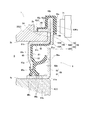
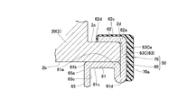
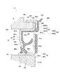
図2は、本願の第一の発明に係る磁気エンコーダ、第二の発明に係るシール部材及び第三の発明に係る密封装置の一実施形態を示す。本実施形態の磁気エンコーダ50は、ベアリングシール9の一構成部材とされている。本実施形態の磁気エンコーダ50は、外輪2(ハブ輪本体20)に取付けられる金属環60と、周方向にN極及びS極を交互に有して金属環60に一体に固着された環状磁石70とを備える。金属環60は、ハブ輪本体20(外輪2)の内周面2bに嵌合される内側筒部61と、ハブ輪本体20の外周面2cに嵌合される外側筒部62と、内側筒部61及び外側筒部62を一体に接続する接続部63とを有する。本実施形態では、さらに、金属環60は、第一部材60Aと第二部材60Bとからなる。第一部材60Aは、内側筒部61及び内側筒部61の車体側端部(一端部)61aより径方向外向きに延出された第一接続部63Aを有する。第二部材60Bは、外側筒部62及び外側筒部62の車体側端部(一端部)62aより径方向外向きに延びて折り返す折返し部62bを介して径方向内向きに延出された第二接続部63Bを有する。内側筒部61からの第一接続部63Aの延出方向と、外側筒部62からの第二接続部63Bの延出方向とが互いに向き合う関係の逆方向となる。そして、第一接続部63Aが車輪側になるとともに、第二接続部63Bが車体側になるように、接着剤64によって軸L方向に重ね合わされて一体に固着され、これにより接続部63が構成されている。このような金属環60の構成により、ハブ輪本体20の車体側の内周面2b、車体側端面2d及び車体側の外周面2cは、それぞれ金属環60の内側筒部61、接続部63を構成する第一接続部63A及び外側筒部62によって密着的に覆われている。 FIG. 2 shows an embodiment of a magnetic encoder according to the first invention of the present application, a sealing member according to the second invention, and a sealing device according to the third invention. The magnetic encoder 50 of this embodiment is a component of the bearing seal 9. The magnetic encoder 50 of the present embodiment has a metal ring 60 attached to the outer ring 2 (hub ring main body 20) and an annular magnet integrally fixed to the metal ring 60 having alternating north and south poles in the circumferential direction. 70 and. The metal ring 60 includes an inner cylinder portion 61 fitted to the inner peripheral surface 2b of the hub ring body 20 (outer ring 2), an outer cylinder portion 62 fitted to the outer peripheral surface 2c of the hub ring body 20, and an inner cylinder. It has a connecting portion 63 for integrally connecting the portion 61 and the outer tubular portion 62. In the present embodiment, the metal ring 60 is further composed of a first member 60A and a second member 60B. The first member 60A has a first connecting portion 63A extending outward in the radial direction from the inner cylinder portion 61 and the vehicle body side end portion (one end portion) 61a of the inner cylinder portion 61. The second member 60B extends radially outward from the vehicle body side end (one end) 62a of the outer tubular portion 62 and the outer tubular portion 62, and extends radially inward via a folded-back portion 62b that folds back. It has two connecting portions 63B. The extending direction of the first connecting portion 63A from the inner cylinder portion 61 and the extending direction of the second connecting portion 63B from the outer cylinder portion 62 are opposite to each other. Then, the first connecting portion 63A is on the wheel side and the second connecting portion 63B is on the vehicle body side, so that they are overlapped in the axial L direction by the adhesive 64 and fixed integrally, thereby forming the connecting portion 63. Has been done. With such a configuration of the metal ring 60, the inner peripheral surface 2b on the vehicle body side, the end surface 2d on the vehicle body side, and the outer peripheral surface 2c on the vehicle body side of the hub wheel main body 20 have the inner cylinder portion 61 and the connecting portion 63 of the metal ring 60, respectively. It is closely covered by the constituent first connecting portion 63A and the outer tubular portion 62.

また、第一部材60Aは、内側筒部61の車輪側端部61bから径方向内向きに延出された鍔状部65を有し、この鍔状部65には、後記する内輪側(固定側)金属環80に弾接するシールリップ66a,66b,66cを有するシール体66が一体に固着されている。したがって、第一部材60Aを含む金属環60とシール体66とによりシール部材67が構成される。内輪側金属環80は、円筒部81と、円筒部81の車体側端部81aから径方向外向きに延出された円輪部82とからなる断面L形に形成されている。内輪側金属環80の円筒部81は、内輪部材4の外周面4aに嵌合されている。シール体66は、ゴム等の弾性体からなり、金属環60における鍔状部65の車輪側面65aの一部から内径側端部65bを回り込んで車体側面65c及び内側筒部61の内周面61cの全面に加硫成型により一体に固着されている。シールリップ66aはアキシャルリップであり、内輪側金属環80における円輪部82の車輪側面82aに弾接している。また、シールリップ66b,66cはラジアルリップであり、円筒部81の外周面81bに先端部が互いに反方向に向くように弾接している。図2において2点鎖線で示すシールリップ66a,66b,66cは弾性変形前の原形状を示している(以下、同様)。このようにシール体66を一体に固着する第一部材60Aは、シール体66を支持する芯金の機能を奏するものとされる。 Further, the first member 60A has a collar-shaped portion 65 extending radially inward from the wheel-side end portion 61b of the inner cylinder portion 61, and the collar-shaped portion 65 has an inner ring side (fixed) described later. (Side) A seal body 66 having seal lips 66a, 66b, 66c that bounces against the metal ring 80 is integrally fixed. Therefore, the seal member 67 is composed of the metal ring 60 including the first member 60A and the seal body 66. The inner ring-side metal ring 80 is formed in an L-shaped cross section including a cylindrical portion 81 and a circular ring portion 82 extending radially outward from the vehicle body-side end portion 81a of the cylindrical portion 81. The cylindrical portion 81 of the inner ring side metal ring 80 is fitted to the outer peripheral surface 4a of the inner ring member 4. The seal body 66 is made of an elastic body such as rubber, and wraps around the inner diameter side end portion 65b from a part of the wheel side surface 65a of the flange-shaped portion 65 in the metal ring 60 to wrap around the vehicle body side surface 65c and the inner peripheral surface of the inner cylinder portion 61. It is integrally fixed to the entire surface of 61c by vulcanization molding. The seal lip 66a is an axial lip and is in contact with the wheel side surface 82a of the circular ring portion 82 of the inner ring side metal ring 80. Further, the seal lips 66b and 66c are radial lips, and are in bullet contact with the outer peripheral surface 81b of the cylindrical portion 81 so that the tip portions face in opposite directions. The seal lips 66a, 66b, 66c shown by the two-dot chain line in FIG. 2 show the original shape before elastic deformation (hereinafter, the same applies). The first member 60A for integrally fixing the seal body 66 in this way functions as a core metal for supporting the seal body 66.

環状磁石70は、磁性粉を含有するゴム磁石からなり、金属環60における第二部材60Bの第二接続部63Bに加硫成型により一体に固着されている。さらに具体的には、第二接続部63Bにおける車体側面63Baの外径側半部から折返し部62bを回り込んで外側筒部62の外周面62c及び車輪側端部62dに至る部分が前記ゴム磁石によって覆われている。そして、前記ゴム磁石における第二接続部63Bの車体側面63Baを覆う部分が環状磁石70とされ、環状磁石70の車体側面が周方向にS極及びN極が交互に着磁させれた着磁面70aとされている。この環状磁石70と金属環60とにより、磁気エンコーダ50が構成される。車体側には、この磁気エンコーダ50における環状磁石70の着磁面70aに対峙するよう磁気センサ71が設置され、磁気エンコーダ50と磁気センサ71とにより、車輪(不図示)の回転検出機構が構成される。 The annular magnet 70 is made of a rubber magnet containing magnetic powder, and is integrally fixed to the second connecting portion 63B of the second member 60B in the metal ring 60 by vulcanization molding. More specifically, the rubber magnet is formed by wrapping around the folded-back portion 62b from the outer diameter side half portion of the vehicle body side surface 63Ba of the second connecting portion 63B to reach the outer peripheral surface 62c and the wheel side end portion 62d of the outer cylinder portion 62. Covered by. The portion of the rubber magnet that covers the vehicle body side surface 63Ba of the second connecting portion 63B is an annular magnet 70, and the vehicle body side surface of the annular magnet 70 is magnetized with S poles and N poles alternately magnetized in the circumferential direction. The surface is 70a. The annular magnet 70 and the metal ring 60 constitute a magnetic encoder 50. On the vehicle body side, a magnetic sensor 71 is installed so as to face the magnetizing surface 70a of the annular magnet 70 in the magnetic encoder 50, and the magnetic encoder 50 and the magnetic sensor 71 constitute a rotation detection mechanism for wheels (not shown). Will be done.

前記のように構成される磁気エンコーダ50及びこれを一構成部材とするベアリンシール9を組付けた軸受装置1において、車両の走行に伴い車輪とともに外輪2及び磁気エンコーダ50が軸L回りに一体的に回転する。この磁気エンコーダ50の回転により、シールリップ66a,66b,66cが内輪側金属環80に弾性的に摺接する。シールリップ66a,66b,66cの内輪側金属環80に対する摺接により、外部から軸受空間S内への泥水等の浸入が阻止され、また、軸受空間S内に充填されている潤滑剤の外部漏出が防止される。また、磁気エンコーダ50の回転により、磁気センサ71が前記磁極(S極及びN極)の変化を検出し、この回転検出データが車輪の回転数や回転角度等の演算に供される。 In the bearing device 1 in which the magnetic encoder 50 configured as described above and the bearer seal 9 having the magnetic encoder 50 as one constituent member are assembled, the outer ring 2 and the magnetic encoder 50 are integrated around the axis L together with the wheels as the vehicle travels. Rotate to. The rotation of the magnetic encoder 50 causes the seal lips 66a, 66b, 66c to elastically slide into the inner ring side metal ring 80. The sliding contact of the seal lips 66a, 66b, 66c with respect to the metal ring 80 on the inner ring side prevents muddy water or the like from entering the bearing space S from the outside, and the lubricant filled in the bearing space S leaks to the outside. Is prevented. Further, as the magnetic encoder 50 rotates, the magnetic sensor 71 detects changes in the magnetic poles (S pole and N pole), and the rotation detection data is used for calculation of the number of rotations of the wheels, the rotation angle, and the like.

そして、車両走行時等に、外輪2に荷重が作用して、外輪2が径方向に変形した場合、金属環60における内側筒部61及び外側筒部62の一方の筒部の外輪2に対する締め代が小さくなる。しかし、内側筒部61及び外側筒部62の他方の筒部の外輪2に対する締め代は大きくなる。したがって、外輪2が径方向に変形しても、金属環60に作用する嵌合力の総和が低下することが抑制され、外輪2に対する金属環60の取付け位置が安定的に維持され、金属環60が外輪2から外れることが抑制される。また、環状磁石70を備える金属環60の外輪2に対する取付け位置も安定的に維持される。その結果、環状磁石70と磁気センサ71との相対位置関係も維持され、磁気センサ71による回転検出精度が低下することを抑制することができる。さらに、環状磁石70と磁気センサ71とが干渉する懸念も生じ難くなる。 Then, when a load acts on the outer ring 2 and the outer ring 2 is deformed in the radial direction during vehicle traveling or the like, tightening of one of the inner cylinder portion 61 and the outer cylinder portion 62 of the metal ring 60 with respect to the outer ring 2. The cost becomes smaller. However, the tightening allowance of the inner cylinder portion 61 and the outer cylinder portion 62 with respect to the outer ring 2 of the other cylinder portion becomes large. Therefore, even if the outer ring 2 is deformed in the radial direction, the total fitting force acting on the metal ring 60 is suppressed from decreasing, the mounting position of the metal ring 60 with respect to the outer ring 2 is stably maintained, and the metal ring 60 is maintained. Is suppressed from coming off the outer ring 2. Further, the mounting position of the metal ring 60 provided with the annular magnet 70 with respect to the outer ring 2 is also stably maintained. As a result, the relative positional relationship between the annular magnet 70 and the magnetic sensor 71 is also maintained, and it is possible to suppress a decrease in rotation detection accuracy by the magnetic sensor 71. Further, there is less concern that the annular magnet 70 and the magnetic sensor 71 interfere with each other.

また、本実施形態では、金属環60を構成する第一部材60A及び第二部材60Bは互いに別部材とされる。したがって、第一部材60Aを構成する内側筒部61及び/又は第二部材60Bを構成する外側筒部62の寸法精度(特に、外輪2に対する内側筒部61及び/又は第二部材60Bを構成する外側筒部62の径)にばらつきがあっても、その影響を互いに受けることを抑制することができる。また、第一接続部63A及び第二接続部63Bが軸L方向に重ね合わされ接着剤64によって固着されて、第一部材60A及び第二部材60Bが互いに一体に接続されているから、金属環60が外輪2から外れることがより確実に抑制される。加えて、第一接続部63A及び第二接続部63B間に接着剤64が介在することにより、第一接続部63A及び第二接続部63Bの間に泥水等が浸入することを抑制できる。さらに、本実施形態では、第二接続部63Bが、外側筒部62に対して折返し部62bを介して延出されているから、その径方向幅が大きくなり、環状磁石70の形成スペースを大きく確保できる。これにより、磁気センサ71(図2参照)の設置位置に対応させるための設計の自由度が向上する。 Further, in the present embodiment, the first member 60A and the second member 60B constituting the metal ring 60 are separate members from each other. Therefore, the dimensional accuracy of the inner cylinder portion 61 and / or the outer cylinder portion 62 constituting the second member 60B (particularly, the inner cylinder portion 61 and / or the second member 60B with respect to the outer ring 2 is formed). Even if there are variations in the diameter of the outer cylinder portion 62), it is possible to suppress the influence of each other. Further, since the first connecting portion 63A and the second connecting portion 63B are overlapped in the axial L direction and fixed by the adhesive 64, and the first member 60A and the second member 60B are integrally connected to each other, the metal ring 60 Is more reliably suppressed from coming off the outer ring 2. In addition, by interposing the adhesive 64 between the first connection portion 63A and the second connection portion 63B, it is possible to prevent muddy water or the like from entering between the first connection portion 63A and the second connection portion 63B. Further, in the present embodiment, since the second connecting portion 63B extends from the outer tubular portion 62 via the folded-back portion 62b, its radial width becomes large and the forming space of the annular magnet 70 becomes large. Can be secured. As a result, the degree of freedom in design for corresponding to the installation position of the magnetic sensor 71 (see FIG. 2) is improved.

なお、前記では、図2に示す例を本願の第一の発明に係る磁気エンコーダの一実施形態として述べたが、図2は、本願の第二の発明に係るシール部材さらには第三の発明に係る密封装置の一実施形態をも含んでいる。即ち、磁気エンコーダ50を構成する金属環60は、回転側部材及び固定側部材の一方の部材である外輪2に取付けられている。そして、当該金属環60は、回転側部材及び固定側部材の他方の部材を構成する内輪側金属環80に弾接するシールリップ66a,66b,66cを有するシール体66を固着一体に備え、金属環60とシール体66とによりシール部材67を構成している。したがって、当該シール部材67は、本願の第二の発明に係るシール部材の一実施形態とみなすことができる。また、金属環60は、磁気エンコーダ50の一部を構成するものではあるが、シール部材67をも構成することから、実質的に磁気エンコーダ50とシール部材67とが組み合わさってベアリングシール9を構成している。したがって、ベアリングシール9は本願の第三の発明に係る密封装置の一実施形態とみなすことができる。
また、図2に示す例において、シール体66を第一部材60Aに代えて内輪側金属環80に設け、シールリップ66a,66b,66cを第一部材60Aに近接乃至弾接させるようにして、金属環80とシール体66とによりシール部材を構成するようにしてもよい。
In the above, the example shown in FIG. 2 has been described as an embodiment of the magnetic encoder according to the first invention of the present application, but FIG. 2 shows the seal member and the third invention according to the second invention of the present application. It also includes one embodiment of the sealing device according to the above. That is, the metal ring 60 constituting the magnetic encoder 50 is attached to the outer ring 2 which is one of the rotating side member and the fixed side member. The metal ring 60 is integrally provided with a seal body 66 having seal lips 66a, 66b, 66c that are in contact with the inner ring side metal ring 80 that constitutes the other member of the rotating side member and the fixed side member, and is integrally provided with the metal ring. The seal member 67 is composed of the 60 and the seal body 66. Therefore, the seal member 67 can be regarded as an embodiment of the seal member according to the second invention of the present application. Further, although the metal ring 60 constitutes a part of the magnetic encoder 50, it also constitutes the seal member 67, so that the magnetic encoder 50 and the seal member 67 are substantially combined to form the bearing seal 9. It is configured. Therefore, the bearing seal 9 can be regarded as an embodiment of the sealing device according to the third invention of the present application.
Further, in the example shown in FIG. 2, the seal body 66 is provided on the inner ring side metal ring 80 instead of the first member 60A, and the seal lips 66a, 66b, 66c are brought close to or in bullet contact with the first member 60A. The seal member may be formed by the metal ring 80 and the seal body 66.

図3〜図7は、前記実施形態における外輪2に対する磁気エンコーダ50の取付け態様の変形例を示す。このうち図3〜図5に示す例は、図2に示す例と同様に金属環60が2部材からなり、図6及び図7に示す例は金属環60が一部材からなる例を示している。
なお、図3〜図7に示す例でも、図2に示すようなシール体66を有するシール部材67が存在するが、便宜上その図示を省略している。また、図2及び図3〜図7に示す金属環の構造は、他の実施形態における金属環(芯金、スリンガ)の構造にも適用することは
可能である。
3 to 7 show a modified example of the mounting mode of the magnetic encoder 50 with respect to the outer ring 2 in the embodiment. Of these, the examples shown in FIGS. 3 to 5 show an example in which the metal ring 60 is composed of two members as in the example shown in FIG. 2, and the examples shown in FIGS. 6 and 7 show an example in which the metal ring 60 is composed of one member. There is.
In the examples shown in FIGS. 3 to 7, there is a seal member 67 having a seal body 66 as shown in FIG. 2, but the illustration is omitted for convenience. Further, the structure of the metal ring shown in FIGS. 2 and 3 to 7 can be applied to the structure of the metal ring (core metal, slinger) in other embodiments.

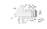
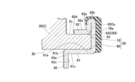
図3に示す例では、第二部材60Bを構成する第二接続部63Bが外側筒部62の車体側端部62aより径方向内向きに延出されている。つまり、図3に示す第二部材60Bは、折返し部62(図2参照)を設けることなく、外側筒部62の車体側端部62aが屈曲されて第二接続部63Bが形成されている。また、環状磁石70を構成するゴム磁石は、第二接続部63Bの車体側面63Baと内径側端縁部63Bbとを連続的に覆っている。この例では、第一部材60A及び第二部材60Bが径方向にコンパクトに構成されるから、磁気エンコーダ50の径方向の設置スペースに制約がある場合等にも好ましく適用される。
その他の構成は、図2に示す例と同様であるので、共通部分に同一の符号を付して、その説明を割愛する。
In the example shown in FIG. 3, the second connecting portion 63B constituting the second member 60B extends inward in the radial direction from the vehicle body side end portion 62a of the outer tubular portion 62. That is, in the second member 60B shown in FIG. 3, the vehicle body side end portion 62a of the outer tubular portion 62 is bent to form the second connecting portion 63B without providing the folded-back portion 62 (see FIG. 2). Further, the rubber magnet constituting the annular magnet 70 continuously covers the vehicle body side surface 63Ba and the inner diameter side edge portion 63Bb of the second connecting portion 63B. In this example, since the first member 60A and the second member 60B are compactly configured in the radial direction, it is preferably applied even when the installation space in the radial direction of the magnetic encoder 50 is limited.
Since the other configurations are the same as those shown in FIG. 2, the same reference numerals are given to the common parts, and the description thereof will be omitted.

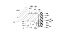
図4に示す例では、第一部材60Aを構成する第一接続部63Aが内側筒部61の車体側端部61aから径方向内向きに延出され、第二部材60Bを構成する第二接続部63Bが外側筒部62の車体側端部62aから径方向内向きに延出されている。即ち、第一接続部63A及び第二接続部63Bの延出方向が互いに同方向で、外輪2の内周面2bより内径側に突出する部分で第一接続部63A及び第二接続部63Bが軸L方向で重なり、この重なり部分で接着剤64を介して一体に固着されて接続部を構成している。また、環状磁石70を構成するゴム磁石は、第二接続部63Bの車体側面63Baと内径側端縁部63Bbとを連続的に覆っている。この例では、第二接続部63Bの径方向幅が大きくなり、環状磁石70の形成スペースを大きく確保できる。これにより、磁気センサ71(図2参照)の設置位置に対応させるための設計の自由度が向上する。
その他の構成は、図2及び図3に示す例と同様であるので、共通部分に同一の符号を付して、その説明を割愛する。
In the example shown in FIG. 4, the first connecting portion 63A constituting the first member 60A extends radially inward from the vehicle body side end portion 61a of the inner cylinder portion 61, and the second connecting portion forming the second member 60B is formed. The portion 63B extends inward in the radial direction from the vehicle body side end portion 62a of the outer tubular portion 62. That is, the first connecting portion 63A and the second connecting portion 63B extend in the same direction as each other, and the first connecting portion 63A and the second connecting portion 63B protrude toward the inner diameter side from the inner peripheral surface 2b of the outer ring 2. They overlap in the L direction of the axis, and are integrally fixed at the overlapping portion via an adhesive 64 to form a connecting portion. Further, the rubber magnet constituting the annular magnet 70 continuously covers the vehicle body side surface 63Ba and the inner diameter side edge portion 63Bb of the second connecting portion 63B. In this example, the radial width of the second connecting portion 63B is increased, and a large space for forming the annular magnet 70 can be secured. As a result, the degree of freedom in design for corresponding to the installation position of the magnetic sensor 71 (see FIG. 2) is improved.
Since the other configurations are the same as those shown in FIGS. 2 and 3, the common parts are designated by the same reference numerals and the description thereof will be omitted.

図5に示す例では、図3に示す例における第二接続部63Bの内径側端部が車輪側に延長されて屈折円筒部63Bcを有している。この屈折円筒部63Bcは、内側筒部61の内周面61cの一部にかしめられるよう形成され、このかしめによって、第一部材60Aと第二部材60Bとが一体化されている。したがって、第一接続部63Aと第二接続部63Bの軸L方向の重なり部分に接着剤64(図2、図3参照)を介さなくてもよいが、一体化をより強固にするために接着剤64を介することはもとより可能である。環状磁石70を構成するゴム磁石は、第二接続部63Bの車体側面63Baのみを覆っている。この例も、図3に示す例と同様に磁気エンコーダ50の径方向の設置スペースに制約がある場合等にも好ましく適用される。
その他の構成は、図3に示す例と同様であるので、共通部分に同一の符号を付して、その説明を割愛する。
In the example shown in FIG. 5, the inner diameter side end portion of the second connecting portion 63B in the example shown in FIG. 3 is extended to the wheel side to have the refracting cylindrical portion 63Bc. The refracting cylindrical portion 63Bc is formed so as to be crimped to a part of the inner peripheral surface 61c of the inner tubular portion 61, and the first member 60A and the second member 60B are integrated by this crimping. Therefore, it is not necessary to use the adhesive 64 (see FIGS. 2 and 3) at the overlapping portion of the first connecting portion 63A and the second connecting portion 63B in the axial L direction, but they are adhered to strengthen the integration. It is possible, of course, through the agent 64. The rubber magnet constituting the annular magnet 70 covers only the vehicle body side surface 63Ba of the second connecting portion 63B. Similar to the example shown in FIG. 3, this example is also preferably applied when the installation space in the radial direction of the magnetic encoder 50 is limited.
Since the other configurations are the same as those shown in FIG. 3, the same reference numerals are given to the common parts, and the description thereof will be omitted.

図6及び図7に示す例は、金属環60が一部材からなる例を示し、さらに具体的には、外側筒部62と内側筒部61とが、径方向に延びる円板部63Cを介して連続的に形成され、円板部63Cが接続部63を構成している。これらの例では、金属環60が一部材から構成されるから、部品点数を増大させることなく、外輪2に対する取付け位置が安定した磁気エンコーダ50とすることができる。
図6に示す例では、金属環60は、内側筒部61及び外側筒部62の他に、内側筒部61の車体側端部61aから径方向に内向きに延びて折り返す折返し部61dと、折返し部61dを介して径方向外向きに延出された円板部63Cとを備える。円板部63Cは、外側筒部62の車体側端部62aに連続するように形成されている。そして、環状磁石70を構成するゴム磁石は、円板部63Cの車体側面63Caの全面から外側筒部62の外周面62c及び車輪側端部62dを覆っている。この例では、円板部63Cが内側筒部61の車体側端部61aより折返し部61dを介して形成されているから、円板部63Cの径方向幅が外輪2の車体側端面2dの径方向幅より大きく、環状磁石70の形成スペースを大きく確保できる。これにより、磁気センサ71(図2参照)の設置位置に対応させるための設計の自由度が向上する。
The examples shown in FIGS. 6 and 7 show an example in which the metal ring 60 is made of one member, and more specifically, the outer cylinder portion 62 and the inner cylinder portion 61 are interposed via a disc portion 63C extending in the radial direction. The disk portion 63C constitutes the connecting portion 63. In these examples, since the metal ring 60 is composed of one member, the magnetic encoder 50 having a stable mounting position with respect to the outer ring 2 can be obtained without increasing the number of parts.
In the example shown in FIG. 6, in addition to the inner cylinder portion 61 and the outer cylinder portion 62, the metal ring 60 includes a folded-back portion 61d that extends inward in the radial direction from the vehicle body side end portion 61a of the inner cylinder portion 61 and is folded back. It includes a disk portion 63C extending outward in the radial direction via the folded-back portion 61d. The disk portion 63C is formed so as to be continuous with the vehicle body side end portion 62a of the outer tubular portion 62. The rubber magnet constituting the annular magnet 70 covers the outer peripheral surface 62c of the outer tubular portion 62 and the wheel side end portion 62d from the entire surface of the vehicle body side surface 63Ca of the disc portion 63C. In this example, since the disk portion 63C is formed from the vehicle body side end portion 61a of the inner cylinder portion 61 via the folded-back portion 61d, the radial width of the disk portion 63C is the diameter of the vehicle body side end surface 2d of the outer ring 2. It is larger than the directional width, and a large space for forming the annular magnet 70 can be secured. As a result, the degree of freedom in design for corresponding to the installation position of the magnetic sensor 71 (see FIG. 2) is improved.

図7に示す例では、金属環60は、内側筒部61及び外側筒部62の他に、外側筒部62の車体側端部62aから径方向に外向きに延びて折り返す折返し部62bと、折返し部62bを介して径方向内向きに延出された円板部63Cとを備える。円板部63Cは、内側筒部61の車体側端部61aに連続するように形成されている。そして、環状磁石70を構成するゴム磁石は、円板部63Cの車体側面63Caの全面から折返し部62bを回り込むように覆っている。この例では、円板部63Cが外側筒部62の車体側端部62aより折返し部62bを介して形成されているから、円板部63Cの径方向幅が外輪2の車体側端面2dの径方向幅より大きく、図6の例と同様に環状磁石70の形成スペースを大きく確保できる。これにより、磁気センサ71(図2参照)の設置位置に対応させるための設計の自由度が向上する。
なお、図6及び図7に示す例において、折返し部61d(62b)を介さず内側筒部61の車体側端部61aと外側筒部52の車体側端部62aに直接連なる円板部を接続部としてもよい。図6及び図7に示す例のその他の構成は図2に示す例と同様であるから、共通部分に同一の符号を付して、その説明を割愛する。
In the example shown in FIG. 7, in addition to the inner cylinder portion 61 and the outer cylinder portion 62, the metal ring 60 includes a folded-back portion 62b that extends outward in the radial direction from the vehicle body side end portion 62a of the outer cylinder portion 62 and is folded back. It includes a disk portion 63C extending inward in the radial direction via the folded-back portion 62b. The disk portion 63C is formed so as to be continuous with the vehicle body side end portion 61a of the inner cylinder portion 61. The rubber magnet constituting the annular magnet 70 covers the folded-back portion 62b from the entire surface of the vehicle body side surface 63Ca of the disk portion 63C so as to wrap around. In this example, since the disk portion 63C is formed from the vehicle body side end portion 62a of the outer cylinder portion 62 via the folded-back portion 62b, the radial width of the disk portion 63C is the diameter of the vehicle body side end surface 2d of the outer ring 2. It is larger than the directional width, and a large space for forming the annular magnet 70 can be secured as in the example of FIG. As a result, the degree of freedom in design for corresponding to the installation position of the magnetic sensor 71 (see FIG. 2) is improved.
In the examples shown in FIGS. 6 and 7, a disk portion directly connected to the vehicle body side end portion 61a of the inner cylinder portion 61 and the vehicle body side end portion 62a of the outer cylinder portion 52 is connected without passing through the folded-back portion 61d (62b). It may be a department. Since the other configurations of the examples shown in FIGS. 6 and 7 are the same as those shown in FIG. 2, the same reference numerals are given to the common parts, and the description thereof will be omitted.

図8は、本発明に係る磁気エンコーダ、シール部材及び密封装置が適用される軸受装置の他の例を示す。この例の軸受装置11は、内輪回転のハブベアリングであって、大略的に、外輪12と、ハブ輪13と、ハブ輪13の車体側に嵌合一体とされる内輪部材14と、外輪12とハブ輪13及び内輪部材14との間に介装される2列の転動体(ボール)16…とを含んで構成される。この例では、ハブ輪13及び内輪部材14が内輪15を構成し、外輪12は、自動車の車体(不図示)に固定される。また、ハブ輪13にはドライブシャフト17が同軸的にスプライン嵌合され、ドライブシャフト17は等速ジョイント18を介して不図示の駆動源(駆動伝達部)に連結される。ドライブシャフト17はナット19によって、ハブ輪13と一体化され、ハブ輪13のドライブシャフト17からの抜脱が防止されている。回転側部材としての内輪15(ハブ輪13及び内輪部材14)は固定側部材としての外輪12に対して、軸L1回りに回転(軸回転)可能とされ、外輪12と、内輪15との間に環状空間(軸受空間)S1が形成される。環状空間としての軸受空間S1内には、2列の転動体16…が、リテーナ16aに保持された状態で、外輪12の軌道輪12a、ハブ輪13の軌道輪13a及び内輪部材14の軌道輪14aを転動可能に介装されている。ハブ輪13は、円筒形状のハブ輪本体130と、ハブ輪本体130より立上基部131を介して径方向外側に延出されたハブフランジ132を有し、ハブフランジ132にボルト133及び不図示のナットによって駆動用車輪が取付固定される。以下においても、軸L1方向に沿って車輪に向く側(図8において左側を向く側)を車輪側、車体に向く側(同右側を向く側)を車体側と言う。 FIG. 8 shows another example of the bearing device to which the magnetic encoder, the sealing member and the sealing device according to the present invention are applied. The bearing device 11 of this example is a hub bearing that rotates an inner ring, and is roughly an outer ring 12, a hub ring 13, an inner ring member 14 that is fitted and integrated on the vehicle body side of the hub ring 13, and an outer ring 12. It is composed of two rows of rolling elements (balls) 16 ... Interposed between the hub wheel 13 and the inner ring member 14. In this example, the hub wheel 13 and the inner ring member 14 form the inner ring 15, and the outer ring 12 is fixed to the vehicle body (not shown) of the automobile. Further, the drive shaft 17 is coaxially spline-fitted to the hub wheel 13, and the drive shaft 17 is connected to a drive source (drive transmission unit) (not shown) via a constant velocity joint 18. The drive shaft 17 is integrated with the hub wheel 13 by the nut 19, and the hub wheel 13 is prevented from being pulled out from the drive shaft 17. The inner ring 15 (hub ring 13 and inner ring member 14) as the rotating side member can rotate (shaft rotation) around the shaft L1 with respect to the outer ring 12 as the fixed side member, and is between the outer ring 12 and the inner ring 15. An annular space (bearing space) S1 is formed in the ring space (bearing space) S1. In the bearing space S1 as an annular space, two rows of rolling elements 16 ... Are held by the retainer 16a, and the raceway ring 12a of the outer ring 12, the raceway ring 13a of the hub ring 13, and the raceway ring of the inner ring member 14 are held. 14a is rotatably intervened. The hub wheel 13 has a cylindrical hub wheel main body 130 and a hub flange 132 extending radially outward from the hub wheel main body 130 via a rising base 131, and a bolt 133 and a bolt 133 are not shown on the hub flange 132. The drive wheels are mounted and fixed by the nuts. Also in the following, the side facing the wheel (the side facing the left side in FIG. 8) along the axis L1 direction is referred to as the wheel side, and the side facing the vehicle body (the side facing the right side) is referred to as the vehicle body side.

内輪15には、等速ジョイント18及びドライブシャフト17を介して駆動源から回転力が伝達され、これによって内輪15及び車輪(駆動輪)が回転する。軸受空間S1の軸L1方向に沿った両端部であって、外輪12とハブ輪13との間、及び、外輪12と内輪部材14との間には、ベアリングシール90,100が装着され、軸受空間S1の軸L方向に沿った両端部が密封される。これによって、軸受空間S1内への泥水等の浸入や軸受空間S1内に充填される潤滑剤(グリース等)の外部への漏出が防止される。 A rotational force is transmitted to the inner ring 15 from a drive source via a constant velocity joint 18 and a drive shaft 17, whereby the inner ring 15 and wheels (drive wheels) rotate. Bearing seals 90 and 100 are mounted between the outer ring 12 and the hub ring 13 and between the outer ring 12 and the inner ring member 14 at both ends of the bearing space S1 along the axis L1 direction. Both ends of the space S1 along the axis L direction are sealed. This prevents muddy water and the like from entering the bearing space S1 and the lubricant (grease and the like) filled in the bearing space S1 from leaking to the outside.

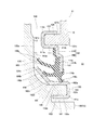
図9は、本発明に係る磁気エンコーダ、シール部材及び密封装置の別の実施形態を示す。図9におけるベアリングシール90は、本願の第三の発明に係る密封装置の別の実施形態であることを示している。本実施形態のベアリングシール(密封装置)90は、回転側部材としての内輪15(内輪部材14)に取り付けられた磁気エンコーダ91と、外輪12の車体側端部120に取り付けられたシール部材95とから構成される。磁気エンコーダ91は、本願の第一の発明に係る磁気エンコーダの別の実施であることを示している。また、シール部材95は、本願の第二の発明に係るシール部材の別の実施であることを示している。 FIG. 9 shows another embodiment of the magnetic encoder, the sealing member, and the sealing device according to the present invention. The bearing seal 90 in FIG. 9 shows that it is another embodiment of the sealing device according to the third invention of the present application. The bearing seal (sealing device) 90 of the present embodiment includes a magnetic encoder 91 attached to an inner ring 15 (inner ring member 14) as a rotating side member, and a sealing member 95 attached to a vehicle body side end 120 of the outer ring 12. Consists of. The magnetic encoder 91 shows that it is another embodiment of the magnetic encoder according to the first invention of the present application. Further, the seal member 95 shows that it is another implementation of the seal member according to the second invention of the present application.

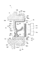
磁気エンコーダ91は、内輪部材14に取付けられる金属環としてのスリンガ92と、スリンガ92における後記する円輪部925の車体側面925aに固着された環状磁石93とからなる。金属環としてのスリンガ92は、回転側部材としての内輪部材14の内周面14aに嵌合される内側筒部921と、内輪部材14の外周面14bに嵌合される外側筒部922と、内側筒部921及び外側筒部922を一体に接続する接続部923とを有する。さらに本実施形態のスリンガ92は、外側筒部922の車輪側端部922bより車体側に折り返す折返し筒部924と、折返し筒部924の車体側端部924aより径方向外向きに延出された円輪部925とを有している。接続部923は、内側筒部921の車体側端部(一端部)921aと外側筒部922の車体側端部(一端部)922aとに連続する円板部とされ、内側筒部921及び外側筒部922の内輪部材14に対する嵌合状態では内輪部材14の車体側端面14cに密着する。環状磁石93は、磁性粉を含有するゴム磁石からなり、スリンガ92における円輪部925の車体側面925aに加硫成型により一体に固着され、その車体側面が、周方向に沿ってN極及びS極が交互に着磁された着磁面93aとされている。車体側には、環状磁石93の着磁面93aに対峙するように磁気センサ931が設置されている。
なお、内輪部材14におけるスリンガ92が嵌合される部分は、車体側に突出する円筒形状をなすように形成されている。
The magnetic encoder 91 includes a slinger 92 as a metal ring attached to the inner ring member 14, and an annular magnet 93 fixed to a vehicle body side surface 925a of a circular ring portion 925 described later in the slinger 92. The slinger 92 as a metal ring includes an inner tubular portion 921 fitted to the inner peripheral surface 14a of the inner ring member 14 as a rotating side member, and an outer tubular portion 922 fitted to the outer peripheral surface 14b of the inner ring member 14. It has a connecting portion 923 that integrally connects the inner tubular portion 921 and the outer tubular portion 922. Further, the slinger 92 of the present embodiment extends outward in the radial direction from the folded-back cylinder portion 924 that folds back toward the vehicle body side from the wheel-side end portion 922b of the outer tubular portion 922 and the vehicle body-side end portion 924a of the folded cylinder portion 924. It has an annular portion 925. The connecting portion 923 is a disk portion continuous with the vehicle body side end (one end) 921a of the inner cylinder portion 921 and the vehicle body side end (one end) 922a of the outer cylinder 922, and the inner cylinder portion 921 and the outer side. In the fitted state of the tubular portion 922 with respect to the inner ring member 14, the inner ring member 14 is in close contact with the vehicle body side end surface 14c. The annular magnet 93 is made of a rubber magnet containing magnetic powder, and is integrally fixed to the vehicle body side surface 925a of the annular portion 925 of the slinger 92 by vulcanization molding, and the vehicle body side surface is integrally fixed to the north pole and S along the circumferential direction. The magnetized surface 93a is such that the poles are magnetized alternately. On the vehicle body side, a magnetic sensor 931 is installed so as to face the magnetizing surface 93a of the annular magnet 93.
The portion of the inner ring member 14 to which the slinger 92 is fitted is formed so as to form a cylindrical shape protruding toward the vehicle body.

シール部材95は、回転側部材及び固定側部材の一方の部材である外輪12の車体側端部120に取り付けられる金属環としての芯金96と、芯金96に一体に固着されたシール体97とからなる。金属環としての芯金96は、外輪12における車体側端部120の内周面120aに嵌合される内側筒部961と、車体側端部120の外周面120bに嵌合される外側筒部962と、内側筒部961及び外側筒部962を一体に接続する接続部963とを有する。さらに、本実施形態の芯金96は、内側筒部961の車輪側端部961bから径方向内向きに延出された鍔状部965を有している。接続部963は、内側筒部961の車体側端部(一端部)961aと外側筒部962の車体側端部(一端部)962aとに連続する円板部とされる。接続部963は、内側筒部961及び外側筒部962の外輪12における車体側端部120に対する嵌合状態では車体側端部120の車体側端面120cに密着する。シール体97は、ゴム等の弾性体からなり、スリンガ92における円輪部925の車輪側面925bに弾接するアキシャルリップ(シールリップ)97aと、折返し筒部924の外周面924bに先端部が互いに反方向に向くよう弾接する2個のラジアルリップ(シールリップ)97b,97cとを有している。この場合、スリンガ92は、回転側部材及び固定側部材の他方の部材の一部に相当する。シール体97は、芯金96における鍔状部965の車輪側面965aの一部から内径側端部965bを回り込んで車体側面965c及び内側筒部961の内周面961cの全面と、接続部963の車体側面963aの一部に加硫成型により一体に固着されている。 The seal member 95 includes a core metal 96 as a metal ring attached to the vehicle body side end 120 of the outer ring 12, which is one of the rotating side member and the fixed side member, and a seal body 97 integrally fixed to the core metal 96. It consists of. The core metal 96 as a metal ring has an inner cylinder portion 961 fitted to the inner peripheral surface 120a of the vehicle body side end portion 120 of the outer ring 12 and an outer cylinder portion fitted to the outer peripheral surface 120b of the vehicle body side end portion 120. It has a 962 and a connecting portion 963 that integrally connects the inner tubular portion 961 and the outer tubular portion 962. Further, the core metal 96 of the present embodiment has a collar-shaped portion 965 extending inward in the radial direction from the wheel side end portion 961b of the inner tubular portion 961. The connecting portion 963 is a disk portion continuous with the vehicle body side end portion (one end portion) 961a of the inner cylinder portion 961 and the vehicle body side end portion (one end portion) 962a of the outer cylinder portion 962. The connecting portion 963 is in close contact with the vehicle body side end surface 120c of the vehicle body side end portion 120 in the fitted state with respect to the vehicle body side end portion 120 of the outer ring 12 of the inner cylinder portion 961 and the outer cylinder portion 962. The seal body 97 is made of an elastic body such as rubber, and its tips are opposed to each other by the axial lip (seal lip) 97a which is in contact with the wheel side surface 925b of the circular ring portion 925 of the slinger 92 and the outer peripheral surface 924b of the folded cylinder portion 924. It has two radial lips (seal lips) 97b and 97c that are in contact with each other so as to face in the direction. In this case, the slinger 92 corresponds to a part of the other member of the rotating side member and the fixed side member. The seal body 97 wraps around the inner diameter side end portion 965b from a part of the wheel side surface 965a of the flange-shaped portion 965 in the core metal 96, and covers the entire surface of the vehicle body side surface 965c and the inner peripheral surface 961c of the inner cylinder portion 961 and the connecting portion 963. It is integrally fixed to a part of the vehicle body side surface 963a by vulcanization molding.

前記のように構成されるベアリンシール90を組付けた軸受装置11において、ドライブシャフト17(図8参照)の駆動回転に伴い内輪15及び磁気エンコーダ91が軸L1回りに一体的に回転する。この磁気エンコーダ91の回転により、シールリップ97a,97b,97cがスリンガ92に弾性的に相対摺接する。シールリップ97a,97b,97cのスリンガ92に対する弾性的相対摺接により、外部から軸受空間S1内への泥水等の浸入が阻止され、また、軸受空間S1内に充填されている潤滑剤の外部漏出が防止される。また、磁気エンコーダ91の回転により、磁気センサ931が前記磁極(S極及びN極)の変化を検出し、この回転検出データが車輪の回転数や回転角度等の演算に供される。 In the bearing device 11 to which the bearlin seal 90 configured as described above is assembled, the inner ring 15 and the magnetic encoder 91 rotate integrally around the shaft L1 with the drive rotation of the drive shaft 17 (see FIG. 8). The rotation of the magnetic encoder 91 causes the seal lips 97a, 97b, and 97c to elastically slide relative to the slinger 92. The elastic relative sliding contact of the seal lips 97a, 97b, 97c with respect to the slinger 92 prevents muddy water and the like from entering the bearing space S1 from the outside, and leaks the lubricant filled in the bearing space S1 to the outside. Is prevented. Further, due to the rotation of the magnetic encoder 91, the magnetic sensor 931 detects a change in the magnetic poles (S pole and N pole), and this rotation detection data is used for calculation of the number of rotations of the wheels, the rotation angle, and the like.

そして、車両走行時等に、内輪15に荷重が作用して、内輪15が径方向に変形した場合、スリンガ(金属環)92における内側筒部921及び外側筒部922の一方の筒部の内輪15(内輪部材14)に対する締め代が小さくなる。しかし、内側筒部921及び外側筒部922の他方の筒部の内輪15(内輪部材14)に対する締め代が大きくなる。したがって、内輪15が径方向に変形しても、スリンガ92に作用する嵌合力の総和が低下することが抑制され、内輪15に対するスリンガ92の取付け位置が安定的に維持され、スリンガ92が内輪15から外れることが抑制される。その結果、スリンガ92に固着される環状磁石93と磁気センサ931との相対位置も維持され、磁気センサ931による回転検出精度が低下することを抑制することができる。さらに、環状磁石93と磁気センサ931とが干渉する懸念も生じ難くなる。 Then, when a load acts on the inner ring 15 and the inner ring 15 is deformed in the radial direction when the vehicle is running or the like, the inner ring of one of the inner cylinder portion 921 and the outer cylinder portion 922 in the slinger (metal ring) 92 is formed. The tightening allowance for 15 (inner ring member 14) is reduced. However, the tightening allowance for the inner ring 15 (inner ring member 14) of the other cylinder portion of the inner cylinder portion 921 and the outer cylinder portion 922 becomes large. Therefore, even if the inner ring 15 is deformed in the radial direction, the total fitting force acting on the slinger 92 is suppressed from being lowered, the mounting position of the slinger 92 with respect to the inner ring 15 is stably maintained, and the slinger 92 is attached to the inner ring 15. It is suppressed to deviate from. As a result, the relative position between the annular magnet 93 fixed to the slinger 92 and the magnetic sensor 931 is also maintained, and it is possible to suppress a decrease in the rotation detection accuracy of the magnetic sensor 931. Further, there is less concern that the annular magnet 93 and the magnetic sensor 931 interfere with each other.

また、車両走行時に、外輪12に荷重が作用して、外輪12が径方向に変形した場合、芯金(金属環)96における内側筒部961及び外側筒部962の一方の筒部の外輪12に対する締め代が小さくなる。しかし、内側筒部961及び外側筒部962の他方の筒部の外輪12に対する締め代は大きくなる。したがって、外輪12が径方向に変形しても、芯金96に作用する嵌合力の総和が低下することが抑制され、外輪12に対する芯金96の取付け位置が安定的に維持され、芯金96が外輪12から外れることが抑制される。そして、シール体97が固着される芯金96の取付け位置が安定的に維持されるから、シールリップ97a,97b,97cが相対摺接するスリンガ96との相対的位置関係も維持され、シールリップ97a,97b,97cによるシール機能が低下することが抑制され、シール体97によるシール機能が精度よく維持される。また、シールリップ97a,97b,97cのスリンガ96に対する相対摺接に伴う回転トルクの変動も生じ難くなる。 Further, when a load acts on the outer ring 12 and the outer ring 12 is deformed in the radial direction during vehicle traveling, the outer ring 12 of one of the inner cylinder portion 961 and the outer cylinder portion 962 in the core metal (metal ring) 96. The tightening allowance is smaller. However, the tightening allowance of the inner cylinder portion 961 and the outer cylinder portion 962 with respect to the outer ring 12 of the other cylinder portion becomes large. Therefore, even if the outer ring 12 is deformed in the radial direction, the total fitting force acting on the core metal 96 is suppressed from decreasing, the mounting position of the core metal 96 with respect to the outer ring 12 is stably maintained, and the core metal 96 is maintained. Is suppressed from coming off the outer ring 12. Since the mounting position of the core metal 96 to which the seal body 97 is fixed is stably maintained, the relative positional relationship with the slinger 96 with which the seal lips 97a, 97b, and 97c are in relative sliding contact is also maintained, and the seal lip 97a is maintained. , 97b, 97c suppresses the deterioration of the sealing function, and the sealing function of the sealing body 97 is maintained with high accuracy. Further, the fluctuation of the rotational torque due to the relative sliding contact of the seal lips 97a, 97b, 97c with respect to the slinger 96 is less likely to occur.

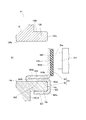
図10は、本願の第一の発明に係る磁気エンコーダの別の実施形態であって、密封装置を構成しない磁気エンコーダの例を示している。内輪回転の軸受装置において、このように密封装置を構成しない磁気エンコーダ91が採用される例としては、当該磁気エンコーダ91より軸受空間S1側に別のベアリングシールが組付けられる場合が挙げられる。或いは、従動輪用軸受装置で外輪12の車体側開口部が有底筒状のキャップで封止され、環状磁石93と磁気センサ931と間にキャップが位置するように磁気センサ931が設置される場合等も挙げられる。
本実施形態の磁気エンコーダ91の構成は、図9に示す例と同様である。したがって、この場合も、内輪15(内輪部材14)が径方向に変形しても、スリンガ92に作用する嵌合力の総和が低下することが抑制され、内輪15に対するスリンガ92の取付け位置が安定的に維持され、スリンガ92が内輪15から外れることが抑制される。その結果、スリンガ92の固着される環状磁石93と磁気センサ931との相対位置も維持され、磁気センサ931による回転検出精度が低下することを抑制することができる。さらに、環状磁石93と磁気センサ931とが干渉する懸念も生じ難くなる。
その他の構成は、図9に示す例と同様であるので、共通部分に同一の符号を付し、その説明を割愛する。
FIG. 10 shows another embodiment of the magnetic encoder according to the first invention of the present application, which is an example of a magnetic encoder that does not constitute a sealing device. As an example in which the magnetic encoder 91 that does not constitute the sealing device is adopted in the bearing device for inner ring rotation, there is a case where another bearing seal is assembled on the bearing space S1 side from the magnetic encoder 91. Alternatively, the bearing device for the driven wheel seals the opening on the vehicle body side of the outer ring 12 with a bottomed tubular cap, and the magnetic sensor 931 is installed so that the cap is located between the annular magnet 93 and the magnetic sensor 931. There are also cases.
The configuration of the magnetic encoder 91 of this embodiment is the same as the example shown in FIG. Therefore, also in this case, even if the inner ring 15 (inner ring member 14) is deformed in the radial direction, it is suppressed that the total fitting force acting on the slinger 92 decreases, and the mounting position of the slinger 92 with respect to the inner ring 15 is stable. The slinger 92 is prevented from coming off the inner ring 15. As a result, the relative position between the annular magnet 93 to which the slinger 92 is fixed and the magnetic sensor 931 is also maintained, and it is possible to suppress a decrease in the rotation detection accuracy by the magnetic sensor 931. Further, there is less concern that the annular magnet 93 and the magnetic sensor 931 interfere with each other.
Since the other configurations are the same as those shown in FIG. 9, the same reference numerals are given to the common parts, and the description thereof will be omitted.

図11は、本願の第二の発明に係るシール部材の別の実施形態であって、磁気エンコーダを構成しないスリンガと組み合わさって密封装置を構成するシール部材の例を示している。本実施形態のシール部材95は、内輪部材14に嵌合されるスリンガ98と組合わさってベアリングシール(密封装置)90Aを構成する。スリンガ98は、断面L字形状であり、内輪部材14の外周面14bに嵌合される円筒部981と、円筒部981の車体側端部981aから径方向外向きに延びる円輪部982とからなる。 FIG. 11 shows another embodiment of the sealing member according to the second invention of the present application, which is an example of a sealing member that constitutes a sealing device in combination with a slinger that does not form a magnetic encoder. The seal member 95 of the present embodiment constitutes a bearing seal (sealing device) 90A in combination with a slinger 98 fitted to the inner ring member 14. The slinger 98 has an L-shaped cross section, and is composed of a cylindrical portion 981 fitted to the outer peripheral surface 14b of the inner ring member 14, and a circular ring portion 982 extending radially outward from the vehicle body side end portion 981a of the cylindrical portion 981. Become.

本実施形態のシール部材95は、図9に示すシール部材とは、金属環としての芯金96及びシール体97の形成態様が若干異なる。即ち、本実施形態の芯金(金属環)96は、内側筒部961及び内側筒部961の車体側端部(一端部)961aから径方向外向きに延出された第一接続部963Aを有する第一部材960Aと、外側筒部962及び外側筒部962の車体側端部(一端部)962aから径方向内向きに延出された第二部材960Bとからなる。そして、第一接続部963A及び第二接続部963Bが、第二接続部963Bが車体側になるように軸L1(図8参照)方向に重なって接続部材963を構成している。第一接続部963Aと第二接続部963Bとは接着剤964を介して一体に固着されている。この芯金96の外輪12(車体側端部120)に対する嵌合状態では、第一接続部963Aが、車体側端部120の車体側端面120cに密着している。また、芯金96は、図9に示す例と同様に、内側筒部961の車輪側端部961bから径方向内向きに延出された鍔状部965を有している。 The seal member 95 of the present embodiment is slightly different from the seal member shown in FIG. 9 in the form of the core metal 96 as the metal ring and the seal body 97. That is, the core metal (metal ring) 96 of the present embodiment is a first connecting portion 963A extending outward in the radial direction from the vehicle body side end portion (one end portion) 961a of the inner cylinder portion 961 and the inner cylinder portion 961. The first member 960A is composed of a first member 960A and a second member 960B extending inward in the radial direction from the vehicle body side end portion (one end portion) 962a of the outer tubular portion 962 and the outer tubular portion 962. Then, the first connection portion 963A and the second connection portion 963B overlap in the direction of the shaft L1 (see FIG. 8) so that the second connection portion 963B is on the vehicle body side to form the connection member 963. The first connecting portion 963A and the second connecting portion 963B are integrally fixed via an adhesive 964. In the fitted state of the core metal 96 with respect to the outer ring 12 (vehicle body side end portion 120), the first connecting portion 963A is in close contact with the vehicle body side end surface 120c of the vehicle body side end portion 120. Further, the core metal 96 has a collar-shaped portion 965 extending inward in the radial direction from the wheel side end portion 961b of the inner tubular portion 961 as in the example shown in FIG.

一方、シール体97は、前記芯金96における鍔状部965の車輪側面965aの一部から内径側端部965bを回り込んで車体側面965c及び内側筒部961の内周面961cの全面と、第二接続部963Bの車体側面963Baの全面に加硫成型により一体に固着されている。また、シール体97は、スリンガ98における円輪部982の車輪側面982aに弾接するアキシャルリップ(シールリップ)97aと、円筒部981の外周面981bに、先端部が互いに反方向に向くよう弾接する2個のラジアルリップ(シールリップ)97b,97cとを有している。さらに本実施形態では、シール体97の最外径側部分に、車体側に向け拡径するリップ97dを有しており、このリップ97dは、図示を省略する車体の構成部分に近接乃至弾接して、ベアリングシール90A内への泥水等の浸入を防止するべく機能する。本例においても、外輪12が回転側部材及び固定側部材の一方の部材であり、スリンガ98を有する内輪15(内輪部材14)が回転側部材及び固定側部材の他方の部材である。
その他の構成は、図9に示すシール部材と同様であるから、共通部分に同一の符号を付し、その説明を割愛する。
On the other hand, the seal body 97 wraps around the inner diameter side end portion 965b from a part of the wheel side surface 965a of the collar-shaped portion 965 in the core metal 96, and covers the entire surface of the vehicle body side surface 965c and the inner peripheral surface 961c of the inner cylinder portion 961. The second connecting portion 963B is integrally fixed to the entire surface of the vehicle body side surface 963Ba by vulcanization molding. Further, the seal body 97 is in contact with the axial lip (seal lip) 97a that comes into contact with the wheel side surface 982a of the circular ring portion 982 in the slinger 98 and the outer peripheral surface 981b of the cylindrical portion 981 so that the tip portions face each other in opposite directions. It has two radial lips (seal lips) 97b and 97c. Further, in the present embodiment, the outermost diameter side portion of the seal body 97 has a lip 97d whose diameter increases toward the vehicle body side, and the lip 97d is in close proximity to or in bullet contact with a component portion of the vehicle body (not shown). Therefore, it functions to prevent muddy water and the like from entering the bearing seal 90A. Also in this example, the outer ring 12 is one member of the rotating side member and the fixed side member, and the inner ring 15 (inner ring member 14) having the slinger 98 is the other member of the rotating side member and the fixed side member.
Since the other configurations are the same as those of the seal member shown in FIG. 9, the same reference numerals are given to the common parts, and the description thereof will be omitted.

図12は、図8のZ部の拡大図であって、本発明に係るシール部材のさらに別の実施形態を示す。本実施形態のシール部材101は、ハブフランジ132側(車輪側)のベアリングシール(密封装置)100を構成し、回転側部材及び固定側部材の一方の部材としての外輪12に取付けられる芯金(金属環)110と、芯金110に一体に固着されたシール体150とを有する。芯金110は、外輪12における車輪側端部121の内周面121aに嵌合される内側筒部111と、車輪側端部121の外周面121bに嵌合される外側筒部112と、内側筒部111及び外側筒部112を一体に接続する接続部113とを有する。接続部113は、内側筒部111の車輪側端部(一端部)111aと外側筒部112の車輪側端部(一端部)112aとに連続して径方向に延びる円板部をなす。接続部113は、当該芯金110における外輪12の車輪側端部121に対する嵌合状態では、車輪側端部121の車輪側端面121cに密着する。芯金110は、さらに、内側筒部111の車体側端部111bから径方向内向きに延出された鍔状部114を有している。 FIG. 12 is an enlarged view of the Z portion of FIG. 8 and shows still another embodiment of the seal member according to the present invention. The seal member 101 of the present embodiment constitutes a bearing seal (sealing device) 100 on the hub flange 132 side (wheel side), and is attached to an outer ring 12 as one member of the rotating side member and the fixed side member. It has a metal ring) 110 and a seal body 150 integrally fixed to the core metal 110. The core metal 110 includes an inner tubular portion 111 fitted to the inner peripheral surface 121a of the wheel side end portion 121 of the outer ring 12, an outer tubular portion 112 fitted to the outer peripheral surface 121b of the wheel side end portion 121, and the inner side. It has a connecting portion 113 that integrally connects the tubular portion 111 and the outer tubular portion 112. The connecting portion 113 forms a disk portion extending in the radial direction continuously from the wheel side end portion (one end portion) 111a of the inner cylinder portion 111 and the wheel side end portion (one end portion) 112a of the outer cylinder portion 112. The connecting portion 113 is in close contact with the wheel-side end surface 121c of the wheel-side end portion 121 in the fitted state of the outer ring 12 with respect to the wheel-side end portion 121 of the core metal 110. The core metal 110 further has a flange-shaped portion 114 extending inward in the radial direction from the vehicle body side end portion 111b of the inner tubular portion 111.

シール体150は、ゴム等の弾性体からなり、芯金110における鍔状部114の車体側面114aの一部から内径側端部114bを回り込んで、車輪側面114cの全面に加硫成型により一体に固着されている。シール体150は、ハブ輪13における立上基部131からハブフランジ132にかけての部分に嵌合によって取付けられたスリンガ部材(デフレクタ)160に弾接する3個のシールリップ150a,150b,150cを有している。本実施形態においては、スリンガ部材160を備えるハブ輪13(内輪15)が、回転側部材及び固定側部材の他方の部材に相当する。 The seal body 150 is made of an elastic body such as rubber, wraps around the inner diameter side end 114b from a part of the vehicle body side surface 114a of the flange-shaped portion 114 of the core metal 110, and is integrated with the entire surface of the wheel side surface 114c by vulcanization molding. It is stuck to. The seal body 150 has three seal lips 150a, 150b, 150c that come into contact with the slinger member (deflector) 160 attached by fitting to the portion of the hub wheel 13 from the rising base 131 to the hub flange 132. There is. In the present embodiment, the hub ring 13 (inner ring 15) including the slinger member 160 corresponds to the other member of the rotating side member and the fixed side member.

スリンガ部材160は、ハブ輪13におけるハブ輪本体130と立ち上がり基部との間に車体側に向け形成された円筒状突部133の内周面133aに嵌合される内側筒部161と、円筒状突部133の外周面133bに嵌合される外側筒部162と、内側筒部161及び外側筒部162を一体に接続する接続部163とを有する。接続部163は、内側筒部161の車輪側端部161aと外側筒部162の車輪側端部162aとに連続して径方向に延びる円板部をなす。接続部163は、円筒状突部133に対するスリンガ部材160の嵌合状態では、円筒状突部133の車輪側端面133cに密着する。スリンガ部材160は、さらに、外側筒部162の車輪側端部162bから拡径するように延びるテーパ部164と、テーパ部164の外径側端部164aから径方向外向きに延びる円輪部165とを有している。円輪部165は、円筒状突部133に対するスリンガ部材160の嵌合状態では、ハブフランジ132のフランジ面132aに密着する。シールリップ150aは、スリンガ部材160における円輪部165の車体側面165aに弾接するアキシャルリップである。シールリップ150bは、テーパ部164の車体側面164bに弾接するアキシャルリップであり、さらに、シールリップ150cは外側筒部162の外周面162cに弾接するラジアルリップである。 The slinger member 160 has an inner tubular portion 161 fitted to an inner peripheral surface 133a of a cylindrical protrusion 133 formed toward the vehicle body side between the hub wheel main body 130 and the rising base of the hub wheel 13 and a cylindrical shape. It has an outer cylinder portion 162 fitted to the outer peripheral surface 133b of the protrusion 133, and a connection portion 163 that integrally connects the inner cylinder portion 161 and the outer cylinder portion 162. The connecting portion 163 forms a disc portion extending in the radial direction continuously from the wheel side end portion 161a of the inner cylinder portion 161 and the wheel side end portion 162a of the outer cylinder portion 162. The connecting portion 163 is in close contact with the wheel-side end surface 133c of the cylindrical protrusion 133 when the slinger member 160 is fitted to the cylindrical protrusion 133. The slinger member 160 further includes a tapered portion 164 extending from the wheel side end portion 162b of the outer tubular portion 162 so as to expand in diameter, and a circular ring portion 165 extending radially outward from the outer diameter side end portion 164a of the tapered portion 164. And have. The annular portion 165 is in close contact with the flange surface 132a of the hub flange 132 when the slinger member 160 is fitted to the cylindrical protrusion 133. The seal lip 150a is an axial lip that comes into contact with the vehicle body side surface 165a of the circular ring portion 165 of the slinger member 160. The seal lip 150b is an axial lip that comes into contact with the vehicle body side surface 164b of the tapered portion 164, and further, the seal lip 150c is a radial lip that comes into contact with the outer peripheral surface 162c of the outer tubular portion 162.

本実施形態のシール部材101は、スリンガ部材160と組合わさってベアリングシール100を構成する。このように構成されるベアリンシール100を組付けた軸受装置11において、ドライブシャフト17(図8参照)の駆動回転に伴い内輪15が軸L1回りに一体的に回転する。この内輪15の回転により、シールリップ150a,150b,150cがスリンガ部材160に弾性的に相対摺接する。シールリップ150a,150b,150cのスリンガ部材160に対する弾性的相対摺接により、ハブフランジ132側からの軸受空間S1内へ泥水等が浸入することが阻止され、また、軸受空間S1内に充填されている潤滑剤の外部漏出が防止される。
なお、本実施形態において、ハブ輪13がスリンガ部材160を備えず、シールリップ150a,150b,150cがハブ輪13に近接乃至弾接して、シール部材101自体がベアリングシール100を構成するものとしてもよい。
The seal member 101 of the present embodiment is combined with the slinger member 160 to form the bearing seal 100. In the bearing device 11 to which the bearlin seal 100 configured as described above is assembled, the inner ring 15 rotates integrally around the shaft L1 with the drive rotation of the drive shaft 17 (see FIG. 8). The rotation of the inner ring 15 causes the seal lips 150a, 150b, and 150c to elastically slide relative to the slinger member 160. The elastic relative sliding contact of the seal lips 150a, 150b, 150c with respect to the slinger member 160 prevents muddy water and the like from entering the bearing space S1 from the hub flange 132 side, and also fills the bearing space S1. Leakage of existing lubricant to the outside is prevented.
In the present embodiment, the hub wheel 13 does not include the slinger member 160, and the seal lips 150a, 150b, 150c are in close contact with or in contact with the hub wheel 13, and the seal member 101 itself constitutes the bearing seal 100. Good.

そして、車両走行時に、外輪12に荷重が作用して、外輪12が径方向に変形した場合、芯金(金属環)110における内側筒部111及び外側筒部112の一方の筒部の外輪12に対する締め代が小さくなる。しかし、内側筒部111及び外側筒部112の他方の筒部の外輪12に対する締め代は大きくなる。したがって、外輪12が径方向に変形しても、芯金110に作用する嵌合力の総和が低下することが抑制され、外輪12に対する芯金110の取付け位置が安定的に維持され、芯金110が外輪12から外れることが抑制される。そして、シール体150が固着される芯金110の取付け位置が安定的に維持されるから、シールリップ150a,150b,150cが相対摺接するスリンガ部材160との相対的位置関係も維持され、シールリップ150a,150b,150cによるシール機能が低下することが抑制され、シール体150によるシール機能が精度よく維持される。また、シールリップ150a,150b,150cのスリンガ部材160に対する相対摺接に伴う回転トルクの変動も生じ難くなる。 Then, when a load acts on the outer ring 12 and the outer ring 12 is deformed in the radial direction during vehicle travel, the outer ring 12 of one of the inner cylinder 111 and the outer cylinder 112 of the core metal (metal ring) 110 The tightening allowance is smaller. However, the tightening allowance of the inner cylinder portion 111 and the outer cylinder portion 112 with respect to the outer ring 12 of the other cylinder portion becomes large. Therefore, even if the outer ring 12 is deformed in the radial direction, the total fitting force acting on the core metal 110 is suppressed from decreasing, the mounting position of the core metal 110 with respect to the outer ring 12 is stably maintained, and the core metal 110 is maintained. Is suppressed from coming off the outer ring 12. Since the mounting position of the core metal 110 to which the seal body 150 is fixed is stably maintained, the relative positional relationship with the slinger member 160 with which the seal lips 150a, 150b, and 150c are in relative sliding contact is also maintained, and the seal lip is maintained. The deterioration of the sealing function by the 150a, 150b and 150c is suppressed, and the sealing function by the sealing body 150 is maintained with high accuracy. Further, the fluctuation of the rotational torque due to the relative sliding contact of the seal lips 150a, 150b, 150c with respect to the slinger member 160 is less likely to occur.

また、本実施形態では、前記のよう構成されたスリンガ部材160が、回転側部材及び固定側部材の他方の部材の一部を構成しているから、車両走行時に内輪15に荷重が作用して、内輪15が径方向に変形した場合、スリンガ部材160における内側筒部161及び外側筒部162の一方の筒部の内輪15(ハブ輪13)に対する締め代が小さくなる。しかし、内側筒部161及び外側筒部162の他方の筒部の内輪15(ハブ輪13)に対する締め代が大きくなる。したがって、内輪15が径方向に変形しても、スリンガ部材160に作用する嵌合力の総和が低下することが抑制され、内輪15に対するスリンガ部材160の取付け位置が安定的に維持され、スリンガ部材160が内輪15から外れることが抑制される。その結果、スリンガ部材160とシールリップ150a,150b,150cとの相対的な位置関係も維持され、シールリップ150a,150b,150cによるシール機能が低下することが抑制され、シール体150によるシール機能が精度よく維持される。また、シールリップ150a,150b,150cのスリンガ部材160に対する相対摺接に伴う回転トルクの変動も生じ難くなる。 Further, in the present embodiment, since the slinger member 160 configured as described above constitutes a part of the other members of the rotating side member and the fixed side member, a load acts on the inner ring 15 when the vehicle is running. When the inner ring 15 is deformed in the radial direction, the tightening allowance of one of the inner cylinder portion 161 and the outer cylinder portion 162 of the slinger member 160 with respect to the inner ring 15 (hub ring 13) becomes smaller. However, the tightening allowance for the inner ring 15 (hub ring 13) of the other tubular portion of the inner tubular portion 161 and the outer tubular portion 162 becomes large. Therefore, even if the inner ring 15 is deformed in the radial direction, the total fitting force acting on the slinger member 160 is suppressed from being lowered, the mounting position of the slinger member 160 with respect to the inner ring 15 is stably maintained, and the slinger member 160 is maintained. Is suppressed from coming off the inner ring 15. As a result, the relative positional relationship between the slinger member 160 and the seal lips 150a, 150b, 150c is maintained, the deterioration of the seal function by the seal lips 150a, 150b, 150c is suppressed, and the seal function by the seal body 150 is performed. It is maintained accurately. Further, the fluctuation of the rotational torque due to the relative sliding contact of the seal lips 150a, 150b, 150c with respect to the slinger member 160 is less likely to occur.

なお、図2〜図4、図11に示す例では、第一接続部63Aと第二接続部63Bとが、接着剤64によって一体化されているが、これに限らない。例えば、第一接続部63Aと第二接続部63Bとをスポット溶接やリベット止め等により一体化を図るようにしてもよい。また、各実施形態において、シールリップが相手部材に対して弾接する例について述べたが、これに限らず、シールリップが相手部材に対してラビリンスを形成する程度に近接或いは単に当接するように構成されるものであってもよい。シールリップの数や形成態様も図例に限定されるものではない。さらに、磁気エンコーダを構成する環状磁石として、ゴム材に磁性粉を含有させて成型したゴム磁石を例示したが、これに限らず、樹脂材に磁性粉を含有させて成型した樹脂磁石、或いは焼結磁石であってもよい。磁気エンコーダを構成する環状磁石は、N極及びS極が一定幅で複数形成されたものに限らない。例えば、N極及びS極が一定でない不等ピッチとなるように形成された形成された環状磁石で構成してもよいし、N極及びS極がそれぞれ一つずつ形成されているだけの環状磁石を構成してもよい。さらにまた、本発明の磁気エンコーダ、シール部材及び密封装置が適用される車両用軸受として、図示した以外のタイプの車両用軸受も適用対象とすることはもとより可能であり、産業車両や鉄道車両の軸受を適用対象としてもよい。 In the examples shown in FIGS. 2 to 4 and 11, the first connection portion 63A and the second connection portion 63B are integrated by the adhesive 64, but the present invention is not limited to this. For example, the first connection portion 63A and the second connection portion 63B may be integrated by spot welding, riveting, or the like. Further, in each embodiment, an example in which the seal lip comes into contact with the mating member has been described, but the present invention is not limited to this, and the seal lip is configured to be close to or simply contact the mating member to the extent that it forms a labyrinth. It may be what is done. The number and formation mode of the seal lips are not limited to the examples. Further, as the annular magnet constituting the magnetic encoder, a rubber magnet molded by containing a magnetic powder in a rubber material has been exemplified, but the present invention is not limited to this, and a resin magnet molded by containing a magnetic powder in a resin material or firing is used. It may be a magnet. The annular magnet constituting the magnetic encoder is not limited to one in which a plurality of north poles and south poles are formed with a constant width. For example, it may be composed of an annular magnet formed so that the north pole and the south pole have non-constant unequal pitches, or an annular magnet in which only one north pole and one south pole are formed. A magnet may be configured. Furthermore, as vehicle bearings to which the magnetic encoder, sealing member, and sealing device of the present invention are applied, it is possible to apply bearings for vehicles other than those shown in the drawing, as well as for industrial vehicles and railway vehicles. Bearings may be applied.

1,11 軸受装置(車両用軸受)
9,90 ベアリングシール(密封装置)
2 外輪(回転側部材又は固定側部材)
2b 内周面
2c 外周面
3 内輪(回転側部材又は固定側部材)
4 内輪部材(回転側部材又は固定側部材)
50 磁気エンコーダ
60 金属環
60A 第一部材(芯金)
60B 第二部材
61 内側筒部
61a 一端部
62 外側筒部
62a 一端部
63 接続部
63A 第一接続部
63B 第二接続部
63C 円板部
64 接着剤
66 シール体
66a,66b,66c シールリップ
67 シール部材
70 環状磁石
12 外輪(回転側部材又は固定側部材)
120a,121a 内周面
120b,121b 外周面
13 ハブ輪(回転側部材又は固定側部材)
14 内輪部材(回転側部材又は固定側部材)
14a 内周面
14b 外周面
15 内輪(回転側部材又は固定側部材)
91 磁気エンコーダ
92 スリンガ(金属環)
921 内側筒部
922 外側筒部
923 接続部(円板部)
93 環状磁石
95 シール部材
96 芯金(金属環)
961 内側筒部
961a 一端部
962 外側筒部
963a 一端部
963 接続部(円板部)
964 接着剤
97 シール体
97a,97b,97c シールリップ
101 シール部材
110 芯金(金属環)
111 内側筒部
111a 一端部
112 外側筒部
112a 一端部
113 接続部(円板部)
150 シール体
150a,150b,150c シールリップ
S,S1 軸受空間(環状空間)
L,L1 軸
1,11 Bearing equipment (vehicle bearings)
9,90 Bearing seal (sealing device)
2 Outer ring (rotating side member or fixed side member)
2b Inner peripheral surface 2c Outer peripheral surface 3 Inner ring (rotating side member or fixed side member)
4 Inner ring member (rotating side member or fixed side member)
50 Magnetic encoder 60 Metal ring 60A First member (core metal)
60B Second member 61 Inner cylinder 61a One end 62 Outer cylinder 62a One end 63 Connection 63A First connection 63B Second connection 63C Disk 64 Adhesive 66 Seal 66a, 66b, 66c Seal lip 67 Seal Member 70 Circular magnet 12 Outer ring (rotating side member or fixed side member)
120a, 121a Inner peripheral surface 120b, 121b Outer peripheral surface 13 Hub wheel (rotating side member or fixed side member)
14 Inner ring member (rotating side member or fixed side member)
14a Inner peripheral surface 14b Outer peripheral surface 15 Inner ring (rotating side member or fixed side member)
91 Magnetic encoder 92 Slinger (metal ring)
921 Inner cylinder 922 Outer cylinder 923 Connection (disk)
93 Ring magnet 95 Sealing member 96 Core metal (metal ring)
961 Inner cylinder 961a One end 962 Outer cylinder 963a One end 963 Connection (disk)
964 Adhesive 97 Seal body 97a, 97b, 97c Seal lip 101 Seal member 110 Core metal (metal ring)
111 Inner cylinder 111a One end 112 Outer cylinder 112a One end 113 Connection (disk part)
150 Seal body 150a, 150b, 150c Seal lip S, S1 Bearing space (annular space)
L, L1 axis

Claims (2)

車両に固定される固定側部材と、前記固定側部材に対して径方向内側に設けられるとともに該固定側部材に対して軸回転可能に支持される回転側部材とを備える車両用軸受に用いられる磁気エンコーダであって、
前記回転側部材に取付けられる金属環と、周方向にN極及びS極を交互に有して前記金属環に一体に固着される環状磁石とを備え、
前記金属環は、前記回転側部材の内周面に嵌合される内側筒部と、前記回転側部材の外周面に嵌合される外側筒部と、前記内側筒部及び前記外側筒部を一体に接続する接続部と、前記外側筒部の一端部より前記回転側部材の端面側に折り返す折返し筒部と、前記折返し筒部の前記端面側の端部より径方向外向きに延出され前記環状磁石が固着される円輪部とを有し、
前記外側筒部と前記内側筒部とが、径方向に延びるとともに前記接続部を構成する円板部を介して連続的に形成され、前記内側筒部及び前記外側筒部が前記回転側部材に対して嵌合された状態では前記円板部が前記端面に密着して配置され、前記環状磁石の着磁面が前記端面側に配備されていることを特徴とする磁気エンコーダ。
Used for vehicle bearings including a fixed-side member fixed to a vehicle and a rotating-side member provided radially inside the fixed-side member and supported axially rotatably with respect to the fixed-side member. It ’s a magnetic encoder,
A metal ring attached to the rotating side member and an annular magnet having N poles and S poles alternately in the circumferential direction and integrally fixed to the metal ring are provided.
The metal ring includes an inner cylinder portion fitted to the inner peripheral surface of the rotating side member, an outer cylinder portion fitted to the outer peripheral surface of the rotating side member, and the inner cylinder portion and the outer cylinder portion. A connecting portion to be integrally connected, a folded cylinder portion that folds back from one end of the outer cylinder portion to the end face side of the rotating side member, and a folded cylinder portion that extends outward in the radial direction from the end surface side end portion of the folded cylinder portion. It has an annular portion to which the annular magnet is fixed, and has an annular portion.
The outer cylinder portion and the inner cylinder portion extend in the radial direction and are continuously formed via a disk portion constituting the connection portion, and the inner cylinder portion and the outer cylinder portion are formed on the rotation side member. magnetic encoder in which the disc portion is in a state of being fitted against is placed in close contact with the end surface, magnetized surface of the annular magnet is characterized that you have been deployed on the end face side.
車両に固定される固定側部材と、該固定側部材に対して軸回転可能に支持される回転側部材との間に存在する環状空間を密封する車両用軸受に用いられる密封装置であって、A sealing device used for a vehicle bearing that seals an annular space existing between a fixed side member fixed to a vehicle and a rotating side member rotatably supported by the fixed side member.
前記固定側部材に取付けられる芯金と、請求項1に記載の金属環に近接乃至は弾接するシールリップを有して前記芯金に一体に固着されたシール体とを備えたシール部材と、請求項1に記載された磁気エンコーダとが組み合わさって構成されることを特徴とする密封装置。A seal member having a core metal attached to the fixed-side member and a seal body having a seal lip that is in close contact with or in contact with the metal ring according to claim 1 and integrally fixed to the core metal. A sealing device characterized in that it is configured in combination with the magnetic encoder according to claim 1.
JP2016192679A 2016-09-30 2016-09-30 Magnetic encoder, sealing member and sealing device Active JP6817618B2 (en)

Priority Applications (1)

Application Number Priority Date Filing Date Title
JP2016192679A JP6817618B2 (en) 2016-09-30 2016-09-30 Magnetic encoder, sealing member and sealing device

Applications Claiming Priority (1)

Application Number Priority Date Filing Date Title
JP2016192679A JP6817618B2 (en) 2016-09-30 2016-09-30 Magnetic encoder, sealing member and sealing device

Publications (3)

Publication Number Publication Date
JP2018054526A JP2018054526A (en) 2018-04-05
JP2018054526A5 JP2018054526A5 (en) 2019-11-07
JP6817618B2 true JP6817618B2 (en) 2021-01-20

Family

ID=61836552

Family Applications (1)

Application Number Title Priority Date Filing Date
JP2016192679A Active JP6817618B2 (en) 2016-09-30 2016-09-30 Magnetic encoder, sealing member and sealing device

Country Status (1)

Country Link
JP (1) JP6817618B2 (en)

Also Published As

Publication number Publication date
JP2018054526A (en) 2018-04-05

Similar Documents

Publication Publication Date Title
JP5311649B2 (en) Annular sealing device
CN101855464B (en) Bearing sealing device and wheel bearing using the same
US8419288B2 (en) Hub unit bearing
WO2005116471A1 (en) Vehicle bearing device
JP2010091036A (en) Rolling bearing device
WO2013168703A1 (en) Sealing structure
JP2009024732A5 (en)
JP2015017674A (en) Rolling bearing unit for wheel support with seal ring
US20180066711A1 (en) Vehicle wheel-bearing unit
WO2014091883A1 (en) Rolling bearing
JP2018059586A (en) Bearing seal device
JP4654779B2 (en) Seal member and rolling bearing unit with seal member
JP5328136B2 (en) Wheel bearing
JP6817618B2 (en) Magnetic encoder, sealing member and sealing device
JP7135543B2 (en) Manufacturing method of rolling bearing unit for wheel support
JP4333116B2 (en) Rolling bearing sealing device
JP7390018B2 (en) sealing device
JP6237191B2 (en) Hub unit
KR101411611B1 (en) Sealing cap and wheel bearing assembly thereof
JP6968044B2 (en) Bearing device for wheels
CN103348149A (en) Bearing device for hub shaft for wheel
JP7528839B2 (en) Hub unit bearing
CN203702886U (en) Bearing unit with rotational speed detection device
WO2023189756A1 (en) Wheel bearing device
JP2009257549A (en) Sealing member, pack seal provided with sealing member, and bearing device for wheel provided with pack seal

Legal Events

Date Code Title Description
RD02 Notification of acceptance of power of attorney

Free format text: JAPANESE INTERMEDIATE CODE: A7422

Effective date: 20171011

A521 Request for written amendment filed

Free format text: JAPANESE INTERMEDIATE CODE: A523

Effective date: 20190924

A621 Written request for application examination

Free format text: JAPANESE INTERMEDIATE CODE: A621

Effective date: 20190924

A977 Report on retrieval

Free format text: JAPANESE INTERMEDIATE CODE: A971007

Effective date: 20200819

A131 Notification of reasons for refusal

Free format text: JAPANESE INTERMEDIATE CODE: A131

Effective date: 20200825

A521 Request for written amendment filed

Free format text: JAPANESE INTERMEDIATE CODE: A523

Effective date: 20201026

TRDD Decision of grant or rejection written
A01 Written decision to grant a patent or to grant a registration (utility model)

Free format text: JAPANESE INTERMEDIATE CODE: A01

Effective date: 20201201

A61 First payment of annual fees (during grant procedure)

Free format text: JAPANESE INTERMEDIATE CODE: A61

Effective date: 20201218

R150 Certificate of patent or registration of utility model

Ref document number: 6817618

Country of ref document: JP

Free format text: JAPANESE INTERMEDIATE CODE: R150

R250 Receipt of annual fees

Free format text: JAPANESE INTERMEDIATE CODE: R250

R250 Receipt of annual fees

Free format text: JAPANESE INTERMEDIATE CODE: R250