JP5328136B2 - Wheel bearing - Google Patents
Wheel bearing Download PDFInfo
- Publication number
- JP5328136B2 JP5328136B2 JP2007291454A JP2007291454A JP5328136B2 JP 5328136 B2 JP5328136 B2 JP 5328136B2 JP 2007291454 A JP2007291454 A JP 2007291454A JP 2007291454 A JP2007291454 A JP 2007291454A JP 5328136 B2 JP5328136 B2 JP 5328136B2
- Authority
- JP
- Japan
- Prior art keywords
- wheel
- bearing
- seal
- radial
- plate
- Prior art date
- Legal status (The legal status is an assumption and is not a legal conclusion. Google has not performed a legal analysis and makes no representation as to the accuracy of the status listed.)
- Active
Links
Images


Abstract
Description
この発明は、車体に対して車輪を回転自在に支持する自動車等における車輪用軸受に関する。 The present invention relates to a wheel bearing in an automobile or the like that rotatably supports a wheel with respect to a vehicle body.
トラックなどの車両は、乗用車と比較してライフサイクル期間内での走行距離が長く、100万Km以上走行する。このような車両の場合、これに搭載される車輪用軸受の寿命向上だけでなく、その車輪用軸受の軸受空間の端部に設けられる軸受密封装置のシール性能の寿命向上も望まれている。そこで、この種の軸受密封装置として、図12に示すように、軸受内輪に取付けられる断面L字状のシール板82と、このシール板82の外径側に立ち上がる立板部82bに対して、径方向に並んで摺動自在に接する2枚のサイドリップ83a,83bを有し、軸受外輪に取付けられる芯金付きの弾性シール部材83とでなり、耐泥水性能向上を図ったものが提案されている(例えば特許文献1)。
上記したように、軸受密封装置に2枚のサイドリップ83a,83bを設けると、従来の一般的な軸受密封装置に比べて耐泥水性能は2倍程度増加するが、トラックなどの走行距離を考えた場合は、さらなる耐泥水性能が求められる。
As described above, when the two
この発明の目的は、重量増加を招くことなく耐泥水性能を向上させることができる車輪用軸受を提供することである。 An object of the present invention is to provide a wheel bearing capable of improving muddy water resistance without causing an increase in weight.
この発明の車輪用軸受は、互いに複列の転動体を介して相対回転する外方部材と内方部材を有し、これら外方部材と内方部材の間の軸受空間の両端に軸受密封装置を有し、車体に対して車輪を支持する車輪用軸受において、前記軸受空間におけるインボード側端およびアウトボード側端のいずれか一方または両方に設けられる軸受密封装置を、前記内方部材および外方部材にそれぞれ取付けられて互いに対向する環状のシール板および弾性シール部材からなるものとし、前記シール板は、前記内方部材の外周に嵌合する円筒部およびこの円筒部の端部から立ち上がる立板部からなる断面L字状の金属製とされ、前記弾性シール部材は、環状の芯金およびこの芯金に固着された弾性体からなり、前記芯金は前記外方部材の内周面に嵌合する円筒部およびこの円筒部の端部から立ち下がる立板部を有し前記シール板と対向する断面L字状とされ、前記弾性体は、互いに前記芯金の径方向の内外に並びそれぞれ先端が前記シール板の立板部に接する2枚のサイドリップと、軸方向に並び前記シール板の外周面に先端が接触または近接する2枚のラジアルリップとを有し、
前記2枚のサイドリップおよび前記2枚のラジアルリップは、いずれも、前記弾性体における前記芯金の前記立板部を覆う覆い部分からそれぞれ独立して延び、
前記2枚のサイドリップは、前記芯金の前記立板部から前記覆い部分を介して斜め外径側へ延び、
前記2枚のラジアルリップは、前記芯金の前記立板部の先端から前記覆い部分を介して延び、これら2枚のラジアルリップのうち、前記シール板の立板部側のラジアルリップは前記シール板の立板部側へ斜め内径側へ延びる、
ことを特徴とする。
この構成によると、シール板の立板部に接する2枚のサイドリップと、シール板の外周面に先端が接触または近接する2枚のラジアルリップとを有するため、優れた耐泥水性能が得られる。なお、密封装置における前記シール板の内径面から、前記弾性シール部材の外径面までの径方向長さである密封装置断面高さを、9〜15mmとした場合には、重量増加を招くことなく耐泥水性能を向上させることができる。密封装置断面高さを9mmより低くすると、上記2枚のサイドリップおよび2枚のラジアルリップを有する構造の軸受密封装置が成り立たず、15mmより高くすると、車輪用軸受の径方向寸法が大きくなって車輪用軸受の重量増加を招くので好ましくない。
The wheel bearing according to the present invention has an outer member and an inner member that rotate relative to each other via double row rolling elements, and a bearing sealing device at both ends of a bearing space between the outer member and the inner member. And a bearing sealing device provided at one or both of the inboard side end and the outboard side end in the bearing space, the wheel bearing supporting the wheel with respect to the vehicle body. An annular seal plate and an elastic seal member, which are respectively attached to the side members and face each other, are made up of a cylindrical portion fitted to the outer periphery of the inner member and an upright standing up from an end portion of the cylindrical portion. It is made of a metal having an L-shaped cross section composed of a plate portion, and the elastic seal member is composed of an annular cored bar and an elastic body fixed to the cored bar, and the cored bar is formed on the inner peripheral surface of the outer member. Mating cylinder And an L-shaped cross section having a standing plate portion that falls from an end portion of the cylindrical portion and facing the seal plate, and the elastic bodies are aligned with each other in the radial direction of the cored bar, and the tips thereof are the seals Two side lips that are in contact with the vertical plate portion of the plate, and two radial lips that are arranged in the axial direction and whose tip is in contact with or close to the outer peripheral surface of the seal plate,
Each of the two side lips and the two radial lips extends independently from a covering portion that covers the standing plate portion of the cored bar in the elastic body,
The two side lips extend from the standing plate portion of the core metal to the oblique outer diameter side through the covering portion,
The two radial lips extend from the tip of the vertical plate portion of the core metal through the cover portion, and the radial lip on the vertical plate portion side of the seal plate is the seal lip of the two radial lips. Extends diagonally to the inner diameter side toward the vertical plate part side of the plate,
It is characterized by that.
According to this structure, since it has two side lips which contact | connect the standing board part of a sealing plate, and two radial lips which a front-end | tip contacts or adjoins to the outer peripheral surface of a sealing plate, the outstanding muddy water resistance performance is obtained. . When the sealing device cross-sectional height, which is the radial length from the inner diameter surface of the sealing plate in the sealing device to the outer diameter surface of the elastic seal member, is 9 to 15 mm, the weight increases. The muddy water resistance can be improved. If the cross-sectional height of the sealing device is lower than 9 mm, the bearing sealing device having the structure having the two side lips and the two radial lips cannot be realized, and if it is higher than 15 mm, the radial dimension of the wheel bearing is increased. This is not preferable because it increases the weight of the wheel bearing.
この発明のおいて、前記2枚のラジアルリップのうちの1枚は、縮径付勢するリング状ばね部材が設けられていても良い。
このように、ラジアルリップに縮径付勢するリング状ばね部材が設けられた構成では、シール板の円筒部へのラジアルリップの接触が強められると共に、車両への軸受取り付け時の偏芯によるラジアルリップの追従性が増すので、そのラジアルリップによるシール効果をさらに高めることができる。
In the present invention, one of the two radial lips may be provided with a ring-shaped spring member for biasing the diameter.
As described above, in the configuration in which the radial lip is provided with the ring-shaped spring member that urges the diameter of the radial lip, the radial lip contact with the cylindrical portion of the seal plate is strengthened, and the radial due to the eccentricity when the bearing is mounted on the vehicle Since the followability of the lip is increased, the sealing effect by the radial lip can be further enhanced.
この発明において、前記2枚のラジアルリップのうちの前記シール板の立板部から遠い方のラジアルリップは、前記シール板の立板部と反対側へ斜め内径側に延びていても良い。 In the present invention, the radial lip far from the standing plate portion of the seal plate of the two radial lips may extend obliquely toward the inner diameter side to the opposite side of the standing plate portion of the seal plate.
この発明において、車輪用軸受は複列の円すいころ軸受型であっても良い。例えば、トラック用等の車輪用軸受であっても良い。 In this invention, the wheel bearing may be a double row tapered roller bearing type. For example, a wheel bearing for a truck or the like may be used.
この発明において、車輪用軸受は複列の玉軸受型であっても良い。例えば、一般乗用車用等の車輪用軸受であっても良い。 In the present invention, the wheel bearing may be a double row ball bearing type. For example, a wheel bearing for a general passenger car may be used.
この発明において、前記外方部材が、外周にホイール取付用または車体への取付用のフランジを有するものであっても良い。すなわち、第2世代型および第3,第4世代型の車輪用軸受であっても良い。 In this invention, the outer member may have a flange for wheel attachment or attachment to the vehicle body on the outer periphery. That is, the second generation type and the third and fourth generation type wheel bearings may be used.
この発明において、前記内方部材が、ホイール取付用のハブフランジおよび軸部を有するハブ輪と、このハブ輪の軸部のインボード側端の外周に嵌合した内輪とでなり、前記ハブ輪および前記内輪に、前記転動体が転走する各列の転走面を有するものであっても良い。すなわち、第3世代型の車輪用軸受であっても良い。 In the present invention, the inner member includes a hub wheel having a hub flange for mounting a wheel and a shaft portion, and an inner ring fitted to an outer periphery of an inboard side end of the shaft portion of the hub wheel. In addition, the inner ring may have rolling surfaces of each row on which the rolling elements roll. That is, it may be a third generation type wheel bearing.
この発明において、前記内方部材が、ホイール取付用のハブフランジおよび軸部を有するハブ輪と、等速自在継手の外側継手部材とでなり、この外側継手部材のステム部が前記ハブ輪に結合され、前記ハブ輪および前記外側継手部材に、前記転動体が転走する各列の転走面を有するものとしても良い。すなわち、第4世代型の車輪用軸受であっても良い。 In this invention, the inner member includes a hub wheel having a hub flange and a shaft portion for wheel attachment, and an outer joint member of a constant velocity universal joint, and a stem portion of the outer joint member is coupled to the hub wheel. In addition, the hub wheel and the outer joint member may have rolling surfaces of each row on which the rolling elements roll. That is, it may be a fourth generation type wheel bearing.
この発明の車輪用軸受は、互いに複列の転動体を介して相対回転する外方部材と内方部材を有し、これら外方部材と内方部材の間の軸受空間の両端に軸受密封装置を有し、車体に対して車輪を支持する車輪用軸受において、前記軸受空間におけるインボード側端およびアウトボード側端のいずれか一方または両方に設けられる軸受密封装置を、前記内方部材および外方部材にそれぞれ取付けられて互いに対向する環状のシール板および弾性シール部材からなるものとし、前記シール板は、前記内方部材の外周に嵌合する円筒部およびこの円筒部の端部から立ち上がる立板部からなる断面L字状の金属製とされ、前記弾性シール部材は、環状の芯金およびこの芯金に固着された弾性体からなり、前記芯金は前記外方部材の内周面に嵌合する円筒部およびこの円筒部の端部から立ち下がる立板部を有し前記シール板と対向する断面L字状とされ、前記弾性体は、互いに前記芯金の径方向の内外に並びそれぞれ先端が前記シール板の立板部に接する2枚のサイドリップと、軸方向に並び前記シール板の外周面に先端が接触または近接する2枚のラジアルリップとを有し、前記2枚のサイドリップおよび前記2枚のラジアルリップは、いずれも、前記弾性体における前記芯金の前記立板部を覆う覆い部分からそれぞれ独立して延び、前記2枚のサイドリップは、前記芯金の前記立板部から前記覆い部分を介して斜め外径側へ延び、前記2枚のラジアルリップは、前記芯金の前記立板部の先端から前記覆い部分を介して延び、これら2枚のラジアルリップのうち、前記シール板の立板部側のラジアルリップは前記シール板の立板部側へ斜め内径側へ延びるため、重量増加を招くことなく耐泥水性能を向上させることができる。 The wheel bearing according to the present invention has an outer member and an inner member that rotate relative to each other via double row rolling elements, and a bearing sealing device at both ends of a bearing space between the outer member and the inner member. And a bearing sealing device provided at one or both of the inboard side end and the outboard side end in the bearing space, the wheel bearing supporting the wheel with respect to the vehicle body. An annular seal plate and an elastic seal member, which are respectively attached to the side members and face each other, are made up of a cylindrical portion fitted to the outer periphery of the inner member and an upright standing up from an end portion of the cylindrical portion. It is made of a metal having an L-shaped cross section composed of a plate portion, and the elastic seal member is composed of an annular cored bar and an elastic body fixed to the cored bar, and the cored bar is formed on the inner peripheral surface of the outer member. Mating cylinder And an L-shaped cross section having a standing plate portion that falls from an end portion of the cylindrical portion and facing the seal plate, and the elastic bodies are aligned with each other in the radial direction of the cored bar, and the tips thereof are the seals possess the two side lip in contact with the upright plate portion of the plate, and two radial lip tip in the axial direction on the outer peripheral surface of the arrangement the sealing plate is in contact with or close, the two side lips and the 2 Each of the radial lips of the sheet extends independently from a cover portion of the elastic body that covers the standing plate portion of the core metal, and the two side lips extend from the standing plate portion of the core metal. The two radial lips extend from the tip of the upright plate portion of the core metal through the cover portion, and the seal of the two radial lips is the seal. L on the vertical plate side of the plate Arurippu can improve the muddy water performance without incurring fit, the weight gain which extends obliquely inside diameter side to the standing portion side of the seal plate.
この発明の一実施形態を図1ないし図5に基づいて説明する。この実施形態は、第1世代型に分類される複列の円すいころ軸受型の車輪用軸受に適用したものである。なお、この明細書において、車両に取付けた状態で車両の車幅方向外側寄りとなる側をアウトボード側と言い、車両の中央寄りとなる側をインボード側と呼ぶ。
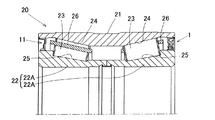
この車輪用軸受20は、互いに複列の転動体23を介して相対回転する外方部材21と内方部材22とを備え、車体に対して車輪を回転自在に支持するようにしたものである。転動体23は円すいころからなり、外方部材21の内周に形成された互いに小径側が隣合う複列の円すい状の転走面24と、これら転走面24にそれぞれ対向して内方部材22の外周に形成された複列の円すい状の転走面25との間に介在する。内方部材22は、2つの軸受内輪22Aを軸方向に並べた分割型内輪からなる。転動体23は各列毎に保持器26で保持されている。ここでは、外方部材21が固定側部材とされ、内方部材22が回転側部材とされる。外方部材21と内方部材22の間の軸受空間の両端は、軸受密封装置1,11によりそれぞれ密封されている。
An embodiment of the present invention will be described with reference to FIGS. This embodiment is applied to a double row tapered roller bearing type wheel bearing classified as a first generation type. In this specification, the side closer to the outer side in the vehicle width direction of the vehicle when attached to the vehicle is referred to as the outboard side, and the side closer to the center of the vehicle is referred to as the inboard side.
The wheel bearing 20 includes an
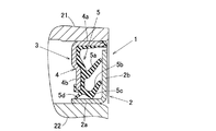
車輪用軸受20のインボード側端に設けられる軸受密封装置1は、図2に示すように、前記内方部材22および外方部材21にそれぞれ取付けられて互いに対向する環状のシール板2および弾性シール部材3からなる。シール板2はスリンガとなる部材であって、内方部材22の外周面に嵌合する円筒部2aと、この円筒部2aの端部から立ち上がる立板部2bとからなる断面L字状の金属製とされる。弾性シール部材3は、環状の芯金4に弾性体5を固着したものである。芯金4は、外方部材21の内周面に嵌合する円筒部4aと、この円筒部4aの端部から立ち下がる立板部4bとを有し、前記シール板2と軸方向に対向する断面逆L字状とされている。弾性体5は、芯金4の内側を覆って設けられたものであり、2枚のサイドリップ5a,5bと、2枚のラジアルリップ5c,5dとを有する。2枚のサイドイップ5a,5bは、互いに芯金4の径方向の内外に並んで配置され、芯金4の立板部4bから斜め外径側へ延びて、それぞれ先端が前記シール板2の立板部2bに接する。サイドリップ5a,5bは外部からの泥水浸入防止用である。1枚のラジアルリップ5cも泥水浸入防止用であり、芯金4の立板部4bの先端からシール板2の立板部2b側へ斜め内径側へ延びて、先端が前記シール板2の円筒部2aに接する。もう1枚のラジアルリップ5dはグリース漏れ防止用であり、芯金4の立板部4bの先端からシール板2の立板部2bと反対側へ斜め内径側へ延びて、先端が前記シール板2の円筒部2aに接する。前記各サイドリップ5a,5bおよびラジアルリップ5c,5dは、具体的には弾性体5における芯金4の立板部4bを覆う覆い部分5eを介して芯金4から延びている。シール板2の内径面から、弾性シール部材3の外径面までの径方向長さである密封装置断面高さHは、9〜15mmとされている。
As shown in FIG. 2, the bearing
このように、上記構成の車輪用軸受20では、その軸受空間のインボード側端に設けられる軸受密封装置1における密封装置断面高さHを9〜15mmとしているので、耐泥水性能を向上させることができる。密封装置断面高さHを9mmより低くすると、上記2枚のサイドリップ5a,5bおよび2枚のラジアルリップ5c,5dを有する構造の軸受密封装置1が成り立たないし、15mmより高くすると、車輪用軸受20の径方向寸法が大きくなって車輪用軸受20の重量増加を招くので好ましくない。すなわち、この車輪用軸受装置20によると、重量増加を招くことなく耐泥水性能を向上させることができる。なお、図1の車輪用軸受20では、軸受空間のインボード側端だけを図2の構造の軸受密封装置1で密封しているが、軸受空間のアウトボード側端も同じ軸受密封装置1で密封するようにしても良い。一般的には、車輪用軸受において、インボード側端は、泥水等がかかり易い箇所となるが、アウトボード側端は泥水等がかかり難いため、アウトボード側端の密封装置11は簡易な構成のもので足りる。
Thus, in the wheel bearing 20 having the above-described configuration, the sealing device cross-sectional height H in the
図3は、前記軸受密封装置1の他の構成例を示す。この構成例では、図2の構成例において、2枚のラジアルリップ5c,5dのうち、シール板2の立板部2b側へ延びる1枚のラジアルリップ5cに、縮径付勢するリング状ばね部材6が設けられている。リング状ばね部材6には、ガータスプリング等が用いられる。その他の構成は、図2の構成例の場合と同様である。図1の車輪用軸受20において、インボード側端の軸受密封装置1を図3の構成例のものに置き換えた例を図6に示す。
FIG. 3 shows another configuration example of the
このように、ラジアルリップ5cに縮径付勢するリング状ばね部材6が設けられた構成では、シール板2の円筒部2aへのラジアルリップ5cの接触が強められると共に、車両への軸受取り付け時の偏芯によるラジアルリップ5cのリップ追従性が増すので、ラジアルリップ5cによる泥水浸入防止効果がさらに高まる。
As described above, in the configuration in which the
図4は、この発明とは異なる提案例に係る軸受密封装置の構成例を示す。この構成例では、図2の構成例において、2枚のサイドリップ5a,5bのうち、内径側のサイドリップ5bを、2枚のラジアルリップ5c,5dのうち、シール板2の立板部2b側へ延びる1枚のラジアルリップ5cの先端から延びて一体のシールリップを構成するように形成している。その他の構成は、図2の構成例の場合と同様である。
FIG. 4 shows a configuration example of a bearing sealing device according to a proposed example different from the present invention . In this configuration example, in the configuration example of FIG. 2, the
このように、内径側のサイドリップ5bを、ラジアルリップ5cの先端から延びて一体のシールリップを構成するように形成した場合には、軸受密封装置1のシールリップ構造を簡略化できるので、密封装置断面高さHを15mm以下に抑えるのが容易となる。
In this way, when the
図5は、この発明とは異なる提案例である軸受密封装置の他の構成例を示す。この構成例では、図4の構成例において、前記サイドリップ5bとラジアルリップ5cとが一体となったシールリップに、縮径付勢するリング状ばね部材6が設けられている。その他の構成は、図4の構成例の場合と同様である。
FIG. 5 shows another configuration example of a bearing sealing device which is a proposed example different from the present invention . In this configuration example, in the configuration example of FIG. 4, a ring-shaped
このように、内径側のサイドリップ5bを、ラジアルリップ5cの先端から延びて一体のシールリップを構成するように形成すると共に、一体のシールリップに縮径付勢するリング状ばね部材6を設けた場合には、軸受密封装置1のシールリップ構造を簡略化できて密封装置断面高さHを15mm以下に抑えることが容易になると共に、シール板2の立板部2bおよび円筒部2aへのサイドリップ5bおよびラジアルリップ5cの接触が強められ、車両への軸受取り付け時の偏芯によるラジアルリップ5cのリップ追従性が増すので、泥水浸入防止効果がさらに高まる。
In this way, the
図7は、車輪用軸受の他の実施形態を示す。この車輪用軸受30は、第1世代型に分類される複列外向きアンギュラ玉軸受型とされている。すなわち、この車輪用軸受30は、図1に示す車輪用軸受20における転動体23をボールに置き換えたものであり、内外の部材22,21間に形成される環状空間の両端が一対の軸受密封装置1,1で密封されている。ここでは、インボード側およびアウトボード側の軸受密封装置1として、図2の構成例のものが用いられている。内方部材22が、2つの軸受内輪22Aを軸方向に並べた分割型内輪からなることも、図1の実施形態の場合と同様である。
FIG. 7 shows another embodiment of the wheel bearing. The
図8は、車輪用軸受のさらに他の実施形態を示す。この車輪用軸受40は、第2世代型に分類される複列外向きアンギュラ玉軸受型であり、外輪回転タイプでかつ従動輪支持用のものである。この車輪用軸受40は、内周に複列の転走面44を有するハブ輪兼用の外方部材41と、これら転走面44にそれぞれ対向する転走面45を有する内方部材42と、これら複列の転走面44,45間に介在する複列の転動体43とを備える。外方部材41は、外周にホイール取付用のハブフランジ41aを有する。このハブフランジ41aには、ブレーキロータを介してホイール(いずれも図示せず)がハブボルト37で取付けられる。内方部材42は各転走面45をそれぞれ有する2つの軸受内輪42A,42Aを軸方向に並べた分割型内輪からなる。内方部材42の内径面には車軸(図示せず)が固定される。転動体43はボールからなり、各列毎に保持器46で保持されている。内外の部材42,41間に形成される環状空間の両端が一対の軸受密封装置1,12で密封されている。インボード側の軸受密封装置1として、図2の構成例のものが用いられている。
FIG. 8 shows still another embodiment of the wheel bearing. The
図9は、車輪用軸受のさらに他の実施形態を示す。この車輪用軸受50は、第2世代型に分類される複列円すいころ軸受型であり、内輪回転タイプでかつ駆動輪支持用のものである。この車輪用軸受50は、内周に複列の転走面54を有する外方部材51と、これら転走面54にそれぞれ対向する転走面55を有する内方部材52と、これら複列の転走面54,55間に介在する複列の転動体53とを備える。転動体53は円すいころからなり、各列毎に保持器56で保持されている。外方部材51は固定側の部材となるものであって、車体の懸架装置を構成するナックル(図示せず)に取付けるフランジ51aを外周に有し、全体が一体の部品とされている。内方部材52は回転側の部材となるものであって、ハブ輪57とその外周に嵌合する一対の分割型の内輪58A,58Bとでなり、これら一対の内輪58A,58Bに各列の転走面55が形成される。ハブ輪57は、外周にホイール取付用のハブフランジ57aを有する。このハブフランジ57aには、ブレーキロータを介してホイール(いずれも図示せず)がハブボルト37で取付けられる。ハブ輪57の軸部57bのインボード側端は加締部57cとされ、この加締部57cが内輪58Bの幅面に押し当てられる。ハブ輪57は中央孔59を有し、この中央孔59にアウトボード側の等速自在継手(図示せず)の外側継手部材が、スプライン嵌合により連結される。内外の部材52,51間に形成される環状空間の両端が、図2の構成例の軸受密封装置1で密封されている。
FIG. 9 shows still another embodiment of the wheel bearing. The
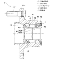
図10は、車輪用軸受のさらに他の実施形態を示す。この車輪用軸受60は、第3世代型に分類される複列外向きアンギュラ玉軸受型であり、内輪回転タイプでかつ駆動輪支持用のものである。この車輪用軸受60は、内周に複列の転走面64を有する外方部材61と、これら転走面64にそれぞれ対向する転走面65を有する内方部材62と、これら複列の転走面64,65間に介在する複列の転動体63とを備える。外方部材61は固定側の部材となるものであって、車体の懸架装置(図示せず)におけるナックルに取付けるフランジ61aを外周に有し、全体が一体の部品とされている。内方部材62は回転側の部材となるものであって、外周にホイール取付用のハブフランジ67aを有するハブ輪67と、このハブ輪67の軸部67bのインボード側端の外周に嵌合した内輪68とでなる。これらハブ輪67および内輪68に前記各列の転走面65が形成されている。転動体63はボールからなり、各列毎に保持器66で保持されている。内外の部材62,61間に形成される環状空間の両端が一対の軸受密封装置1,13で密封されている。インボード側の軸受密封装置1として、図2の構成例のものが用いられている。
FIG. 10 shows still another embodiment of the wheel bearing. This wheel bearing 60 is a double-row outward angular contact ball bearing type classified as a third generation type, and is an inner ring rotating type and for driving wheel support. The
この車輪用軸受60の車両への組付けにおいては、等速自在継手の外側継手部材16のステム部16aをハブ輪67の貫通孔17に挿通して、ステム部16aの外周面と貫通孔17の内周面とをスプライン嵌合させ、ステム部16aの先端に螺合するナット18の締め付けにより、前記外側継手部材16を内方部材62に結合する。このとき、外側継手部材16に設けられたアウトボード側の断面16bが、内輪68のインボード側に向く端面68aに押し付けられ、外側継手部材16とナット18とで内方部材62が幅締めされる。ホイール取付用のハブフランジ67aはハブ輪67のアウトボード側端に位置しており、このハブフランジ67aにブレーキロータを介してホイール(いずれも図示せず)がハブボルト37で取付けられる。
In assembling the wheel bearing 60 to the vehicle, the
図11は、車輪用軸受のさらに他の実施形態を示す。この車輪用軸受70は、第4世代型に分類される複列外向きアンギュラ玉軸受型であり、内輪回転タイプでかつ駆動輪支持用のものである。この車輪用軸受70は、内周に複列の転走面74を有する外方部材71と、これら転走面74にそれぞれ対向する転走面75を有する内方部材72と、これら複列の転走面74,75間に介在する複列の転動体73とを備える。転動体73はボールからなり、各列毎に保持器76で保持されている。内外の部材72,71間に形成される環状空間の両端が一対の軸受密封装置1,14で密封されている。インボード側の軸受密封装置1として、図2の構成例のものが用いられている。
FIG. 11 shows still another embodiment of the wheel bearing. This wheel bearing 70 is a double-row outward angular contact ball bearing type classified as a fourth generation type, and is an inner ring rotating type and supporting a driving wheel. The
外方部材71は固定側の部材となるものであって、車体の懸架装置(図示せず)におけるナックルに取付けるフランジ71aを外周に有し、全体が一体の部品とされている。内方部材72は回転側の部材となるものであって、軸部77bの外周にホイール取付用のハブフランジ77aを有するハブ輪77と、このハブ輪77の中央孔79にステム部78aが挿入されて嵌合する等速自在継手90の外側継手部材78とでなる。これらハブ輪77および外側継手部材78に前記各列の転走面75が形成されている。ハブ輪77のハブフランジ77aには、ブレーキロータを介してホイール(いずれも図示せず)がハブボルト37で取付けられる。等速自在継手90は、外側継手部材78のカップ状部分78bの球形内面に形成された複数の軸方向溝95と、内側継手部材91の球形外面に設けられた複数の軸方向溝92内との間に、トルク伝達ボール93をそれぞれ介在させ、トルク伝達ボール93を保持する保持器94を設けたものである。
The
1…軸受密封装置
2…シール板
2a…円筒部
2b…立板部
3…弾性シール部材
4…芯金
4a…円筒部
4b…立板部
5…弾性体
5a,5b…サイドリップ
5c,5d…ラジアルリップ
6…リング状ばね部材
20〜70…車輪用軸受
21,41,51,61,71…外方部材
22,42,52,62,72…内方部材
23,43,53,63,73…転動体
41a,57a,67a,77a…ハブフランジ
51a,61a,71a…ホイール取付用のフランジ
57,67,77…ハブ輪
57b,67b,77b…ハブ輪の軸部
24,44,54,64,74…外方部材の転走面
25,45,55,65,75…内方部材の転走面
16,78…等速自在継手の外側継手部材
16a,78a…外側継手部材のステム部
DESCRIPTION OF
Claims (9)
前記軸受空間におけるインボード側端およびアウトボード側端のいずれか一方または両方に設けられる軸受密封装置を、前記内方部材および外方部材にそれぞれ取付けられて互いに対向する環状のシール板および弾性シール部材からなるものとし、
前記シール板は、前記内方部材の外周に嵌合する円筒部およびこの円筒部の端部から立ち上がる立板部からなる断面L字状の金属製とされ、
前記弾性シール部材は、環状の芯金およびこの芯金に固着された弾性体からなり、
前記芯金は前記外方部材の内周面に嵌合する円筒部およびこの円筒部の端部から立ち下がる立板部を有し前記シール板と対向する断面L字状とされ、
前記弾性体は、互いに前記芯金の径方向の内外に並びそれぞれ先端が前記シール板の立板部に接する2枚のサイドリップと、軸方向に並び前記シール板の外周面に先端が接触または近接する2枚のラジアルリップとを有し、
前記2枚のサイドリップおよび前記2枚のラジアルリップは、いずれも、前記弾性体における前記芯金の前記立板部を覆う覆い部分からそれぞれ独立して延び、
前記2枚のサイドリップは、前記芯金の前記立板部から前記覆い部分を介して斜め外径側へ延び、
前記2枚のラジアルリップは、前記芯金の前記立板部の先端から前記覆い部分を介して延び、これら2枚のラジアルリップのうち、前記シール板の立板部側のラジアルリップは前記シール板の立板部側へ斜め内径側へ延びる、
ことを特徴とする車輪用軸受。 It has an outer member and an inner member that rotate relative to each other via double row rolling elements, and has bearing sealing devices at both ends of the bearing space between the outer member and the inner member. In the wheel bearing that supports the wheel,
An annular seal plate and an elastic seal, which are respectively attached to the inner member and the outer member and face each other, with a bearing sealing device provided at one or both of the inboard side end and the outboard side end in the bearing space. It shall consist of members,
The seal plate is made of a metal having an L-shaped cross section composed of a cylindrical portion fitted to the outer periphery of the inner member and a standing plate portion rising from an end portion of the cylindrical portion,
The elastic seal member is composed of an annular cored bar and an elastic body fixed to the cored bar,
The cored bar has a cylindrical portion that fits to the inner peripheral surface of the outer member and a standing plate portion that falls from an end portion of the cylindrical portion, and has an L-shaped cross section facing the seal plate,
The elastic bodies are aligned with each other in the radial direction of the cored bar, the two side lips whose tips are in contact with the standing plate portion of the seal plate, and the tips are in contact with the outer peripheral surface of the seal plate aligned in the axial direction. have a and two radial lip in close proximity,
Each of the two side lips and the two radial lips extends independently from a covering portion that covers the standing plate portion of the cored bar in the elastic body,
The two side lips extend from the standing plate portion of the core metal to the oblique outer diameter side through the covering portion,
The two radial lips extend from the tip of the vertical plate portion of the core metal through the cover portion, and the radial lip on the vertical plate portion side of the seal plate is the seal lip of the two radial lips. Extends diagonally to the inner diameter side toward the vertical plate part side of the plate,
Wheel bearing which is characterized a call.
Priority Applications (6)
| Application Number | Priority Date | Filing Date | Title |
|---|---|---|---|
| JP2007291454A JP5328136B2 (en) | 2007-11-09 | 2007-11-09 | Wheel bearing |
| CN2008801151459A CN101855464B (en) | 2007-11-09 | 2008-11-04 | Bearing sealing device, and bearing adapted for use in wheel |
| CN201210557356.6A CN103047295B (en) | 2007-11-09 | 2008-11-04 | Bearing for wheel |
| US12/734,556 US8356942B2 (en) | 2007-11-09 | 2008-11-04 | Sealing device for bearing assembly and wheel support bearing assembly therewith |
| DE112008002994T DE112008002994T5 (en) | 2007-11-09 | 2008-11-04 | Sealing device for bearing assembly and Radstützlageranordnung with this |
| PCT/JP2008/003158 WO2009060584A1 (en) | 2007-11-09 | 2008-11-04 | Bearing sealing device, and bearing adapted for use in wheel and using the bearing sealing device |
Applications Claiming Priority (1)
| Application Number | Priority Date | Filing Date | Title |
|---|---|---|---|
| JP2007291454A JP5328136B2 (en) | 2007-11-09 | 2007-11-09 | Wheel bearing |
Related Child Applications (1)
| Application Number | Title | Priority Date | Filing Date |
|---|---|---|---|
| JP2013027365A Division JP5715171B2 (en) | 2013-02-15 | 2013-02-15 | Bearing sealing device and wheel bearing |
Publications (3)
| Publication Number | Publication Date |
|---|---|
| JP2009115273A JP2009115273A (en) | 2009-05-28 |
| JP2009115273A5 JP2009115273A5 (en) | 2011-07-21 |
| JP5328136B2 true JP5328136B2 (en) | 2013-10-30 |
Family
ID=40782624
Family Applications (1)
| Application Number | Title | Priority Date | Filing Date |
|---|---|---|---|
| JP2007291454A Active JP5328136B2 (en) | 2007-11-09 | 2007-11-09 | Wheel bearing |
Country Status (1)
| Country | Link |
|---|---|
| JP (1) | JP5328136B2 (en) |
Families Citing this family (5)
| Publication number | Priority date | Publication date | Assignee | Title |
|---|---|---|---|---|
| JP2011088513A (en) * | 2009-10-21 | 2011-05-06 | Ntn Corp | Bearing seal for wheels and bearing device for wheels equipped with the same |
| JP5964120B2 (en) | 2012-04-13 | 2016-08-03 | Ntn株式会社 | Wheel bearing sealing device |
| JP2015161366A (en) * | 2014-02-27 | 2015-09-07 | 日本精工株式会社 | Rolling bearing with seal |
| KR101857192B1 (en) * | 2016-08-17 | 2018-05-11 | 주식회사 일진글로벌 | Sealing apparatus of wheel bearing |
| JP7274269B2 (en) | 2018-07-31 | 2023-05-16 | Ntn株式会社 | Wheel bearing device provided with seal member and seal member |
Family Cites Families (5)
| Publication number | Priority date | Publication date | Assignee | Title |
|---|---|---|---|---|
| JPH0730988Y2 (en) * | 1985-10-22 | 1995-07-19 | エヌティエヌ株式会社 | Bearing seal device |
| US5201529A (en) * | 1990-02-16 | 1993-04-13 | Nok Corporation | Sealing device |
| JPH0493571U (en) * | 1990-12-28 | 1992-08-13 | ||
| JP2586741Y2 (en) * | 1992-07-30 | 1998-12-09 | エヌティエヌ株式会社 | Bearing sealing device |
| JP2601238Y2 (en) * | 1993-11-30 | 1999-11-15 | エヌティエヌ株式会社 | Sealing device for wheel bearings |
-
2007
- 2007-11-09 JP JP2007291454A patent/JP5328136B2/en active Active
Also Published As
| Publication number | Publication date |
|---|---|
| JP2009115273A (en) | 2009-05-28 |
Similar Documents
| Publication | Publication Date | Title |
|---|---|---|
| JP5184820B2 (en) | Wheel bearing device | |
| JP2008298106A (en) | Wheel bearing device | |
| JP2012056411A (en) | Wheel bearing device | |
| JP2010053893A (en) | Wheel-bearing device | |
| JP5328136B2 (en) | Wheel bearing | |
| JP2011007272A (en) | Wheel bearing device | |
| WO2014091883A1 (en) | Rolling bearing | |
| JP2010032013A (en) | Bearing device for wheel | |
| JP2011088513A (en) | Bearing seal for wheels and bearing device for wheels equipped with the same | |
| JP5414964B2 (en) | Wheel bearing device | |
| JPH0734226U (en) | Sealing device for wheel bearings | |
| WO2007138738A1 (en) | Bearing device for wheel | |
| JP2009127790A (en) | Bearing sealing device and bearing for wheel using the same | |
| JP2007100844A (en) | Bearing device for wheel | |
| JP2016130113A (en) | Semi-floating type wheel support device | |
| JP5314877B2 (en) | Wheel bearing device | |
| JP5988738B2 (en) | Wheel bearing device | |
| JP5715171B2 (en) | Bearing sealing device and wheel bearing | |
| JP2005330987A (en) | Sealed rolling bearing and seal | |
| JP2012082912A (en) | Rolling bearing device for wheel | |
| JP2007120771A (en) | Bearing device for wheel | |
| JP2007162828A (en) | Wheel bearing device and axle module equipped therewith | |
| JP2007113759A (en) | Hub unit bearing | |
| JP2019128018A (en) | Wheel bearing device | |
| JP2015117727A (en) | Hub unit |
Legal Events
| Date | Code | Title | Description |
|---|---|---|---|
| A621 | Written request for application examination |
Free format text: JAPANESE INTERMEDIATE CODE: A621 Effective date: 20101028 |
|
| A521 | Request for written amendment filed |
Free format text: JAPANESE INTERMEDIATE CODE: A523 Effective date: 20110603 |
|
| A131 | Notification of reasons for refusal |
Free format text: JAPANESE INTERMEDIATE CODE: A131 Effective date: 20121218 |
|
| A521 | Request for written amendment filed |
Free format text: JAPANESE INTERMEDIATE CODE: A523 Effective date: 20130215 |
|
| TRDD | Decision of grant or rejection written | ||
| A01 | Written decision to grant a patent or to grant a registration (utility model) |
Free format text: JAPANESE INTERMEDIATE CODE: A01 Effective date: 20130709 |
|
| A61 | First payment of annual fees (during grant procedure) |
Free format text: JAPANESE INTERMEDIATE CODE: A61 Effective date: 20130723 |
|
| R150 | Certificate of patent or registration of utility model |
Ref document number: 5328136 Country of ref document: JP Free format text: JAPANESE INTERMEDIATE CODE: R150 Free format text: JAPANESE INTERMEDIATE CODE: R150 |
|
| R250 | Receipt of annual fees |
Free format text: JAPANESE INTERMEDIATE CODE: R250 |
|
| R250 | Receipt of annual fees |
Free format text: JAPANESE INTERMEDIATE CODE: R250 |
|
| R250 | Receipt of annual fees |
Free format text: JAPANESE INTERMEDIATE CODE: R250 |
|
| R250 | Receipt of annual fees |
Free format text: JAPANESE INTERMEDIATE CODE: R250 |
|
| R250 | Receipt of annual fees |
Free format text: JAPANESE INTERMEDIATE CODE: R250 |
|
| R250 | Receipt of annual fees |
Free format text: JAPANESE INTERMEDIATE CODE: R250 |
|
| R250 | Receipt of annual fees |
Free format text: JAPANESE INTERMEDIATE CODE: R250 |
|
| R250 | Receipt of annual fees |
Free format text: JAPANESE INTERMEDIATE CODE: R250 |