EP2402161B1 - Method of liquid discharge, liquid discharge head - Google Patents
Method of liquid discharge, liquid discharge head Download PDFInfo
- Publication number
- EP2402161B1 EP2402161B1 EP11181409.1A EP11181409A EP2402161B1 EP 2402161 B1 EP2402161 B1 EP 2402161B1 EP 11181409 A EP11181409 A EP 11181409A EP 2402161 B1 EP2402161 B1 EP 2402161B1
- Authority
- EP
- European Patent Office
- Prior art keywords
- liquid
- discharge port
- discharge
- projections
- projection
- Prior art date
- Legal status (The legal status is an assumption and is not a legal conclusion. Google has not performed a legal analysis and makes no representation as to the accuracy of the status listed.)
- Not-in-force
Links
- 239000007788 liquid Substances 0.000 title claims description 396
- 238000000034 method Methods 0.000 title claims description 38
- 239000012530 fluid Substances 0.000 claims description 35
- 238000007599 discharging Methods 0.000 claims description 13
- 238000000926 separation method Methods 0.000 description 34
- 238000010586 diagram Methods 0.000 description 27
- 230000008569 process Effects 0.000 description 23
- 230000005499 meniscus Effects 0.000 description 21
- 230000000694 effects Effects 0.000 description 12
- 230000009467 reduction Effects 0.000 description 10
- 239000003595 mist Substances 0.000 description 9
- 239000000758 substrate Substances 0.000 description 9
- 230000015572 biosynthetic process Effects 0.000 description 8
- VZSRBBMJRBPUNF-UHFFFAOYSA-N 2-(2,3-dihydro-1H-inden-2-ylamino)-N-[3-oxo-3-(2,4,6,7-tetrahydrotriazolo[4,5-c]pyridin-5-yl)propyl]pyrimidine-5-carboxamide Chemical compound C1C(CC2=CC=CC=C12)NC1=NC=C(C=N1)C(=O)NCCC(N1CC2=C(CC1)NN=N2)=O VZSRBBMJRBPUNF-UHFFFAOYSA-N 0.000 description 7
- 230000008034 disappearance Effects 0.000 description 7
- 238000005562 fading Methods 0.000 description 7
- 239000012298 atmosphere Substances 0.000 description 6
- 239000002245 particle Substances 0.000 description 6
- 230000007246 mechanism Effects 0.000 description 5
- 239000011347 resin Substances 0.000 description 5
- 229920005989 resin Polymers 0.000 description 5
- 238000004088 simulation Methods 0.000 description 5
- AFCARXCZXQIEQB-UHFFFAOYSA-N N-[3-oxo-3-(2,4,6,7-tetrahydrotriazolo[4,5-c]pyridin-5-yl)propyl]-2-[[3-(trifluoromethoxy)phenyl]methylamino]pyrimidine-5-carboxamide Chemical compound O=C(CCNC(=O)C=1C=NC(=NC=1)NCC1=CC(=CC=C1)OC(F)(F)F)N1CC2=C(CC1)NN=N2 AFCARXCZXQIEQB-UHFFFAOYSA-N 0.000 description 4
- XUIMIQQOPSSXEZ-UHFFFAOYSA-N Silicon Chemical compound [Si] XUIMIQQOPSSXEZ-UHFFFAOYSA-N 0.000 description 4
- 230000008901 benefit Effects 0.000 description 4
- 238000004519 manufacturing process Methods 0.000 description 4
- 229910052710 silicon Inorganic materials 0.000 description 4
- 239000010703 silicon Substances 0.000 description 4
- LDXJRKWFNNFDSA-UHFFFAOYSA-N 2-(2,4,6,7-tetrahydrotriazolo[4,5-c]pyridin-5-yl)-1-[4-[2-[[3-(trifluoromethoxy)phenyl]methylamino]pyrimidin-5-yl]piperazin-1-yl]ethanone Chemical compound C1CN(CC2=NNN=C21)CC(=O)N3CCN(CC3)C4=CN=C(N=C4)NCC5=CC(=CC=C5)OC(F)(F)F LDXJRKWFNNFDSA-UHFFFAOYSA-N 0.000 description 3
- 238000009835 boiling Methods 0.000 description 3
- 238000012545 processing Methods 0.000 description 3
- 238000011084 recovery Methods 0.000 description 3
- HMUNWXXNJPVALC-UHFFFAOYSA-N 1-[4-[2-(2,3-dihydro-1H-inden-2-ylamino)pyrimidin-5-yl]piperazin-1-yl]-2-(2,4,6,7-tetrahydrotriazolo[4,5-c]pyridin-5-yl)ethanone Chemical compound C1C(CC2=CC=CC=C12)NC1=NC=C(C=N1)N1CCN(CC1)C(CN1CC2=C(CC1)NN=N2)=O HMUNWXXNJPVALC-UHFFFAOYSA-N 0.000 description 2
- 239000000919 ceramic Substances 0.000 description 2
- 230000000593 degrading effect Effects 0.000 description 2
- 238000013461 design Methods 0.000 description 2
- 238000005530 etching Methods 0.000 description 2
- 239000011521 glass Substances 0.000 description 2
- 239000000463 material Substances 0.000 description 2
- 230000000704 physical effect Effects 0.000 description 2
- 230000002940 repellent Effects 0.000 description 2
- 239000005871 repellent Substances 0.000 description 2
- XLYOFNOQVPJJNP-UHFFFAOYSA-N water Substances O XLYOFNOQVPJJNP-UHFFFAOYSA-N 0.000 description 2
- 241001272720 Medialuna californiensis Species 0.000 description 1
- 238000005452 bending Methods 0.000 description 1
- 230000015556 catabolic process Effects 0.000 description 1
- 230000008859 change Effects 0.000 description 1
- 239000003795 chemical substances by application Substances 0.000 description 1
- 239000003086 colorant Substances 0.000 description 1
- 239000013078 crystal Substances 0.000 description 1
- 238000006731 degradation reaction Methods 0.000 description 1
- 230000001419 dependent effect Effects 0.000 description 1
- 230000006866 deterioration Effects 0.000 description 1
- 238000011161 development Methods 0.000 description 1
- 238000011156 evaluation Methods 0.000 description 1
- 239000004744 fabric Substances 0.000 description 1
- 230000005484 gravity Effects 0.000 description 1
- 239000010985 leather Substances 0.000 description 1
- 238000001459 lithography Methods 0.000 description 1
- 238000005259 measurement Methods 0.000 description 1
- 239000002184 metal Substances 0.000 description 1
- 238000012986 modification Methods 0.000 description 1
- 230000004048 modification Effects 0.000 description 1
- 238000000206 photolithography Methods 0.000 description 1
- 239000004033 plastic Substances 0.000 description 1
- 239000002985 plastic film Substances 0.000 description 1
- 229920006255 plastic film Polymers 0.000 description 1
- 230000000717 retained effect Effects 0.000 description 1
- 239000002904 solvent Substances 0.000 description 1
- 238000004528 spin coating Methods 0.000 description 1
- 239000002023 wood Substances 0.000 description 1
Images


Classifications
-
- B—PERFORMING OPERATIONS; TRANSPORTING
- B41—PRINTING; LINING MACHINES; TYPEWRITERS; STAMPS
- B41J—TYPEWRITERS; SELECTIVE PRINTING MECHANISMS, i.e. MECHANISMS PRINTING OTHERWISE THAN FROM A FORME; CORRECTION OF TYPOGRAPHICAL ERRORS
- B41J2/00—Typewriters or selective printing mechanisms characterised by the printing or marking process for which they are designed
- B41J2/005—Typewriters or selective printing mechanisms characterised by the printing or marking process for which they are designed characterised by bringing liquid or particles selectively into contact with a printing material
- B41J2/01—Ink jet
- B41J2/135—Nozzles
- B41J2/14—Structure thereof only for on-demand ink jet heads
- B41J2/14016—Structure of bubble jet print heads
- B41J2/14032—Structure of the pressure chamber
- B41J2/1404—Geometrical characteristics
-
- B—PERFORMING OPERATIONS; TRANSPORTING
- B41—PRINTING; LINING MACHINES; TYPEWRITERS; STAMPS
- B41J—TYPEWRITERS; SELECTIVE PRINTING MECHANISMS, i.e. MECHANISMS PRINTING OTHERWISE THAN FROM A FORME; CORRECTION OF TYPOGRAPHICAL ERRORS
- B41J2/00—Typewriters or selective printing mechanisms characterised by the printing or marking process for which they are designed
- B41J2/005—Typewriters or selective printing mechanisms characterised by the printing or marking process for which they are designed characterised by bringing liquid or particles selectively into contact with a printing material
- B41J2/01—Ink jet
- B41J2/015—Ink jet characterised by the jet generation process
- B41J2/04—Ink jet characterised by the jet generation process generating single droplets or particles on demand
- B41J2/045—Ink jet characterised by the jet generation process generating single droplets or particles on demand by pressure, e.g. electromechanical transducers
- B41J2/04501—Control methods or devices therefor, e.g. driver circuits, control circuits
- B41J2/04573—Timing; Delays
-
- B—PERFORMING OPERATIONS; TRANSPORTING
- B41—PRINTING; LINING MACHINES; TYPEWRITERS; STAMPS
- B41J—TYPEWRITERS; SELECTIVE PRINTING MECHANISMS, i.e. MECHANISMS PRINTING OTHERWISE THAN FROM A FORME; CORRECTION OF TYPOGRAPHICAL ERRORS
- B41J2/00—Typewriters or selective printing mechanisms characterised by the printing or marking process for which they are designed
- B41J2/005—Typewriters or selective printing mechanisms characterised by the printing or marking process for which they are designed characterised by bringing liquid or particles selectively into contact with a printing material
- B41J2/01—Ink jet
- B41J2/135—Nozzles
- B41J2/14—Structure thereof only for on-demand ink jet heads
- B41J2/14016—Structure of bubble jet print heads
- B41J2/14024—Assembling head parts
-
- B—PERFORMING OPERATIONS; TRANSPORTING
- B41—PRINTING; LINING MACHINES; TYPEWRITERS; STAMPS
- B41J—TYPEWRITERS; SELECTIVE PRINTING MECHANISMS, i.e. MECHANISMS PRINTING OTHERWISE THAN FROM A FORME; CORRECTION OF TYPOGRAPHICAL ERRORS
- B41J2/00—Typewriters or selective printing mechanisms characterised by the printing or marking process for which they are designed
- B41J2/005—Typewriters or selective printing mechanisms characterised by the printing or marking process for which they are designed characterised by bringing liquid or particles selectively into contact with a printing material
- B41J2/01—Ink jet
- B41J2/135—Nozzles
- B41J2/14—Structure thereof only for on-demand ink jet heads
- B41J2/1433—Structure of nozzle plates
-
- B—PERFORMING OPERATIONS; TRANSPORTING
- B41—PRINTING; LINING MACHINES; TYPEWRITERS; STAMPS
- B41J—TYPEWRITERS; SELECTIVE PRINTING MECHANISMS, i.e. MECHANISMS PRINTING OTHERWISE THAN FROM A FORME; CORRECTION OF TYPOGRAPHICAL ERRORS
- B41J2/00—Typewriters or selective printing mechanisms characterised by the printing or marking process for which they are designed
- B41J2/005—Typewriters or selective printing mechanisms characterised by the printing or marking process for which they are designed characterised by bringing liquid or particles selectively into contact with a printing material
- B41J2/01—Ink jet
- B41J2/135—Nozzles
- B41J2/145—Arrangement thereof
-
- B—PERFORMING OPERATIONS; TRANSPORTING
- B41—PRINTING; LINING MACHINES; TYPEWRITERS; STAMPS
- B41J—TYPEWRITERS; SELECTIVE PRINTING MECHANISMS, i.e. MECHANISMS PRINTING OTHERWISE THAN FROM A FORME; CORRECTION OF TYPOGRAPHICAL ERRORS
- B41J2/00—Typewriters or selective printing mechanisms characterised by the printing or marking process for which they are designed
- B41J2/005—Typewriters or selective printing mechanisms characterised by the printing or marking process for which they are designed characterised by bringing liquid or particles selectively into contact with a printing material
- B41J2/01—Ink jet
- B41J2/135—Nozzles
- B41J2/16—Production of nozzles
- B41J2/1601—Production of bubble jet print heads
- B41J2/1603—Production of bubble jet print heads of the front shooter type
-
- B—PERFORMING OPERATIONS; TRANSPORTING
- B41—PRINTING; LINING MACHINES; TYPEWRITERS; STAMPS
- B41J—TYPEWRITERS; SELECTIVE PRINTING MECHANISMS, i.e. MECHANISMS PRINTING OTHERWISE THAN FROM A FORME; CORRECTION OF TYPOGRAPHICAL ERRORS
- B41J2/00—Typewriters or selective printing mechanisms characterised by the printing or marking process for which they are designed
- B41J2/005—Typewriters or selective printing mechanisms characterised by the printing or marking process for which they are designed characterised by bringing liquid or particles selectively into contact with a printing material
- B41J2/01—Ink jet
- B41J2/135—Nozzles
- B41J2/14—Structure thereof only for on-demand ink jet heads
- B41J2002/14387—Front shooter
-
- B—PERFORMING OPERATIONS; TRANSPORTING
- B41—PRINTING; LINING MACHINES; TYPEWRITERS; STAMPS
- B41J—TYPEWRITERS; SELECTIVE PRINTING MECHANISMS, i.e. MECHANISMS PRINTING OTHERWISE THAN FROM A FORME; CORRECTION OF TYPOGRAPHICAL ERRORS
- B41J2/00—Typewriters or selective printing mechanisms characterised by the printing or marking process for which they are designed
- B41J2/005—Typewriters or selective printing mechanisms characterised by the printing or marking process for which they are designed characterised by bringing liquid or particles selectively into contact with a printing material
- B41J2/01—Ink jet
- B41J2/135—Nozzles
- B41J2/14—Structure thereof only for on-demand ink jet heads
- B41J2002/14475—Structure thereof only for on-demand ink jet heads characterised by nozzle shapes or number of orifices per chamber
Definitions
- the present invention relates to a liquid discharge head that performs recording by discharging liquid droplets onto a medium.
- a liquid discharge system (ink jet recording system)
- a discharge energy generating element used for discharging liquid droplets
- a method that uses a heat generating element is available.
- FIG. 10 is a schematic diagram showing a general discharge process, for a bubble jet (BJ) discharge system, that employs a conventional ink jet head for preventing bubbles from communicating with the atmosphere.
- BJ bubble jet
- FIG. 10 a liquid portion that is externally ejected through an orifice plate, wherein a discharge port is formed, is called discharged liquid, and liquid remaining within the discharge port is called flow path liquid, in order to distinguish between these liquid portions.
- a film boiling phenomenon is produced at the surface of the heater by electrifying the heater ((b) of FIG. 10 ).
- liquid is forced outward, from the surface of the orifice plate in which the discharge port is formed ((c) of FIG. 10 ).
- the liquid near the heater is moved, as a bubble, away from the heater. Since the interface status of the bubble and the liquid is altered by this movement of the liquid, gas near the heater behaves as though it were growing.
- the state, at this time, is insulated from the heat produced by the heater, and heat is not transmitted to the bubble, so that as the bubble grows, the pressure of the gas is reduced. Furthermore, the inertial force also increases the quantity of the liquid that is discharged. When the inertial force of this liquid finally becomes proportional to a recovery force that accompanies the reduction in the pressure of the gas, growth of the bubble is halted, and a maximum bubble state is achieved ((d) of FIG. 10 ). Since the gas portion in the maximum bubble state is under a pressure sufficiently lower than the atmosphere, thereafter, the bubble begins to disappear, and the liquid in the surrounding area is rapidly drawn into the space once occupied by the bubble ((e) of FIG. 10 ).
- the discharged liquid which can no longer maintain the liquid pillar state, is separated by breaking away, countering the viscosity of the liquid, and becomes a separate liquid droplet ((g) of FIG. 10 ).
- a tiny mist is formed.
- the flying liquid droplet is further separated, forming a main droplet and a sub-droplet (a satellite), in accordance with a velocity difference between the two and the surface tension of the liquid ((h) of FIG. 10 ). Since the satellite is flying to the rear of the main droplet, when it is attached to the paper surface the landing position is shifted away from that of the main droplet. This results in the degradation of the image quality.
- FIG. 12 is a schematic diagram showing a general discharge process performed by a bubble through jet (BTJ) discharge system, employing a conventional ink jet head, whereby bubbles communicate with the atmosphere.
- the height of a flow path is formed lower than that of the BJ discharge system in FIG. 10 .
- An explanation will not be given for the same portion as that for the BJ discharge system in FIG. 10 . While referring to a bubble disappearance process ((e) to (g) of FIG. 12 ), the way in which a meniscus is pulled inside a discharge port differs between a location at the front, in an ink flow path, and at the rear, in the ink flow path, so that the meniscus becomes asymmetrical ((f) of FIG. 12 ).
- JP-A-10-235874 is provided on the assumption that a size larger than the discharge port used for a high image quality head, such as a photographic output head, is used and that the size of a liquid droplet that is to be discharged is also large.
- a liquid droplet separation mechanism is basically unchanged from the conventional one, and the value that can be gained by cutting the tail (the liquid droplet length) is at most about 5 ⁇ m, although this depends on the discharge velocity.
- the present inventors considered that, in order to further shorten the length of a tail, for the reduction of a satellite, the time for the separation of the discharged liquid should be adequately advanced. That is, during a period wherein a discharged liquid, externally stretched outward from a discharge port, is separating from a liquid inside the discharge port, the head of the discharged liquid continues forward. Thus, the earlier the timing at which the discharged liquid separates from the liquid in the discharge port, the shorter the tail of a flying liquid droplet becomes. From this viewpoint, it is preferable that the separation timing for the discharged liquid be moved forward, up to the middle of the bubble disappearance process.
- EP 0 865 922 A2 shows a liquid discharge method and a liquid discharge head according to the prior art, in which lateral curve projections defining hourglass lateral side walls correspond to projections and upper and lower side walls of an hourglass orifice define an outer edge of the hourglass orifice defining a discharge port.
- the area between said side walls of the hourglass orifice defines a larger area than that defining half-moon shaped areas at upper and lower positions of the hourglass orifice so that the area between the projections having a larger fluid resistance than both areas at the upper and lower positions of the hourglass orifice.
- the object of the present invention is achieved by a liquid discharge method having the features of claim 1 and by a liquid discharge head having the features of claim 2.
- a projection is convexly shaped.
- a liquid discharge head wherein a liquid is discharged through a discharge port by applying energy to the liquid from an energy generating element, is arranged in that the discharge port includes, in a cross section of the discharge port, related to a liquid discharge direction, equal to or greater than three convex projections that have convex forms inside the discharge port; and 1.6 ⁇ (x 2 /x 1 ) > 0 is satisfied when x 1 denotes the lengths of the projections related to a direction in which the projections are convexly formed, and x 2 denotes the widths of the roots of the projections related to a widthwise direction of the projections.
- a liquid discharge head wherein a liquid is discharged through a discharge port by applying energy to the liquid from an energy generating element, is arranged in that the discharge port includes, in a cross section of the discharge port, related to a liquid discharge direction, equal to or smaller than two projections that are convexly formed inside the projections; M ⁇ (L - a)/2 > H is established when, in the cross section of the discharge port, related to the liquid discharge direction, H denotes distances from the distal ends of the projections to an outer edge of the discharge port in a direction in which the projections are convexly formed, L denotes the maximum diameter of the discharge port, a denotes a half-width of the projections, and M denotes the minimum diameter of a virtual outer edge of the discharge port; and distal ends of the projections in the cross section of the discharge port have a shape having a curvature, or a shape having a linear portion perpendicular to a direction in which the projections are convexly
- a liquid discharge method whereby a liquid is discharged from a discharge port by applying energy to the liquid from an energy generating element, includes: driving a liquid through a discharge port, which includes, in a cross section of the discharge port, related to a liquid discharge direction, a first area and a plurality of second areas, fluid resistances of which are lower than the first area, so that a pillar-shaped liquid is stretched externally from the discharge port; holding, in the first area, a liquid surface that is connected to the pillar-shaped liquid stretched outside the discharge port, and at the same time, pulling a liquid in the discharge port in a direction opposite to the direction; and while holding the liquid surface in the first area, separating the pillar-shaped liquid, stretched outside the discharge port, from the liquid surface in the first area, and discharging the liquid from the discharge port.
- the timing at which a discharged liquid, stretched outside the discharge port, is to be separated from a liquid that remains in the discharge port can be considerably advanced, and a greater reduction in satellites and mists that deteriorate the image quality is enabled.
- “recording” defines formation of meaningful information, such as drawings. Additionally, “recording” includes general formation of an image, a design, a pattern, etc., on a recording medium, regardless of whether meaningful or meaningless, and regardless of whether information is visualized so as to be visually perceived. Moreover, “recording” also includes a case of processing a medium by applying the liquid to the medium. Further, a “recording medium” represents not only paper used by a common recording apparatus, but also widely represents a medium that can accept ink, such as cloth, plastic film, a metallic plate, glass, ceramics, wood or leather. Furthermore, “ink” or a “liquid” represents a material that is to be applied to a recording medium to form images, designs, patterns, etc.
- such a liquid is also included that is employed as a treatment agent to process a recording medium, or to coagulate a liquid applied to a recording medium or to prevent the dissolving of the liquid.
- a "fluid resistance" indicates ease of movement of a liquid, and for example, since a liquid is not easily moved within a narrow portion, the fluid resistance is increased, and within a broad portion, since the liquid is easily moved, the fluid resistance is lowered. It is assumed that terms, such as parallel, perpendicular and linear, used in this specification are regarded while a range that is about the equivalent of a manufacturing error is included.
- FIG. 7 is a schematic perspective view showing a liquid discharge head for which the present invention is applicable, and the essential portion of an example liquid discharge recording apparatus (an ink jet printer) that serves as a liquid discharge apparatus that employs this head.
- an example liquid discharge recording apparatus an ink jet printer
- the liquid discharge recording apparatus includes, in a casing 1008, a conveying unit 1030 that intermittently conveys a sheet 1028, which is a recording medium, in a direction indicated by an arrow P.
- the liquid discharge recording apparatus includes: a recording unit 1010, which moves parallel to a direction S that is perpendicular to a direction P in which the sheet 1028 is conveyed, and for which a liquid discharge head is provided; and a movement driver 1006, which serves as driving means for reciprocating the recording unit 1010.
- the conveying unit 1030 includes: a pair of roller units 1022a and 1022b and a pair of roller units 1024a and 1024b, which are arranged parallel to and opposite each other; and a driver 1020 which drives these roller units.
- the driver 1020 When the driver 1020 is operated, the sheet 1028 is gripped by the roller units 1022a and 1022b and the roller units 1024a and 1024b, and is intermittently conveyed in the direction P.
- the movement driver 1006 includes a belt 1016 and a motor 1018.
- the belt 1016 is wound around pulleys 1026a and 1026b which are fitted on rotary shafts at a predetermined interval, so that they are opposite each other and is positioned parallel to the roller units 1022a and 1022b.
- the motor 1018 moves, in the forward direction and in the reverse direction, the belt 1016 that is coupled with a carriage member 1010a of the recording unit 1010.
- the carriage member 1010a When the motor 1018 is operated and the belt 1016 is rotated in a direction indicated by an arrow R, the carriage member 1010a is moved, in the direction indicated by an arrow S, at a predetermined distance. Further, when the belt 1016 is moved opposite to the direction indicated by the arrow R, the carriage member 1010a is moved, opposite to the direction indicated by the arrow S, a predetermined distance. Furthermore, at a position used as a home position for the carriage member 1010a, a recovery unit 1026 for performing a discharge recovery process for the recording unit 1010, is arranged opposite the ink discharge face of the recording unit 1010.
- the recording unit 1010 includes cartridges 1012, detachably provided to the carriage member 1010a.
- the cartridges 1012Y, 1012M, 1012C and 1012B are respectively prepared.
- FIG. 8 shows an example cartridge that can be mounted on the above described liquid discharge recording apparatus.
- the cartridge 1012 of this embodiment is a serial type, and the main section is constituted by a liquid discharge head 100 and a liquid tank 1001, in which a liquid, such as ink, is to be retained.
- the liquid discharge head 100 where multiple discharge ports 32 are formed for discharging a liquid, is compatible with the individual embodiments that will be described later.
- a liquid, such as ink is to be introduced, from the liquid tank 100, through a liquid supply path (not shown) to a common liquid chamber of the liquid discharge head 100.
- the liquid discharge head 100 and the liquid tank 1001 are integrally formed.
- a structure wherein a liquid tank 1001 may be connected to a liquid discharge head 100, so that it is replaceable, may be employed.
- FIG. 9A is a schematic perspective view specifically showing the essential portion of a liquid discharge head applicable to the present invention, and for example, electric wiring for driving a heat generating element is not shown.
- Arrows S in FIG. 9A indicate directions (main scanning directions) in which the head and a recording medium are moved, relative to each other, during a recording operation in which the head discharges liquid droplets.
- FIG. 7 an example is shown in which the head moves relative to a recording medium during the recording operation.
- a substrate 34 includes a supply port 33, which is a through hole shaped like a long groove, to supply a liquid to a flow path.
- Heat generating elements (heaters) 31 which are thermal energy generation means are arranged as an array at intervals of 600 dpi, and this array is positioned in a zigzag manner, on either side of the supply port in the longitudinal direction, so that 1200 dpi is obtained.
- a flow path wall 36 and a discharge port plate 35 having discharge ports 32 are provided to the substrate 34 as flow path formation members for forming flow paths.
- FIG. 1A is a cross-sectional view of a nozzle
- FIG. 1B is a view of the shapes of a heater and a flow path
- FIG. 1C shows the shape of a discharge port.
- the shape of the discharge port of this invention has a characteristic in that at least one projection is formed inward in the discharge port relative to the outer edge.
- the projections are formed symmetrically, and the minimum diameter H of the discharge port is formed at the gap between the projections.
- the width of the projection or the gap between the projections becomes a high fluid resistant area 55 that is a first area wherein fluid resistance is remarkably higher than that of the other portion of the discharge port.
- low fluid resistant areas 56 are provided as second areas.
- a point of this invention is that there is enough difference in the fluid resistance between the high fluid resistant area and the low fluid resistant area.
- the projection be located locally, and that the fluid resistance in the low fluid resistant areas not be as high as that when projections are not formed. So long as this structure is employed, an arbitrary shape, such as a circle, or an ellipse, may be employed for the outer edge of the discharge port.
- FIG. 9B is an enlarged diagram showing the example discharge port in FIG. 9A .
- degrading of the image quality due to liquid droplets landing at shifted positions on the face of paper occurs because a line is formed on a recording medium by liquid droplets that are discharged through the same discharge port. That is, the image quality is more greatly affected by the shifting of the positions of liquid droplets in a direction perpendicular to the head scanning direction than by shifting the positions of liquid droplets in the head scanning direction S.
- the projections in the discharge port be arranged parallel to the main scanning direction S of the head. With this arrangement, the affect on the image quality due to variances in the shapes of the projections can be reduced.
- a projection be formed in the main scanning direction (the direction in which the head and a recording medium are moved relative to each other during a recording operation in which the head discharges liquid droplets).
- a water repellent process be performed for a discharge port face (face opposite a recording medium) 35a and that the discharge port face side of a projection be a convex-shaped projection. Since a water repellent layer is formed on the discharge port face and the discharge face side of the projections, the rear portion of a liquid to be discharged is more smoothly separated.
- FIG. 2 is a diagram for a discharge process of this embodiment.
- FIG. 2 shows the discharge state of a bubble jet (BJ) discharge system whereby bubbles do not communicate with the atmosphere.
- (a) to (g) of FIG. 2 are head cross-sectional views taken along line A-A in FIG. 1B
- (a) to (g) of FIG. 3 are head cross-sectional views taken along line B-B in FIG. 1B .
- the individual steps at (a) to (g) in FIG. 2 correspond to those at (a) to (g) in FIG. 3 .
- the gas in the maximum bubble state is under pressure sufficiently lower than the atmosphere. Therefore, the volume of the bubble is thereafter reduced, and the surrounding liquid is rapidly drawn in to the location at which the bubble was. Because of this movement, also inside the discharge port, the liquid is returned toward the heater. However, since the discharge port is shaped as shown in FIG. 1C , the liquid is voluntarily drawn in from a location whereat a projection is not formed, i.e., a low fluid resistant portion. At this time, the liquid surface formed in the low fluid resistant portion which is located between the internal wall, the inner side face of the discharge port, and the pillar shaped liquid, is greatly retracted, assuming a concave shape, toward the heat generating element.
- the liquid tries to remain in the portion between the projections, i.e., a high fluid resistant portion.
- the liquid inside the discharge port near the open end of the discharge port remains, so that the liquid surface (a liquid film) is extended only between the projections in the high fluid resistant portion. That is, the liquid surface that is connected to the pillar shaped liquid stretched outside the discharge port is held in the high fluid resistant area (the first area) and also, in a plurality of low fluid resistant areas (second areas), while the liquid inside the discharge port is drawn to the heater.
- the liquid surface dropped greatly, forming a concave shape in multiple (two in this embodiment) low fluid resistant portions inside the discharge port.
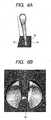
- This state obtained for a pillar-shaped liquid (a liquid pillar) 52 is three-dimensionally shown in FIGS. 6A, 6B and 6C .
- the quantity of the liquid that remains between the projections in the high fluid resistant portion is smaller than the liquid quantity defined according to the diameter of the pillar liquid, the liquid pillar is locally narrowed by the projections, and a "constricted part" is formed.
- FIG. 6A is a perspective view of a simulation showing the state of a liquid pillar viewed from a direction perpendicular to the projections.
- FIG. 6B is an enlarged perspective view of a simulation showing the "constricted part" of the liquid pillar.
- the "constricted part”, formed at the root of the liquid pillar by the upper portions of the projections, is depicted in both directions in FIGS. 6A and 6B .
- the liquid surface (the liquid film), connected to the liquid pillar stretching outside the discharge port, is held in the high fluid resistant area between the projections, and separation of the liquid pillar stretching outside the discharge port is performed in the constricted part of the liquid pillar that is formed in the high fluid resistant area at the upper portions of the projections ( FIG. 6C ). Since the discharged liquid is separated in accordance with this timing, the separation time can be adjusted so that it occurs earlier than the conventional time by 1 to 2 ⁇ sec, or more. That is, assuming that the discharge velocity of a liquid droplet is 15 m/sec, the length of a tail is reduced by equal to or more than 15 to 30 ⁇ m.
- the velocity vector does not indicate a direction opposite to that of the velocity vector of the flying, discharged liquid, and the velocity at the rear end of the liquid droplet is adequately swifter than the conventional velocity. Further, a phenomenon wherein the liquid pillar portion of the discharged liquid is stretched and substantially elongated does not occur, and as a result, the discharged liquid is smoothly separated. And a mist that conventionally occurs upon the separation of the discharged liquid (the liquid pillar) is remarkably suppressed.
- the rear end of the flying liquid droplet becomes spherical, due to surface tension, and is separated into a main droplet and a sub-droplet (satellite).
- a sub-droplet satellite
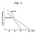
- FIG. 4 is a graph of the relationship between the minimum diameters for the thicknesses of liquid pillars in FIG. 2 (line P), and shows the discharge process of this invention, and in FIG. 10 (line Q) is shown the conventional discharge process and the discharge steps.
- the minimum diameter for the thickness of the liquid pillar is the diameter of the portion, of a liquid pillar forced out through the discharge port, and has the smallest cross section, in the discharge direction, except for the spherical portion that serves as the main droplet.
- (d) to (g) along the horizontal axis correspond to the individual steps in FIGS. 2 and 10 .
- the thicknesses of the initial liquid pillars differ, because the discharge port for this invention is formed by dividing a conventional circular discharge port into two semi-circular segments and inserting projections between the semi-circular segments, so that the maximum diameter of the discharge port is increased, compared with the conventional one.
- the minimum diameter for the thickness of the liquid pillar is reduced at almost a steady rate.
- the change rate changes suddenly, due to the time required to attain the minimum diameter for the thickness of the liquid pillar. This is probably because, as previously described, due to pulling of the local meniscus, accompanied by the bubble disappearance, the quantity of the liquid that contacts the liquid pillar held by the projections is suddenly reduced, and a constricted part is formed at the root of the liquid pillar.
- step (e) it is felt that the thickness of the liquid pillar becomes extremely small, and the separation time for the discharged liquid is advanced and occurs earlier than it does for the conventional time.
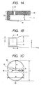
- FIG. 13 is a schematic diagram for the discharge state, of this embodiment, for a BTJ (bubble through jet) during which bubbles communicate with the atmosphere.
- (a) to (g) of FIG. 13 are head cross-sectional views, taken from a direction perpendicular to a projection
- (a) to (g) of FIG. 14 are head cross-sectional views, taken from the direction at a projection. Steps (a) to (g) in FIG. 13 correspond to those of (a) to (g) in FIG. 14 .
- An explanation for the portion corresponding to that of the above described BJ discharge system will be omitted.
- a distance OH, from a heater to a discharge port need only be reduced (to 20 to 30 ⁇ m), compared with the previous BJ example ( FIGS. 1A, 1B and 1C ).
- a bubble grows further upward (the discharge port direction) ((d) of FIG. 13 ), and a meniscus is retracted further inward to the discharge port, and communicates with a bubble in a nozzle ((f) of FIG. 13 ).
- the meniscus is easily retracted, and the state wherein a liquid film is extended between the projections, is prepared at an earlier timing, and the separation time for a liquid droplet is moved forward.
- the separation of a liquid droplet is performed between the projections at the discharge port, and thus, while always in the center of the discharge port, the liquid droplet is separated. Therefore, the linearity of the trajectory is maintained for the flight of a discharged liquid droplet, and the occurrence of a satellite and of the deterioration of an image can be prevented.
- the shape of a projection here represents the shape of a projection, taken when a discharge port is viewed from a liquid discharge direction, i.e., the cross sectional shape of a discharge port, related to the direction in which the liquid is to be discharged.
- the shape of the discharge port in this embodiment is shown in FIG. 17 .
- a length W of the shortest portion in the low fluid resistant area be greater than the shortest distance (inter-projection gap) H formed by projections.
- M ⁇ (L - a)/2 > H be satisfied, wherein M denotes the minimum diameter of the outer edge of a discharge port when a projection is not formed (in the case of two projections as in this embodiment, a distance from the root of one projection to the root of the other.
- a distance from the root of the projection to a corresponding edge) denotes the maximum diameter of the discharge port; a denotes a half-width of a projection; and H denotes a distance from the distal end of a projection to the edge of the discharge port in a direction in which the projection is convex.
- the balance appropriate for the discharge method of this invention is obtained between the area of the circular portion of the discharge port and the area between the projections. More preferably, M ⁇ (L - a). Further, the inter-projection gap H is greater than 0, and when a liquid film is held between the projections, the discharge system for this embodiment is provided.
- the projection area X in FIG. 17 denotes a projection area.
- the projection area X is a rectangle or a square formed of two sides: the length of a projection (x 1 : length from the root to the distal end of a projection) in a direction in which the projection is extended inside the discharge port (direction in which the projection is convex); and the width of the root of a projection in the widthwise direction of the projection (x 2 : linear distance from the bent point at the root of the projection to the bent point on the opposite side across the distal end of the projection).
- x 1 length from the root to the distal end of a projection
- x 2 linear distance from the bent point at the root of the projection to the bent point on the opposite side across the distal end of the projection.
- the liquid pillar is cut on the side of the liquid film close to the surface of the discharge port, and is discharged as a liquid droplet.
- the tail of the discharged liquid droplet becomes short. That is, it is important that the liquid film is held between the projections until the moment at which the liquid droplet is separated, and it is necessary that the distal end of the projections should be shaped to easily hold the liquid film formed between the projections (easily maintain a surface tension).
- FIG. 20 is a schematic diagram for explaining the movement of a liquid inside the discharge port in a bubble fading process according to this embodiment.
- the discharge port of this embodiment employs a shape such that semicircular portions are developed, and projections are inserted in between. Therefore, in the bubble fading process, a force is exerted to low fluid resistant areas shown in FIG. 20 , so that a meniscus is dropped to the heater side in a semi-circular form as indicated in white, and a liquid film between the projections tends to be held as indicated in a hatched manner. Further, linear portions are provided for both sides of the projections, and since the linear portions are parallel to each other, the meniscus at the low fluid resistant portions tends to be dropped more in the semi-circular manner.
- the distal end of a projection may be in a shape having linear portions perpendicular to a direction in which the projection is convex, e.g., the distal end of the projection may be a quadrilateral, and the effects of this embodiment are still obtained.
- the force for holding the liquid film between the projections is high, as shown in the simulation in FIGS. 6B and 6C .
- the liquid film is maintained between the projections. Therefore, the location where the liquid pillar is to be separated from the liquid film is close to the surface of the discharge port, so that the length of the tail of a liquid droplet to be discharged can be shortened, and this results in the reduction of satellites.
- the central axis of the discharge port portion in the liquid discharge direction be perpendicular to the surface of the discharge port and the energy generating element, because of the symmetries of the positions of the meniscus and the stability of discharging.
- the central axis of the discharge port portion is not perpendicular to the surface of the discharge port or the heat generating element, at the bubble fading stage at which the meniscus position in the discharge port portion is moved toward the heat generating element, asymmetries for the meniscus positions are remarkable, and the effects of the invention can not be sufficiently obtained.
- FIGS. 18A, 18B , 19A and 19B show the shapes of projections for comparison examples.
- a discharge port in FIG. 18A is a form provided by connecting two circles. The long side of the discharge port is defined as 20.0 ⁇ m, and the short side is defined as 4.5 ⁇ m.
- x 1 (direction toward the center of a discharge port) is regarded as 2.9 ⁇ m
- x 2 width of the projection root
- x 2 /x 1 3.4.
- a discharging simulation is shown in FIG. 18B , which corresponds to the interval between (e) and (f) in FIG.
- FIG. 19A For a discharge port shown in FIG. 19A , the shape of projections is very blunted.
- the long side of the discharge port is defined as 20.6 ⁇ m, and the short side is defined as 7.7 ⁇ m.
- x 1 (direction toward the center of a discharge port) is regarded as 2.2 ⁇ m, and x 2 (width of the projection root) is regarded as 8.2 ⁇ m.
- x 2 /x 1 3.7.
- FIG. 19B A simulation for this is shown in FIG. 19B , which corresponds to the interval between (e) and (f) in FIG. 3 , or (e) and (f) in FIG. 14 .
- FIG. 19B A simulation for this is shown in FIG. 19B , which corresponds to the interval between (e) and (f) in FIG. 3 , or (e) and (f) in FIG. 14 .
- FIG. 19B A simulation for this is shown in FIG. 19B , which corresponds to the interval between (e
- FIGS. 15, 16A and 16B examples viewed from a direction perpendicular to a heater face are shown in FIGS. 15, 16A and 16B .
- the head structure in FIG. 15 is the shape wherein projections are formed for a two-step discharge port.
- a first discharge port 6 is formed to communicate with a flow path 5 above a heater; a second discharge port 7 smaller than the first discharge port 6 is formed above the first discharge port 6; and projections 10 are formed on the second discharge port 7. Since the first discharge port is large, clogging of a liquid to be discharged can be suppressed, and a tiny liquid droplet can be formed through the second discharge port.
- the tail of a discharged liquid can be reduced at the projections of the second discharge port, and in addition, since the first discharge port portion having a small resistance is included, the discharge efficiency is improved. Further, since the forward resistance of the nozzle is reduced, a bubble easily grows upward in the discharge port, and during bubble fading, a meniscus can be pulled in the nozzle with a great force, so that the state wherein a liquid film is extended between the projections can be prepared earlier, and separation time for a liquid droplet is advanced.
- FIGS. 16A and 16B are diagrams showing projections in tapered shapes.
- a discharge port is formed linearly in the discharge direction, and projections are tapered so as to be narrowed in the discharge direction.
- a discharge portion and projections are tapered so as to be narrowed in the discharged direction. Since the resistance in the discharge direction is reduced by employing such a shape, the same effects as provided by the above described two-step discharge port can be obtained, and such effects as the increase of the discharge efficiency and the reduction of a liquid droplet separation period are produced. Further, in FIG. 16B , the same tapered angle may be employed for the discharge port and the projections; however, it is preferable that the projections be more tapered in the discharge direction.
- the central axis of the discharge port portion in the liquid discharge direction be perpendicular to the surface of the discharge port and the heat generating element, and that both the two-step shape and the tapered shape symmetrical relative to the central axis of the discharge port portion, while taking into account the symmetries of meniscus positions and stability of discharging.
- the number of projections is not limited to two, and a case of one projection as shown in FIG. 5A , or a case of three projections as shown in FIG. 5B is also included.
- an inter-projection gap H denotes the shortest distance from the distal end of the projection to the outer edge of a discharge port.
- a projection may be thinner than a member where a discharge port is to be formed.
- different sizes may be provided for these projections. It is not preferable that too many projections be formed, because the shape of a discharge port becomes complicated, and clogging of a liquid easily occurs.
- the substrate 34 can serve as one part of a flow path formation member, and can function as a support member for a heat generating element, a flow path, a discharge port plate, etc.
- its material is not especially limited, and glass, ceramics, plastic or metal, for example, can be employed.
- an Si substrate wafer
- Formation of discharge ports can be performed by using a laser beam, or also an exposure apparatus, such as an MPA (Mirror Projection Aligner) can be employed to utilize a photosensitive resin as the discharge port plate 35 to form discharge ports.
- the flow path wall 36 is formed on the substrate 34 by a method such as spin coating, and the ink flow path wall 36 and the discharge port plate 35 can be obtained as one member at the same time.
- discharge ports may be patterned through lithography.
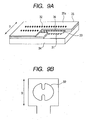
- FIGS. 11A, 11B, 11C, 11D, 11E and 11F are schematic diagrams showing the head manufacturing processing for this embodiment.
- the silicon substrate 34 wherein a drive circuit and the heaters 31 are mounted is prepared ( FIG. 11A ).
- a photosensitive resin is applied to the silicon substrate 34 in FIG. 34A, and exposure and developing is performed to pattern a portion 38 serving as flow paths ( FIG. 11B ).
- a photosensitive resin 36 which becomes a flow path wall and a discharge port plate, is applied so as to cover the portion 38 serving as flow paths ( FIG. 11C ).
- Exposure and developing is performed for the photosensitive resin 36 to pattern discharge ports 32 that include projections 10 in a convex shape ( FIG. 11D ).
- the ink supply port 33 is formed from the reverse side of the flow path formation face of the silicon substrate 34 ( FIG. 11E ). Finally, a photosensitive resin 38 located at the flow path portions are melted by a solvent, and the melted portions become ink flow paths, and a hollow head is completed ( FIG. 11F ). For the thus obtained head portion, electrical mounting is performed, and a supply path, for supplying ink to the head portion from an ink tank, is formed, and a head cartridge is provided.
- the state wherein a liquid was discharged was observed by stroboscopic photography, and a period required for separating a discharged liquid and the length of a liquid droplet from the distal end to the rear end of the liquid droplet immediately after the discharged liquid was separated were measured.
- the separation period for the discharged liquid is regarded as a period since a voltage was applied to heaters until a liquid pillar was separated from a liquid film. Power on time for the heaters was adjusted so that the discharge speed of 13 m/s was obtained.
- the number of satellites is the average of ten samples of the number of satellites observed at one discharge. Further, the number of particles changed to a mist was also measured.
- a pair of projections 10 is so formed that, in the cross section of the discharge port in the discharge direction, the distal ends of the projections are directed to the gravity center of the discharge port, and the linear line connecting the distal ends runs through the center of the discharge port.
- the length x 1 of the projections in a direction in which the projections are convex is equal to the projection length b.
- the minimum diameter M of the virtual edge of a discharge port denotes a distance from the root of one projection to the root of the other projection, and is equal to the diameter ⁇ of the discharge port in the table.
- the largest diameter L of the discharge port is a value obtained by adding the projection width a to the value of ⁇ in the table.
- the minimum diameter H of the discharge port denotes a gap between the projections, and is a value obtained by subtracting a value of b ⁇ 2 from the value of ⁇ .
- the height h of the flow paths 5 is 14 ⁇ m.
- a distance (OH) from the heaters 31, which are heat generating elements, to the surface of the discharge port plate 35, is 25 ⁇ m.
- the size of each heater 31 arranged in the bubble chamber where bubbles are generated is 17.6 ⁇ 17.6 ⁇ m.
- the long side L of each discharge port is 19.6 ⁇ m.
- the short side M of the virtual outer edge of the discharge port which is the distance from the root of one projection 10 to the root of the other projection, is 16.6 ⁇ m.
- the length b of the projection is 5.9 ⁇ m
- the half-width a of the projection is 3 ⁇ m
- the distance H from the distal end of one projection to the distal end of the other projection is 4.2 ⁇ m.
- the distal ends of the projections 10 have a curvature diameter R of 2.2 ⁇ m, and are rounded.
- the discharge volume is about 5.4 ng.
- the projections are as thick as the discharge port plate.
- the discharge port has such a shape that a circle of a diameter ⁇ 16.6 ⁇ m is divided into two semi-circular portions, and projections are inserted between the semi-circular portions. Power to the heater was adjusted so as to obtain the liquid droplet discharge speed of 13 m/s, and discharge by this head was performed.
- a circular discharge port having a diameter of ⁇ 16.6 ⁇ m was employed as a head for comparison example 1-1.
- the other structure is the same as for embodiment 1.
- the discharge volume was 5.8 ng.
- the discharged liquid separation period was 11 ⁇ sec, while 8.5 ⁇ sec was required in embodiment 1, and the period until the discharged liquid was separated was considerably reduced in embodiment 1.
- the length of a liquid droplet was 117 ⁇ m in embodiment 1, and was 156 ⁇ m for the head in comparison example 1-1.
- comparison example 1-2 shows an example discharge port that has a different discharge speed from that of embodiment 1, but has substantially the same length of a liquid droplet, and employs a circle having a diameter of 13 ⁇ m as the shape of a discharge port.
- the discharge volume at this time was 3 ng.
- a discharged liquid separation period was 10 ⁇ sec
- the length of a liquid droplet was 116 ⁇ m
- the number of satellites was 2.2.
- Embodiment 2-1 is an example wherein projections are inserted between semi-circular portions of a diameter of 11 ⁇ m, as shown in FIG. 17 , and the relationship between M, L and H and the values in the table is the same as that for embodiment 1.
- x 2 /x 1 1.35 and x 1 ⁇ x 2
- the discharge quantity is 1.7 ng.
- Comparison example 2 employs a circular discharge port of a diameter of 11 ⁇ m, and the discharge quantity is 1.5 ng.
- the liquid separation time was advanced, compared with the circular one in comparison example. Further, it could be confirmed that the discharged liquid droplet was shortened, and the number of satellites was reduced. Additionally, the number of particles changed as a mist was sharply reduced.
- Embodiments 3-1 to 3-5 are examples wherein projections of sizes written in the table are inserted between semi-circular portions of a diameter of 11 ⁇ m, as shown in FIG. 17 , and the relationship between M, L and H and the values in the table is the same as that for embodiment 1.
- the discharge quantity is 1.7 ng.
- Comparison example 3-1 employs a circular discharge port having a diameter of 11 ⁇ m, and the discharge quantity is 1.6 ng.
- Comparison example 3-2 employs the shape wherein projections of a length 0.7 are inserted between semi-circular portions of a diameter of 11 ⁇ m, and the discharge quantity is 1.7 ng.
- the discharged liquid separation time, the length of the liquid droplet and the satellites were all increased, compared with the embodiments.
- Embodiment 4 is an example wherein projections of sizes written in the table are inserted between semi-circular portions of a diameter of 13 ⁇ m, as shown in FIG. 17 , and the relationship between M, L and H and the values in the table is the same as that for embodiment 1.
- x 2 /x 1 0.8 and x 1 ⁇ x 2 .
- the discharge quantity is 2.3 ng.
- Comparison example 4 employs a circular discharge port having a diameter of 13 ⁇ m and the discharge quantity is 2.3 ng. According to this, for the head in this embodiment that has projections, it was confirmed that, compared with the circular one in the comparison example, the liquid separation time was advanced, the discharged liquid droplet was shortened and the satellites were reduced.
- Embodiment 5 is an example wherein projections of the size written in the table were inserted between the semi-circular portions having a diameter of 14.3 ⁇ m, and the relationship between M, L and H and the values in the table is the same as that for embodiment 1.
- x 2 /x 1 0.9 and x 1 ⁇ x 2 .
- Comparison example 5 employs a circular discharge port having a diameter of 13.6 ⁇ m, and the diameter of the discharge port was selected so as to match the discharge quantity of 4.0 ng in embodiment 5. Since the discharge speed for a liquid droplet is faster than in the above embodiment, the number of satellites is increased more than in the above embodiment.
- the liquid separation time was advanced, the length of the discharged liquid droplet was reduced and the satellites were reduced. Further, the number of particles changed as a mist were also drastically reduced.
- the head of the embodiments by using the head of the embodiments, the degrading of an image quality due to satellite liquid droplets or a mist can be reduced.
- an example using heaters as energy generating elements has been employed.
- the present invention is not limited to this, and can be applied for a case using, for example, a piezoelectric member.
- a bubble fading process is not required, but by applying an electric signal to the piezoelectric member to expand a liquid chamber, the meniscus can be pulled inside a discharge port.
Landscapes
- Physics & Mathematics (AREA)
- Geometry (AREA)
- Engineering & Computer Science (AREA)
- Manufacturing & Machinery (AREA)
- Particle Formation And Scattering Control In Inkjet Printers (AREA)
- Ink Jet (AREA)
- Coating Apparatus (AREA)
Applications Claiming Priority (2)
| Application Number | Priority Date | Filing Date | Title |
|---|---|---|---|
| JP2005343943 | 2005-11-29 | ||
| EP06834070.2A EP1961573B1 (en) | 2005-11-29 | 2006-11-29 | Method of liquid discharge |
Related Parent Applications (1)
| Application Number | Title | Priority Date | Filing Date |
|---|---|---|---|
| EP06834070.2 Division | 2006-11-29 |
Publications (2)
| Publication Number | Publication Date |
|---|---|
| EP2402161A1 EP2402161A1 (en) | 2012-01-04 |
| EP2402161B1 true EP2402161B1 (en) | 2013-10-16 |
Family
ID=38092351
Family Applications (2)
| Application Number | Title | Priority Date | Filing Date |
|---|---|---|---|
| EP11181409.1A Not-in-force EP2402161B1 (en) | 2005-11-29 | 2006-11-29 | Method of liquid discharge, liquid discharge head |
| EP06834070.2A Not-in-force EP1961573B1 (en) | 2005-11-29 | 2006-11-29 | Method of liquid discharge |
Family Applications After (1)
| Application Number | Title | Priority Date | Filing Date |
|---|---|---|---|
| EP06834070.2A Not-in-force EP1961573B1 (en) | 2005-11-29 | 2006-11-29 | Method of liquid discharge |
Country Status (8)
| Country | Link |
|---|---|
| US (5) | US7506962B2 (ko) |
| EP (2) | EP2402161B1 (ko) |
| JP (3) | JP4818276B2 (ko) |
| KR (2) | KR101069094B1 (ko) |
| CN (3) | CN101316712B (ko) |
| RU (2) | RU2375196C1 (ko) |
| TW (1) | TW200732162A (ko) |
| WO (1) | WO2007064021A1 (ko) |
Families Citing this family (29)
| Publication number | Priority date | Publication date | Assignee | Title |
|---|---|---|---|---|
| EP2402161B1 (en) * | 2005-11-29 | 2013-10-16 | Canon Kabushiki Kaisha | Method of liquid discharge, liquid discharge head |
| JP5020708B2 (ja) | 2007-05-25 | 2012-09-05 | キヤノン株式会社 | 液体吐出ヘッドおよびインクジェット記録装置 |
| JP5031534B2 (ja) * | 2007-11-30 | 2012-09-19 | キヤノン株式会社 | インクジェット記録ヘッド |
| JP5393082B2 (ja) * | 2008-08-29 | 2014-01-22 | キヤノン株式会社 | 液体吐出ヘッド |
| US8267501B2 (en) * | 2009-08-20 | 2012-09-18 | Eastman Kodak Company | Drop ejector having multi-lobed nozzle |
| CN102905902B (zh) * | 2010-03-31 | 2016-03-09 | 惠普发展公司,有限责任合伙企业 | 非圆形喷墨喷嘴 |
| US10717278B2 (en) | 2010-03-31 | 2020-07-21 | Hewlett-Packard Development Company, L.P. | Noncircular inkjet nozzle |
| US8783831B2 (en) | 2011-01-31 | 2014-07-22 | Hewlett-Packard Development Company, L.P. | Fluid ejection device having firing chamber with contoured floor |
| ITTO20120426A1 (it) * | 2012-05-11 | 2013-11-12 | St Microelectronics Srl | Processo di fabbricazione di una piastra degli ugelli, piastra degli ugelli, e dispositivo di eiezione di liquido dotato della piastra degli ugelli |
| JP5901149B2 (ja) | 2011-06-01 | 2016-04-06 | キヤノン株式会社 | 液体吐出ヘッドおよびその製造方法 |
| JP5804787B2 (ja) | 2011-06-13 | 2015-11-04 | キヤノン株式会社 | 記録ヘッドおよびインクジェット記録装置 |
| JP5875293B2 (ja) * | 2011-08-25 | 2016-03-02 | キヤノン株式会社 | 記録ヘッドおよびインクジェット記録装置 |
| CN104755269B (zh) * | 2012-10-30 | 2016-12-28 | 佳能株式会社 | 液体喷出头 |
| JP2014124917A (ja) * | 2012-12-27 | 2014-07-07 | Canon Inc | 記録ヘッド |
| JP6271898B2 (ja) | 2013-07-29 | 2018-01-31 | キヤノン株式会社 | 液体吐出ヘッド及び記録装置 |
| JP2016049680A (ja) * | 2014-08-29 | 2016-04-11 | キヤノン株式会社 | 素子基板および液体吐出ヘッド |
| EP3000602B1 (en) * | 2014-09-26 | 2020-07-22 | Agfa Nv | High viscosity jetting method |
| JP6877970B2 (ja) * | 2016-01-08 | 2021-05-26 | キヤノン株式会社 | 液体吐出ヘッド及び液体吐出方法 |
| JP6818436B2 (ja) * | 2016-05-27 | 2021-01-20 | キヤノン株式会社 | 記録素子基板、液体吐出ヘッドおよび液体吐出装置 |
| JP6860305B2 (ja) | 2016-07-22 | 2021-04-14 | キヤノン株式会社 | 液体吐出ヘッド及び液体吐出装置 |
| US10189253B2 (en) | 2016-09-28 | 2019-01-29 | Canon Kabushiki Kaisha | Liquid ejection head and method for producing the same |
| US10926537B2 (en) | 2017-04-24 | 2021-02-23 | Hewlett-Packard Development Company, L.P. | Fluid back pressure sensing with a strain sensor |
| JP2018199235A (ja) * | 2017-05-26 | 2018-12-20 | キヤノン株式会社 | 液体吐出ヘッド |
| JP2018202805A (ja) | 2017-06-08 | 2018-12-27 | キヤノン株式会社 | 液体吐出ヘッド及びその製造方法並びに印字装置 |
| US10556433B2 (en) | 2018-01-29 | 2020-02-11 | Canon Kabushiki Kaisha | Liquid discharge apparatus and cleaning method for liquid discharge head |
| JP7118716B2 (ja) | 2018-04-17 | 2022-08-16 | キヤノン株式会社 | 液体吐出ヘッド |
| JP7392290B2 (ja) * | 2019-05-30 | 2023-12-06 | セイコーエプソン株式会社 | 吐出ヘッド |
| JP7362386B2 (ja) | 2019-09-19 | 2023-10-17 | キヤノン株式会社 | 記録装置、記録装置の制御方法 |
| JP2021133647A (ja) * | 2020-02-28 | 2021-09-13 | キヤノン株式会社 | 液体吐出ヘッド |
Family Cites Families (13)
| Publication number | Priority date | Publication date | Assignee | Title |
|---|---|---|---|---|
| JPH022004A (ja) * | 1988-06-10 | 1990-01-08 | Seiko Epson Corp | インクジェットヘッド |
| US6254219B1 (en) | 1995-10-25 | 2001-07-03 | Hewlett-Packard Company | Inkjet printhead orifice plate having related orifices |
| US6123413A (en) * | 1995-10-25 | 2000-09-26 | Hewlett-Packard Company | Reduced spray inkjet printhead orifice |
| US6557974B1 (en) | 1995-10-25 | 2003-05-06 | Hewlett-Packard Company | Non-circular printhead orifice |
| US6527369B1 (en) * | 1995-10-25 | 2003-03-04 | Hewlett-Packard Company | Asymmetric printhead orifice |
| US6371596B1 (en) * | 1995-10-25 | 2002-04-16 | Hewlett-Packard Company | Asymmetric ink emitting orifices for improved inkjet drop formation |
| US6350016B1 (en) | 1998-02-10 | 2002-02-26 | Canon Kabushiki Kaisha | Liquid ejecting method and liquid ejecting head |
| JP3675272B2 (ja) | 1999-01-29 | 2005-07-27 | キヤノン株式会社 | 液体吐出ヘッドおよびその製造方法 |
| KR100408268B1 (ko) * | 2000-07-20 | 2003-12-01 | 삼성전자주식회사 | 버블 젯 방식의 잉크 젯 프린트 헤드 및 그 제조방법 |
| JP4027281B2 (ja) | 2002-07-10 | 2007-12-26 | キヤノン株式会社 | インクジェット記録ヘッド |
| JP4027282B2 (ja) | 2002-07-10 | 2007-12-26 | キヤノン株式会社 | インクジェット記録ヘッド |
| JP2005343943A (ja) | 2004-06-01 | 2005-12-15 | Shiseido Co Ltd | 水中油型洗浄剤組成物およびシート状洗浄剤 |
| EP2402161B1 (en) * | 2005-11-29 | 2013-10-16 | Canon Kabushiki Kaisha | Method of liquid discharge, liquid discharge head |
-
2006
- 2006-11-29 EP EP11181409.1A patent/EP2402161B1/en not_active Not-in-force
- 2006-11-29 JP JP2007548036A patent/JP4818276B2/ja active Active
- 2006-11-29 CN CN200680044668XA patent/CN101316712B/zh not_active Expired - Fee Related
- 2006-11-29 KR KR1020087015621A patent/KR101069094B1/ko active IP Right Grant
- 2006-11-29 CN CN2010101397458A patent/CN101875261B/zh not_active Expired - Fee Related
- 2006-11-29 KR KR1020107027814A patent/KR101087437B1/ko active IP Right Grant
- 2006-11-29 EP EP06834070.2A patent/EP1961573B1/en not_active Not-in-force
- 2006-11-29 WO PCT/JP2006/324315 patent/WO2007064021A1/ja active Application Filing
- 2006-11-29 RU RU2008126284/12A patent/RU2375196C1/ru active
- 2006-11-29 CN CN201110127871.6A patent/CN102248792B/zh not_active Expired - Fee Related
- 2006-11-29 TW TW095144225A patent/TW200732162A/zh not_active IP Right Cessation
-
2007
- 2007-03-07 US US11/683,154 patent/US7506962B2/en active Active
-
2009
- 2009-01-26 US US12/359,522 patent/US7926912B2/en active Active
- 2009-08-14 RU RU2009131112/05A patent/RU2415021C1/ru active
-
2011
- 2011-03-11 US US13/046,178 patent/US8167407B2/en active Active
- 2011-03-11 US US13/046,215 patent/US8025362B2/en active Active
- 2011-07-26 JP JP2011163504A patent/JP4818480B1/ja active Active
- 2011-07-26 JP JP2011163503A patent/JP5100866B2/ja active Active
- 2011-08-19 US US13/213,439 patent/US8382248B2/en active Active
Also Published As
Similar Documents
| Publication | Publication Date | Title |
|---|---|---|
| EP2402161B1 (en) | Method of liquid discharge, liquid discharge head | |
| EP1995069B1 (en) | Liquid ejecting head and ink jet printing apparatus | |
| EP1024008B1 (en) | Liquid ejection head, method for preventing accidental non-ejection using the ejection head and manufacturing method of the ejection head | |
| EP2646251B1 (en) | Noncircular inkjet nozzle | |
| US7625080B2 (en) | Air management in a fluid ejection device | |
| US7824009B2 (en) | Liquid ejection head | |
| JP2002283580A (ja) | 完全に一体化した熱インクジェットプリントヘッド用のインク供給トレンチエッチング技術 | |
| US6893577B2 (en) | Method of forming substrate for fluid ejection device | |
| JP2008018675A (ja) | インクジェット記録ヘッド | |
| JP2005212133A (ja) | 液体噴射記録ヘッド | |
| EP0493039A2 (en) | Thermal ink jet printhead having an increased drop velocity |
Legal Events
| Date | Code | Title | Description |
|---|---|---|---|
| AC | Divisional application: reference to earlier application |
Ref document number: 1961573 Country of ref document: EP Kind code of ref document: P |
|
| AK | Designated contracting states |
Kind code of ref document: A1 Designated state(s): AT BE BG CH CY CZ DE DK EE ES FI FR GB GR HU IE IS IT LI LT LU LV MC NL PL PT RO SE SI SK TR |
|
| AX | Request for extension of the european patent |
Extension state: AL BA HR MK RS |
|
| PUAI | Public reference made under article 153(3) epc to a published international application that has entered the european phase |
Free format text: ORIGINAL CODE: 0009012 |
|
| 17P | Request for examination filed |
Effective date: 20120704 |
|
| GRAP | Despatch of communication of intention to grant a patent |
Free format text: ORIGINAL CODE: EPIDOSNIGR1 |
|
| INTG | Intention to grant announced |
Effective date: 20130507 |
|
| GRAS | Grant fee paid |
Free format text: ORIGINAL CODE: EPIDOSNIGR3 |
|
| GRAA | (expected) grant |
Free format text: ORIGINAL CODE: 0009210 |
|
| STAA | Information on the status of an ep patent application or granted ep patent |
Free format text: STATUS: THE PATENT HAS BEEN GRANTED |
|
| AC | Divisional application: reference to earlier application |
Ref document number: 1961573 Country of ref document: EP Kind code of ref document: P |
|
| AK | Designated contracting states |
Kind code of ref document: B1 Designated state(s): AT BE BG CH CY CZ DE DK EE ES FI FR GB GR HU IE IS IT LI LT LU LV MC NL PL PT RO SE SI SK TR |
|
| REG | Reference to a national code |
Ref country code: GB Ref legal event code: FG4D |
|
| REG | Reference to a national code |
Ref country code: CH Ref legal event code: EP |
|
| REG | Reference to a national code |
Ref country code: IE Ref legal event code: FG4D |
|
| REG | Reference to a national code |
Ref country code: AT Ref legal event code: REF Ref document number: 636276 Country of ref document: AT Kind code of ref document: T Effective date: 20131115 |
|
| REG | Reference to a national code |
Ref country code: DE Ref legal event code: R096 Ref document number: 602006038909 Country of ref document: DE Effective date: 20131205 |
|
| REG | Reference to a national code |
Ref country code: NL Ref legal event code: VDEP Effective date: 20131016 |
|
| REG | Reference to a national code |
Ref country code: AT Ref legal event code: MK05 Ref document number: 636276 Country of ref document: AT Kind code of ref document: T Effective date: 20131016 |
|
| REG | Reference to a national code |
Ref country code: LT Ref legal event code: MG4D |
|
| PG25 | Lapsed in a contracting state [announced via postgrant information from national office to epo] |
Ref country code: FI Free format text: LAPSE BECAUSE OF FAILURE TO SUBMIT A TRANSLATION OF THE DESCRIPTION OR TO PAY THE FEE WITHIN THE PRESCRIBED TIME-LIMIT Effective date: 20131016 Ref country code: SE Free format text: LAPSE BECAUSE OF FAILURE TO SUBMIT A TRANSLATION OF THE DESCRIPTION OR TO PAY THE FEE WITHIN THE PRESCRIBED TIME-LIMIT Effective date: 20131016 Ref country code: IS Free format text: LAPSE BECAUSE OF FAILURE TO SUBMIT A TRANSLATION OF THE DESCRIPTION OR TO PAY THE FEE WITHIN THE PRESCRIBED TIME-LIMIT Effective date: 20140216 Ref country code: LT Free format text: LAPSE BECAUSE OF FAILURE TO SUBMIT A TRANSLATION OF THE DESCRIPTION OR TO PAY THE FEE WITHIN THE PRESCRIBED TIME-LIMIT Effective date: 20131016 Ref country code: NL Free format text: LAPSE BECAUSE OF FAILURE TO SUBMIT A TRANSLATION OF THE DESCRIPTION OR TO PAY THE FEE WITHIN THE PRESCRIBED TIME-LIMIT Effective date: 20131016 Ref country code: BE Free format text: LAPSE BECAUSE OF FAILURE TO SUBMIT A TRANSLATION OF THE DESCRIPTION OR TO PAY THE FEE WITHIN THE PRESCRIBED TIME-LIMIT Effective date: 20131016 |
|
| PG25 | Lapsed in a contracting state [announced via postgrant information from national office to epo] |
Ref country code: AT Free format text: LAPSE BECAUSE OF FAILURE TO SUBMIT A TRANSLATION OF THE DESCRIPTION OR TO PAY THE FEE WITHIN THE PRESCRIBED TIME-LIMIT Effective date: 20131016 Ref country code: CY Free format text: LAPSE BECAUSE OF FAILURE TO SUBMIT A TRANSLATION OF THE DESCRIPTION OR TO PAY THE FEE WITHIN THE PRESCRIBED TIME-LIMIT Effective date: 20131016 Ref country code: LV Free format text: LAPSE BECAUSE OF FAILURE TO SUBMIT A TRANSLATION OF THE DESCRIPTION OR TO PAY THE FEE WITHIN THE PRESCRIBED TIME-LIMIT Effective date: 20131016 Ref country code: ES Free format text: LAPSE BECAUSE OF FAILURE TO SUBMIT A TRANSLATION OF THE DESCRIPTION OR TO PAY THE FEE WITHIN THE PRESCRIBED TIME-LIMIT Effective date: 20131016 |
|
| PG25 | Lapsed in a contracting state [announced via postgrant information from national office to epo] |
Ref country code: PT Free format text: LAPSE BECAUSE OF FAILURE TO SUBMIT A TRANSLATION OF THE DESCRIPTION OR TO PAY THE FEE WITHIN THE PRESCRIBED TIME-LIMIT Effective date: 20140217 |
|
| REG | Reference to a national code |
Ref country code: CH Ref legal event code: PL |
|
| REG | Reference to a national code |
Ref country code: DE Ref legal event code: R097 Ref document number: 602006038909 Country of ref document: DE |
|
| PG25 | Lapsed in a contracting state [announced via postgrant information from national office to epo] |
Ref country code: EE Free format text: LAPSE BECAUSE OF FAILURE TO SUBMIT A TRANSLATION OF THE DESCRIPTION OR TO PAY THE FEE WITHIN THE PRESCRIBED TIME-LIMIT Effective date: 20131016 Ref country code: MC Free format text: LAPSE BECAUSE OF FAILURE TO SUBMIT A TRANSLATION OF THE DESCRIPTION OR TO PAY THE FEE WITHIN THE PRESCRIBED TIME-LIMIT Effective date: 20131016 Ref country code: CH Free format text: LAPSE BECAUSE OF NON-PAYMENT OF DUE FEES Effective date: 20131130 Ref country code: LI Free format text: LAPSE BECAUSE OF NON-PAYMENT OF DUE FEES Effective date: 20131130 |
|
| PLBE | No opposition filed within time limit |
Free format text: ORIGINAL CODE: 0009261 |
|
| STAA | Information on the status of an ep patent application or granted ep patent |
Free format text: STATUS: NO OPPOSITION FILED WITHIN TIME LIMIT |
|
| REG | Reference to a national code |
Ref country code: IE Ref legal event code: MM4A |
|
| PG25 | Lapsed in a contracting state [announced via postgrant information from national office to epo] |
Ref country code: PL Free format text: LAPSE BECAUSE OF FAILURE TO SUBMIT A TRANSLATION OF THE DESCRIPTION OR TO PAY THE FEE WITHIN THE PRESCRIBED TIME-LIMIT Effective date: 20131016 Ref country code: CZ Free format text: LAPSE BECAUSE OF FAILURE TO SUBMIT A TRANSLATION OF THE DESCRIPTION OR TO PAY THE FEE WITHIN THE PRESCRIBED TIME-LIMIT Effective date: 20131016 Ref country code: SK Free format text: LAPSE BECAUSE OF FAILURE TO SUBMIT A TRANSLATION OF THE DESCRIPTION OR TO PAY THE FEE WITHIN THE PRESCRIBED TIME-LIMIT Effective date: 20131016 Ref country code: RO Free format text: LAPSE BECAUSE OF FAILURE TO SUBMIT A TRANSLATION OF THE DESCRIPTION OR TO PAY THE FEE WITHIN THE PRESCRIBED TIME-LIMIT Effective date: 20131016 |
|
| 26N | No opposition filed |
Effective date: 20140717 |
|
| PG25 | Lapsed in a contracting state [announced via postgrant information from national office to epo] |
Ref country code: DK Free format text: LAPSE BECAUSE OF FAILURE TO SUBMIT A TRANSLATION OF THE DESCRIPTION OR TO PAY THE FEE WITHIN THE PRESCRIBED TIME-LIMIT Effective date: 20131016 |
|
| REG | Reference to a national code |
Ref country code: DE Ref legal event code: R097 Ref document number: 602006038909 Country of ref document: DE Effective date: 20140717 |
|
| PG25 | Lapsed in a contracting state [announced via postgrant information from national office to epo] |
Ref country code: IE Free format text: LAPSE BECAUSE OF NON-PAYMENT OF DUE FEES Effective date: 20131129 |
|
| PG25 | Lapsed in a contracting state [announced via postgrant information from national office to epo] |
Ref country code: SI Free format text: LAPSE BECAUSE OF FAILURE TO SUBMIT A TRANSLATION OF THE DESCRIPTION OR TO PAY THE FEE WITHIN THE PRESCRIBED TIME-LIMIT Effective date: 20131016 |
|
| PG25 | Lapsed in a contracting state [announced via postgrant information from national office to epo] |
Ref country code: TR Free format text: LAPSE BECAUSE OF FAILURE TO SUBMIT A TRANSLATION OF THE DESCRIPTION OR TO PAY THE FEE WITHIN THE PRESCRIBED TIME-LIMIT Effective date: 20131016 |
|
| PG25 | Lapsed in a contracting state [announced via postgrant information from national office to epo] |
Ref country code: LU Free format text: LAPSE BECAUSE OF NON-PAYMENT OF DUE FEES Effective date: 20131129 Ref country code: HU Free format text: LAPSE BECAUSE OF FAILURE TO SUBMIT A TRANSLATION OF THE DESCRIPTION OR TO PAY THE FEE WITHIN THE PRESCRIBED TIME-LIMIT; INVALID AB INITIO Effective date: 20061129 Ref country code: BG Free format text: LAPSE BECAUSE OF FAILURE TO SUBMIT A TRANSLATION OF THE DESCRIPTION OR TO PAY THE FEE WITHIN THE PRESCRIBED TIME-LIMIT Effective date: 20131016 |
|
| PG25 | Lapsed in a contracting state [announced via postgrant information from national office to epo] |
Ref country code: GR Free format text: LAPSE BECAUSE OF NON-PAYMENT OF DUE FEES Effective date: 20131016 |
|
| REG | Reference to a national code |
Ref country code: FR Ref legal event code: PLFP Year of fee payment: 10 |
|
| PG25 | Lapsed in a contracting state [announced via postgrant information from national office to epo] |
Ref country code: GR Free format text: LAPSE BECAUSE OF FAILURE TO SUBMIT A TRANSLATION OF THE DESCRIPTION OR TO PAY THE FEE WITHIN THE PRESCRIBED TIME-LIMIT Effective date: 20140117 |
|
| REG | Reference to a national code |
Ref country code: FR Ref legal event code: PLFP Year of fee payment: 11 |
|
| REG | Reference to a national code |
Ref country code: FR Ref legal event code: PLFP Year of fee payment: 12 |
|
| PGFP | Annual fee paid to national office [announced via postgrant information from national office to epo] |
Ref country code: GB Payment date: 20211020 Year of fee payment: 16 Ref country code: DE Payment date: 20211020 Year of fee payment: 16 |
|
| PGFP | Annual fee paid to national office [announced via postgrant information from national office to epo] |
Ref country code: IT Payment date: 20211025 Year of fee payment: 16 Ref country code: FR Payment date: 20211020 Year of fee payment: 16 |
|
| REG | Reference to a national code |
Ref country code: DE Ref legal event code: R119 Ref document number: 602006038909 Country of ref document: DE |
|
| GBPC | Gb: european patent ceased through non-payment of renewal fee |
Effective date: 20221129 |
|
| PG25 | Lapsed in a contracting state [announced via postgrant information from national office to epo] |
Ref country code: IT Free format text: LAPSE BECAUSE OF NON-PAYMENT OF DUE FEES Effective date: 20221129 Ref country code: GB Free format text: LAPSE BECAUSE OF NON-PAYMENT OF DUE FEES Effective date: 20221129 Ref country code: DE Free format text: LAPSE BECAUSE OF NON-PAYMENT OF DUE FEES Effective date: 20230601 |
|
| PG25 | Lapsed in a contracting state [announced via postgrant information from national office to epo] |
Ref country code: FR Free format text: LAPSE BECAUSE OF NON-PAYMENT OF DUE FEES Effective date: 20221130 |