EP2400262B1 - Verfahren zur überprüfung der qualität einer glasplatte, verfahren zur messung der form einer glasplatte und verfahren zur erstellung einer glasplatte - Google Patents
Verfahren zur überprüfung der qualität einer glasplatte, verfahren zur messung der form einer glasplatte und verfahren zur erstellung einer glasplatte Download PDFInfo
- Publication number
- EP2400262B1 EP2400262B1 EP10738558.5A EP10738558A EP2400262B1 EP 2400262 B1 EP2400262 B1 EP 2400262B1 EP 10738558 A EP10738558 A EP 10738558A EP 2400262 B1 EP2400262 B1 EP 2400262B1
- Authority
- EP
- European Patent Office
- Prior art keywords
- glass plate
- design data
- data
- weight
- actual measurement
- Prior art date
- Legal status (The legal status is an assumption and is not a legal conclusion. Google has not performed a legal analysis and makes no representation as to the accuracy of the status listed.)
- Active
Links
Images





Classifications
-
- G—PHYSICS
- G01—MEASURING; TESTING
- G01B—MEASURING LENGTH, THICKNESS OR SIMILAR LINEAR DIMENSIONS; MEASURING ANGLES; MEASURING AREAS; MEASURING IRREGULARITIES OF SURFACES OR CONTOURS
- G01B21/00—Measuring arrangements or details thereof, where the measuring technique is not covered by the other groups of this subclass, unspecified or not relevant
- G01B21/20—Measuring arrangements or details thereof, where the measuring technique is not covered by the other groups of this subclass, unspecified or not relevant for measuring contours or curvatures, e.g. determining profile
-
- G—PHYSICS
- G01—MEASURING; TESTING
- G01B—MEASURING LENGTH, THICKNESS OR SIMILAR LINEAR DIMENSIONS; MEASURING ANGLES; MEASURING AREAS; MEASURING IRREGULARITIES OF SURFACES OR CONTOURS
- G01B11/00—Measuring arrangements characterised by the use of optical techniques
- G01B11/24—Measuring arrangements characterised by the use of optical techniques for measuring contours or curvatures
- G01B11/25—Measuring arrangements characterised by the use of optical techniques for measuring contours or curvatures by projecting a pattern, e.g. one or more lines, moiré fringes on the object
- G01B11/2509—Color coding
-
- G—PHYSICS
- G01—MEASURING; TESTING
- G01B—MEASURING LENGTH, THICKNESS OR SIMILAR LINEAR DIMENSIONS; MEASURING ANGLES; MEASURING AREAS; MEASURING IRREGULARITIES OF SURFACES OR CONTOURS
- G01B11/00—Measuring arrangements characterised by the use of optical techniques
- G01B11/16—Measuring arrangements characterised by the use of optical techniques for measuring the deformation in a solid, e.g. optical strain gauge
-
- G—PHYSICS
- G01—MEASURING; TESTING
- G01B—MEASURING LENGTH, THICKNESS OR SIMILAR LINEAR DIMENSIONS; MEASURING ANGLES; MEASURING AREAS; MEASURING IRREGULARITIES OF SURFACES OR CONTOURS
- G01B11/00—Measuring arrangements characterised by the use of optical techniques
- G01B11/24—Measuring arrangements characterised by the use of optical techniques for measuring contours or curvatures
- G01B11/25—Measuring arrangements characterised by the use of optical techniques for measuring contours or curvatures by projecting a pattern, e.g. one or more lines, moiré fringes on the object
Definitions
- the present invention relates to a quality inspection method of a glass plate, in particular, to a quality inspection method suitable for inspecting the shape of an automotive window glass.
- window glasses for automobiles ones having various curved shapes accommodated to designs of automobiles.
- These window glasses are produced by cutting a plate-shaped glass plate produced by e.g. a float method into a desired shape, heating and softening it and bending it by e.g. a press-forming.
- a tempered glass is commonly used, and by immediately air-cooling a heated glass plate after bending, a so-called tempered glass is produced.
- a laminated glass to be employed for windshields is a layered product constituted by two glass plates cut out to have substantially the same shape and a resin interlayer sandwiched therebetween.
- a laminated glass is produced by placing two glass plates on a ring-shaped jig so that they are overlaid, and heating them in a furnace to bent them into a desired curved shape by their own weight. After the bending, they are gradually cooled without being air-cooled for tempering, as differently from the case of tempered glass.
- an interlayer such as polyvinyl butyral
- a prepressing treatment in a vacuum bag and subsequent heating and pressurizing treatments in an autoclave are carried out to produce a laminated glass in which the glass plates and the interlayer are laminated.
- a glass plate after bending has been placed on an actual measurement inspection stand (refer to e.g. Patent Document 1) called as a gauge to carry out shape inspection, and only glass plates having a predetermined shape accuracy have been employed for production of automobiles.
- a gauge is an inspection mold having a shape formed so as to fit to a predetermined design shape of a glass attached for use, and a plurality of distance sensors are embedded in an inspection plane of the gauge. By measuring the distance from the surface of the mold to a rear surface of a glass plate, displacement of the shape of the glass plate from its design shape, is measured to evaluate the accuracy of the shape.
- an inspection using such a gauge has been carried out with respect to all or sampled formed glass plates.
- Patent Document 2 To cope with these problems, the present inventors have provided a shape inspection method solving the above problems in Patent Document 2.
- This inspection method comprises a first step of calculating shape data of a glass plate in a weightless state based on actual measurement data of the glass plate in a state that the glass plate is placed on a universal inspection stand having three universal supporting points (refer to Fig. 3 : universal inspection stand 110), a second step of calculating virtual shape data of the glass plate in a state that the glass plate is virtually placed on an actual measurement inspection stand (refer to Fig.
- predetermined inspection stand 130 predetermined inspection stand 130
- a third step of placing the glass plate on the actual measurement inspection stand based on the shape data of the glass plate in a weightless state
- a fourth step of obtaining information of actual measurement inspection data of the glass plate placed on the actual measurement inspection stand based on the virtual shape data of the glass plate in a stat that the glass plate is placed on the actual measurement inspection stand and the information of the actual measurement shape data of the glass plate on the actual measurement inspection stand.
- an actual measurement inspection stand employed for conventional inspection step of glass plates is prepared for each product shape as a rule, and the actual measurement inspection stands include not only ones having three supporting points but also ones having four supporting points depending on product shape. It is another object of the present invention to provide an inspection method of the shape quality and a quality inspection program for a glass plate, which makes it possible to easily predict a shape of a glass plate on such an actual measurement inspection stand having four supporting points from a shape of a glass plate on a universal inspection stand having three supporting points.
- the present invention provides a method for inspecting the quality of a glass plate according to claim 1.
- the present invention provides a quality inspection method of a glass plate in a case having a first weight pattern being one main weight pattern and second and third weight patterns being sub weight patterns.
- the present invention provides a quality inspection method of a glass plate in a case having a first weight pattern being one main weight pattern and a second weight pattern being one sub weight pattern.
- the main first weight pattern is one wherein weights are applied on all of four supporting points of the actual measurement inspection stand, and the sub weight patterns include at least one weight distribution wherein weights are applied on only three supporting points of the four supporting points.
- the glass plate is preferably an automotive window glass. Further, by the quality inspection program of a glass plate having the above mentioned steps, it becomes possible to suitably carried out the inspection method of the present invention by employing a computer.
- the present invention provides a method for measuring the shape of a glass plate, which is a method for calculating a shape data of a glass plate placed on an actual measurement inspection stand by using a design data of the glass plate attached for use as a window according to claim 4.
- the first design data A is a numerical data of e.g. CAD of a pattern, that is a design shape data of a glass plate attached for use.
- the second design data B is a design shape data in a weightless state.
- the third design data C is a design shape data of a glass plate virtually placed on a four-point actual measurement inspection stand.
- the quality standard is a standard for judging pass or fail according to the quality specification of the product shape, and in the present invention, this term indicates a judgment standard based on a quality specification of a product shape on a four-point actual measurement inspection stand.
- This quality standard can be applied to an actual measurement inspection standard that has been used heretofore. Further, it is also possible to measure the shapes of a plurality of glass plates whose design shapes are unknown to set a new quality standard from the measurement result, and to use the quality standard for judgment.
- the first actual measurement data Y1 is an actual measurement shape data of an actual glass plate to be inspected that is placed on a three-point supporting type universal inspection stand.
- the second actual measurement data Y2 is a shape data of the glass plate to be inspected that is virtually placed on a four-point supporting type actual measurement inspection stand.
- the main weight pattern is a weight pattern wherein a weight of a glass plate is applied on four points.
- the first sub weight pattern is a weight pattern wherein one point of the four points is in a state of only in contact.
- the second sub weight pattern is a weight pattern wherein another one point in the four points is in a state of only in contact.
- the universal inspection stand of three-point supporting type is an inspection stand of three-point supporting type that is usable for all glass plates.
- the actual measurement inspection stand of four-point supporting type is an inspection stand of four-point supporting type that is actually employed in inspection sites, that is an inspection stand capable of appropriately measuring a specific shape.
- the present invention it is possible to predict a glass plate shape on an actual measurement inspection stand of four-point supporting type within a short time from a glass plate shape on a universal measurement inspection stand of three-point supporting type without carrying out a simulation of the shape every time of inspection. Further, it is also possible to realize an inspection method of a product shape quality of a glass plate employing the shape prediction result. Further, the inspection method can be suitably carried out by using a computer.
- Fig. 1(a) schematically shows the shape of a glass plate having a design shape supported on a desired four-point supporting type actual measurement inspection stand, that is the shape of a glass plate having a desired shape according to a first design data A.
- Fig. 1(b) shows three typical weight patterns on a four-point supporting type inspection stand.
- the shape of a glass plate C1 is a shape obtained from a simulation in which a glass plate A having a desired shape according to a first design data A being a main weight pattern (first weight pattern) is supported on a three-point supporting type universal inspection stand. In this case, when the glass plate A is placed on the four-point supporting type actual measurement inspection stand, the glass plate A is supported evenly by all of four supporting points.
- the shape of a glass plate C2 is a shape obtained from a simulation in which the glass plate A obtained with a weight pattern supported only by three points among four supporting points (second weight pattern), is supported on the three-point supporting type universal inspection stand.
- the shape deviates from the desired shape defined by the first design data A, and is supported by diagonal two points and a point among the other diagonal two points in the four points.
- the shape of a glass plate C3 is a shape obtained from a simulation in which the glass plate A obtained with a weight pattern supported only by three points of another combination among four supporting points (third weight pattern) is supported on a three-point supporting type universal inspection stand.
- the shape deviates from the desired shape defined by the first designed data A, and is supported by two diagonal points of the other combination and one point among one set of diagonal two points.
- Fig. 1(c) shows the shape of a real glass plate Y2 that is supported on a desired four-point supporting type actual measurement inspection stand.
- Fig. 1(d) shows the shape of a glass plate Y1, that is the shape of a real glass plate Y2 supported on a three-point supporting type universal inspection stand.
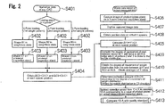
- the shapes of the glass plates C1, C2 and C3 shown in Fig. 1(b) are, as shown in the flowchart of Fig. 2 , obtainable by preparing first to third weight patterns of the design (CAD) data of a glass plate in a state that it is supported on a desired four-point supporting type actual measurement inspection stand (step (S) 401), calculating the design shape data (second design data B1, B2 and B3) of the glass plate A in weightless state based on the weight patterns (step (S) 402), and calculating the design shape data (third design data C1, C2 and C3) of the glass plate A in a state it is placed on a three-point supporting type universal inspection stand based on the design shape data of the glass plate A in weightless state (step (S) 403).
- CAD design
- Y1 indicates the glass plate Y1
- C1 indicates the glass plate C1
- Y2 indicates the glass plate Y2
- A indicates the glass plate A.
- position data Y1 1 to Y1 4 of a glass plate to be measured can be obtained by a step of capturing an image of a product glass plate supported on a three-point supporting type universal inspection stand (step (S) 406), a step of converting the captured image data into a numerical data (step (S) 407) and a step of obtaining position data on four supporting positions formed by virtual spacers (step (S) 408).
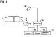
- Fig. 3 is an explanation view showing an embodiment of inspection apparatus.
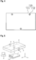
- a universal inspection stand 110 has a base 111 having a rectangular shape in top view and three rods 112 attached to the base so as to protrude upwardly from the base to support a rear surface of a glass plate 1 (refer to Fig. 4 ).
- the three rods 112 are disposed at respective apexes of a triangle on a top face of the base 111.
- a pad made of e.g. a resin is attached to the leading edge of each rod 112 to receive the glass plate 1.
- the inspection apparatus has a computer 120 constituted by a personal computer or a workstation, etc. for carrying out image processing of the captured image.
- a computer 120 constituted by a personal computer or a workstation, etc. for carrying out image processing of the captured image.
- the computer 120 various types of input/output devices are connected, and for example, the computer 120 is provided with a keyboard 122, a display 123 such as an LCD and a memory device 124 such as a hard disk drive.
- the memory device 124 the data of captured images and a program for carrying out image processing or drive control of the camera, etc. are stored.
- the present invention it is possible to measure the surface shape by a known method accommodated to an object to be measured.
- the method for measuring a surface shape is described by using as an example a method of actually measuring a surface shape of an object to be measured by a coordinate image capturing using an optical system and XYZ coordinate system.
- Fig. 5 is an explanation view showing the basic construction of a shape inspection apparatus.
- a plane light source 2 is disposed above a glass plate 1 having a mirror surface such as a glass for automobiles.
- a color pattern 3 is attached on an emission surface of the plane light source 2.
- one main camera and at least one sub color camera are disposed. These color cameras correspond to a camera 121 of Fig. 3 .
- the number of color cameras is not limited, but a main color camera 5 and a sub color cameras 6 and 7, namely total three color cameras, are employed in this example.
- the main camera 5 is disposed inside the plane light source 2, to capture a reflection image of the color pattern 3 projected on the glass plate 1 through a hole 4 opening in the color pattern 3.
- the sub color cameras 6 and 7 are disposed outside the plane light source 2, to capture images reflected by the glass plate 1.
- a computer 8 such as a personal computer is connected with the color cameras 5, 6 and 7 and analyzes reflected images captured by these cameras by a known image processing technique to obtain the shape of the glass plate 1.
- the optical system and the object to be measured are assumed to be placed in an XYZ coordinate system wherein Z axis is in the vertical direction. Sides of the plane light source 2 are assumed to be parallel with X axis and Y axis respectively.
- the XYZ coordinate system for describing the arrangement of the entire optical system is called as a global coordinate system and coordinates in the global coordinate system are called as global coordinates.
- the plane light source 2 one having a plurality of fluorescent lamps arranged in a casing, whose emission surface is covered by a glass plate, is employed.
- the color pattern 3 may be pasted on a surface of single cover glass or may be sandwiched by two cover glasses.
- the brightness of the plane light source 2 is preferably as uniform as possible, and for this purpose, arrangement of the fluorescent lamps in the casing is devised.
- the resin film to be used as the color pattern is preferably made of not a transparent material but a light-diffusion-transmitting material. By such a material, unevenness of brightness of the plane light source 2 is reduced.
- the color cameras 5, 6 and 7 are not particularly limited so long as they are of area camera types.
- Fig. 6 is a partial cross-sectional side view of the optical system by YZ plane, showing the relation of positions and view fields of three color cameras.
- the main color camera 5 points to vertically downward direction and captures a reflection image in the range of a view field 9.
- the sub color camera 6 captures a reflection image in the range of a view field 10, and is positioned so that a part of the view field 10 overlaps a part of the view field 9 on the glass plate 1.
- the sub color camera 7 captures a reflection image in the range of a view field 11, and is positioned so that a part of the view field 11 overlaps a part of the view field 9 on the glass plate 1.
- Fig. 7 is an explanation view of the color pattern 3.
- the color pattern 3 is constituted by a plurality of basic patterns 12 that are densely arranged so as not to overlap with each other. Accordingly, in the color pattern 3, the basic pattern 12 appears periodically in both vertical and lateral directions.
- Fig. 8 is a detailed explanation view of the basic pattern 12.
- the basic pattern 12 is constituted by 6x6 of fine square patterns, and each of the fine square patterns has any one of eight colors 12a to 12h.
- basic patterns 12 are associated with a local coordinate system having lateral and vertical directions.
- coordinates of a point in a basic pattern 12 are called as local coordinates.
- components of the local coordinates each takes a non-dimensional value of from 0 to 6. By these local coordinates, the position of optional point in the basic pattern 12 can be described.
- a lower left point is described as (0,0)
- the center point is described as (3,3)
- the upper right point is described as (6,6).
- Each component of local coordinate is not limited to an integer but the local coordinate can be described as e.g. (2.5,3.3).
- the position of a point in a basic pattern 12 is called as local coordinate.
- Eight colors constituting the basic pattern 12 are adjusted as follows in advance.
- Fig. 9 shows a red component, a green component and a blue component of an image of each of eight colors constituting the basic pattern captured by a color camera.
- the vertical axis of each graph shows the intensity of the color components.
- Colors 12a, 12b and 12c are adjusted so as not to contain blue component and have red components of the same intensity.
- the difference among the colors 12a, 12b and 12c resides in the intensity of green component.
- colors 12d, 12e and 12f are adjusted so as not to contain red component and have blue component of the same intensity.
- the difference among the colors 12d, 12e and 12f resides in the intensity of green component.
- a color 12g has red, green and blue components having the same strength
- a color 12h has red, green and blue components of no intensity.
- the intensities of red and blue components of the color 12g are the same as those of red components of the colors 12a, 12b and 12c and the same as blue components of the colors 12d, 12e and 12f.
- a stripe pattern 13 appears as shown in Fig. 10(a) .
- a stripe pattern 14 appears as shown in Fig. 10(b) .
- the stripe pattern 13 corresponds to the local coordinate in H direction
- the stripe pattern 14 corresponds to the local coordinate in V direction.
- the stripe patterns 13 and 14 preferably perpendicular to each other but they may be at another angle and the angle may be any angle so long as the directions are not parallel with each other.
- the shape data of the glass plate 1 can be obtained.
- step (S) 408) based on the above mentioned shape data of the glass plate 1, that is, based on the actual measurement shape data Y1 of the glass plate 1, the position data on the four supporting positions defined by virtual spacers is obtained as shown in Fig. 2 (step (S) 408).
- x is a suffix showing the supporting positions and x is 1, 2, 3 or 4.
- the degree of movement of weight distribution can be obtained from the ratio between ⁇ Y1 ( ⁇ Y1 1 to Y1 4 ) and ⁇ C2 ( ⁇ C2 1 to C2 4 ), and when Y1 is close to the pattern of C3, the degree of movement of weight distribution can be obtained from the ratio between ⁇ Y1 ( ⁇ Y1 1 to Y1 4 ) and ⁇ C3 ( ⁇ C3 1 to C3 4 ).
- the average r of the ratios of virtual four supporting positions to respective positions is obtained (step (S) 410).
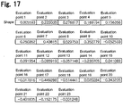
- the Table of Fig. 15 shows the ratio between ⁇ Y1 and ⁇ C3 at each of four points, and shows that the average r of the ratios is 53.1%.
- a correction amount R at each of the virtual supporting positions is obtained (step (S) 411).
- a value corresponding to a difference Y2-A between an actual measurement data Y2 on a desired actual measurement inspection stand of four-point supporting type (present inspection stand) and a glass plate having a design shape supported on a desired four-point supporting type actual measurement inspection stand, that is the first design data A, is calculated from the actual measurement data Y1 and the correction amount R that is r(C3-C1) or r(C2-C1) selected according to closeness of Y1 to the pattern of C2 or C3, that is, according to the unique weight pattern (step (S) 412).
- the method and program for inspecting the shape of a glass plate of this embodiment it is possible to inspect by predicting the shape of a glass plate on a four-point supporting type actual measurement inspection stand from the shape of a glass plate on a three-point supporting type universal inspection stand.
- the inspection positions and the number of the inspection positions may be appropriately determined considering the feature of the product shape or the quality specification of a glass plate to be inspected.
- the correction amount of R may take a positive value or a negative value. For example, Fig.
- the inspection standard in the present invention may be determined as a tolerable range of a numerical value showing the shape at predetermined inspection positions particularly in the thickness direction of the glass plate.
- the value corresponding to the difference Y2-A between the actual measurement data Y2 and the first design data A at the inspection positions thus obtained is compared with the inspection standard to judge the shape quality, and to output an inspection result.
- a quality standard that is for an inspection on a four-point type actual measurement inspection stand employed heretofore
- a measurement result obtained by measuring the shape of a glass plate placed on a three-point type universal inspection stand to judge the quality.
- the above mentioned quality inspection method of a glass plate is an inspection method requiring one main weight pattern and two sub weight patterns. There is a case of one main weight pattern (first weight pattern) and one sub weight pattern (second weight pattern) depending on the shape of the glass plate.
- first and second weight patterns of a design (CAD) data of a glass plate in a state that it is supported on a desired four-point supporting type actual measurement inspection stand is prepared (step (S) 501), a design shape data (second design data B1 and B2) of a glass plate A in weightless state is calculated from the first and second weight patterns (step (S) 502), and based on the design shape data of the glass plate A in weightless state, a design shape data (third design data C1 and C2) of the glass plate A in a state that it is placed on a three-point supporting type universal inspection stand is calculated (step (S) 503).
- CAD design
- a design shape data (second design data B1 and B2) of a glass plate A in weightless state is calculated from the first and second weight patterns (step (S) 502), and based on the design shape data of the glass plate A in weightless state, a design shape data (third design data C1 and C2) of the glass plate A in a state that
- step (S) 509) the degree of movement of weight distribution is obtained from the ratio between ⁇ Y1 ( ⁇ Y1 1 to Y1 4 ) and ⁇ C2 ( ⁇ C2 1 to C2 4 ), and the average r of four ratios at four virtual supporting positions is calculated (step (S) 509).
- the table of Fig. 19 and Fig. 20 show the ratio between ⁇ Y1 and ⁇ C2 at each of the four points, and show that the average r of the ratios is 0.505109.
- a correction amount r (C2-C1) of a weight distribution close to the pattern of C2 is obtained (step (S) 510).
- the above correction amount r (C2-C1) is subtracted from Y1-C1 to calculate a value corresponding to a difference Y2-A between a shape data Y2 on a desired four-point supporting type actual measurement inspection stand (present inspection stand) and the first design data A (step (S) 511).
- the shape inspection method for a glass plate of this embodiment it is possible to inspect by predicting the shape of a glass plate on a four-point supporting type actual measurement inspection stand from the shape of a glass plate on a three-point supporting type universal inspection stand.
- step (S) 511 the value corresponding to the difference Y2-A, obtained in step (S) 511, between the shape data Y2 of a glass plate and the first design data A is compared with a quality standard at predetermined inspection positions (step (S) 512).
- Fig. 19 shows that Y1 is always close to the pattern of C2 at each of the four supporting positions 1 to 4.
- the present invention provides a quality inspection method, an inspection apparatus and an inspection program suitable for shape inspection of an automotive window glass. Further, by calculating a virtual design data on an actual measurement inspection stand from a design data of a glass plate, it is possible to calculate the shape of the glass plate.
- the present invention is applicable not only to an inspection of window glass of an automotive application but also to those of railroad vehicles, airplanes, boats and buildings, etc. Further, the present invention is applicable not only to inspections of glass plates but also to inspections of other mirror surface objects, plate-shaped objects and lenses, etc.
Landscapes
- Physics & Mathematics (AREA)
- General Physics & Mathematics (AREA)
- Engineering & Computer Science (AREA)
- Computer Vision & Pattern Recognition (AREA)
- Length Measuring Devices With Unspecified Measuring Means (AREA)
- Length Measuring Devices By Optical Means (AREA)
Claims (6)
- Ein Verfahren zum Überprüfen der Qualität einer Glasplatte (1), das ein Verfahren zum Beurteilen der Qualität ausgehend von Entwurfsdaten einer Glasplatte (1) ist, die zur Verwendung als Fensterglas angebracht ist, und ausgehend von Formdaten einer gemessenen Glasplatte (1); wobei das Verfahren Folgendes umfasst:einen ersten Schritt (S401, S501) des Festlegens:von ersten Entwurfsdaten A, die die Form der angebrachten Glasplatte (1) darstellen,wobei ein erstes Gewichtsmuster ein Haupt-Gewichtsmuster ist, wobei Gewichte an vier tatsächlichen Messgewicht-Stützpunkten aufgebracht werden, die Gewicht-Stützpunkten eines tatsächlichen Messprüfstandes entsprechen, der gemäß der Form der angebrachten Glasplatte (1) ausgewählt wird, undwobei ein zweites Gewichtsmuster ein Unter-Gewichtsmuster ist, das mindestens eine Gewichtsverteilung beinhaltet, wobei Gewichte an nur drei Stützpunkten der vier Stützpunkte des tatsächlichen Prüfstands aufgebracht werden;einen zweiten Schritt (S402, S502) des Berechnens zweiter Entwurfsdaten B, nämlich B1 und B2, die den ersten bzw. zweiten Gewichtsmustern der Form der Glasplatte (1) im schwerelosen Zustand entsprechen, bei dem der Effekt der Flexion infolge der Schwerkraft ausgeschlossen ist, basierend auf den ersten Entwurfsdaten A und den ersten und zweiten Gewichtsmustern, sodass:die zweiten Entwurfsdaten B1 auf den ersten Entwurfsdaten A und dem ersten Gewichtsmuster basieren, unddie zweiten Entwurfsdaten B2 auf den ersten Entwurfsdaten A und dem zweiten Gewichtsmuster basieren;einen dritten Schritt (S403, S503) des Berechnens dritter Entwurfsdaten C, nämlich C1 und C2, die den ersten bzw. zweiten Gewichtsmustern der Form der Glasplatte (1) entsprechen, in einem Zustand, in dem die Glasplatte (1) virtuell auf einem Universalprüfstand (110) mit drei universellen Stützpunkten platziert ist, basierend auf den zweiten Entwurfsdaten B1 und B2, sodass:die dritten Entwurfsdaten C1 auf den zweiten Entwurfsdaten B1 basieren; unddie dritten Entwurfsdaten C2 auf den zweiten Entwurfsdaten B2 basieren;einen vierten Schritt des Berechnens der Positionsdaten C11 bis C14 und C21 bis C24 an den vier tatsächlichen Messgewichtstützpunkten der dritten Entwurfsdaten C entsprechend den Gewichtsmustern;einen fünften Schritt (S404, S504) des Berechnens eines Positionsvektors ΔC2 = C2x - C1x an jeder der virtuellen vier Stützpositionen, die den tatsächlichen vier Messgewichts-Stützpositionen aus den Positionsdaten C1x und C2x entsprechen, wobei x 1, 2, 3 oder 4 ist, was ein Suffix ist, das eine Stützposition darstellt;einen sechsten Schritt (S406, S506) des Messens von ersten tatsächlichen Messdaten Y1 der Form einer zu messenden, aus den Entwurfsdaten A hergestellten Glasplatte (1), wobei die genannte Glasplatte (1) auf einem Universalprüfstand (110) mit drei universellen Stützpunkten angeordnet ist;einen siebten Schritt (S408, S508) des Berechnens von Positionsdaten Y11 bis Y14 an den vier tatsächlichen Messgewichtstützpositionen in den ersten tatsächlichen Messdaten Y1;einen achten Schritt (S405, S505) des Berechnens eines Positionsvektors ΔY1 = Y1x - C1x aus den vier Positionsdaten C1x und den vier Positionsdaten Y1x;einen neunten Schritt (S410, S510) des Berechnens eines Mittelwerts aus einem Verhältnis r von ΔY1 zu ΔC2 an jeder der vier Positionsdaten;einen zehnten Schritt (S411, S511) des Erhaltens eines Formkorrekturbetrags R = r(C2 - C1) an jeder der vier Positionsdaten zum Erhalten von Positionsdaten der Messpunkte im Falle einer virtuellen Platzierung der zu prüfenden Glasplatte (1) auf den tatsächlichen Mess-Prüfstand, basierend auf den ersten tatsächlichen Messdaten Y1 und dem zweiten Gewichtsmuster;einen elften Schritt (S412, S512) des Berechnens eines Wertes, der einer Differenz Y2 - A entspricht, zwischen zweiten tatsächlichen Messdaten Y2 der Form der zu prüfenden, aus den Entwurfsdaten A hergestellten Glasplatte (1) und den ersten Entwurfsdaten A an einem gewünschten Prüfpunkt der zu prüfenden, auf dem tatsächlichen Messprüfstand platzierten Glasplatte (1), wobei der genannte Wert berechnet wird, durch Subtrahieren der Formkorrekturbetrag R von der Differenz Y1 - C1, die die man erhält durch Subtraktion der dritten Entwurfsdaten C1 der Glasplatte (1) von den ersten tatsächlichen Messdaten Y1; undeinen zwölften Schritt (S413, S513) des Beurteilens der Qualität der Glasplatte (1) auf der Grundlage des oben berechneten Werts, der Y2 - A entspricht, und eines Qualitätsstandards.
- Das Verfahren zum Prüfen der Qualität einer Glasplatte (1) nach Anspruch 1, wobei
im ersten Schritt (S401) ein drittes Gewichtsmuster, das ein Unter-Gewichtsmuster ist, wobei Gewichte auf nur drei Stützpunkte der vier Stützpunkte des tatsächlichen Prüfstands aufgebracht werden, zusätzlich eingestellt wird, wobei sich die Kombination von drei Stützpunkten des dritten Gewichtsmusters von demjenigen des zweiten Gewichtsmusters unterscheidet;
im zweiten (S402) Schritt zusätzlich zweite Entwurfsdaten B3 berechnet werden, wobei die zweiten Entwurfsdaten B3 auf den ersten Entwurfsdaten A und dem dritten Gewichtsmuster basieren;
im dritten Schritt (S403), auf der Grundlage der zweiten Entwurfsdaten B3, zusätzlich dritte Entwurfsdaten C3 berechnet werden;
im vierten Schritt zusätzlich die Positionsdaten C31 bis C34 in den dritten Entwurfsdaten C3 berechnet werden;
im fünften Schritt (S404) zusätzlich der Positionsvektor ΔC3 = C3x - C1x berechnet wird; und wobei
der neunte Schritt (S410) einen Schritt zum Vergleichen von ΔY1 mit ΔC2 und ΔC3 umfasst, um zu beurteilen, welches der zweiten Gewichtsmuster und der dritten Gewichtsmuster näher am Gewichtsmuster von Y1 liegt, basierend auf dem Grad der Übereinstimmung der Vorzeichen der Vektoren, um ein eindeutiges Gewichtsmuster zu beurteilen, und um das Vorzeichen des Vektors zurückzugeben, wobei das Verhältnis r als Durchschnitt eines Verhältnisses von ΔY1 zum Positionsvektor ΔC2 oder ΔC3 berechnet wird, der durch das eindeutige Gewichtsmuster bestimmt ist; und wobei
der zehnte Schritt (S411) einen Schritt umfasst des Erhaltens eines Formkorrekturbetrags R = r(C3 - C1) zum Erhalten von Positionsdaten der Messpunkte im Falle einer virtuellen Platzierung der zu prüfenden Glasplatte (1) auf den tatsächlichen Messprüfstand auf der Grundlage der ersten tatsächlichen Messdaten Y1 und des eindeutigen Gewichtsmusters; und wobei
der elfte Schritt das Auswählen des Korrekturbetrags R umfasst, der r(C3 - C1) oder r(C2 - C1) beträgt, ausgewählt gemäß der Nähe von Y1 zum Muster von C2 oder C3. - Das Verfahren zum Prüfen der Qualität einer Glasplatte (1) nach irgendeinem der Ansprüche 1 oder 2, wobei die Glasplatte (1) ein Kraftfahrzeugfensterglas ist.
- Ein Verfahren zum Messen der Form einer Glasplatte (1), das ein Verfahren zum Berechnen von Formdaten einer Glasplatte (1) ist, die auf einem tatsächlichen Messprüfstand platziert ist, unter Verwendung von Entwurfsdaten der Glasplatte (1), die zur Verwendung als Fensterglas angebracht ist; wobei das Verfahren Folgendes umfasst:einen ersten Schritt (S401, S501) des Festlegens:von ersten Entwurfsdaten A, die die Form der angebrachten Glasplatte (1) darstellen,wobei ein erstes Gewichtsmuster ein Haupt-Gewichtsmuster ist, wobei Gewichte an an vier tatsächlichen Messgewicht-Stützpunkten aufgebracht werden, die Gewicht-Stützpunkten eines tatsächlichen Messprüfstandes entsprechen, der gemäß der Form der angebrachten Glasplatte (1) ausgewählt wird, undwobei ein zweites Gewichtsmuster ein Unter-Gewichtsmuster ist, das mindestens eine Gewichtsverteilung beinhaltet, wobei Gewichte an nur drei Stützpunkten der vier Stützpunkte des tatsächlichen Prüfstands aufgebracht werden;einen zweiten Schritt (S402, S502) des Berechnens zweiter Entwurfsdaten B, nämlich B1 und B2, die den ersten bzw. zweiten Gewichtsmustern der Form der Glasplatte (1) im schwerelosen Zustand entsprechen, bei dem der Effekt der Flexion infolge der Schwerkraft ausgeschlossen ist, basierend auf den ersten Entwurfsdaten A und den ersten und zweiten Gewichtsmustern, sodass:die zweiten Entwurfsdaten B1 auf den ersten Entwurfsdaten A und dem ersten Gewichtsmuster basieren, unddie zweiten Entwurfsdaten B2 auf den ersten Entwurfsdaten A und dem zweiten Gewichtsmuster basieren;einen dritten Schritt (S403, S503) des Berechnens dritter Entwurfsdaten C, nämlich C1 und C2, die den ersten bzw. zweiten Gewichtsmustern der Form der Glasplatte (1) entsprechen, in einem Zustand, in dem die Glasplatte (1) virtuell auf einem Universalprüfstand (110) mit drei universellen Stützpunkten platziert ist, basierend auf den zweiten Entwurfsdaten B1 und B2, sodass:die dritten Entwurfsdaten C1 auf den zweiten Entwurfsdaten B1 basieren; unddie dritten Entwurfsdaten C2 auf den zweiten Entwurfsdaten B2 basieren;einen vierten Schritt des Berechnens der Positionsdaten C11 bis C14 und C21 bis C24 an den vier tatsächlichen Messgewichtstützpunkten der dritten Entwurfsdaten C entsprechend den Gewichtsmustern;einen fünften Schritt (S404, S504) des Berechnens eines Positionsvektors ΔC2 = C2x - C1x an jeder der virtuellen vier Stützpositionen, die den tatsächlichen vier Messgewichts-Stützpositionen aus den Positionsdaten C1x und C2x entsprechen, wobei x 1, 2, 3 oder 4 ist, was ein Suffix ist, das eine Stützposition darstellt;einen sechsten Schritt (S406, S506) des Messens von ersten tatsächlichen Messdaten Y1 einer zu messenden, aus den Entwurfsdaten A hergestellten Glasplatte (1), wobei die genannte Glasplatte (1) auf einem Universalprüfstand (110) mit drei universellen Stützpunkten angeordnet ist;einen siebten Schritt (S408, S508) des Berechnens von Positionsdaten Y11 bis Y14 an den vier tatsächlichen Messgewichtstützpositionen in den ersten tatsächlichen Messdaten Y1;einen achten Schritt (S405, S505) des Berechnens eines Positionsvektors ΔY1 = Y1x - C1x aus den vier Positionsdaten C1x und den vier Positionsdaten Y1x;einen neunten Schritt (S410, S510) des Berechnens eines Mittelwerts aus einem Verhältnis r von ΔY1 zu ΔC2 an jeder der vier Positionsdaten;einen zehnten Schritt (S411, S511) des Erhaltens eines Formkorrekturbetrags R = r(C2 - C1) an jeder der vier Positionsdaten zum Erhalten von Positionsdaten der Messpunkte im Falle einer virtuellen Platzierung der zu prüfenden Glasplatte (1) auf den tatsächlichen Mess-Prüfstand, basierend auf den ersten tatsächlichen Messdaten Y1 und dem zweiten Gewichtsmuster; undeinen elften Schritt (S412, S512) des Berechnens von zweiten tatsächlichen Messdaten Y2 der Form der zu prüfenden, aus den Entwurfsdaten A hergestellten Glasplatte (1) an einem gewünschten Prüfpunkt der zu prüfenden, auf dem tatsächlichen Messprüfstand platzierten Glasplatte (1), wobei der genannte Wert berechnet wird, durch Subtrahieren der dritten Entwurfsdaten C1 der Glasplatte (1), die virtuell mit dem ersten Gewichtsmuster platziert ist, von den ersten tatsächlichen Messdaten Y1, um die Differenz Y1 - C1 zu erhalten, wobei die ersten Entwurfsdaten A zur Differenz Y1 - C1 addiert werden und der Formkorrekturbetrag R von Y1 - C1 + A subtrahiert wird.
- Das Verfahren zum Messen der Form einer Glasplatte (1) nach Anspruch 4, wobei
im ersten Schritt (S401) ein drittes Gewichtsmuster, das ein Unter-Gewichtsmuster ist, wobei Gewichte auf nur drei Stützpunkte der vier Stützpunkte des tatsächlichen Prüfstands aufgebracht werden, zusätzlich eingestellt wird, wobei sich die Kombination von drei Stützpunkten des dritten Gewichtsmusters von demjenigen des zweiten Gewichtsmusters unterscheidet;
im zweiten Schritt (S402) zusätzlich zweite Entwurfsdaten B3 berechnet werden, wobei die zweiten Entwurfsdaten B2 auf den ersten Entwurfsdaten A und dem dritten Gewichtsmuster basieren;
im dritten Schritt (S403), auf der Grundlage der zweiten Entwurfsdaten B3 zusätzlich dritte Entwurfsdaten C3 berechnet werden;
im vierten Schritt zusätzlich die Positionsdaten C31 bis C34 in den dritten Entwurfsdaten C3 berechnet werden;
im fünften Schritt (S404) zusätzlich der Positionsvektor ΔC3 = C3x - C1x berechnet wird; und wobei
der neunte Schritt (S410) einen Schritt zum Vergleichen von ΔY1 mit ΔC2 und ΔC3 umfasst, um zu beurteilen, welches der zweiten Gewichtsmuster und der dritten Gewichtsmuster näher am Gewichtsmuster von Y1 liegt, basierend auf dem Grad der Übereinstimmung der Vorzeichen der Vektoren, um ein eindeutiges Gewichtsmuster zu beurteilen, und um das Vorzeichen des Vektors zurückzugeben, wobei das Verhältnis r als Durchschnitt eines Verhältnisses von ΔY1 zum Positionsvektor ΔC2 oder ΔC3 berechnet wird, der durch das eindeutige Gewichtsmuster bestimmt ist; und wobei
der zehnte Schritt (S411) ein Schritt ist des Erhaltens eines Formkorrekturbetrags R = r(C3 - C1) zum Erhalten von Positionsdaten der Messpunkte im Falle einer virtuellen Platzierung der zu prüfenden Glasplatte (1) auf den tatsächlichen Messprüfstand auf der Grundlage der ersten tatsächlichen Messdaten Y1 und des eindeutigen Gewichtsmusters; und im elften Schritt Auswählen des Korrekturbetrags R, der r(C3 - C1) oder r(C2 - C1) beträgt, wobei die Auswahl gemäß der Nähe von Y1 zum Muster von C2 oder C3 getroffen wird. - Ein Verfahren zur Erstellung einer Glasplatte (1), umfassend das Durchführen einer Rückkopplungs-Regelung unter Verwendung eines Bewertungsergebnisses des Verfahrens zum Prüfen der Qualität einer Glasplatte (1) gemäß Anspruch 1 oder 2.
Applications Claiming Priority (2)
| Application Number | Priority Date | Filing Date | Title |
|---|---|---|---|
| JP2009022839 | 2009-02-03 | ||
| PCT/JP2010/051528 WO2010090227A1 (ja) | 2009-02-03 | 2010-02-03 | ガラス板の品質検査方法及び品質検査プログラム |
Publications (3)
| Publication Number | Publication Date |
|---|---|
| EP2400262A1 EP2400262A1 (de) | 2011-12-28 |
| EP2400262A4 EP2400262A4 (de) | 2015-11-11 |
| EP2400262B1 true EP2400262B1 (de) | 2019-04-03 |
Family
ID=42542120
Family Applications (1)
| Application Number | Title | Priority Date | Filing Date |
|---|---|---|---|
| EP10738558.5A Active EP2400262B1 (de) | 2009-02-03 | 2010-02-03 | Verfahren zur überprüfung der qualität einer glasplatte, verfahren zur messung der form einer glasplatte und verfahren zur erstellung einer glasplatte |
Country Status (6)
| Country | Link |
|---|---|
| US (1) | US8793089B2 (de) |
| EP (1) | EP2400262B1 (de) |
| JP (1) | JP5403375B2 (de) |
| KR (1) | KR20110126583A (de) |
| CN (1) | CN102308181B (de) |
| WO (1) | WO2010090227A1 (de) |
Families Citing this family (5)
| Publication number | Priority date | Publication date | Assignee | Title |
|---|---|---|---|---|
| US8783066B2 (en) * | 2011-05-27 | 2014-07-22 | Corning Incorporated | Glass molding system and related apparatus and method |
| JP6325896B2 (ja) * | 2014-03-28 | 2018-05-16 | 株式会社キーエンス | 光学式座標測定装置 |
| CN109238118B (zh) * | 2018-11-06 | 2024-02-27 | 桂林电子科技大学 | 一种检测玻璃可装配性的检测系统及方法 |
| CN110006850B (zh) * | 2019-05-06 | 2019-11-15 | 金华东阳玖润信息科技有限公司 | 一种鉴别钢化玻璃真假的分析仪器 |
| JP7434686B2 (ja) * | 2019-12-27 | 2024-02-21 | 川崎重工業株式会社 | シート層の検査装置及び検査方法 |
Family Cites Families (8)
| Publication number | Priority date | Publication date | Assignee | Title |
|---|---|---|---|---|
| JPH04242103A (ja) | 1991-01-16 | 1992-08-28 | Asahi Glass Co Ltd | 板状材の曲率検査装置及び曲率検査方法 |
| JPH10279323A (ja) * | 1997-04-04 | 1998-10-20 | Asahi Glass Co Ltd | 板ガラスの曲げ量算出方法、その算出装置及び板ガラスの曲げ成形方法 |
| JP3661910B2 (ja) * | 1997-08-11 | 2005-06-22 | 旭硝子株式会社 | ガラス製品の基準面出し装置 |
| JP3966075B2 (ja) * | 2002-05-27 | 2007-08-29 | 日産自動車株式会社 | ワーク形状評価装置およびその方法ならびにそのプログラム |
| WO2007010875A1 (ja) * | 2005-07-15 | 2007-01-25 | Asahi Glass Company, Limited | 形状検査方法および装置 |
| US7589844B2 (en) * | 2005-07-15 | 2009-09-15 | Asahi Glass Company, Limited | Shape inspection method and apparatus |
| DE102005050882B4 (de) * | 2005-10-21 | 2008-04-30 | Isra Vision Systems Ag | System und Verfahren zur optischen Inspektion von Glasscheiben |
| JP5307363B2 (ja) | 2007-07-17 | 2013-10-02 | 邦夫 佐々木 | 砕砂製造装置 |
-
2010
- 2010-02-03 KR KR1020117010040A patent/KR20110126583A/ko not_active Withdrawn
- 2010-02-03 WO PCT/JP2010/051528 patent/WO2010090227A1/ja not_active Ceased
- 2010-02-03 EP EP10738558.5A patent/EP2400262B1/de active Active
- 2010-02-03 CN CN201080006557.6A patent/CN102308181B/zh not_active Expired - Fee Related
- 2010-02-03 JP JP2010549494A patent/JP5403375B2/ja not_active Expired - Fee Related
-
2011
- 2011-08-03 US US13/197,298 patent/US8793089B2/en not_active Expired - Fee Related
Non-Patent Citations (1)
| Title |
|---|
| None * |
Also Published As
| Publication number | Publication date |
|---|---|
| EP2400262A4 (de) | 2015-11-11 |
| EP2400262A1 (de) | 2011-12-28 |
| CN102308181A (zh) | 2012-01-04 |
| US20110288803A1 (en) | 2011-11-24 |
| KR20110126583A (ko) | 2011-11-23 |
| JPWO2010090227A1 (ja) | 2012-08-09 |
| US8793089B2 (en) | 2014-07-29 |
| WO2010090227A1 (ja) | 2010-08-12 |
| JP5403375B2 (ja) | 2014-01-29 |
| CN102308181B (zh) | 2014-04-09 |
Similar Documents
| Publication | Publication Date | Title |
|---|---|---|
| US7589844B2 (en) | Shape inspection method and apparatus | |
| EP1906139B1 (de) | Formuntersuchungsverfahren und -einrichtung | |
| KR101004473B1 (ko) | 면왜곡의 측정장치 및 방법 | |
| CN104769411B (zh) | 机动车用部件的外板的动态拉伸刚性的测定方法及测定装置 | |
| US8793089B2 (en) | Method for inspecting quality of glass plate | |
| CN105842885B (zh) | 一种液晶屏缺陷分层定位方法及装置 | |
| CN100462789C (zh) | 液晶显示器用玻璃基板及其基样玻璃制造方法和检测装置 | |
| EP3314236B1 (de) | System und verfahren zur messung der reflektierten verzerrung in konturierten glasscheiben | |
| EP3026632A2 (de) | Verbesserungen an oder im zusammenhang mit digitalen bildkorrelationssystemen | |
| EP3314237B1 (de) | System und verfahren zur entwicklung dreidimensionaler oberflächeninformationen entsprechend einer konturierten glasscheibe | |
| CN111556953B (zh) | 用于测量多个待评估材料的中凹表面和参考材料的中凹表面之间的几何偏差的方法 | |
| CN101840078B (zh) | 水波纹级别测试方法 | |
| CN102507446A (zh) | 一种透光玻璃光学角偏差的检测方法 | |
| US11733685B2 (en) | Surface inspection method using mold surface inspection device | |
| CN210953862U (zh) | 一种液晶屏划痕检测装置 | |
| CN108986721A (zh) | 一种用于显示面板检测的检测图形生成方法 | |
| CN121298197A (zh) | 车载hud光学性能综合检测方法及装置 | |
| JPH0623992B2 (ja) | 板ガラスの検査方法 | |
| CN212482419U (zh) | 一种玻璃检测设备 | |
| CN120741488B (zh) | 一种复合材料板件质量检测系统和方法 | |
| WO2022115928A1 (pt) | Métodos e sistemas para a inspeção de qualidade de materiais e de superfícies tridimensionais em ambiente virtual | |
| CN119413622A (zh) | 一种易采集dic数据的板材flc曲线测试用样片套组及采集方法 | |
| CN119534455A (zh) | 浮法玻璃的缺陷检测方法及装置 | |
| JP2013125013A (ja) | フォトスペーサー高さ検査方法及び装置 |
Legal Events
| Date | Code | Title | Description |
|---|---|---|---|
| PUAI | Public reference made under article 153(3) epc to a published international application that has entered the european phase |
Free format text: ORIGINAL CODE: 0009012 |
|
| 17P | Request for examination filed |
Effective date: 20110811 |
|
| AK | Designated contracting states |
Kind code of ref document: A1 Designated state(s): AT BE BG CH CY CZ DE DK EE ES FI FR GB GR HR HU IE IS IT LI LT LU LV MC MK MT NL NO PL PT RO SE SI SK SM TR |
|
| DAX | Request for extension of the european patent (deleted) | ||
| RA4 | Supplementary search report drawn up and despatched (corrected) |
Effective date: 20151009 |
|
| RIC1 | Information provided on ipc code assigned before grant |
Ipc: G01B 11/25 20060101ALI20151005BHEP Ipc: G01B 11/16 20060101ALI20151005BHEP Ipc: G01B 21/20 20060101AFI20151005BHEP |
|
| GRAP | Despatch of communication of intention to grant a patent |
Free format text: ORIGINAL CODE: EPIDOSNIGR1 |
|
| STAA | Information on the status of an ep patent application or granted ep patent |
Free format text: STATUS: GRANT OF PATENT IS INTENDED |
|
| RAP1 | Party data changed (applicant data changed or rights of an application transferred) |
Owner name: AGC INC. |
|
| INTG | Intention to grant announced |
Effective date: 20180911 |
|
| GRAJ | Information related to disapproval of communication of intention to grant by the applicant or resumption of examination proceedings by the epo deleted |
Free format text: ORIGINAL CODE: EPIDOSDIGR1 |
|
| GRAP | Despatch of communication of intention to grant a patent |
Free format text: ORIGINAL CODE: EPIDOSNIGR1 |
|
| INTG | Intention to grant announced |
Effective date: 20181024 |
|
| GRAS | Grant fee paid |
Free format text: ORIGINAL CODE: EPIDOSNIGR3 |
|
| GRAA | (expected) grant |
Free format text: ORIGINAL CODE: 0009210 |
|
| STAA | Information on the status of an ep patent application or granted ep patent |
Free format text: STATUS: THE PATENT HAS BEEN GRANTED |
|
| AK | Designated contracting states |
Kind code of ref document: B1 Designated state(s): AT BE BG CH CY CZ DE DK EE ES FI FR GB GR HR HU IE IS IT LI LT LU LV MC MK MT NL NO PL PT RO SE SI SK SM TR |
|
| REG | Reference to a national code |
Ref country code: GB Ref legal event code: FG4D |
|
| REG | Reference to a national code |
Ref country code: CH Ref legal event code: EP Ref country code: AT Ref legal event code: REF Ref document number: 1116279 Country of ref document: AT Kind code of ref document: T Effective date: 20190415 |
|
| REG | Reference to a national code |
Ref country code: DE Ref legal event code: R096 Ref document number: 602010057992 Country of ref document: DE |
|
| REG | Reference to a national code |
Ref country code: IE Ref legal event code: FG4D |
|
| REG | Reference to a national code |
Ref country code: NL Ref legal event code: MP Effective date: 20190403 |
|
| REG | Reference to a national code |
Ref country code: LT Ref legal event code: MG4D |
|
| REG | Reference to a national code |
Ref country code: AT Ref legal event code: MK05 Ref document number: 1116279 Country of ref document: AT Kind code of ref document: T Effective date: 20190403 |
|
| PG25 | Lapsed in a contracting state [announced via postgrant information from national office to epo] |
Ref country code: NL Free format text: LAPSE BECAUSE OF FAILURE TO SUBMIT A TRANSLATION OF THE DESCRIPTION OR TO PAY THE FEE WITHIN THE PRESCRIBED TIME-LIMIT Effective date: 20190403 |
|
| PG25 | Lapsed in a contracting state [announced via postgrant information from national office to epo] |
Ref country code: FI Free format text: LAPSE BECAUSE OF FAILURE TO SUBMIT A TRANSLATION OF THE DESCRIPTION OR TO PAY THE FEE WITHIN THE PRESCRIBED TIME-LIMIT Effective date: 20190403 Ref country code: PT Free format text: LAPSE BECAUSE OF FAILURE TO SUBMIT A TRANSLATION OF THE DESCRIPTION OR TO PAY THE FEE WITHIN THE PRESCRIBED TIME-LIMIT Effective date: 20190803 Ref country code: NO Free format text: LAPSE BECAUSE OF FAILURE TO SUBMIT A TRANSLATION OF THE DESCRIPTION OR TO PAY THE FEE WITHIN THE PRESCRIBED TIME-LIMIT Effective date: 20190703 Ref country code: SE Free format text: LAPSE BECAUSE OF FAILURE TO SUBMIT A TRANSLATION OF THE DESCRIPTION OR TO PAY THE FEE WITHIN THE PRESCRIBED TIME-LIMIT Effective date: 20190403 Ref country code: HR Free format text: LAPSE BECAUSE OF FAILURE TO SUBMIT A TRANSLATION OF THE DESCRIPTION OR TO PAY THE FEE WITHIN THE PRESCRIBED TIME-LIMIT Effective date: 20190403 Ref country code: LT Free format text: LAPSE BECAUSE OF FAILURE TO SUBMIT A TRANSLATION OF THE DESCRIPTION OR TO PAY THE FEE WITHIN THE PRESCRIBED TIME-LIMIT Effective date: 20190403 Ref country code: ES Free format text: LAPSE BECAUSE OF FAILURE TO SUBMIT A TRANSLATION OF THE DESCRIPTION OR TO PAY THE FEE WITHIN THE PRESCRIBED TIME-LIMIT Effective date: 20190403 Ref country code: CZ Free format text: LAPSE BECAUSE OF FAILURE TO SUBMIT A TRANSLATION OF THE DESCRIPTION OR TO PAY THE FEE WITHIN THE PRESCRIBED TIME-LIMIT Effective date: 20190403 |
|
| PG25 | Lapsed in a contracting state [announced via postgrant information from national office to epo] |
Ref country code: LV Free format text: LAPSE BECAUSE OF FAILURE TO SUBMIT A TRANSLATION OF THE DESCRIPTION OR TO PAY THE FEE WITHIN THE PRESCRIBED TIME-LIMIT Effective date: 20190403 Ref country code: BG Free format text: LAPSE BECAUSE OF FAILURE TO SUBMIT A TRANSLATION OF THE DESCRIPTION OR TO PAY THE FEE WITHIN THE PRESCRIBED TIME-LIMIT Effective date: 20190703 Ref country code: PL Free format text: LAPSE BECAUSE OF FAILURE TO SUBMIT A TRANSLATION OF THE DESCRIPTION OR TO PAY THE FEE WITHIN THE PRESCRIBED TIME-LIMIT Effective date: 20190403 Ref country code: GR Free format text: LAPSE BECAUSE OF FAILURE TO SUBMIT A TRANSLATION OF THE DESCRIPTION OR TO PAY THE FEE WITHIN THE PRESCRIBED TIME-LIMIT Effective date: 20190704 |
|
| PG25 | Lapsed in a contracting state [announced via postgrant information from national office to epo] |
Ref country code: IS Free format text: LAPSE BECAUSE OF FAILURE TO SUBMIT A TRANSLATION OF THE DESCRIPTION OR TO PAY THE FEE WITHIN THE PRESCRIBED TIME-LIMIT Effective date: 20190803 Ref country code: AT Free format text: LAPSE BECAUSE OF FAILURE TO SUBMIT A TRANSLATION OF THE DESCRIPTION OR TO PAY THE FEE WITHIN THE PRESCRIBED TIME-LIMIT Effective date: 20190403 |
|
| REG | Reference to a national code |
Ref country code: DE Ref legal event code: R097 Ref document number: 602010057992 Country of ref document: DE |
|
| PG25 | Lapsed in a contracting state [announced via postgrant information from national office to epo] |
Ref country code: RO Free format text: LAPSE BECAUSE OF FAILURE TO SUBMIT A TRANSLATION OF THE DESCRIPTION OR TO PAY THE FEE WITHIN THE PRESCRIBED TIME-LIMIT Effective date: 20190403 Ref country code: DK Free format text: LAPSE BECAUSE OF FAILURE TO SUBMIT A TRANSLATION OF THE DESCRIPTION OR TO PAY THE FEE WITHIN THE PRESCRIBED TIME-LIMIT Effective date: 20190403 Ref country code: EE Free format text: LAPSE BECAUSE OF FAILURE TO SUBMIT A TRANSLATION OF THE DESCRIPTION OR TO PAY THE FEE WITHIN THE PRESCRIBED TIME-LIMIT Effective date: 20190403 Ref country code: SK Free format text: LAPSE BECAUSE OF FAILURE TO SUBMIT A TRANSLATION OF THE DESCRIPTION OR TO PAY THE FEE WITHIN THE PRESCRIBED TIME-LIMIT Effective date: 20190403 |
|
| PLBE | No opposition filed within time limit |
Free format text: ORIGINAL CODE: 0009261 |
|
| STAA | Information on the status of an ep patent application or granted ep patent |
Free format text: STATUS: NO OPPOSITION FILED WITHIN TIME LIMIT |
|
| PG25 | Lapsed in a contracting state [announced via postgrant information from national office to epo] |
Ref country code: IT Free format text: LAPSE BECAUSE OF FAILURE TO SUBMIT A TRANSLATION OF THE DESCRIPTION OR TO PAY THE FEE WITHIN THE PRESCRIBED TIME-LIMIT Effective date: 20190403 Ref country code: SM Free format text: LAPSE BECAUSE OF FAILURE TO SUBMIT A TRANSLATION OF THE DESCRIPTION OR TO PAY THE FEE WITHIN THE PRESCRIBED TIME-LIMIT Effective date: 20190403 |
|
| 26N | No opposition filed |
Effective date: 20200106 |
|
| PG25 | Lapsed in a contracting state [announced via postgrant information from national office to epo] |
Ref country code: TR Free format text: LAPSE BECAUSE OF FAILURE TO SUBMIT A TRANSLATION OF THE DESCRIPTION OR TO PAY THE FEE WITHIN THE PRESCRIBED TIME-LIMIT Effective date: 20190403 |
|
| PGFP | Annual fee paid to national office [announced via postgrant information from national office to epo] |
Ref country code: DE Payment date: 20200219 Year of fee payment: 11 |
|
| PG25 | Lapsed in a contracting state [announced via postgrant information from national office to epo] |
Ref country code: SI Free format text: LAPSE BECAUSE OF FAILURE TO SUBMIT A TRANSLATION OF THE DESCRIPTION OR TO PAY THE FEE WITHIN THE PRESCRIBED TIME-LIMIT Effective date: 20190403 |
|
| REG | Reference to a national code |
Ref country code: CH Ref legal event code: PL |
|
| GBPC | Gb: european patent ceased through non-payment of renewal fee |
Effective date: 20200203 |
|
| REG | Reference to a national code |
Ref country code: BE Ref legal event code: MM Effective date: 20200229 |
|
| PG25 | Lapsed in a contracting state [announced via postgrant information from national office to epo] |
Ref country code: LU Free format text: LAPSE BECAUSE OF NON-PAYMENT OF DUE FEES Effective date: 20200203 Ref country code: MC Free format text: LAPSE BECAUSE OF FAILURE TO SUBMIT A TRANSLATION OF THE DESCRIPTION OR TO PAY THE FEE WITHIN THE PRESCRIBED TIME-LIMIT Effective date: 20190403 |
|
| PG25 | Lapsed in a contracting state [announced via postgrant information from national office to epo] |
Ref country code: LI Free format text: LAPSE BECAUSE OF NON-PAYMENT OF DUE FEES Effective date: 20200229 Ref country code: CH Free format text: LAPSE BECAUSE OF NON-PAYMENT OF DUE FEES Effective date: 20200229 |
|
| PG25 | Lapsed in a contracting state [announced via postgrant information from national office to epo] |
Ref country code: GB Free format text: LAPSE BECAUSE OF NON-PAYMENT OF DUE FEES Effective date: 20200203 Ref country code: FR Free format text: LAPSE BECAUSE OF NON-PAYMENT OF DUE FEES Effective date: 20200229 Ref country code: IE Free format text: LAPSE BECAUSE OF NON-PAYMENT OF DUE FEES Effective date: 20200203 |
|
| PG25 | Lapsed in a contracting state [announced via postgrant information from national office to epo] |
Ref country code: BE Free format text: LAPSE BECAUSE OF NON-PAYMENT OF DUE FEES Effective date: 20200229 |
|
| REG | Reference to a national code |
Ref country code: DE Ref legal event code: R119 Ref document number: 602010057992 Country of ref document: DE |
|
| PG25 | Lapsed in a contracting state [announced via postgrant information from national office to epo] |
Ref country code: DE Free format text: LAPSE BECAUSE OF NON-PAYMENT OF DUE FEES Effective date: 20210901 |
|
| PG25 | Lapsed in a contracting state [announced via postgrant information from national office to epo] |
Ref country code: MT Free format text: LAPSE BECAUSE OF FAILURE TO SUBMIT A TRANSLATION OF THE DESCRIPTION OR TO PAY THE FEE WITHIN THE PRESCRIBED TIME-LIMIT Effective date: 20190403 Ref country code: CY Free format text: LAPSE BECAUSE OF FAILURE TO SUBMIT A TRANSLATION OF THE DESCRIPTION OR TO PAY THE FEE WITHIN THE PRESCRIBED TIME-LIMIT Effective date: 20190403 |
|
| PG25 | Lapsed in a contracting state [announced via postgrant information from national office to epo] |
Ref country code: MK Free format text: LAPSE BECAUSE OF FAILURE TO SUBMIT A TRANSLATION OF THE DESCRIPTION OR TO PAY THE FEE WITHIN THE PRESCRIBED TIME-LIMIT Effective date: 20190403 |