EP2399739A1 - Procédé pour produire un composite à base de résine - Google Patents
Procédé pour produire un composite à base de résine Download PDFInfo
- Publication number
- EP2399739A1 EP2399739A1 EP10743663A EP10743663A EP2399739A1 EP 2399739 A1 EP2399739 A1 EP 2399739A1 EP 10743663 A EP10743663 A EP 10743663A EP 10743663 A EP10743663 A EP 10743663A EP 2399739 A1 EP2399739 A1 EP 2399739A1
- Authority
- EP
- European Patent Office
- Prior art keywords
- resin
- sheet
- based composite
- conductive
- conductive layer
- Prior art date
- Legal status (The legal status is an assumption and is not a legal conclusion. Google has not performed a legal analysis and makes no representation as to the accuracy of the status listed.)
- Withdrawn
Links
Images
Classifications
-
- B—PERFORMING OPERATIONS; TRANSPORTING
- B32—LAYERED PRODUCTS
- B32B—LAYERED PRODUCTS, i.e. PRODUCTS BUILT-UP OF STRATA OF FLAT OR NON-FLAT, e.g. CELLULAR OR HONEYCOMB, FORM
- B32B27/00—Layered products comprising a layer of synthetic resin
- B32B27/04—Layered products comprising a layer of synthetic resin as impregnant, bonding, or embedding substance
-
- B—PERFORMING OPERATIONS; TRANSPORTING
- B32—LAYERED PRODUCTS
- B32B—LAYERED PRODUCTS, i.e. PRODUCTS BUILT-UP OF STRATA OF FLAT OR NON-FLAT, e.g. CELLULAR OR HONEYCOMB, FORM
- B32B27/00—Layered products comprising a layer of synthetic resin
- B32B27/06—Layered products comprising a layer of synthetic resin as the main or only constituent of a layer, which is next to another layer of the same or of a different material
- B32B27/08—Layered products comprising a layer of synthetic resin as the main or only constituent of a layer, which is next to another layer of the same or of a different material of synthetic resin
-
- B—PERFORMING OPERATIONS; TRANSPORTING
- B32—LAYERED PRODUCTS
- B32B—LAYERED PRODUCTS, i.e. PRODUCTS BUILT-UP OF STRATA OF FLAT OR NON-FLAT, e.g. CELLULAR OR HONEYCOMB, FORM
- B32B27/00—Layered products comprising a layer of synthetic resin
- B32B27/12—Layered products comprising a layer of synthetic resin next to a fibrous or filamentary layer
-
- B—PERFORMING OPERATIONS; TRANSPORTING
- B32—LAYERED PRODUCTS
- B32B—LAYERED PRODUCTS, i.e. PRODUCTS BUILT-UP OF STRATA OF FLAT OR NON-FLAT, e.g. CELLULAR OR HONEYCOMB, FORM
- B32B27/00—Layered products comprising a layer of synthetic resin
- B32B27/18—Layered products comprising a layer of synthetic resin characterised by the use of special additives
- B32B27/20—Layered products comprising a layer of synthetic resin characterised by the use of special additives using fillers, pigments, thixotroping agents
-
- B—PERFORMING OPERATIONS; TRANSPORTING
- B32—LAYERED PRODUCTS
- B32B—LAYERED PRODUCTS, i.e. PRODUCTS BUILT-UP OF STRATA OF FLAT OR NON-FLAT, e.g. CELLULAR OR HONEYCOMB, FORM
- B32B27/00—Layered products comprising a layer of synthetic resin
- B32B27/30—Layered products comprising a layer of synthetic resin comprising vinyl (co)polymers; comprising acrylic (co)polymers
- B32B27/308—Layered products comprising a layer of synthetic resin comprising vinyl (co)polymers; comprising acrylic (co)polymers comprising acrylic (co)polymers
-
- B—PERFORMING OPERATIONS; TRANSPORTING
- B32—LAYERED PRODUCTS
- B32B—LAYERED PRODUCTS, i.e. PRODUCTS BUILT-UP OF STRATA OF FLAT OR NON-FLAT, e.g. CELLULAR OR HONEYCOMB, FORM
- B32B27/00—Layered products comprising a layer of synthetic resin
- B32B27/38—Layered products comprising a layer of synthetic resin comprising epoxy resins
-
- B—PERFORMING OPERATIONS; TRANSPORTING
- B32—LAYERED PRODUCTS
- B32B—LAYERED PRODUCTS, i.e. PRODUCTS BUILT-UP OF STRATA OF FLAT OR NON-FLAT, e.g. CELLULAR OR HONEYCOMB, FORM
- B32B27/00—Layered products comprising a layer of synthetic resin
- B32B27/40—Layered products comprising a layer of synthetic resin comprising polyurethanes
-
- B—PERFORMING OPERATIONS; TRANSPORTING
- B32—LAYERED PRODUCTS
- B32B—LAYERED PRODUCTS, i.e. PRODUCTS BUILT-UP OF STRATA OF FLAT OR NON-FLAT, e.g. CELLULAR OR HONEYCOMB, FORM
- B32B27/00—Layered products comprising a layer of synthetic resin
- B32B27/42—Layered products comprising a layer of synthetic resin comprising condensation resins of aldehydes, e.g. with phenols, ureas or melamines
-
- B—PERFORMING OPERATIONS; TRANSPORTING
- B32—LAYERED PRODUCTS
- B32B—LAYERED PRODUCTS, i.e. PRODUCTS BUILT-UP OF STRATA OF FLAT OR NON-FLAT, e.g. CELLULAR OR HONEYCOMB, FORM
- B32B7/00—Layered products characterised by the relation between layers; Layered products characterised by the relative orientation of features between layers, or by the relative values of a measurable parameter between layers, i.e. products comprising layers having different physical, chemical or physicochemical properties; Layered products characterised by the interconnection of layers
- B32B7/04—Interconnection of layers
- B32B7/12—Interconnection of layers using interposed adhesives or interposed materials with bonding properties
-
- B—PERFORMING OPERATIONS; TRANSPORTING
- B64—AIRCRAFT; AVIATION; COSMONAUTICS
- B64D—EQUIPMENT FOR FITTING IN OR TO AIRCRAFT; FLIGHT SUITS; PARACHUTES; ARRANGEMENTS OR MOUNTING OF POWER PLANTS OR PROPULSION TRANSMISSIONS IN AIRCRAFT
- B64D45/00—Aircraft indicators or protectors not otherwise provided for
- B64D45/02—Lightning protectors; Static dischargers
-
- B—PERFORMING OPERATIONS; TRANSPORTING
- B32—LAYERED PRODUCTS
- B32B—LAYERED PRODUCTS, i.e. PRODUCTS BUILT-UP OF STRATA OF FLAT OR NON-FLAT, e.g. CELLULAR OR HONEYCOMB, FORM
- B32B2255/00—Coating on the layer surface
- B32B2255/10—Coating on the layer surface on synthetic resin layer or on natural or synthetic rubber layer
-
- B—PERFORMING OPERATIONS; TRANSPORTING
- B32—LAYERED PRODUCTS
- B32B—LAYERED PRODUCTS, i.e. PRODUCTS BUILT-UP OF STRATA OF FLAT OR NON-FLAT, e.g. CELLULAR OR HONEYCOMB, FORM
- B32B2255/00—Coating on the layer surface
- B32B2255/20—Inorganic coating
- B32B2255/205—Metallic coating
-
- B—PERFORMING OPERATIONS; TRANSPORTING
- B32—LAYERED PRODUCTS
- B32B—LAYERED PRODUCTS, i.e. PRODUCTS BUILT-UP OF STRATA OF FLAT OR NON-FLAT, e.g. CELLULAR OR HONEYCOMB, FORM
- B32B2262/00—Composition or structural features of fibres which form a fibrous or filamentary layer or are present as additives
- B32B2262/10—Inorganic fibres
- B32B2262/101—Glass fibres
-
- B—PERFORMING OPERATIONS; TRANSPORTING
- B32—LAYERED PRODUCTS
- B32B—LAYERED PRODUCTS, i.e. PRODUCTS BUILT-UP OF STRATA OF FLAT OR NON-FLAT, e.g. CELLULAR OR HONEYCOMB, FORM
- B32B2262/00—Composition or structural features of fibres which form a fibrous or filamentary layer or are present as additives
- B32B2262/10—Inorganic fibres
- B32B2262/106—Carbon fibres, e.g. graphite fibres
-
- B—PERFORMING OPERATIONS; TRANSPORTING
- B32—LAYERED PRODUCTS
- B32B—LAYERED PRODUCTS, i.e. PRODUCTS BUILT-UP OF STRATA OF FLAT OR NON-FLAT, e.g. CELLULAR OR HONEYCOMB, FORM
- B32B2264/00—Composition or properties of particles which form a particulate layer or are present as additives
- B32B2264/10—Inorganic particles
- B32B2264/105—Metal
-
- B—PERFORMING OPERATIONS; TRANSPORTING
- B32—LAYERED PRODUCTS
- B32B—LAYERED PRODUCTS, i.e. PRODUCTS BUILT-UP OF STRATA OF FLAT OR NON-FLAT, e.g. CELLULAR OR HONEYCOMB, FORM
- B32B2307/00—Properties of the layers or laminate
- B32B2307/20—Properties of the layers or laminate having particular electrical or magnetic properties, e.g. piezoelectric
- B32B2307/202—Conductive
-
- B—PERFORMING OPERATIONS; TRANSPORTING
- B32—LAYERED PRODUCTS
- B32B—LAYERED PRODUCTS, i.e. PRODUCTS BUILT-UP OF STRATA OF FLAT OR NON-FLAT, e.g. CELLULAR OR HONEYCOMB, FORM
- B32B2307/00—Properties of the layers or laminate
- B32B2307/50—Properties of the layers or laminate having particular mechanical properties
- B32B2307/546—Flexural strength; Flexion stiffness
-
- B—PERFORMING OPERATIONS; TRANSPORTING
- B32—LAYERED PRODUCTS
- B32B—LAYERED PRODUCTS, i.e. PRODUCTS BUILT-UP OF STRATA OF FLAT OR NON-FLAT, e.g. CELLULAR OR HONEYCOMB, FORM
- B32B2307/00—Properties of the layers or laminate
- B32B2307/50—Properties of the layers or laminate having particular mechanical properties
- B32B2307/582—Tearability
- B32B2307/5825—Tear resistant
-
- B—PERFORMING OPERATIONS; TRANSPORTING
- B32—LAYERED PRODUCTS
- B32B—LAYERED PRODUCTS, i.e. PRODUCTS BUILT-UP OF STRATA OF FLAT OR NON-FLAT, e.g. CELLULAR OR HONEYCOMB, FORM
- B32B2307/00—Properties of the layers or laminate
- B32B2307/70—Other properties
- B32B2307/71—Resistive to light or to UV
-
- B—PERFORMING OPERATIONS; TRANSPORTING
- B32—LAYERED PRODUCTS
- B32B—LAYERED PRODUCTS, i.e. PRODUCTS BUILT-UP OF STRATA OF FLAT OR NON-FLAT, e.g. CELLULAR OR HONEYCOMB, FORM
- B32B2307/00—Properties of the layers or laminate
- B32B2307/70—Other properties
- B32B2307/732—Dimensional properties
Definitions
- the present invention relates to a method for producing a resin-based composite having conductivity.
- Resin-based composites such as fiber-reinforced resins are lightweight and have high strength, and are therefore widely used as structural members for aircraft, automobiles and ships and the like. These types of resin-based composites comprise a resin of low conductivity as a matrix, and therefore when they are used, for example, for the main wing structure of an aircraft, conductivity must be imparted to the surface of the composite in order to provide lightning resistance.
- the method for imparting conductivity to the surface of the composite generally employs a technique in which a copper foil is laminated to the surface of the composite by thermally bonding the copper foil at the same time as the formation of the composite (for example, see PTL 1) .
- resin-based composites that use a copper foil as a lightning-resistant layer have also suffered from a problem of poor workability, and are prone to the generation of burrs upon cutting or perforation.
- the present invention has been developed in light of these circumstances, and provides a method for producing, with good workability, a composite that exhibits excellent adhesion to a resin-based composite and has a lightning-resistant layer.
- the present invention provides a method for producing a resin-based composite, the method comprising a step of forming a laminate by sequentially laminating, on a first resin sheet comprising mainly a fiber-reinforced resin, a conductive layer formed from a resin containing a metal powder, and a second resin sheet comprising mainly a fiber-reinforced resin, and a step of forming a resin-based composite by baking the laminate to bond the first resin sheet, the conductive layer and the second resin sheet.
- the present invention provides a method for producing a resin-based composite, the method comprising a step of forming a laminate by laminating a conductive layer formed from a resin containing a metal powder to one surface of a first resin sheet comprising mainly a fiber-reinforced resin, and laminating a second resin sheet comprising mainly a fiber-reinforced resin to the surface on the opposite side to the surface on which the conductive layer is formed, and a step of forming a resin-based composite by baking the laminate to bond the first resin sheet, the conductive layer and the second resin sheet.
- the above-mentioned conductive layer contains a resin as the main component, the difference in the coefficients of thermal expansion for the conductive layer and the fiber-reinforced resin sheets is small. As a result, the residual stress following bonding is reduced, and therefore a resin-based composite that exhibits excellent adhesion to a fiber-reinforced resin sheet and has a lightning-resistant layer can be obtained. Further, because the handling properties improve, the conductive layer can be formed across a broad surface area of the fiber-reinforced resin sheet surface.
- the metal powder is a copper powder or silver powder, then a conductive layer with good conductivity can be achieved, which is preferable.
- a resin-based composite that exhibits excellent adhesion to a fiber-reinforced resin sheet and has a lightning-resistant layer can be obtained. Further, because the handling properties improve, the conductive layer can be formed across a broad surface area of the fiber-reinforced resin sheet surface.
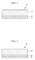
- Fig. 1 is a cross-sectional schematic view of a resin-based composite produced using the production method of a first embodiment.
- the resin-based composite 10 has a structure in which a first resin sheet 11, a conductive layer 12 that acts as a lightning-resistant layer, and a second resin sheet 13 are laminated in sequence.
- a resin-based composite of a structure in which the conductive layer is sandwiched between the first and second resin sheets in this manner the outermost surface can be made smooth.
- the case where a resin-based composite of the structure shown in Fig. 1 is used for the main wing structure of an aircraft is aerodynamically advantageous compared with a structure in which the lightning-resistant layer is provided on the outermost surface of the main wing structure.
- the first resin sheet 11 is a sheet formed from a glass fiber reinforced plastic (GFRP) prepared by immobilizing glass fibers within an epoxy resin.
- the second resin sheet 13 is a sheet formed from a carbon fiber reinforced plastic (CFRP) prepared by immobilizing carbon fibers within an epoxy resin.
- the conductive layer 12 is a conductive sheet formed from a resin containing a metal powder.
- the resin that constitutes the conductive sheet is, for example, a phenolic resin, epoxy resin, acrylic resin or urethane resin or the like. If a copper powder or silver powder is used as the metal powder, then good conductivity can be achieved.
- the conductive sheet can be obtained, for example, by using a sprayer or applicator to apply a predetermined thickness of the resin containing the metal powder to a molding sheet, performing heating and drying in an open atmosphere to remove the solvent within the resin and harden the resin, and then detaching the resin from the molding sheet.
- the molding sheet is a sheet in which, for example, the resin application surface has been coated with ethylene tetrafluoride, then the dried conductive sheet can be easily detached.
- the drying temperature is set to a temperature at which the resin being used undergoes hardening. For example, in the case of a phenolic resin, drying is performed within a temperature range from 130°C to 180°C. In the case of an epoxy resin, drying is performed within a temperature range from 60°C to 150°C.
- the resin-based composite 10 is produced using the steps described below.
- a conductive sheet that acts as the conductive layer 12 is positioned on a GFRP prepreg that functions as the first resin sheet 11.
- the edges of adjacent conductive sheets are overlapped, for example across a width of approximately 5 mm.
- the metal powder within the resin tends to sink to the molding sheet-side of the sheet, whereas the outer surface of the applied resin oxidizes during drying, and therefore the resistance value at the outer surface is greater than the resistance value at the molding sheet-side surface.
- increases in the resistance value at the contact surfaces can be prevented.
- a CFRP prepreg that functions as the second resin sheet 13 is positioned on the conductive sheet.
- the laminate prepared by laminating the GFRP prepreg, the conductive sheet and the CFRP prepreg is placed inside a vacuum bag.
- the laminate is then heated within a temperature range from 175°C to 185°C while the inside of the vacuum bag is evacuated, thereby bonding the prepregs and the conductive sheet to form the resin-based composite 10.
- a conductive sheet (a resin containing a metal powder that has been molded into sheet form in advance) as in the present embodiment, corrosion of the resin sheet by solvents and the generation of a water component during thermal bonding can be prevented.
- the conductive sheet which contains a resin as a main component, exhibits excellent handling properties such as superior flexibility and resistance to tearing compared with conventional copper foils. As a result, the workability during bonding can be improved significantly, and the conductive sheet can be bonded to the resin sheet across a large surface area, which is beneficial.
- the conductive sheet that contains a metal powder-containing resin as the main component is used as a lightning-resistant layer, the difference in the coefficients of thermal expansion for the lightning-resistant layer and the first and second resin sheets is small. As a result, the adhesion between the lightning-resistant layer and the first and second resin sheets is good.
- the type of burring of the lightning-resistant layer at the processed surface that is observed in conventional resin-based composites that use a copper foil as the lightning-resistant layer does not occur.
- the conductive layer is formed by applying a resin containing a metal powder to the first resin sheet.
- the resin and the metal powder employ the same materials as the first embodiment.
- the resin-based composite 10 is produced using the steps described below.
- the resin containing the metal powder is applied to a GFRP prepreg that functions as the first resin sheet 11.
- the application method may employ spray coating, or a resin paste may be applied using a coater.
- heating and drying is performed in an open atmosphere to remove the solvent within the resin and harden the resin, thus forming the conductive layer 12.
- the drying temperature is set to a temperature at which the resin being used undergoes hardening.
- a CFRP prepreg that functions as the second resin sheet 13 is positioned on the conductive layer 12.
- the laminate prepared by laminating the GFRP prepreg, the conductive layer and the CFRP prepreg is placed inside a vacuum bag.
- the laminate is then heated within a temperature range from 175°C to 185°C while the inside of the vacuum bag is evacuated, thereby bonding the prepregs and the conductive layer to form the resin-based composite 10.
- the metal powder-containing resin is applied directly to the FRP prepreg, if the amount of solvent contained within the resin is large, then the epoxy resin that constitutes the FRP prepreg may be corroded by the solvent. If the amount of solvent contained within the resin is small, then corrosion of the prepreg by the solvent can be prevented even when the metal powder-containing resin is applied directly to the FRP prepreg.
- the metal powder-containing resin is not dried following application, and a separate FRP prepreg is laminated and the resulting laminate then baked, then in the case of a phenolic resin for example, water is sometimes generated from the resin that represents the main component of the metal powder-containing resin- Consequently, the adhesion between the layer formed from the metal powder-containing resin and the resin sheet deteriorates, and the external appearance is also impaired, both of which are undesirable. Accordingly, it is preferable that following application of the metal powder-containing resin, drying is performed before the second resin sheet is laminated.
- Fig. 2 is a cross-sectional schematic view of a resin-based composite produced using the production method of a third embodiment.
- the resin-based composite 20 has a structure in which a conductive layer 22 that acts as a lightning-resistant layer is formed on one surface of a first resin sheet 21, and a second resin sheet 23 is formed on the other surface.
- the first resin sheet 21, the second resin sheet 22, and the conductive layer 23 are, respectively, a sheet formed from a glass fiber reinforced plastic (GFRP), a sheet formed from a carbon fiber reinforced plastic (CFRP), and a conductive sheet.
- GFRP glass fiber reinforced plastic
- CFRP carbon fiber reinforced plastic
- the resin-based composite 20 of the present embodiment is produced using the steps described below.
- a GFRP prepreg that functions as the first resin sheet 21 is positioned on a conductive sheet that acts as the conductive layer 22.
- the edges of adjacent conductive sheets are overlapped, for example across a width of approximately 5 mm.
- a CFRP prepreg that functions as the second resin sheet 23 is positioned on the GFRP prepreg to prepare a laminate.
- the laminate may also be formed by sequentially laminating the GFRP prepreg and the conductive sheet on the CFRP prepreg.
- the above-mentioned laminate is placed inside a vacuum bag.
- the laminate is then heated within a temperature range from 175°C to 185°C while the inside of the vacuum bag is evacuated, thereby bonding the prepregs and the conductive sheet to form the resin-based composite 20.
- the conductive layer is formed by applying a resin containing a metal powder to the first resin sheet to produce a resin-based composite of the structure illustrated in Fig. 2 .
- the resin-based composite 20 is produced using the steps described below.
- the resin containing the metal powder is applied to a GFRP prepreg that functions as the first resin sheet 21.
- heating and drying is performed in an open atmosphere to remove the solvent within the resin and harden the resin, thus forming the conductive layer 22.
- a CFRP prepreg that functions as the second resin sheet 23 is positioned on the surface of the first resin sheet 21 on the opposite side to the surface on which the conductive layer 22 is formed.
- the laminate prepared by laminating the conductive layer, the GFRP prepreg, and the CFRP prepreg is placed inside a vacuum bag. The laminate is then heated within a temperature range from 175°C to 185°C while the inside of the vacuum bag is evacuated, thereby bonding the prepregs and the conductive layer to form the resin-based composite 20.
- a resin-based composite was prepared in which the first resin sheet was a GFRP and the second resin sheet was a CFRP, but the present invention is not limited to such configurations.
- the present invention can also be applied to resin-based composites in which the first resin sheet is a CFRP and the second resin sheet is a GFRP.
- a copper paint (phenolic resin) was applied by spraying to an aluminum molding sheet, the surface of which had been coated with ethylene tetrafluoride.
- the copper paint-coated aluminum sheet was heated under conditions of 150°C for 30 minutes. Following cooling by standing, the film of copper paint was detached from the aluminum sheet to obtain a copper-containing conductive sheet.
- the thickness of the copper-containing conductive sheet was within a range from 70 ⁇ m to 85 ⁇ m.
- An applicator was used to apply a silver paste (urethane resin) to an aluminum molding sheet, the surface of which had been coated with ethylene tetrafluoride.
- the silver paste-coated aluminum sheet was heated under conditions of 80°C for 20 minutes. Following cooling by standing, the film of the silver paste was detached from the aluminum sheet to obtain a silver-containing conductive sheet.
- the thickness of the silver-containing conductive sheet was within a range from 100 ⁇ m to 150 ⁇ m.
- a laminate was prepared by sequentially positioning, on a GFRP prepreg (manufactured by Toray Industries, Inc., ultra thin type), a conductive sheet prepared by one of the methods described above or a copper foil (electrolytic copper foil) as a lightning-resistant layer, and a CFRP prepreg (manufactured by Toray Industries, Inc., a high-strength elastic unidirectional material).
- a GFRP prepreg manufactured by Toray Industries, Inc., ultra thin type
- a conductive sheet prepared by one of the methods described above or a copper foil (electrolytic copper foil) as a lightning-resistant layer
- a CFRP prepreg manufactured by Toray Industries, Inc., a high-strength elastic unidirectional material.
- the molding sheet-side surfaces of two conductive sheets were overlapped across a width of 5 mm.
- a laminate was prepared by sequentially laminating a GFRP prepreg and a CFRP prepreg on the
- the laminates were each placed in a vacuum bag, and thermal bonding was performed while the bag was evacuated to obtain a resin-based composite.
- the bonding conditions included: vacuum degree: 3.4 ⁇ 10 3 Pa, pressure: 5.9 ⁇ 10 5 Pa, heating temperature: 180°C, and heating time: 2 hours.
- each resin-based composite of the examples and comparative examples was inspected using a digital macroscope and a metallurgical microscope.
- the adhesion between the conductive sheet and the GFRP, and the adhesion between the conductive sheet and the CFRP were good.
- the adhesion between the conductive sheet and the CFRP was good.
- the adhesion between the conductive sheet and the GFRP was good.
- the resin-based composites of example 1 to example 6 no detachment occurred at the GFRP/conductive sheet interface or the CFRP/conductive sheet interface.
- the resin-based composites of comparative example 1 and comparative example 2 detachment occurred at the CFRP/copper foil interface.
- each of the resin-based composites of the examples and comparative examples was cut using a diamond cutter, and the cross-section was inspected using a digital microscope. In all of the resin-based composites of the examples, no burrs were generated. In the resin-based composites of the comparative examples, it was confirmed that burrs had been generated from the copper foil.
- the surface resistance at the outer surface and the molding sheet-side surface of the conductive sheets prepared using the above-mentioned methods, and the surface resistance (at the upper and lower surfaces) of the above copper foil were measured.
- the distance between the terminals was set to 100 mm.
- the GFRP was removed to expose the conductive sheet or the copper foil around two points that resulted in a distance between the terminals of 100 mm.
- the GFRP was removed around points positioned 50 mm to either side of the center of the overlapping portion between the two conductive sheets or copper foils.
- the conductive sheet surface was polished to remove the oxide film around two points that resulted in a distance between the terminals of 100 mm.
- the surface resistance (distance between terminals: 100 mm) of the conductive sheet or copper foil of each resin-based composite of the examples and comparative examples was measured.
- the conductive sheet, copper foil, and surface resistance for each of the examples and comparative examples are shown in Table 2.
- the outer surface side of the copper-containing conductive sheet oxidizes during drying, and therefore the surface resistance was larger than that of the molding sheet side.
- the surface resistance of the copper-containing conductive sheet was larger than the surface resistance of the copper foil, the value was satisfactory for use as a lightning-resistant layer of an aircraft main wing structure.
- the silver-containing conductive sheet had substantially the same resistance value at the outer surface side and the molding sheet side. When heating under conditions of 150°C was performed following preparation of the silver-containing conductive sheet, both of the resistance values became 8 m ⁇ .
- the surface resistance values of the examples were larger than the surface resistance values of the examples, but were satisfactory for use as a lightning-resistant layer of an aircraft main wing structure.
Applications Claiming Priority (2)
| Application Number | Priority Date | Filing Date | Title |
|---|---|---|---|
| JP2009039686A JP2010194749A (ja) | 2009-02-23 | 2009-02-23 | 樹脂基複合材の製造方法 |
| PCT/JP2010/051830 WO2010095536A1 (fr) | 2009-02-23 | 2010-02-08 | Procédé pour produire un composite à base de résine |
Publications (2)
| Publication Number | Publication Date |
|---|---|
| EP2399739A1 true EP2399739A1 (fr) | 2011-12-28 |
| EP2399739A4 EP2399739A4 (fr) | 2013-07-03 |
Family
ID=42633819
Family Applications (1)
| Application Number | Title | Priority Date | Filing Date |
|---|---|---|---|
| EP10743663.6A Withdrawn EP2399739A4 (fr) | 2009-02-23 | 2010-02-08 | Procédé pour produire un composite à base de résine |
Country Status (7)
| Country | Link |
|---|---|
| US (1) | US20110297315A1 (fr) |
| EP (1) | EP2399739A4 (fr) |
| JP (1) | JP2010194749A (fr) |
| CN (1) | CN102395465A (fr) |
| BR (1) | BRPI1007953A2 (fr) |
| CA (1) | CA2752575A1 (fr) |
| WO (1) | WO2010095536A1 (fr) |
Cited By (6)
| Publication number | Priority date | Publication date | Assignee | Title |
|---|---|---|---|---|
| WO2013028830A3 (fr) * | 2011-08-25 | 2013-06-27 | Lord Corporation | Système de protection parafoudre |
| WO2013103436A3 (fr) * | 2012-01-04 | 2013-08-29 | The Boeing Company | Système de dissipation de charges électriques pour avion |
| EP3000736A1 (fr) * | 2014-09-26 | 2016-03-30 | The Boeing Company | Procédé pour l'atténuation de l'incandescence des bords |
| US9484123B2 (en) | 2011-09-16 | 2016-11-01 | Prc-Desoto International, Inc. | Conductive sealant compositions |
| US9802714B2 (en) | 2010-12-03 | 2017-10-31 | The Boeing Company | Electric charge dissipation system for aircraft |
| US9840338B2 (en) | 2010-12-03 | 2017-12-12 | The Boeing Company | Electric charge dissipation system for aircraft |
Families Citing this family (10)
| Publication number | Priority date | Publication date | Assignee | Title |
|---|---|---|---|---|
| EP2675610A1 (fr) * | 2010-12-31 | 2013-12-25 | Cytec Technology Corp. | Procédé de fabrication d'une structure composite ayant une surface conductrice |
| JP5725868B2 (ja) | 2011-01-05 | 2015-05-27 | 三菱重工業株式会社 | 端部加工装置 |
| JP5773679B2 (ja) * | 2011-02-16 | 2015-09-02 | 三菱重工業株式会社 | 炭素繊維強化プラスチック構造体及びその製造方法 |
| RU2581104C1 (ru) | 2012-03-26 | 2016-04-10 | Мицубиси Хеви Индастрис, Лтд. | Топливный бак, основное крыло, фюзеляж летательного аппарата, летательный аппарат и подвижное тело |
| RU2605716C2 (ru) * | 2012-10-09 | 2016-12-27 | Мицубиси Хеви Индастрис, Лтд. | Конструкционный материал для изготовления элементов конструкции, топливного бака, основного крыла и летательного аппарата |
| JP6113544B2 (ja) * | 2013-03-26 | 2017-04-12 | 三菱重工業株式会社 | 燃料タンク、主翼、航空機胴体、航空機及び移動体 |
| JP6071686B2 (ja) | 2013-03-26 | 2017-02-01 | 三菱重工業株式会社 | 燃料タンク、主翼、航空機胴体、航空機及び移動体 |
| CN104562024B (zh) * | 2013-10-24 | 2017-08-25 | 富泰华精密电子(郑州)有限公司 | 金属与树脂的复合体及其制造方法 |
| JP6580359B2 (ja) | 2015-03-31 | 2019-09-25 | 三菱重工業株式会社 | 構造体製造方法および構造体 |
| EP3299297B1 (fr) | 2016-09-27 | 2018-12-12 | AIRBUS HELICOPTERS DEUTSCHLAND GmbH | Aéronef à voilure tournante avec un agencement structurel comprenant une connexion électriquement conductrice |
Citations (2)
| Publication number | Priority date | Publication date | Assignee | Title |
|---|---|---|---|---|
| WO2008048705A2 (fr) * | 2006-03-10 | 2008-04-24 | Goodrich Corporation | Protection contre un foudroiement de faible densité à utiliser dans des aéronefs |
| US20080295955A1 (en) * | 2006-11-06 | 2008-12-04 | Hexcel Composites, Ltd. | Composite materials |
Family Cites Families (5)
| Publication number | Priority date | Publication date | Assignee | Title |
|---|---|---|---|---|
| JPS6219435A (ja) * | 1985-07-18 | 1987-01-28 | Yuka Meramin Kk | 電磁波遮蔽樹脂積層板の製造方法 |
| US4746389A (en) * | 1987-08-04 | 1988-05-24 | United Technologies Corporation | Method for producing a clean, highly conductive surface for mating composite articles |
| EP0435044A3 (en) * | 1989-12-23 | 1992-05-13 | Bayer Ag | Half-product with electrically conductive plastic layers |
| WO2006042251A2 (fr) * | 2004-10-08 | 2006-04-20 | Bell Helicopter Textron Inc. | Appareil et procede pour traitement par ultrasons de stratifies |
| CN102317383B (zh) * | 2009-02-16 | 2014-07-23 | 塞特克技术公司 | 用于热固性复合材料的雷击及电磁干扰屏蔽的共固化导电表面膜 |
-
2009
- 2009-02-23 JP JP2009039686A patent/JP2010194749A/ja not_active Withdrawn
-
2010
- 2010-02-08 BR BRPI1007953A patent/BRPI1007953A2/pt not_active IP Right Cessation
- 2010-02-08 EP EP10743663.6A patent/EP2399739A4/fr not_active Withdrawn
- 2010-02-08 CN CN2010800085495A patent/CN102395465A/zh active Pending
- 2010-02-08 WO PCT/JP2010/051830 patent/WO2010095536A1/fr active Application Filing
- 2010-02-08 CA CA2752575A patent/CA2752575A1/fr not_active Abandoned
- 2010-02-08 US US13/201,509 patent/US20110297315A1/en not_active Abandoned
Patent Citations (2)
| Publication number | Priority date | Publication date | Assignee | Title |
|---|---|---|---|---|
| WO2008048705A2 (fr) * | 2006-03-10 | 2008-04-24 | Goodrich Corporation | Protection contre un foudroiement de faible densité à utiliser dans des aéronefs |
| US20080295955A1 (en) * | 2006-11-06 | 2008-12-04 | Hexcel Composites, Ltd. | Composite materials |
Non-Patent Citations (1)
| Title |
|---|
| See also references of WO2010095536A1 * |
Cited By (8)
| Publication number | Priority date | Publication date | Assignee | Title |
|---|---|---|---|---|
| US9802714B2 (en) | 2010-12-03 | 2017-10-31 | The Boeing Company | Electric charge dissipation system for aircraft |
| US9840338B2 (en) | 2010-12-03 | 2017-12-12 | The Boeing Company | Electric charge dissipation system for aircraft |
| US10513347B2 (en) | 2010-12-03 | 2019-12-24 | The Boeing Company | Electric charge dissipation system for aircraft |
| WO2013028830A3 (fr) * | 2011-08-25 | 2013-06-27 | Lord Corporation | Système de protection parafoudre |
| US9007739B2 (en) | 2011-08-25 | 2015-04-14 | Lord Corporation | Lightning strike protection system |
| US9484123B2 (en) | 2011-09-16 | 2016-11-01 | Prc-Desoto International, Inc. | Conductive sealant compositions |
| WO2013103436A3 (fr) * | 2012-01-04 | 2013-08-29 | The Boeing Company | Système de dissipation de charges électriques pour avion |
| EP3000736A1 (fr) * | 2014-09-26 | 2016-03-30 | The Boeing Company | Procédé pour l'atténuation de l'incandescence des bords |
Also Published As
| Publication number | Publication date |
|---|---|
| BRPI1007953A2 (pt) | 2016-02-23 |
| US20110297315A1 (en) | 2011-12-08 |
| CN102395465A (zh) | 2012-03-28 |
| CA2752575A1 (fr) | 2010-08-26 |
| EP2399739A4 (fr) | 2013-07-03 |
| WO2010095536A1 (fr) | 2010-08-26 |
| JP2010194749A (ja) | 2010-09-09 |
Similar Documents
| Publication | Publication Date | Title |
|---|---|---|
| EP2399739A1 (fr) | Procédé pour produire un composite à base de résine | |
| JP6478722B2 (ja) | 一体型落雷防護材料の作成システムおよび方法 | |
| US20130271891A1 (en) | Metallic Mesh and Lightning Strike Protection System | |
| CN110242358B (zh) | 复合材料叶片及其制造方法、前缘金属罩形成单元 | |
| JP7446735B2 (ja) | 一体型表面保護システム、複合材構造、及び、その保護方法 | |
| CN203510839U (zh) | 一种用于绝缘板或单面板的金属基离型膜 | |
| JP2006219078A (ja) | 航空機用複合体及び航空機の複合体構造部の製造方法 | |
| CN101472687B (zh) | 耐腐蚀蜂窝体 | |
| CN104340378B (zh) | 一种复合材料主桨叶铰链力矩超差的修理方法 | |
| US6126061A (en) | Element made of composite material including electrical continuity through the element | |
| CN115219415A (zh) | 一种测试胶粘剂粘接界面强度的双搭接试样及测试方法 | |
| WO2019172020A1 (fr) | Élément de couvercle de bord d'attaque, unité d'élément de couvercle de bord d'attaque, pale en composite, procédé de fabrication d'élément de couvercle de bord d'attaque, et procédé de fabrication d'une pale en composite | |
| US20210039341A1 (en) | Repair patch, method for molding repair patch, and method for repairing composite material | |
| US11156104B2 (en) | Systems and methods for bonding of dissimilar substrates | |
| JP2003326622A (ja) | 高熱伝導ハニカムサンドイッチパネルおよびこれを備えた人工衛星用機器搭載パネル | |
| CN111086224A (zh) | 热塑性复合材料电阻焊接用焊料、其制备方法及其应用 | |
| JPH04316845A (ja) | 複合材翼型成形方法 | |
| JP6110406B2 (ja) | 成形用治具の製造方法 | |
| JP4304855B2 (ja) | 複合金属テープの製造方法および製造装置 | |
| JP2014022583A (ja) | 圧電素子デバイスの製造方法 | |
| US20240035448A1 (en) | A conductive connection | |
| CN111048600A (zh) | 多功能复合面板和用于多功能复合面板的方法 | |
| CN117566091A (zh) | 一种复合材料与金属网共固化的直升机整流罩及制备方法 | |
| JP2007136977A (ja) | 複合機能フィルムとその製造方法 | |
| CN116330701A (zh) | 三维打印碳纤维复合材料表面的碳纤维包覆方法 |
Legal Events
| Date | Code | Title | Description |
|---|---|---|---|
| PUAI | Public reference made under article 153(3) epc to a published international application that has entered the european phase |
Free format text: ORIGINAL CODE: 0009012 |
|
| 17P | Request for examination filed |
Effective date: 20110819 |
|
| AK | Designated contracting states |
Kind code of ref document: A1 Designated state(s): AT BE BG CH CY CZ DE DK EE ES FI FR GB GR HR HU IE IS IT LI LT LU LV MC MK MT NL NO PL PT RO SE SI SK SM TR |
|
| DAX | Request for extension of the european patent (deleted) | ||
| A4 | Supplementary search report drawn up and despatched |
Effective date: 20130605 |
|
| RIC1 | Information provided on ipc code assigned before grant |
Ipc: B32B 27/18 20060101AFI20130529BHEP Ipc: B32B 5/28 20060101ALI20130529BHEP |
|
| STAA | Information on the status of an ep patent application or granted ep patent |
Free format text: STATUS: THE APPLICATION IS DEEMED TO BE WITHDRAWN |
|
| 18D | Application deemed to be withdrawn |
Effective date: 20140103 |