EP2397739B2 - Coupling for corrugated tube - Google Patents
Coupling for corrugated tube Download PDFInfo
- Publication number
- EP2397739B2 EP2397739B2 EP11171164.4A EP11171164A EP2397739B2 EP 2397739 B2 EP2397739 B2 EP 2397739B2 EP 11171164 A EP11171164 A EP 11171164A EP 2397739 B2 EP2397739 B2 EP 2397739B2
- Authority
- EP
- European Patent Office
- Prior art keywords
- main body
- coupling according
- ring
- previous
- coupling
- Prior art date
- Legal status (The legal status is an assumption and is not a legal conclusion. Google has not performed a legal analysis and makes no representation as to the accuracy of the status listed.)
- Active
Links
Images
Classifications
-
- F—MECHANICAL ENGINEERING; LIGHTING; HEATING; WEAPONS; BLASTING
- F16—ENGINEERING ELEMENTS AND UNITS; GENERAL MEASURES FOR PRODUCING AND MAINTAINING EFFECTIVE FUNCTIONING OF MACHINES OR INSTALLATIONS; THERMAL INSULATION IN GENERAL
- F16L—PIPES; JOINTS OR FITTINGS FOR PIPES; SUPPORTS FOR PIPES, CABLES OR PROTECTIVE TUBING; MEANS FOR THERMAL INSULATION IN GENERAL
- F16L25/00—Constructive types of pipe joints not provided for in groups F16L13/00 - F16L23/00 ; Details of pipe joints not otherwise provided for, e.g. electrically conducting or insulating means
- F16L25/0036—Joints for corrugated pipes
-
- F—MECHANICAL ENGINEERING; LIGHTING; HEATING; WEAPONS; BLASTING
- F24—HEATING; RANGES; VENTILATING
- F24S—SOLAR HEAT COLLECTORS; SOLAR HEAT SYSTEMS
- F24S80/00—Details, accessories or component parts of solar heat collectors not provided for in groups F24S10/00-F24S70/00
- F24S80/30—Arrangements for connecting the fluid circuits of solar collectors with each other or with other components, e.g. pipe connections; Fluid distributing means, e.g. headers
-
- F—MECHANICAL ENGINEERING; LIGHTING; HEATING; WEAPONS; BLASTING
- F28—HEAT EXCHANGE IN GENERAL
- F28F—DETAILS OF HEAT-EXCHANGE AND HEAT-TRANSFER APPARATUS, OF GENERAL APPLICATION
- F28F9/00—Casings; Header boxes; Auxiliary supports for elements; Auxiliary members within casings
- F28F9/02—Header boxes; End plates
- F28F9/0246—Arrangements for connecting header boxes with flow lines
Definitions
- the present invention relates to a coupling for a corrugated tube, that is to say a coupling for connecting a corrugated tube to a utility device, such as a solar panel or tank.
- EP-1347227A2 and EP-2278204-A2 disclose a coupling comprising a main body with a support seat an assembly seat, a cut ring and a nut to be serewed onto the main body.
- the purpose of the present invention is to make a coupling for a corrugated tube which is particularly easy and efficient to install.
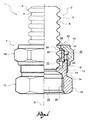
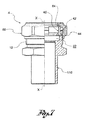
- FIG. 1 shows a partial view in longitudinal cross-section of a coupling according to the present innovation, in an initial assembly configuration
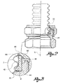
- figure 2 shows the coupling in figure 1 , in a final assembly configuration
- figure 3 shows an enlargement of the detail III in figure 2 ;
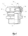
- FIG. 4 shows a view, partially in longitudinal cross-section, of a coupling according to the present invention according to a further embodiment, particularly suitable for screwing to the utility device;
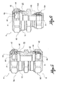
- FIG. 5 shows a view, partially in longitudinal cross-section, of a coupling according to the present invention according to a further embodiment, particularly suitable for connection to corrugated tubes at both ends;
- FIG. 6 shows a view, partially in longitudinal cross-section, of a coupling according to the present invention according to a further embodiment, particularly suitable for connection to a corrugated tube at one end and a copper pipe at the other end;
- FIG. 7 shows a view, partially in longitudinal cross-section, of a coupling according to the present invention, according to a further embodiment, particularly suitable for connection to a corrugated tube at one end and the insertion of the utility device at the other end.
- substantially sharp edged appears recurrently; such expression is understood to mean an edge deriving from machining structured so as not to include bevels or connections, as far as permitted by the technological limitations of such machining, by the tools utilised therein and materials utilised for the component.
- reference numeral 1 globally denotes an assembly comprising a corrugated tube 2 and a coupling 4 for the connection of the corrugated tube to a utility device, such as a solar panel or tank.
- the corrugated tube 2 has, along a longitudinal axis X, a sequence of corrugations which form an alternate succession of peaks 6 and valleys 8.
- the tube 2 terminates, at the end engaging with the coupling 4, in a terminal corrugation, having a terminal crest 6'.
- the corrugated tube is made of metal.
- the coupling 4 hollow on the inside for the transit of the fluid, comprises a main body 10, preferably made in a single piece, for example in brass.
- the main body 10 comprises a threaded outer portion 12, a relief groove 14 and a grip head 16, preferably of a polygonal shape, to permit the gripping of a tool, such as a spanner, for fitting the coupling 4 to the utility device.
- the main body 10 comprises an annular support seat 20, defined on the bottom by a crown-shaped support surface 20', contained on a plane, and an annular assembly seat 22, having a smaller diameter than that of the support seat.
- the support seat 20 is defined circumferentially by a cylindrical surface; in the same way the assembly seat 22 is defined circumferentially by a cylindrical surface.
- the passage from the support seat 20 to the assembly seat 22 is defined circumferentially by a substantially sharp edge (consisting of the inner diameter of the circular crown defining the support surface 20').
- the assembly seat 22 has a circumferentially continuous annular abutment wall 24 on the bottom having a radial extension such as to permit the abutment of the end of the tube and in particular of the terminal corrugation thereof.
- the main body 10 On the other side of the abutment wall 24, the main body 10 has an engagement recess 26 defined by an inner threaded portion 28, for screwing to the utility device.
- the coupling 4 further comprises a ring 40 preferably made in a single piece, having a longitudinal slit through its thickness and from one end of the other, which confers structural stability.
- Such structural flexibility permits a deformation of the ring which, in a non-deformed configuration, such as that shown in figure 1 , has a larger inner or outer diameter than in a deformed configuration, such as that shown in figure 2 .
- the ring 40 comprises a main annular wall 42, having a substantially constant inner and outer diameter, and an annular support foot 44.
- the support foot 44 is preferably cylindrical on the outside, ending with a substantially sharp edge and flush with the main wall 42; preferably, moreover, said foot 44 is internally at least partially tapered, converging towards the support wall 20 of the main body 10.
- the coupling 4 further comprises a nut 60, which can be screwed onto the inner portion 12 of the main body 10 and fitted internally with an active wall 62 to use for assembly to the ring 40.
- the active wall 62 has a tapered contact surface 64, divergent towards the main body 10.
- the active wall 62 comprises an annular shoulder 66 of a cylindrical shape in correspondence with the minimum diameter of the contact surface 64, having an inner diameter even smaller than the minimum diameter of the contact surface.
- the nut 60 is outwardly shaped in a polygonal manner, so as to be gripped by an assembly tool.
- the ring 40 In an initial assembly configuration of the tube 2 to the coupling 4 ( figure 1 ), the ring 40 is in the non-deformed configuration and rests against the support surface 20'; in particular the foot 44 of the ring 40 abuts against said support surface 20'.
- the nut 60 is partially screwed to the main body 10, so that the ring 40 and in particular the main wall 42 thereof, abuts against the active wall 62 of the nut 60, and in particular against the tapered contact surface 64.
- the tube 2 is inserted in the coupling 4 and the end of it abuts with the abutment wall 24 of the main body 10.
- the terminal corrugation of the tube which abuts with the abutment wall 24, is positioned between the foot 44 of the ring 40 and said abutment wall.
- the minimum inner diameter of the foot 44 of the ring 40 is less than the maximum diameter of the terminal crest 6', so that the tube 2 is snap inserted in the coupling.
- the at least partially tapered shape of the foot 44 of the ring 40 facilitates the insertion of the terminal crest 6' of the tube and its snap engagement.
- the snap insertion of the corrugated tube in the ring defines the position of the end of the tube in relation to the ring and consequently in relation to the coupling body during assembly, without further intervention by the operator performing assembly.
- the coupling passes from the initial configuration to the final assembly configuration ( figure 2 ).
- the active wall 62 of the nut 60 influences the ring 40 so as to compress it and reduce its radial dimension, so that the ring enters the assembly seat 22 and is pushed towards the abutment wall 24 of the main body 10.
- the substantially sharp edge between the support seat 20 and the assembly seat 22 does not form a guide for insertion of the ring 40, but causes its almost snap insertion.
- the foot 44 of the ring 40 interferes with the terminal corrugation of the tube and flattens it against the abutment wall 24 ( figure 3 ), securing the connection between the tube and the coupling.
- a portion of the ring 40, and in particular a portion of the main wall 42, projects axially from the assembly seat 22 and from the support seat 20, so as to continue to be in abutment with the active wall 62 of the nut.
- the foot 44 is pushed against the abutment wall 24, having a radial extension such that the foot is completely contained radially on the support surface of said abutment wall.
- the coupling according to the present invention has been shown to be particularly efficacious for the sealed connection of the tube and the coupling.
- the coupling according to the present invention has been shown to be particularly convenient for use by assembly technicians in that it permits the connection without excessive effort.
- the coupling provides an excellent seal between the corrugated tube and the body since the terminal corrugation, which when assembly is completed, remains flattened between the ring and the abutment wall, is substantially flat.
- the coupling can be reutilised in that as said the terminal corrugation, after assembly has been completed, is substantially flat and the ring, after dismantling, returns substantially to its original condition.
- the corrugated tube can then be extracted from the body and together with the ring inserted in a different body.
- the main body externally has on the outside, at the other longitudinal end, a threading for the threaded connection to the utility device.
- the main body comprises internally, at the other longitudinal end, a further support seat and a further assembly seat, for engagement with a further cut ring and a further screwable nut, for connection to a further corrugated tube.
- the main body has, on the inside, a guide chamfer 100 and the coupling further comprises:
- Such embodiment is particularly suitable for connection with a copper pipe.
- the main body comprises an insert 110, smooth on the inside and outside, for insertion in the utility device.
Description
- The present invention relates to a coupling for a corrugated tube, that is to say a coupling for connecting a corrugated tube to a utility device, such as a solar panel or tank.
- Numerous embodiments of couplings for corrugated tubes exist. Some of these are illustrated in the documents
DE 202006013841 ,DE 202009004737 ,DE 202010008064 ,EP 1431645 ,EP 1983244 ,EP 915282 EP 1479960 ,DE 202004005579 ,DE 102008003675 ,DE 102007042606 andEP 2133613 . - Particularly,
EP-1347227A2 andEP-2278204-A2 disclose a coupling comprising a main body with a support seat an assembly seat, a cut ring and a nut to be serewed onto the main body. - Despite such numerous embodiments, there is significant R&D activity in the sector, targeted at developing solutions to improve the performance of the known embodiments; this has been particularly true in recent years on account of the considerable importance acquired by the solar panel installation sector.
- In particular, the purpose of the present invention is to make a coupling for a corrugated tube which is particularly easy and efficient to install.
- Such purpose is achieved by a coupling for a corrugated tube according to claim 1.
- The characteristics and advantages of the coupling according to the present innovation will be evident from the description given below, made by way of a nonlimiting example, according to the appended drawings, wherein:
- -
figure 1 shows a partial view in longitudinal cross-section of a coupling according to the present innovation, in an initial assembly configuration; - -
figure 2 shows the coupling infigure 1 , in a final assembly configuration; and - -
figure 3 shows an enlargement of the detail III infigure 2 ; - -
figure 4 shows a view, partially in longitudinal cross-section, of a coupling according to the present invention according to a further embodiment, particularly suitable for screwing to the utility device; - -
figure 5 shows a view, partially in longitudinal cross-section, of a coupling according to the present invention according to a further embodiment, particularly suitable for connection to corrugated tubes at both ends; - -
figure 6 shows a view, partially in longitudinal cross-section, of a coupling according to the present invention according to a further embodiment, particularly suitable for connection to a corrugated tube at one end and a copper pipe at the other end; and - -
figure 7 shows a view, partially in longitudinal cross-section, of a coupling according to the present invention, according to a further embodiment, particularly suitable for connection to a corrugated tube at one end and the insertion of the utility device at the other end. - In the following description the term "substantially sharp edged" appears recurrently; such expression is understood to mean an edge deriving from machining structured so as not to include bevels or connections, as far as permitted by the technological limitations of such machining, by the tools utilised therein and materials utilised for the component.
- With reference to the appended drawings, reference numeral 1 globally denotes an assembly comprising a
corrugated tube 2 and acoupling 4 for the connection of the corrugated tube to a utility device, such as a solar panel or tank. - The
corrugated tube 2 has, along a longitudinal axis X, a sequence of corrugations which form an alternate succession ofpeaks 6 andvalleys 8. Thetube 2 terminates, at the end engaging with thecoupling 4, in a terminal corrugation, having a terminal crest 6'. - Preferably, the corrugated tube is made of metal.
- The
coupling 4, hollow on the inside for the transit of the fluid, comprises amain body 10, preferably made in a single piece, for example in brass. - From the engagement end with the tube to the opposite end, destined for engagement with the utility device, externally the
main body 10 comprises a threadedouter portion 12, arelief groove 14 and a grip head 16, preferably of a polygonal shape, to permit the gripping of a tool, such as a spanner, for fitting thecoupling 4 to the utility device. - Internally, from the engagement end with the tube to the end destined for engagement with the utility device, the
main body 10 comprises anannular support seat 20, defined on the bottom by a crown-shaped support surface 20', contained on a plane, and anannular assembly seat 22, having a smaller diameter than that of the support seat. - The
support seat 20 is defined circumferentially by a cylindrical surface; in the same way theassembly seat 22 is defined circumferentially by a cylindrical surface. - The passage from the
support seat 20 to theassembly seat 22 is defined circumferentially by a substantially sharp edge (consisting of the inner diameter of the circular crown defining the support surface 20'). - The
assembly seat 22 has a circumferentially continuousannular abutment wall 24 on the bottom having a radial extension such as to permit the abutment of the end of the tube and in particular of the terminal corrugation thereof. - On the other side of the
abutment wall 24, themain body 10 has anengagement recess 26 defined by an inner threadedportion 28, for screwing to the utility device. - The
coupling 4 further comprises aring 40 preferably made in a single piece, having a longitudinal slit through its thickness and from one end of the other, which confers structural stability. - Such structural flexibility permits a deformation of the ring which, in a non-deformed configuration, such as that shown in
figure 1 , has a larger inner or outer diameter than in a deformed configuration, such as that shown infigure 2 . - In particular, the
ring 40 comprises a mainannular wall 42, having a substantially constant inner and outer diameter, and anannular support foot 44. - The
support foot 44 is preferably cylindrical on the outside, ending with a substantially sharp edge and flush with themain wall 42; preferably, moreover, saidfoot 44 is internally at least partially tapered, converging towards thesupport wall 20 of themain body 10. - The
coupling 4 further comprises anut 60, which can be screwed onto theinner portion 12 of themain body 10 and fitted internally with anactive wall 62 to use for assembly to thering 40. - In particular, the
active wall 62 has atapered contact surface 64, divergent towards themain body 10. - In addition, preferably, the
active wall 62 comprises anannular shoulder 66 of a cylindrical shape in correspondence with the minimum diameter of thecontact surface 64, having an inner diameter even smaller than the minimum diameter of the contact surface. - Preferably, the
nut 60, is outwardly shaped in a polygonal manner, so as to be gripped by an assembly tool. - In an initial assembly configuration of the
tube 2 to the coupling 4 (figure 1 ), thering 40 is in the non-deformed configuration and rests against the support surface 20'; in particular thefoot 44 of thering 40 abuts against said support surface 20'. - The
nut 60 is partially screwed to themain body 10, so that thering 40 and in particular themain wall 42 thereof, abuts against theactive wall 62 of thenut 60, and in particular against thetapered contact surface 64. - The
tube 2 is inserted in thecoupling 4 and the end of it abuts with theabutment wall 24 of themain body 10. In particular, the terminal corrugation of the tube, which abuts with theabutment wall 24, is positioned between thefoot 44 of thering 40 and said abutment wall. - Preferably, the minimum inner diameter of the
foot 44 of thering 40 is less than the maximum diameter of the terminal crest 6', so that thetube 2 is snap inserted in the coupling. Advantageously, the at least partially tapered shape of thefoot 44 of thering 40 facilitates the insertion of the terminal crest 6' of the tube and its snap engagement. - Advantageously, in addition, the snap insertion of the corrugated tube in the ring defines the position of the end of the tube in relation to the ring and consequently in relation to the coupling body during assembly, without further intervention by the operator performing assembly.
- Moreover, such size of ring prevents the accidental escape of the coupling tube during handling before mechanical tightening.
- By screwing the
nut 60 to themain body 10, the coupling passes from the initial configuration to the final assembly configuration (figure 2 ). - During screwing, the
active wall 62 of thenut 60 influences thering 40 so as to compress it and reduce its radial dimension, so that the ring enters theassembly seat 22 and is pushed towards theabutment wall 24 of themain body 10. - The substantially sharp edge between the
support seat 20 and theassembly seat 22 does not form a guide for insertion of thering 40, but causes its almost snap insertion. - Furthermore, the
foot 44 of thering 40, interferes with the terminal corrugation of the tube and flattens it against the abutment wall 24 (figure 3 ), securing the connection between the tube and the coupling. - In the assembly configuration, a portion of the
ring 40, and in particular a portion of themain wall 42, projects axially from theassembly seat 22 and from thesupport seat 20, so as to continue to be in abutment with theactive wall 62 of the nut. - In said configuration moreover, the
foot 44 is pushed against theabutment wall 24, having a radial extension such that the foot is completely contained radially on the support surface of said abutment wall. - Innovatively, the coupling according to the present invention has been shown to be particularly efficacious for the sealed connection of the tube and the coupling.
- Moreover, the coupling according to the present invention has been shown to be particularly convenient for use by assembly technicians in that it permits the connection without excessive effort.
- Advantageously moreover the coupling provides an excellent seal between the corrugated tube and the body since the terminal corrugation, which when assembly is completed, remains flattened between the ring and the abutment wall, is substantially flat.
- According to a further advantageous aspect, the coupling can be reutilised in that as said the terminal corrugation, after assembly has been completed, is substantially flat and the ring, after dismantling, returns substantially to its original condition. The corrugated tube can then be extracted from the body and together with the ring inserted in a different body.
- It is clear that a person skilled in the art may make modifications to the coupling described above so as to satisfy contingent requirements.
- For example, according to one embodiment variation (
figure 4 ), the main body externally has on the outside, at the other longitudinal end, a threading for the threaded connection to the utility device. - According to a further embodiment variation (
figure 5 ), the main body comprises internally, at the other longitudinal end, a further support seat and a further assembly seat, for engagement with a further cut ring and a further screwable nut, for connection to a further corrugated tube. - According to a further embodiment variation (
figure 6 ), at the other end, the main body has, on the inside, a guide chamfer 100 and the coupling further comprises: - a
deformable ogive 102; and - a
secondary nut 104, which can be screwed to said further end, suitable for pressing the ogive against theguide chamfer 100 to deform it permanently. - Such embodiment is particularly suitable for connection with a copper pipe.
- According to yet a further embodiment variation (
figure 7 ), at the other end, the main body comprises an insert 110, smooth on the inside and outside, for insertion in the utility device. - Such variations are also contained within the sphere of protection as defined by the appended claims.
Claims (15)
- Coupling (4) for a corrugated tube (2) extending along a longitudinal axis (X), comprising:- a main body (10) comprising internally, at one longitudinal end:a) a support seat (20) defined circumferentially by a cylindrical surface and defined on the bottom by a crown-shaped support surface (20');b) an assembly seat (22), adjacent to the support seat (20) having a smaller inner diameter than that of the support seat, defined on the bottom by an abutment wall (24) having a radial extension, destined to abut with the end of the tube inserted in said main body;- a cut ring (40), suitable to be restricted in dimension from an initial non-deformed rest configuration, in which it abuts with the support surface (20') of the support seat (20) of the main body and a deformed assembly configuration in which it is at least partially housed in the assembly seat (22) of the main body- a nut (60) which can be screwed onto the main body (10), fitted internally with an at least partially tapered active wall (62) to narrow the ring during screwing of the nut to the main body,
wherein the ring (40) comprises a main body (42), defined by cylindrical surfaces inwardly and outwardly, in contact with the active wall (62) of the nut (60) and an annular foot (44) abutting with the crown-shaped support surface (20') of the main body (10) in the initial non-deformed configuration of the ring (40). - Coupling according to claim 1, wherein the foot (44) has internally, an at least partially tapered guide surface for the insertion of the tube.
- Coupling according to any of the previous claims, wherein, in said deformed assembly configuration, the foot (44) of the ring (40) is completely contained radially on the support surface of said abutment wall (24).
- Coupling according to any of the previous claims, wherein the main body is made in a single piece, for example in brass.
- Coupling according to any of the previous claims, wherein the ring has a slit through its thickness and from one end to the other, to give said structural flexibility.
- Coupling according to any of the previous claims, wherein the ring is made in a single piece, for example in brass.
- Coupling according to any of the previous claims, wherein the nut is made in a single piece, for example in brass.
- Coupling according to any of the previous claims, wherein the passage from the support seat (20) to the assembly seat (22) is defined circumferentially by a substantially sharp edge.
- Coupling according to any of the previous claims, wherein the support foot (44) ends with a substantially sharp edge.
- Coupling according to any of the previous claims, wherein the main body is fitted with an outer threaded portion (12) for screwing the nut (60) onto.
- Coupling according to any of the previous claims, wherein, on the side opposite the ring (40), the main body is fitted with an outer threaded portion (12) for screwing to the utility device.
- Coupling according to any of the previous claims, wherein, on the side opposite the ring (40), the main body is fitted with an inner threaded portion (28) for screwing to the utility device.
- Coupling according to any of the claims from 1 to 10, wherein the main body comprises internally, at the other longitudinal end, a further support seat and a further assembly seat, for engagement with a further cut ring and a further screwable nut, for connection to a further corrugated tube.
- Coupling according to any of the claims from 1 to 10, wherein, at the other end the main body has, on the inside, a guide chamfer (100), said coupling further comprising:- a deformable ogive (102); and- a secondary nut (104), which can be screwed to said further end, suitable for pressing the ogive against the guide chamfer (100) to deform it permanently;
for connection, for example, to a copper pipe. - Coupling according to any of the claims from 1 to 10, wherein at the other end, the main body comprises an insert (110), smooth on the inside and outside, for insertion in the utility device.
Priority Applications (1)
| Application Number | Priority Date | Filing Date | Title |
|---|---|---|---|
| PL11171164T PL2397739T5 (en) | 2011-02-10 | 2011-06-23 | Coupling for corrugated tube |
Applications Claiming Priority (1)
| Application Number | Priority Date | Filing Date | Title |
|---|---|---|---|
| IT000008U ITBS20110008U1 (en) | 2011-02-10 | 2011-02-10 | CONNECTOR FOR CORRUGATED TUBE |
Publications (3)
| Publication Number | Publication Date |
|---|---|
| EP2397739A1 EP2397739A1 (en) | 2011-12-21 |
| EP2397739B1 EP2397739B1 (en) | 2012-12-12 |
| EP2397739B2 true EP2397739B2 (en) | 2016-02-24 |
Family
ID=43976618
Family Applications (1)
| Application Number | Title | Priority Date | Filing Date |
|---|---|---|---|
| EP11171164.4A Active EP2397739B2 (en) | 2011-02-10 | 2011-06-23 | Coupling for corrugated tube |
Country Status (4)
| Country | Link |
|---|---|
| EP (1) | EP2397739B2 (en) |
| ES (1) | ES2400078T5 (en) |
| IT (1) | ITBS20110008U1 (en) |
| PL (1) | PL2397739T5 (en) |
Families Citing this family (4)
| Publication number | Priority date | Publication date | Assignee | Title |
|---|---|---|---|---|
| US11306850B2 (en) | 2017-10-24 | 2022-04-19 | Dong-A Flexible Metal Tubes Co., Ltd. | Connecting device for corrugated pipe and coupling method thereof |
| FR3074875B1 (en) | 2017-12-08 | 2020-04-17 | Dualsun | FLUIDIC CONNECTION DEVICE FOR HEAT EXCHANGERS OF AT LEAST TWO HYBRID SOLAR PANELS |
| WO2020236106A1 (en) | 2019-05-23 | 2020-11-26 | Haci Ayvaz Endüstri̇yel Mamüller Sanayi̇ Ve Ti̇caret Anoni̇m Şi̇rketi̇ | Hose connection apparatus |
| FR3102318B1 (en) | 2019-10-17 | 2022-12-30 | Dualsun | installation comprising connectors for the fluidic connection of a heat exchanger of at least one hybrid solar panel |
Citations (1)
| Publication number | Priority date | Publication date | Assignee | Title |
|---|---|---|---|---|
| EP2278204A2 (en) † | 2009-07-17 | 2011-01-26 | Gebrüder Beul GmbH & Co KG | Screw connection for corrugated pipe |
Family Cites Families (15)
| Publication number | Priority date | Publication date | Assignee | Title |
|---|---|---|---|---|
| US3834743A (en) * | 1972-11-20 | 1974-09-10 | Imp Eastman Corp | Tube coupling |
| DE19749251A1 (en) | 1997-11-07 | 1999-05-27 | Witzenmann Metallschlauchfab | Connection connection |
| FR2794214B1 (en) * | 1999-05-31 | 2001-08-10 | Capri Codec Sa | CONNECTION FOR BRAIDED SHEATH |
| ES2280639T3 (en) | 2002-03-22 | 2007-09-16 | Witzenmann Gmbh | PUMP DEVICE FOR A ROLLED METAL FLEXIBLE TUBE. |
| DE20219884U1 (en) | 2002-12-21 | 2004-04-22 | Kulm Holding Ag | Tube Fitting |
| DE20307753U1 (en) | 2003-05-17 | 2003-07-10 | Witzenmann Gmbh | Plug connection between a corrugated metal hose and a connector |
| DE202004005579U1 (en) | 2004-04-08 | 2004-06-09 | Witzenmann Gmbh | Solar collector has pipe or hose line elements allowing connections for serial configuration of several solar collectors |
| EP1605196A1 (en) | 2004-06-08 | 2005-12-14 | Hassan Obahi | Self-sealing pre-assembled endfitting/coupling for corrugated tubing |
| DE202006013841U1 (en) | 2006-09-09 | 2006-11-09 | Gebrüder Beul GmbH & Co. KG | Connector for corrugated pipes has base with sloping upper surface, union nut being screwed on to connector which presses press-fitting with corresponding lower surface down so that lowest corrugation of pipe is flattened and held in place |
| DE202007001392U1 (en) | 2007-01-31 | 2008-06-05 | Witzenmann Gmbh | Connector for a metal pipe or a metal hose and arrangement with such a connector |
| EP1983244B1 (en) | 2007-04-17 | 2012-10-03 | SERTO Holding AG | Coupling arrangement for corrugated metal tube |
| DE102007042606A1 (en) | 2007-09-07 | 2009-03-12 | Witzenmann Gmbh | Annular or threaded corrugated metal tube e.g. pressure-resistant fluid line, manufacturing method for air conditioner of motor vehicle, involves pulling off taper drift outwardly by channel, so that connection section is radially expanded |
| DE102008027843A1 (en) | 2008-06-11 | 2010-01-07 | Witzenmann Gmbh | Connecting element and connection connection, in particular for connecting solar collectors |
| DE202009004737U1 (en) | 2009-04-24 | 2010-09-16 | Gebrüder Beul GmbH & Co KG | pipe connectors |
| DE202010008064U1 (en) | 2010-07-13 | 2010-09-02 | Gebrüder Beul GmbH & Co KG | Spiral corrugated pipe attachment connector |
-
2011
- 2011-02-10 IT IT000008U patent/ITBS20110008U1/en unknown
- 2011-06-23 EP EP11171164.4A patent/EP2397739B2/en active Active
- 2011-06-23 ES ES11171164T patent/ES2400078T5/en active Active
- 2011-06-23 PL PL11171164T patent/PL2397739T5/en unknown
Patent Citations (1)
| Publication number | Priority date | Publication date | Assignee | Title |
|---|---|---|---|---|
| EP2278204A2 (en) † | 2009-07-17 | 2011-01-26 | Gebrüder Beul GmbH & Co KG | Screw connection for corrugated pipe |
Also Published As
| Publication number | Publication date |
|---|---|
| PL2397739T3 (en) | 2015-05-31 |
| ES2400078T5 (en) | 2016-05-24 |
| EP2397739B1 (en) | 2012-12-12 |
| PL2397739T5 (en) | 2017-03-31 |
| ITBS20110008U1 (en) | 2012-08-11 |
| EP2397739A1 (en) | 2011-12-21 |
| ES2400078T3 (en) | 2013-04-05 |
Similar Documents
| Publication | Publication Date | Title |
|---|---|---|
| US4437691A (en) | Connector for corrugated tubing | |
| EP2372214B1 (en) | Resin pipe joint | |
| EP2609356B1 (en) | Fitting | |
| EP2397739B2 (en) | Coupling for corrugated tube | |
| JPH07103222A (en) | Detent locking device | |
| US11614184B2 (en) | Method for making a threaded connection for pipes, such as oil and gas pipes | |
| EP2322834A1 (en) | Tube joint consisting of resin | |
| US20110318099A1 (en) | Anchor device for anchoring an element such as a fluid coupling in an opening in a wall | |
| US20070284878A1 (en) | Sealing fitting for stainless steel tubing | |
| US20160223112A1 (en) | Hose line and method for producing a hose line | |
| CN109073120B (en) | Catheter fitting with travel impedance feature | |
| EP1041330A1 (en) | Pipe joint made of resin | |
| US6840139B2 (en) | Tapered installation tool | |
| CN210106775U (en) | Stainless steel corrugated pipe with threaded connector for gas appliance | |
| KR200461502Y1 (en) | Stopper for pipe | |
| JP6059777B1 (en) | Pipe fitting | |
| CN213712055U (en) | Lead screw rust prevention device | |
| JP3014875U (en) | Cable grounding device for explosion-proof cable gland for steel pipe insulation cable | |
| JPS6246067Y2 (en) | ||
| JP4568630B2 (en) | Pipe fitting | |
| EP2737585A2 (en) | Metal conduit assemblies | |
| JPH08233165A (en) | Pipe joint | |
| WO2018102887A1 (en) | Pipe fitting | |
| JPH0480276B2 (en) | ||
| JPH06257693A (en) | Flexible tube connecting device |
Legal Events
| Date | Code | Title | Description |
|---|---|---|---|
| 17P | Request for examination filed |
Effective date: 20111110 |
|
| AK | Designated contracting states |
Kind code of ref document: A1 Designated state(s): AL AT BE BG CH CY CZ DE DK EE ES FI FR GB GR HR HU IE IS IT LI LT LU LV MC MK MT NL NO PL PT RO RS SE SI SK SM TR |
|
| AX | Request for extension of the european patent |
Extension state: BA ME |
|
| PUAI | Public reference made under article 153(3) epc to a published international application that has entered the european phase |
Free format text: ORIGINAL CODE: 0009012 |
|
| TPAC | Observations filed by third parties |
Free format text: ORIGINAL CODE: EPIDOSNTIPA |
|
| GRAP | Despatch of communication of intention to grant a patent |
Free format text: ORIGINAL CODE: EPIDOSNIGR1 |
|
| GRAS | Grant fee paid |
Free format text: ORIGINAL CODE: EPIDOSNIGR3 |
|
| GRAA | (expected) grant |
Free format text: ORIGINAL CODE: 0009210 |
|
| AK | Designated contracting states |
Kind code of ref document: B1 Designated state(s): AL AT BE BG CH CY CZ DE DK EE ES FI FR GB GR HR HU IE IS IT LI LT LU LV MC MK MT NL NO PL PT RO RS SE SI SK SM TR |
|
| REG | Reference to a national code |
Ref country code: GB Ref legal event code: FG4D |
|
| REG | Reference to a national code |
Ref country code: CH Ref legal event code: EP |
|
| REG | Reference to a national code |
Ref country code: AT Ref legal event code: REF Ref document number: 588500 Country of ref document: AT Kind code of ref document: T Effective date: 20121215 |
|
| REG | Reference to a national code |
Ref country code: IE Ref legal event code: FG4D |
|
| REG | Reference to a national code |
Ref country code: DE Ref legal event code: R096 Ref document number: 602011000579 Country of ref document: DE Effective date: 20130207 |
|
| REG | Reference to a national code |
Ref country code: ES Ref legal event code: FG2A Ref document number: 2400078 Country of ref document: ES Kind code of ref document: T3 Effective date: 20130405 |
|
| PLBI | Opposition filed |
Free format text: ORIGINAL CODE: 0009260 |
|
| PG25 | Lapsed in a contracting state [announced via postgrant information from national office to epo] |
Ref country code: HR Free format text: LAPSE BECAUSE OF FAILURE TO SUBMIT A TRANSLATION OF THE DESCRIPTION OR TO PAY THE FEE WITHIN THE PRESCRIBED TIME-LIMIT Effective date: 20121212 Ref country code: NO Free format text: LAPSE BECAUSE OF FAILURE TO SUBMIT A TRANSLATION OF THE DESCRIPTION OR TO PAY THE FEE WITHIN THE PRESCRIBED TIME-LIMIT Effective date: 20130312 Ref country code: SE Free format text: LAPSE BECAUSE OF FAILURE TO SUBMIT A TRANSLATION OF THE DESCRIPTION OR TO PAY THE FEE WITHIN THE PRESCRIBED TIME-LIMIT Effective date: 20121212 Ref country code: FI Free format text: LAPSE BECAUSE OF FAILURE TO SUBMIT A TRANSLATION OF THE DESCRIPTION OR TO PAY THE FEE WITHIN THE PRESCRIBED TIME-LIMIT Effective date: 20121212 Ref country code: LT Free format text: LAPSE BECAUSE OF FAILURE TO SUBMIT A TRANSLATION OF THE DESCRIPTION OR TO PAY THE FEE WITHIN THE PRESCRIBED TIME-LIMIT Effective date: 20121212 |
|
| REG | Reference to a national code |
Ref country code: NL Ref legal event code: VDEP Effective date: 20121212 Ref country code: GR Ref legal event code: EP Ref document number: 20130400334 Country of ref document: GR Effective date: 20130327 |
|
| REG | Reference to a national code |
Ref country code: LT Ref legal event code: MG4D |
|
| 26 | Opposition filed |
Opponent name: WITZENMANN GMBH METALLSCHLAUCH-FABRIK PFORZHEIM Effective date: 20130418 |
|
| PG25 | Lapsed in a contracting state [announced via postgrant information from national office to epo] |
Ref country code: LV Free format text: LAPSE BECAUSE OF FAILURE TO SUBMIT A TRANSLATION OF THE DESCRIPTION OR TO PAY THE FEE WITHIN THE PRESCRIBED TIME-LIMIT Effective date: 20121212 Ref country code: SI Free format text: LAPSE BECAUSE OF FAILURE TO SUBMIT A TRANSLATION OF THE DESCRIPTION OR TO PAY THE FEE WITHIN THE PRESCRIBED TIME-LIMIT Effective date: 20121212 |
|
| REG | Reference to a national code |
Ref country code: PL Ref legal event code: T3 |
|
| REG | Reference to a national code |
Ref country code: DE Ref legal event code: R026 Ref document number: 602011000579 Country of ref document: DE Effective date: 20130418 |
|
| PG25 | Lapsed in a contracting state [announced via postgrant information from national office to epo] |
Ref country code: EE Free format text: LAPSE BECAUSE OF FAILURE TO SUBMIT A TRANSLATION OF THE DESCRIPTION OR TO PAY THE FEE WITHIN THE PRESCRIBED TIME-LIMIT Effective date: 20121212 Ref country code: BE Free format text: LAPSE BECAUSE OF FAILURE TO SUBMIT A TRANSLATION OF THE DESCRIPTION OR TO PAY THE FEE WITHIN THE PRESCRIBED TIME-LIMIT Effective date: 20121212 Ref country code: IS Free format text: LAPSE BECAUSE OF FAILURE TO SUBMIT A TRANSLATION OF THE DESCRIPTION OR TO PAY THE FEE WITHIN THE PRESCRIBED TIME-LIMIT Effective date: 20130412 Ref country code: RS Free format text: LAPSE BECAUSE OF FAILURE TO SUBMIT A TRANSLATION OF THE DESCRIPTION OR TO PAY THE FEE WITHIN THE PRESCRIBED TIME-LIMIT Effective date: 20121212 Ref country code: BG Free format text: LAPSE BECAUSE OF FAILURE TO SUBMIT A TRANSLATION OF THE DESCRIPTION OR TO PAY THE FEE WITHIN THE PRESCRIBED TIME-LIMIT Effective date: 20130312 Ref country code: SK Free format text: LAPSE BECAUSE OF FAILURE TO SUBMIT A TRANSLATION OF THE DESCRIPTION OR TO PAY THE FEE WITHIN THE PRESCRIBED TIME-LIMIT Effective date: 20121212 Ref country code: CZ Free format text: LAPSE BECAUSE OF FAILURE TO SUBMIT A TRANSLATION OF THE DESCRIPTION OR TO PAY THE FEE WITHIN THE PRESCRIBED TIME-LIMIT Effective date: 20121212 |
|
| PG25 | Lapsed in a contracting state [announced via postgrant information from national office to epo] |
Ref country code: RO Free format text: LAPSE BECAUSE OF FAILURE TO SUBMIT A TRANSLATION OF THE DESCRIPTION OR TO PAY THE FEE WITHIN THE PRESCRIBED TIME-LIMIT Effective date: 20121212 Ref country code: PT Free format text: LAPSE BECAUSE OF FAILURE TO SUBMIT A TRANSLATION OF THE DESCRIPTION OR TO PAY THE FEE WITHIN THE PRESCRIBED TIME-LIMIT Effective date: 20130412 Ref country code: NL Free format text: LAPSE BECAUSE OF FAILURE TO SUBMIT A TRANSLATION OF THE DESCRIPTION OR TO PAY THE FEE WITHIN THE PRESCRIBED TIME-LIMIT Effective date: 20121212 |
|
| PLBP | Opposition withdrawn |
Free format text: ORIGINAL CODE: 0009264 |
|
| PLAX | Notice of opposition and request to file observation + time limit sent |
Free format text: ORIGINAL CODE: EPIDOSNOBS2 |
|
| PG25 | Lapsed in a contracting state [announced via postgrant information from national office to epo] |
Ref country code: DK Free format text: LAPSE BECAUSE OF FAILURE TO SUBMIT A TRANSLATION OF THE DESCRIPTION OR TO PAY THE FEE WITHIN THE PRESCRIBED TIME-LIMIT Effective date: 20121212 |
|
| PG25 | Lapsed in a contracting state [announced via postgrant information from national office to epo] |
Ref country code: CY Free format text: LAPSE BECAUSE OF FAILURE TO SUBMIT A TRANSLATION OF THE DESCRIPTION OR TO PAY THE FEE WITHIN THE PRESCRIBED TIME-LIMIT Effective date: 20121212 |
|
| PLAF | Information modified related to communication of a notice of opposition and request to file observations + time limit |
Free format text: ORIGINAL CODE: EPIDOSCOBS2 |
|
| PLAF | Information modified related to communication of a notice of opposition and request to file observations + time limit |
Free format text: ORIGINAL CODE: EPIDOSCOBS2 |
|
| PG25 | Lapsed in a contracting state [announced via postgrant information from national office to epo] |
Ref country code: MC Free format text: LAPSE BECAUSE OF FAILURE TO SUBMIT A TRANSLATION OF THE DESCRIPTION OR TO PAY THE FEE WITHIN THE PRESCRIBED TIME-LIMIT Effective date: 20121212 |
|
| PLBB | Reply of patent proprietor to notice(s) of opposition received |
Free format text: ORIGINAL CODE: EPIDOSNOBS3 |
|
| REG | Reference to a national code |
Ref country code: IE Ref legal event code: MM4A |
|
| REG | Reference to a national code |
Ref country code: FR Ref legal event code: ST Effective date: 20140228 |
|
| PG25 | Lapsed in a contracting state [announced via postgrant information from national office to epo] |
Ref country code: IE Free format text: LAPSE BECAUSE OF NON-PAYMENT OF DUE FEES Effective date: 20130623 |
|
| PG25 | Lapsed in a contracting state [announced via postgrant information from national office to epo] |
Ref country code: FR Free format text: LAPSE BECAUSE OF NON-PAYMENT OF DUE FEES Effective date: 20130701 |
|
| PLAY | Examination report in opposition despatched + time limit |
Free format text: ORIGINAL CODE: EPIDOSNORE2 |
|
| REG | Reference to a national code |
Ref country code: CH Ref legal event code: PL |
|
| PLBC | Reply to examination report in opposition received |
Free format text: ORIGINAL CODE: EPIDOSNORE3 |
|
| PG25 | Lapsed in a contracting state [announced via postgrant information from national office to epo] |
Ref country code: MT Free format text: LAPSE BECAUSE OF FAILURE TO SUBMIT A TRANSLATION OF THE DESCRIPTION OR TO PAY THE FEE WITHIN THE PRESCRIBED TIME-LIMIT Effective date: 20121212 |
|
| PG25 | Lapsed in a contracting state [announced via postgrant information from national office to epo] |
Ref country code: LI Free format text: LAPSE BECAUSE OF NON-PAYMENT OF DUE FEES Effective date: 20140630 Ref country code: CH Free format text: LAPSE BECAUSE OF NON-PAYMENT OF DUE FEES Effective date: 20140630 |
|
| PG25 | Lapsed in a contracting state [announced via postgrant information from national office to epo] |
Ref country code: SM Free format text: LAPSE BECAUSE OF FAILURE TO SUBMIT A TRANSLATION OF THE DESCRIPTION OR TO PAY THE FEE WITHIN THE PRESCRIBED TIME-LIMIT Effective date: 20121212 |
|
| RIC2 | Information provided on ipc code assigned after grant |
Ipc: F16L 25/00 20060101ALI20150513BHEP Ipc: F28F 9/02 20060101ALN20150513BHEP Ipc: F24J 2/46 20060101ALN20150513BHEP Ipc: F16L 19/065 20060101AFI20150513BHEP |
|
| RIC2 | Information provided on ipc code assigned after grant |
Ipc: F24J 2/46 20060101ALN20150520BHEP Ipc: F16L 19/065 20060101AFI20150520BHEP Ipc: F16L 25/00 20060101ALI20150520BHEP Ipc: F28F 9/02 20060101ALN20150520BHEP |
|
| PG25 | Lapsed in a contracting state [announced via postgrant information from national office to epo] |
Ref country code: HU Free format text: LAPSE BECAUSE OF FAILURE TO SUBMIT A TRANSLATION OF THE DESCRIPTION OR TO PAY THE FEE WITHIN THE PRESCRIBED TIME-LIMIT; INVALID AB INITIO Effective date: 20110623 Ref country code: LU Free format text: LAPSE BECAUSE OF NON-PAYMENT OF DUE FEES Effective date: 20130623 Ref country code: MK Free format text: LAPSE BECAUSE OF FAILURE TO SUBMIT A TRANSLATION OF THE DESCRIPTION OR TO PAY THE FEE WITHIN THE PRESCRIBED TIME-LIMIT Effective date: 20121212 |
|
| PUAH | Patent maintained in amended form |
Free format text: ORIGINAL CODE: 0009272 |
|
| STAA | Information on the status of an ep patent application or granted ep patent |
Free format text: STATUS: PATENT MAINTAINED AS AMENDED |
|
| 27A | Patent maintained in amended form |
Effective date: 20160224 |
|
| AK | Designated contracting states |
Kind code of ref document: B2 Designated state(s): AL AT BE BG CH CY CZ DE DK EE ES FI FR GB GR HR HU IE IS IT LI LT LU LV MC MK MT NL NO PL PT RO RS SE SI SK SM TR |
|
| GBPC | Gb: european patent ceased through non-payment of renewal fee |
Effective date: 20150623 |
|
| REG | Reference to a national code |
Ref country code: DE Ref legal event code: R102 Ref document number: 602011000579 Country of ref document: DE |
|
| PG25 | Lapsed in a contracting state [announced via postgrant information from national office to epo] |
Ref country code: GB Free format text: LAPSE BECAUSE OF NON-PAYMENT OF DUE FEES Effective date: 20150623 |
|
| REG | Reference to a national code |
Ref country code: ES Ref legal event code: DC2A Ref document number: 2400078 Country of ref document: ES Kind code of ref document: T5 Effective date: 20160524 |
|
| REG | Reference to a national code |
Ref country code: AT Ref legal event code: UEP Ref document number: 588500 Country of ref document: AT Kind code of ref document: T Effective date: 20160224 |
|
| REG | Reference to a national code |
Ref country code: GR Ref legal event code: EP Ref document number: 20160400967 Country of ref document: GR Effective date: 20160628 |
|
| PG25 | Lapsed in a contracting state [announced via postgrant information from national office to epo] |
Ref country code: AL Free format text: LAPSE BECAUSE OF FAILURE TO SUBMIT A TRANSLATION OF THE DESCRIPTION OR TO PAY THE FEE WITHIN THE PRESCRIBED TIME-LIMIT Effective date: 20121212 |
|
| P01 | Opt-out of the competence of the unified patent court (upc) registered |
Effective date: 20230526 |
|
| PGFP | Annual fee paid to national office [announced via postgrant information from national office to epo] |
Ref country code: IT Payment date: 20230525 Year of fee payment: 13 Ref country code: DE Payment date: 20230620 Year of fee payment: 13 |
|
| PGFP | Annual fee paid to national office [announced via postgrant information from national office to epo] |
Ref country code: TR Payment date: 20230619 Year of fee payment: 13 Ref country code: PL Payment date: 20230523 Year of fee payment: 13 Ref country code: GR Payment date: 20230621 Year of fee payment: 13 Ref country code: AT Payment date: 20230619 Year of fee payment: 13 |
|
| PGFP | Annual fee paid to national office [announced via postgrant information from national office to epo] |
Ref country code: ES Payment date: 20230703 Year of fee payment: 13 |