CROSS REFERENCE TO RELATED APPLICATIONS
Provisional Patent Application filed May 8, 2002 Serial No. 60/378,807.
BACKGROUND OF THE INVENTION
The invention relates to a fitting for holding an end(s) of a section of corrugated
tubing, whereby a seal is created. The resulting seal allows for a leak-free passage of
gases and liquids.
Corrugated tubing is used in a wide variety of applications. Uses include gas lines
for residential and commercial applications such as connecting a gas clothes dryer, water
heater, kitchen range or central heating unit to a fuel source. Uses also include air
conditioning systems, hydraulics, electrical applications, plumbing, and even medical
applications such as delivering anesthesia products.
Corrugated tubing is often manufactured from metal, such as stainless steel,
copper, aluminum and other metals, from plastics such as polyethylene, or a combination
of metal and plastic. Additionally, corrugated tubing has ridges and grooves on its outer
surface, which allow the tubing to bend.
The primary advantage of corrugated tubing is that it is flexible. Historically,
rigid steel tubing was used for the transport of gases, particularly natural gas. However,
rigid steel tubing is time consuming to cut, thread and tighten, and is often difficult to
extend to remote locations. To bend rigid steel tubing, one must attach an elbow fitting
to the straight sections of tubing. Flexible corrugated tubing, however, does not require
elbow fittings and is; therefore, less expensive to install and able to reach locations that
rigid tubing cannot. Further, flexible tubing has fewer locations where gases can leak
than straight tubing equipped with elbow fittings. This reduces leak paths and pressure
drops.
Corrugated tubing is generally attached to fuel sources, appliances, and additional
sections of tubing through the use of couplings. Couplings lock the ends of the
corrugated tubing restricting their movement providing a leak-free connection between
the tubing and whatever the tubing is connected to. Couplings generally include a
coupling body, a fastener such as a nut, and a sleeve that is received in a bore in the
coupling body. A typical coupling is described in a patent to Fujiyoshi (U.S. Pat. No.
5,441,312).
One such coupling body has a threaded outer surface that receives the threaded
inner surface of a nut. The coupling body also has an axial through bore into which the
sleeve and tubing fits. The sleeve contains axial slits to divide the sleeve into segments.
The sleeve also contains multiple ridges on its inner surface into which ridges on the
outer surface of the corrugated tubing fit to secure the tubing to the sleeve. To use the
coupling, first the tubing is inserted into the nut, then the sleeve is fitted over the end of
the corrugated tubing so the ridges in the tubing fit into the ridges on the inner surface of
the sleeve. A small portion of tubing projects from the end of the sleeve. The sleeve
with the portion of tubing projecting is then inserted into the through bore of the coupling
body. The nut is then threaded onto the coupling body and tightened causing the ridges
on the portion of tubing projecting from the sleeve to be compressed. The compressed
ridges create a seal between the end of the sleeve and the tube receiving inner seal surface
of the coupling body.
The coupling described above, however, does not always create an adequate seal,
as it is possible for the sleeve segments to misalign on the corrugated tubing and for the
tubing to misalign on the inner seal surface of the coupling body. Furthermore, the
sleeve in the above-described coupling should only be used once as it may be deformed
upon tightening the nut.
Over the years, improvements have been made to couplings for corrugated tubing
to make them somewhat easier to assemble and allowing one to reuse the sleeve.
Another patent discloses a self-flaring, split bushing pipe coupling and hose assembly.
This patent features a sleeve, or "split bushing" that is comprised of at least two separate
segments.
However, to assemble and use the coupling disclosed, one must perform multiple
time consuming tasks. First, one must cut the tubing at a groove between convolutions
on the surface of the tubing. The coating or jacket of the tube must then be cut back to
reveal two convolutions on the surface of the tube. Then the nut is slid over the tubing
and the sleeve or "split bushing" is placed over the two exposed convolutions of tubing.
The end of the tubing with the sleeve attached is then manually compressed by the
installer and inserted into the coupling body and the nut is threaded onto the body and
tightened creating a seal. This process takes approximately 10 minutes to complete in the
field.
In addition to being time consuming, the assembly of the disclosed coupling may
result in an inadequate seal under certain circumstances. The tube has to be manually
installed into the coupling body such that the annular lip on the split bushing adequately
fits into the tube corrugation. The size and shape of the split bushing rib must be
manually reduced by the installer to accommodate the installation of the fitting
components. If the tube corrugation is in some way misshapen, the split bushing may not
fit properly and may not permit the fitting to be used; or it may allow the fitting to be
used with a less accurate fit that could result in an inadequate seal.
Accordingly, there exists a need for a pre-assembled coupling that may be quickly
and easily installed, that creates a strong, reliable seal that is resistant to overtorqueing
and creates a strong seal with non-conforming corrugated tubing, and that may be easily
reused.
BRIEF SUMMARY OF THE INVENTION
The problems discussed above are alleviated by the fitting device disclosed
herein. It is the object of the present invention to provide a fitting that is pre-assembled
thereby reducing installation time and reducing the potential for contaminants to infiltrate
the fitting during assembly.
It is a further object of the present invention to provide a fitting that provides a
consistently reliable and strong seal that is resistant to overtorqueing and repeatedly
creates a tight seal with corrugated tubing.
It is a further object of the present invention to provide a fitting that can be reused
without disassembly.
It is a further object of the present invention to provide a fitting in which the
sleeve is fully captured in the coupling body prior to installation.
It is a further object of the present invention to provide a fitting in which the
sleeve is interchangeable with different fasteners and coupling bodies.
An exemplary fitting device disclosed herein comprising a coupling body, a
sleeve, and a nut. One end of the nut has a through bore that is tapered and decreases in
diameter toward the end of the nut. The outer surface of the sleeve is tapered as well
which facilitates the radial movement of the sleeve segments upon tightening and locking
the sleeve segments into the proper position on the corrugated tubing. The coupling body
contains an inner seal surface with improved geometry that effectively concentrates the
sealing load over a pre-determined surface and prevents overloading of the seal surface
area. Specifically, an open relief surface adjacent to the seal surface in the coupling body
prevents excessive or undesired crimping to the tube, which could result in fracturing the
top edge of the crimped portion of the tube. Such a fracture could initiate a leak path.
The sleeve of the present invention is divided into four separate arcuate segments;
the segments feature a spring. The spring is located on the interior of the sleeve. When
the nut is tightened, all the sleeve segments are uniformly compressed properly fitting the
sleeve rib into the tube corrugation. This prevents the sleeve from deforming upon
further tightening the nut as do other sleeves that contain axial slits through only a
portion of the sleeve. This also allows one to reuse the sleeve.
The spring on the inner surface facilitates the removal of the corrugated tube from
the nut and coupling body by forcing the segments outward upon loosening the nut. This
outward force allows the tubing to move free from the sleeve and out of the fitting
device.
Additionally, the fitting device has several staked protrusions on the surface of the
coupling body which function as a stop to prevent the nut from disengaging from the
coupling body.
A heavy grease or "cosmoline" as is understood in the art, is preferably not
applied to the assembled fitting because the grease will inhibit the movement of the
pieces of the fitting and impede the mechanical function.
BRIEF DESCRIPTION OF THE DRAWINGS
Figure 1 is an exemplary fitting device depicting a cross-sectional view of an
exemplary fitting device at each end of a corrugated tube, wherein sections of the
corrugated tube are inserted into exemplary nuts and exemplary coupling bodies;
Figure 2 is a cross-sectional view of an exemplary coupling body;
Figure 3 is a perspective view of an exemplary nut;
Figure 4 is a cross-sectional view of an exemplary nut;
Figure 5 is a cross-sectional view of an exemplary sleeve;
Figure 6 is a perspective view of an exemplary segment of a sleeve;
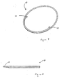
Figure 7 is a perspective top view of an exemplary spring;
Figure 8 is a perspective side view of an exemplary spring;
Figure 9 is a depiction of an exemplary fitting between an exemplary coupling
body and an exemplary nut;
Figure 10 is a cross-sectional view of exemplary embodiments of the coupling
body, nut, and sleeve engaged with each other;
Figure 11 is an exemplary embodiment of the fitting device particularly depicting
a side view of an exemplary sleeve comprising multiple sleeve segments; and
Figure 12 is a perspective cross-sectional view of an exemplary attachment
between an exemplary fitting device and an exemplary tubing.
DETAILED DESCRIPTION OF THE INVENTION
Referring to Figure 1, an exemplary fitting contains a coupling body 1, a nut 2,
and a sleeve 3. A corrugated tubing 4 is inserted into nut 2, which contains sleeve 3. Nut
2 is threadedly engaged with coupling body 1 and tightened thereby compressing a
protruding section of corrugated tubing 4, generally one full corrugation, creating a seal.
In its preferred configuration and as depicted in Figures 1, 9 and 12, sleeve 3, nut 2, and
coupling body 1 are pre-assembled into one unit 31. Preferably, the prepared end of a
section of corrugated tubing 4 is inserted into the pre-assembled unit and nut 2 is
tightened, thereby creating a gas-tight seal.
An exemplary coupling body is depicted in Figure 2. Referring to Figure 2, a
coupling body 1 comprises an axial through bore 5 and a notched shoulder 6 that contains
a sealing surface. An inner surface of through bore 5 comprises a partially threaded
interior portion 7 and an unthreaded interior portion 8, which is of a smaller diameter
than partially threaded interior portion 7. Notched shoulder 6 of coupling body I
separates partially threaded interior portion 7 from unthreaded interior portion 8.
Partially threaded interior portion 7 comprises an unthreaded portion 7a, which abuts
notched shoulder 6. Notched shoulder 6 prevents the tubing, e.g., the corrugated tubing
(not shown), from passing completely through through bore 5 of coupling body 1 and
creates the seal surface. In its preferred configuration, coupling body 1 also contains a
threaded exterior portion 10 to which tubing or a fitting may be attached, and a radial
flange 10a preferably comprising a hexagonal flats portion.
In its preferred configuration, exterior radial flange 10a of coupling body I
comprises an angular surface 10b for staking. Staking functions as a stop to prevent the
nut from disengaging from the coupling body and evenly distributes the force on the
interior threads of the coupling body when engaged with the threads of the nut. Although
the number and position of the stakings may vary, in its preferred configuration, the
coupling body contains one or two stakings, wherein multiple stakings are at
approximately 120-degree angles from each other.
Still referring to Figure 2, notched shoulder 6 of coupling body 1 comprises
several annular surfaces. For example, a first surface 11 is approximately perpendicular
to partially threaded interior portion 7 of through bore 5. First surface 11 narrows the
diameter of through bore 5. A second surface 12 which is approximately perpendicular
to first surface 11, and which is approximately parallel to partially threaded interior
portion 7 of through bore 5. Notched shoulder 6 further comprises a third surface 13,
which is parallel to first surface 11 and further narrows the diameter of through bore 5.
Third surface 13 contains a flat portion 13a and an annular lip 9. Annular lip 9 preferably
protrudes towards partially threaded interior portion 7 (the left side of coupling body 1 as
depicted in Figure 2). Annular lip 9 assists in creating the sealing surface and is an
integral part of the sealing process. Flat portion 13a of third surface 13 functions as an
open relief surface preventing excessive crimping of the tube upon overtorqueing which
could result in a fracture of the tube and a leak.
An exemplary nut is depicted in Figures 3 and 7. wherein Figure 4 depicts a cross-section
of the nut, and Figure 3 depicts an elevational view of the nut. Referring to
Figures 3 and 7, a nut 2 contains a threaded exterior portion 14, referred to as the nut's
threaded end, that is threadedly engageable with the internally threaded portion of the
coupling body (reference numeral 7 in Figure 1). Nut 2 also contains a radial flange 15.
referred to as the nut's flange end, having a flats portion 15a that may be tightened with a
wrench or other tool during installation. Preferably, flats portion 15a is hexagonal. Nut 2
contains an axial through bore 16, which receives the sleeve (not shown) and the
corrugated tubing (not shown). Through bore 16 contains a tapered inner surface 17 that
begins with an annular lip 18 that protrudes into through bore 16 at threaded end 14.
Tapered inner surface 17 gradually narrows reducing the diameter of through bore 16 and
then stops narrowing leaving a section of straight through bore 19 which continues
through flange end 15. While in its preferred configuration the coupling contains a
threaded nut, other fasteners may be used. Such fasteners may include, for example, a
saw tooth or gear design in which teeth or gears on the exterior surface of the fastener
join with gears or teeth on the interior surface of the coupling body.
An exemplary sleeve is depicted in Figures 5 and 6. Referring to Figure 5, in its
preferred configuration, a sleeve 3 is comprised of four separate segments 22 (only three
segments shown). While in its preferred configuration, the sleeve is divided into four
segments, the sleeve may comprise more than four segments, for example up to 8
segments. The geometry of corrugated tubing, however, is such that with four sleeve
segments it is easier to remove the tubing from the fitting, and the cost to manufacture the
sleeve is reduced as compared to a sleeve comprised of more than four segments.
Alternatively, the sleeve could be comprised of fewer than four segments.
Referring to Figures 5 and 6, each segment 22 contains an inner surface 23 and an
outer surface 24. Inner surface 23 of each segment 22 has a projection 25. As shown in
Figures 4 and 5, in an exemplary embodiment, when segments 22 are combined and
compressed, they become annular and are of a diameter smaller than that of a corrugated
tubing 4's ridges 51 but larger than tube 4's grooves 50. For example, as depicted in
Figure 12, when corrugated tubing 4 is inserted into sleeve 3, projection 25 fits into a
groove 50 of corrugated tubing 4, thereby removably securing sleeve 3 to corrugated
tubing 4.
Returning to Figures 5 and 6, inner surface 23 of each segment 22 also contains a
recessed groove 27 which, when the segments are connected, becomes annular. As
shown in an exemplary embodiment in Figure 10, a spring 70 fits into recessed groove
27. Spring 70 exerts an outward force on each of segment 22.
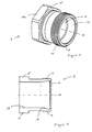
An exemplary spring is shown in Figures 10 and 11. Referring to Figures 10 and
11, in its preferred configuration the spring is an annular spring 40. The terminal ends 41
of spring 40 are bent inward toward the center of annular spring 40. Though not
required, it is preferred that the terminal ends overlap each other, such as is shown in
Figures 10 and 11. The bent ends of annular spring 40 prevent the ends from becoming
lodged between the sleeve segments upon tightening the nut, preventing the fitting from
functioning properly. While in its preferred configuration the ends are bent inward, the
ends of the spring and the spring itself may be shaped differently.
Referring back to Figure 6, each of segments 22 preferably comprises tapered
portions 29 of their outer surfaces 24. Tapered portions 29 narrow the thickness of the
sleeve gradually toward a proximal end 20 of the sleeve. Tapered portions 29 begin near
a distal end 21 of segment 22 and begin with a shoulder 30a. Tapered portions 29
terminate at proximal end 20 with a protruding lip 30.
Still referring to Figure 6, in its preferred configuration, protruding lip 30 extends
along the entire length of proximal end 20 of the sleeve. However, in an alternative
embodiment, at least one of the segments may comprises a rectangular void at the
proximal end, such that a portion of the protruding lip is cut away thereby dividing the
protruding lip into two arcuate lip portions. Preferably, the cut away portion is centered
such that the arcuate lip portions are equal in width.
The tapered portion of the sleeve's outer surface (e.g., reference numeral 29 in
Figure 6) corresponds to the tapered interior surface of the nut (e.g., reference numeral 17
in Figure 4), thereby, facilitating radial movement of the sleeve segments, locking them
into the proper position in the tube's groove when the nut is tightened. The tapered
surfaces of the nut and sleeve form an approximately supplementary angle when the
surfaces are brought into contact with one another.
In its preferred configuration, and as depicted in Figure 6. each of segments 22
also has tapered sides 20a. Tapered sides 20a begin to taper at shoulder 30a and cease
tapering at protruding lip 30. In its preferred configuration, the sides taper at an angle of
approximately 10 degrees relative to proximal end 20 of segment 22. The purpose of
tapered sides 20a is to prevent overlap of the sleeve segments when the tubing is not in
the fitting.
In its preferred configuration the sleeve is manufactured from stainless steel for
strength and to resist corrosion. The sleeve may also be manufactured from brass or any
other material that has suitable strength and corrosive properties. Preferably, the sleeve is
plated with silver to decrease friction and increase lubricity. Preferably, the silver plating
is done as a last step in the manufacturing process. The sleeve may also be coated with a
suitable lubricant such as a dry film type lubricant. Lubrication prevents seizing or
galling of contacting materials under load.
The fitting is formed by combining a body, a nut, and a sleeve, such as those
described herein. For example, the threaded exterior portion of the nut (reference
numeral 14 in Figure 4) may be engaged with the partially threaded interior portion of the
coupling body (reference numeral 7 in Figure 2) to achieve an exemplary fitting as
disclosed in Figure 9. Here then, a surface view of a single fitting unit 31 comprises nut
2 joined to coupling body 1 such that an interior portion of the distal end of nut 2 is
disposed within a portion of coupling body 1.
Referring to Figures 6 and 9, each segment 22 forming the sleeve preferably
comprises a proximal end 20 that receives corrugated tubing 4, and a distal end 21 which
is inserted into nut 2 and coupling body 3. Referring to Figure 9, an exemplary fitting
comprises a distal end of nut 2 inserted into coupling body 1.
Referring to Figures 4, 9, and 12, upon further tightening nut 2, tapered inner
surface 17 of nut 2 contacts and moves about tapered outer surface 29 of the sleeve
creating a wedging action forcing nut 2 and the sleeve toward notched shoulder 6 of
coupling body 1. As shown in Figure 10, shoulder 30a of the sleeve prevents tapered
inner surface 17 of nut 2 from sliding over tapered surface 29 of the sleeve and facilitates
the movement of the sleeve toward notched shoulder 6 of coupling body 1 creating the
seal. This is principally accomplished by shoulder 30a of the sleeve coming into contact
with annular lip 18 of nut 2. Similarly, protruding lip 30 on tapered portion 29 of the
sleeve prevents nut 2 from completely detaching from the sleeve upon loosening of nut 2.
This is primarily accomplished by protruding lip 30 of the sleeve coming into contact
with annular lip 18 on tapered inner surface 17 of nut 2.
Tapered surfaces 17, 29 of the sleeve and nut 2 respectively create a wedging
action when nut 2 is tightened. This has the effect of compressing all four segments 22 of
the sleeve and forcing nut 2 and the sleeve further into axial through bore 5 of coupling
body 1 toward notched shoulder 6 of coupling body 1 until projection 25 and corrugated
tubing (not shown) contact notched shoulder 6.
In its preferred configuration and as depicted in Figures 1 and 4, sleeve 3, nut 2,
and coupling body 1 are pre-assembled into a single fitting 31. To use the fitting in its
preferred embodiment, a corrugated tubing 4 is inserted into the pre-assembled fitting 31
through a proximal end of nut 2. Nut 2 is then tightened.
However, as a preliminary step, the corrugated tubing is preferably prepared for
insertion. This may be accomplished by removing the outer coating or jacket of the tube
to expose three or four corrugations. The tube end may then be cut to provide as clean a
cut as possible.
Figure 12 depicts an exemplary placement of the corrugated tubing into a fitting.
Referring to Figures 4, 6, and 9, a corrugated tubing 4 is inserted into proximal end 20 of
the sleeve, wherein the sleeve is contained within coupling body 1. Projections 25 on the
respective inner surfaces of the annular sleeve fit into grooves 50 in corrugated tubing 4.
A portion of tubing 52, generally one full corrugation, protrudes from the end of the
sleeve within coupling body 1.
As torque is applied to the flats portion of nut 2's radial flange 15, tapered inner
surface 17 of nut 2 slides over the complementary tapered portion 29 of sleeve 3. This
has the effect of compressing all segments 22 of sleeve 3 and forcing nut 2 and sleeve 3
further into axial through bore 5 of coupling body 1 toward notched shoulder 6 of
coupling body 1 until the sleeves' projections 25 and corrugated tubing 4 contact notched
shoulder 6. The compression of segments 22 causes the portion of corrugated tubing 52
protruding from sleeve 3 to be compressed against notched shoulder 6 of coupling body
1.
Referring to Figures 2, 4, 6, and 9, portion of tubing 52 is compressed against
second 12 and third surfaces 13 and annular lip 9 of notched shoulder 6 of coupling body
1 creating a tight seal. Projection 25 of the sleeve may be shaped to fit within second 12
and third 13 surfaces of notched shoulder 6 of the coupling body 1 thereby effectively
concentrating the sealing load and assuring a reliable tight seal.
To remove the coupling, torque is applied to flats portion 15a of nut 2's radial
flange 15, thereby loosening nut 2. Loosening nut 2 causes tapered inner portion 17 of
nut 2 to slide over the complementary tapered portion 29 of the sleeve allowing inner
spring 70 to expand and exert an outward force on segments 22. Corrugated tubing 4
may then be removed. Segments 22 will return to their pre-sealing state, as they do not
deform in the sealing process as do conventional sleeves. The fitting may then be reused.
Additionally, in its preferred configuration, the fitting comprises a removable
plastic end plug. The end plug assures that the fitting is kept clean and devoid of
contaminants, and is ready for installation of the tubing upon removal of the plug.
Other less effective variations on the inventive fitting are possible. These include
variations in which the body containing the seal surface is configured such that a fastener
may fit over the body, as opposed to into the body, pushing the sleeve toward the
shoulder until it has compressed a section of corrugated tubing against the shoulder.
Additionally, in configurations such as this the fastener may be fastened to the body
through the use of a sawtooth or gear design in which teeth or gears on the interior
surface of the fastener join with gears or teeth on the exterior surface of the body. The
functionality of a configuration such as this is reduced as the fastener may not be easily
detached from the body.
The fitting device disclosed herein provides several advantages over the prior art.
For example, the fitting device disclosed herein, the sleeve does not need to be manually
compressed/reduced to fit into the coupling body as the coupling components are pre-assembled.
To use the inventive fitting, one must simply insert the prepared end of the
tubing into the fitting device and then tighten the nut. Should there be a variation in the
tube corrugation, there is sufficient radial force created by the wedging action between
the nut and sleeve when the nut is tightened to force the rib on the sleeve segments into
the tube corrugation.
Although the invention has been shown and described with respect to its preferred
embodiment, those skilled in the art should understand that the foregoing and various
other changes, omissions, and additions in the form and detail may be made without
departing from the spirit and scope of the invention.