EP2278204A2 - Screw connection for corrugated pipe - Google Patents
Screw connection for corrugated pipe Download PDFInfo
- Publication number
- EP2278204A2 EP2278204A2 EP10169720A EP10169720A EP2278204A2 EP 2278204 A2 EP2278204 A2 EP 2278204A2 EP 10169720 A EP10169720 A EP 10169720A EP 10169720 A EP10169720 A EP 10169720A EP 2278204 A2 EP2278204 A2 EP 2278204A2
- Authority
- EP
- European Patent Office
- Prior art keywords
- clamping
- clamping ring
- corrugated pipe
- base body
- connection fitting
- Prior art date
- Legal status (The legal status is an assumption and is not a legal conclusion. Google has not performed a legal analysis and makes no representation as to the accuracy of the status listed.)
- Granted
Links
Images


Classifications
-
- F—MECHANICAL ENGINEERING; LIGHTING; HEATING; WEAPONS; BLASTING
- F16—ENGINEERING ELEMENTS AND UNITS; GENERAL MEASURES FOR PRODUCING AND MAINTAINING EFFECTIVE FUNCTIONING OF MACHINES OR INSTALLATIONS; THERMAL INSULATION IN GENERAL
- F16L—PIPES; JOINTS OR FITTINGS FOR PIPES; SUPPORTS FOR PIPES, CABLES OR PROTECTIVE TUBING; MEANS FOR THERMAL INSULATION IN GENERAL
- F16L25/00—Constructive types of pipe joints not provided for in groups F16L13/00 - F16L23/00 ; Details of pipe joints not otherwise provided for, e.g. electrically conducting or insulating means
- F16L25/0036—Joints for corrugated pipes
-
- F—MECHANICAL ENGINEERING; LIGHTING; HEATING; WEAPONS; BLASTING
- F16—ENGINEERING ELEMENTS AND UNITS; GENERAL MEASURES FOR PRODUCING AND MAINTAINING EFFECTIVE FUNCTIONING OF MACHINES OR INSTALLATIONS; THERMAL INSULATION IN GENERAL
- F16L—PIPES; JOINTS OR FITTINGS FOR PIPES; SUPPORTS FOR PIPES, CABLES OR PROTECTIVE TUBING; MEANS FOR THERMAL INSULATION IN GENERAL
- F16L2201/00—Special arrangements for pipe couplings
- F16L2201/10—Indicators for correct coupling
-
- F—MECHANICAL ENGINEERING; LIGHTING; HEATING; WEAPONS; BLASTING
- F24—HEATING; RANGES; VENTILATING
- F24S—SOLAR HEAT COLLECTORS; SOLAR HEAT SYSTEMS
- F24S80/00—Details, accessories or component parts of solar heat collectors not provided for in groups F24S10/00-F24S70/00
- F24S80/30—Arrangements for connecting the fluid circuits of solar collectors with each other or with other components, e.g. pipe connections; Fluid distributing means, e.g. headers
Definitions
- the invention relates to a corrugated pipe connection fitting, comprising a base body with a corrugated pipe side connection and a clamping ring which can be set up by a clamping device with respect to the base body, equipped with at least one driver for engaging a corrugated pipe in a corrugation trough, the corrugated pipe side connection of the main body having a first annular clamping surface and the clamping ring has a second clamping surface arranged to cooperate with this first clamping surface and both clamping surfaces are arranged so that a vertex of a corrugated pipe arranged between them is compressed in the process of connecting the corrugated pipe to the basic body.
- Corrugated pipes are typically metal pipes, for example of steel, also of stainless steel or copper. Such tubes are used to compensate for changes in length and / or angle, such as in solar technology between a solar module and a heat pump.
- a corrugated tube connector designed as a screw connector is known in which a deformation of the free end of the corrugated tube to achieve a metallic seal is provided for sealing the corrugated tube relative to the main body of the connector.
- this known corrugated tube connection connector has a retaining body formed from two shells, on the inside of which a protruding Verklamm ceremoniessrippe is formed as a driver.
- This Verklamm ceremoniessrippe serves to engage in the following on the end of the corrugated pipe first valley of the corrugated pipe.
- this retaining body can be positively connected in a longitudinal axial direction to a corrugated pipe.
- a union nut located on the corrugated tube retaining body is bolted to the base body.
- the first vertex of the corrugated tube is pressed against serving as a first clamping surface sealing cone of the body to create the metallic seal and compressed in this direction, thus transformed.
- the retaining body formed of two shells, which, when connected to the corrugated pipe, can be addressed as a clamping ring, via a second clamping surface.
- WO 97/42442 A1 Another Wellrohran gleichschraubung has become known, which constructed on the principle of action, as described above. Unlike this one has the WO 97/42442 A1 became known corrugated tube connection fitting via a one-piece clamping ring which is pushed onto the free end of the corrugated tube. Pointing in the direction of the main body of this clamping ring has a plurality of individual, each separated by a gap clamping ring segments with an intended to engage in a valley of the corrugated pipe driver. The clamping ring segments are elastically movable in the radial direction, so that a corrugated tube can be pushed through the arrangement of the clamping ring segments by utilizing these elastic properties.
- a union nut as a clamping device summarizes the clamping ring segments of the clamping ring, which protrudes with its the clamping ring segments cohesive portion of the rear end of the union nut.
- the clamping ring segments each have a control head, which rests against a setting backdrop of the union nut.
- the Stellkulisse is inclined to the corrugated pipe end of the union nut formed so that when screwing the nut on the body, the clamping ring segments are pressed with their drivers in the radial direction in a valley of the corrugated pipe.
- the Stellkulisse continues in an abutment pocket for receiving the rear portion of the actuating head, whereby the clamping ring segments undergoes the necessary abutment for applying the applied to create the desired metallic seal force.
- the invention is therefore the object of developing a corrugated pipe connection fitting with the features of the preamble of claim 1 such that not only the handling of corrugated pipe connection fitting is kept simple in the assembly of a corrugated tube, but also the formation of the seal between corrugated tube and body is improved.
- This corrugated pipe connection has a concentric with the body-side clamping surface - the first clamping surface - arranged adjusting body, between which and the clamping surface a circumferential Klemmringnut is provided.
- This serves to receive the front, pointing to the base body portion of the clamping ring, which, when engaging with its front portion in this, with its outer side on serving as an abutment groove wall of the Klemmringnut - an abutment surface - is supported. So that the front portion of the clamping ring can be inserted into the Klemmringnut, the material thickness in the region of its front portion is smaller than the inside diameter of at least the mouth region of the Klemmringnut.
- the adjusting body of this corrugated pipe connection fitting has a stop for the front, pointing to the base end of the clamping ring on which stop the clamping ring rests with its front end, before the clamping device is operated for clamping the end of the connected corrugated pipe.
- the clamping ring has a longitudinal axial extension, starting from its driver, which engages over a crest of a corrugated tube to be reshaped at its clamping surface in the direction of the main body.
- a clamping ring is preferably an open through a slot annular body. This is held according to an embodiment in a clamping ring chamber of the clamping device preferably designed as a union nut.
- the clamping ring is held so far widened within the clamping ring chamber of the clamping device that the typically serving as a clamping device union nut, without having to widen the clamping ring, can be pushed onto the connection end of a corrugated tube.
- the inner diameter of the clamping ring so that this when inserting a corrugated pipe is slightly widened by the then slightly larger in diameter vertex to give a fitter a haptic feedback about when the driver of the clamping ring is located in a trough.
- a corrugated pipe connection fitting 1 comprises a main body 2, a clamping ring 3 and a union nut 4 as a clamping device.
- the main body 2 is typically part of an installation to which a corrugated tube 5 is to be connected.
- the main body 2 carries the connection side and thus facing the corrugated pipe 5, an external thread 6, on which the union nut 4 can be screwed with its internal thread.
- the clamping ring 3 is, as shown in the illustration of FIG. 2 recognizable, held in a pre-assembly within a clamping ring chamber 7 of the union nut 4.
- the clamping ring 3 is an open by a slot S ring body in the manner of a snap ring (see FIG. 1 ), which has a certain elasticity in the radial direction.
- the clamping ring 3 can be inserted through the internal thread 8 of the union nut 4 into the clamping ring chamber 7, in which the clamping ring 3 widens due to its elastic properties and henceforth is held captive.
- the union nut 4 will be supplied with the clamping ring 3 contained in its clamping ring chamber 7. If the base body 2 is already part of an installation, therefore, only one union nut 4 and the free end of the corrugated pipe 5 are to be handled by a fitter for connecting the corrugated pipe 5 to the installation.
- the clamping ring 3 carries a radially inwardly projecting bead as a driver 9. This is used to engage in a valley of the connected corrugated pipe 5.
- the facing the corrugated pipe 5 side 10 of the clamping ring 3 is curved and can serve as a footprint for inserting the free end serve the corrugated pipe 5, the clamping ring 3 should be less dilated, in contrast to the representation in the figures.
- the clamping ring 3 is designed so that the limited by the driver 9 inner diameter of the clamping ring 3 is greater than the maximum outer diameter of the corrugated pipe 5 is.
- the radially outwardly facing side 11 of the clamping ring 3 is convexly curved.
- the clamping ring 3 In the direction of the base body 2, the clamping ring 3 has a stop surface 12.
- the adjacent to the driver 9, inclined in the direction of the base body 2 facing surface serves as a clamping surface 13.
- the clamping surface 13 merges into a cylindrical surface portion 14, which in turn at an angle the stop surface 12 is adjacent.
- union nut 4 When serving as a clamping device union nut 4 is a longitudinal axis of the same inclined, tapered to the rear output of the union nut 4 tapered footprint 15 for corrugated outlet side boundary of the clamping ring chamber. 7
- the main body 2 has at its corrugated pipe-side connection 16 via a clamping surface 17, which is part of the passage channel 18 enclosing mouth projection 19.
- the mouth projection 19 is rounded in the direction of the corrugated pipe 5, wherein the clamping surface 17 is inclined to the longitudinal axis of the base body 2 and is located on the outwardly facing side of the mouth projection 19.
- the inclination of the clamping surface 17 relative to the longitudinal axis of the threaded connection is inclined at a greater angle than the clamping surface 13 of the clamping ring 3.
- the base body 2 Concentric with the mouth projection 19, the base body 2 has an annular actuating body 20, which is arranged concentrically to the mouth projection 19, leaving a clamping ring groove 21 in the radial direction at a distance from the mouth projection 19.
- the clear width of the mouth of Klemmringnut 21 is greater than that Material thickness of the clamping ring 3 in the region of its tapered front, the stop surface 12 bearing completion. With an appropriate arrangement of the clamping ring 3, this can thus be introduced into the Klemmringnut 21 with its front, the surface portion 14 comprehensive section.
- the clear width of the clamping groove 21 itself In contrast, corresponds essentially to the material thickness of the clamping ring 3 in the region of its front end.
- FIG. 2 shows the required for connecting the corrugated pipe 5 to the base body 2 items in a first mounting position to each other.
- the union nut 4 is screwed with its internal thread 8 on the external thread 6 of the base body 2.
- this pre-assembly which typically represents the delivery arrangement of the items of the corrugated pipe connection fitting 1
- the corrugated pipe 5 is inserted with its free end. This condition is in FIG. 2 shown.
- the union nut 4 is moved in the following to the base body 2 in the axial direction below.
- the clamping ring 3 is positively connected for subsequent entrainment of the corrugated pipe 5 to this.
- the clamping ring 3 is not moved in the axial direction, but only, as in FIG. 3 indicated by the direction of the arrow, reduced only in terms of its diameter. This radial movement takes place until the stop surface 12 has been moved past the end face 22 of the adjusting body 20 of the main body 2 and then in a second phase of the front portion of the clamping ring 3 can be pressed into the Klemmringnut 21.
- FIG. 4 Visible, the front portion of the clamping ring 3 has been introduced into the Klemmringnut 21, wherein by the footprint 23 of the actuating body 20, a special clamping pressure, on the front portion of the outer side 11 of the clamping ring 3 is applied.
- a clamping pressure on the clamping ring 3 is effected not only by the footprint 15 of the union nut 4 and thus from a direction lying in the direction behind the apex 24 direction, but also by the footprint 23, and that in front of a mounting direction the apex 24 located direction.
- FIG. 4a shows the arrangement of FIG. 4 , in which the force introduction direction K is registered, with which the force is introduced from the clamping ring 3 in the apex 24 of the corrugated tube 25.
- the location of the highest force is located immediately adjacent to the apex 24 of the corrugated tube 5 and initiates the clamping force in the radial direction in the apex 24 a. It can be clearly seen that the vectorial radial component greater than the vectorial axial portion.
- the conclusion of the clamping ring 3 facing the corrugated tube 5 is flush or approximately flush with the rear end of the union nut 4. If desired, this surface of the ring body can be marked in color, so that the achievement of the intended Verschraubungsgrades is readily apparent to a fitter. Moreover, it is visible in the above-described concept for an installer that the slot S has been completely or at least substantially completely closed in the course of the screwing.
- the inclination of the clamp ring-side clamping surface is slightly less inclined than the inclination of the body-side clamping surface at the point where it is provided as an abutment for the formation of the apex end of a corrugated tube.
- the clamping gap located between the clamping surfaces is tapered outwards.
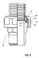
- FIG. 5 shows a further corrugated pipe connection fitting 26, which is basically constructed as well as the corrugated pipe connection fitting 1 of FIGS. 1 to 4 ,
- the corrugated pipe connection fitting 26 differs from the corrugated pipe connection fitting 1 with regard to the configuration of its clamping ring 27 and the outlet end of the union nut 28.
- the clamping ring 27 is mirror-symmetrical in this embodiment. As a result, assembly errors are avoided.
- the cap nut 28 carries adjacent to its conically inclined footprint 30 has an inwardly projecting flange 31, whose inner, facing the base body side serves as a rear stop for the rear end face 32 of the clamping ring 27.
- the clamping ring 27 abuts against the flange 31, the clamping ring 27 experiences a distortion, with the consequence that the forces acting on the apex of the corrugated pipe radial forces are increased. This is due to the support of the engaging in the Klemmringnut 32 and is based on the abutment surface 33 of the actuating body clamping ring portion.
- FIG. 5 shows the connected to the corrugated pipe fitting 26 corrugated pipe. In this pose the same and in the case of a twist, as described above, also acting in the radial direction more clamping forces, as this to the embodiment of FIGS. 1 to 4 has been described.
- FIG. 6 Another corrugated pipe connection 26.1 is in FIG. 6 shown.
- the corrugated pipe connection fitting 26.1 corresponds to that of the embodiment of FIG. 5 with the difference that the inclined footprint 30.1 of the union nut 28.1 is continued up to the corrugated tube side opening, thus an inwardly projecting flange is not provided.
- the contact arrangement of the clamping ring 27.1 due to the inclination of the footprint 30.1 this applied when screwing the nut 30.1 with radial forces.
- the main body, the clamping rings and the union nuts are made of a brass alloy.
Landscapes
- Engineering & Computer Science (AREA)
- General Engineering & Computer Science (AREA)
- Mechanical Engineering (AREA)
- Clamps And Clips (AREA)
- Joints That Cut Off Fluids, And Hose Joints (AREA)
- Flanged Joints, Insulating Joints, And Other Joints (AREA)
Abstract
Description
Die Erfindung betrifft eine Wellrohranschlussverschraubung, umfassend einen Grundkörper mit einem wellrohrseitigem Anschluss und einen durch eine Spanneinrichtung gegenüber dem Grundkörper einrichtbaren Klemmring, ausgestattet mit zumindest einem zum Anschließen eines Wellrohres in ein Wellental desselben eingreifenden Mitnehmer, wobei der wellrohrseitige Anschluss des Grundkörpers eine erste ringförmige Klemmfläche und der Klemmring eine zum Zusammenwirken mit dieser ersten Klemmfläche angeordnete zweite Klemmfläche aufweist und beide Klemmflächen angeordnet sind, damit ein zwischen diesen angeordneter Scheitel eines Wellrohres bei dem Vorgang des Anschließens des Wellrohres an den Grundkörper zusammengedrückt wird.The invention relates to a corrugated pipe connection fitting, comprising a base body with a corrugated pipe side connection and a clamping ring which can be set up by a clamping device with respect to the base body, equipped with at least one driver for engaging a corrugated pipe in a corrugation trough, the corrugated pipe side connection of the main body having a first annular clamping surface and the clamping ring has a second clamping surface arranged to cooperate with this first clamping surface and both clamping surfaces are arranged so that a vertex of a corrugated pipe arranged between them is compressed in the process of connecting the corrugated pipe to the basic body.
Bei Wellrohren handelt es sich typischerweise um Metallrohre, beispielsweise aus Stahl, auch aus Edelstahl oder Kupfer. Eingesetzt werden derartige Rohre zur Kompensation von Längen- und/oder Winkeländerungen, etwa in der Solartechnik zwischen einem Solarmodul und einer Wärmepumpe. Aus
Aus
Ausgehend von diesem diskutierten Stand der Technik liegt der Erfindung daher die Aufgabe zugrunde, eine Wellrohranschlussverschraubung mit den Merkmalen des Oberbegriffs des Anspruchs 1 dergestalt weiterzubilden, dass nicht nur die Handhabung der Wellrohranschlussverschraubung bei der Montage eines Wellrohres einfach gehalten ist, sondern zudem die Ausbildung der Dichtung zwischen Wellrohr und Grundkörper verbessert ist.Based on this discussed prior art, the invention is therefore the object of developing a corrugated pipe connection fitting with the features of the preamble of
Diese Aufgabe wird erfindungsgemäß durch eine eingangs genannte, gattungsgemäße Wellrohrverschraubung gelöst, bei der die Klemmfläche des Grundkörpers Teil eines einen Durchgangskanal einfassenden Mündungsvorsprunges ist, dass die Klemmfläche zur Längsachse des Grundkörpers geneigt ist und sich an einer nach außen weisenden Seite des Mündungsvorsprunges befindet und bei der der Grundkörper konzentrisch zu der Längsachse seiner Klemmfläche unter Belassung einer Klemmringnut einen ringförmigen Stellkörper mit einer vorderen Anschlagfläche für den Klemmring und mit einer Widerlagerfläche aufweist, an dem sich der Klemmring, wenn mit seinem vorderen Endabschnitt in die Klemmringnut eingeführt, mit einem Abschnitt seiner Außenseite abstützt.This object is achieved by an aforementioned generic Wellrohrverschraubung in which the clamping surface of the body is part of a passage channel enclosing mouth projection, that the clamping surface is inclined to the longitudinal axis of the body and is located on an outwardly facing side of the mouth projection and in the the base body concentric with the longitudinal axis of its clamping surface, leaving a Klemmringnut having an annular actuating body with a front stop surface for the clamping ring and an abutment surface on which the clamping ring when inserted with its front end portion in the Klemmringnut, supported with a portion of its outer side ,
Diese Wellrohranschlussverschraubung verfügt über einen konzentrisch zu der grundkörperseitigen Klemmfläche - der ersten Klemmfläche - angeordneten Stellkörper, wobei zwischen diesem und der Klemmfläche eine umlaufende Klemmringnut vorgesehen ist. Diese dient zur Aufnahme des vorderen, zum Grundkörper weisenden Abschnittes des Klemmringes, der sich, wenn mit seinem vorderen Abschnitt in diese eingreifend, mit seiner Außenseite an einer als Widerlager dienenden Nutenwand der Klemmringnut - einer Widerlagerfläche - abstützt. Damit der vordere Abschnitt des Klemmringes in die Klemmringnut eingeführt werden kann, ist dessen Materialstärke im Bereich seines vorderen Abschnittes geringer als die lichte Weite zumindest des Mündungsbereiches der Klemmringnut. Durch die grundkörperseitige Anordnung des Stellkörpers mit seinem auf die Außenseite des Klemmringes in seinem vorderen Abschnitt wirkenden Widerlager wirkt über die Klemmfläche des Klemmringes auf einen zwischen beiden Klemmflächen angeordneten Scheitel eines Wellrohres nicht nur eine aus der Betätigung der beispielsweise als Überwurfmutter konzipierten Spanneinrichtung in Richtung zum Grundkörper weisende Klemmkraftkomponente, sondern vielmehr bei entsprechender Ausgestaltung des Klemmringes eine durch das Widerlager des Stellkörpers dieser sogar im gewissen Maße Entgegengerichtete, sobald der vordere Abschnitt des Klemmringes in die Klemmringnut eingeführt ist. Bei der beanspruchten Wellrohranschlussverschraubung erfährt der Klemmring eine nicht unerhebliche radiale Klemmkraftkomponente mit dem Ergebnis, dass auf den zwischen den beiden Klemmflächen befindlichen Wellrohrscheitel Klemmkräfte aus radialen Richtungen wirken. Aufgrund des Vorsehens der ersten Klemmfläche an der Außenseite eines den Durchgangskanal einfassenden Mündungsvorsprunges wird der zwischen den Klemmflächen eingeklemmte Scheitel durch eine nicht im Wesentlichen axiale Klemmkraft verklemmt. Bei dieser Wellrohranschlussverschraubung steht die Umformung des zwischen den beiden Klemmflächen befindlichen Wellrohrscheitels zum Ausbilden einer metallischen Dichtung im Vordergrund. Dabei ist vorgesehen, dass die über den Klemmring aufgebrachte Klemmkraft auf den zwischen den beiden Klemmflächen befindlichen Scheitel bzw. scheitelnahen Bereich konzentriert ist. Durch die Konzentration der angelegten Kraft auf die Umformung des Scheitels gelingt dieses jedoch mit den üblichen, zur Verfügung stehenden Kräften. Die vorbeschriebene Kraftkonzentration als Spannungsspitze begünstigt das Ausbilden einer metallischen Dichtung in diesem Bereich.This corrugated pipe connection has a concentric with the body-side clamping surface - the first clamping surface - arranged adjusting body, between which and the clamping surface a circumferential Klemmringnut is provided. This serves to receive the front, pointing to the base body portion of the clamping ring, which, when engaging with its front portion in this, with its outer side on serving as an abutment groove wall of the Klemmringnut - an abutment surface - is supported. So that the front portion of the clamping ring can be inserted into the Klemmringnut, the material thickness in the region of its front portion is smaller than the inside diameter of at least the mouth region of the Klemmringnut. Due to the body-side arrangement of the actuating body with its acting on the outside of the clamping ring in its front section abutment acts on the clamping surface of the clamping ring on a arranged between two clamping surfaces crest of a corrugated pipe not only one of the operation of, for example, designed as a union clamping device towards the body pointing clamping force component, but rather with appropriate design of the clamping ring by the abutment of the actuating body of this even to some extent opposite, as soon as the front portion of the clamping ring is inserted into the Klemmringnut. In the claimed Wellrohranschlussverschraubung undergoes the clamping ring a not inconsiderable radial clamping force component with the result that act on the located between the two clamping surfaces corrugated pipe vertex clamping forces from radial directions. Due to the provision of the first clamping surface on the outside of the passage channel enclosing mouth projection of the clamped between the clamping surfaces vertex is clamped by a non-substantially axial clamping force. In this corrugated tube connection fitting, the forming of the corrugated pipe apex located between the two clamping surfaces to form a metallic seal in the foreground. It is provided that the clamping force applied via the clamping ring is concentrated on the vertex or crest-near region located between the two clamping surfaces. By concentrating the applied force on the deformation of the apex, however, this succeeds with the usual, available forces. The above-described force concentration as a stress peak favors the formation of a metallic seal in this area.
Der Stellkörper dieser Wellrohranschlussverschraubung verfügt über einen Anschlag für den vorderen, zum Grundkörper weisenden Abschluss des Klemmringes, an welchem Anschlag der Klemmring mit seiner vorderen Stirnseite anliegt, bevor die Spanneinrichtung zum Einspannen des Endes des daran angeschlossenen Wellrohres betätigt wird. Durch diesen Anschlag ist der Klemmring, wenn die Spanneinrichtung, beispielsweise die Überwurfmutter in axialer Richtung in Richtung zum Grundkörper bewegt wird, von der axialen Bewegung entkoppelt, so dass während des Aufschraubens der Überwurfmutter für einen bestimmten Bewegungsabschnitt die Überwurfmutter ohne Mitnahme des Klemmringes in axialer Richtung zum Grundkörper hin bewegt wird. In dieser Anschlaganordnung zwischen Klemmring und Stellkörper wird, wie nachstehend beschreiben, bei einer axialen Bewegung der Spanneinrichtung der Durchmesser des Klemmringes verringert. In Folge der vorbeschriebenen Bewegungsentkopplung kann der Prozess des Zusammendrückens eines zwischen den beiden Klemmflächen befindlichen Scheitels eines Wellrohres in Abhängigkeit von der relativen Anordnung von Spanneinrichtung und Klemmring zueinander gesteuert werden, und zwar der Gestalt, dass im Zuge des Spannens der Spanneinrichtung zunächst der Klemmring mit seinem Mitnehmer in ein Wellental eingebracht wird, ohne dass in dieser ersten Phase die beiden Klemmflächen aufeinander zu bewegt werden. Eine axiale Bewegung des Klemmringes erfolgt erst, wenn der Mitnehmer hinreichend tief in ein Wellental eingebracht worden ist und sodann die zum Zusammendrücken eines Scheitels vorgesehenen Klemmflächen ihre bestimmungsgemäße Raumlage zueinander eingenommen haben. Ist durch eine solche, den Innendurchmesser des Klemmringes reduzierende Bewegung die vordere Stirnfläche des Klemmringes von dem Anschlag des Stellkörpers in radialer Richtung nach innen weggeführt worden, wird bei weiterem Betätigen der Spanneinrichtung der Klemmring zum Zusammendrücken des zwischen den Klemmflächen befindlichen Scheitels in Richtung zu dem Grundkörper bewegt. Im Zuge dieser Bewegung wird sein vorderer Abschnitt in die Klemmringnut eingeführt. Daher ist bei dieser Wellrohranschlussverschraubung in besonderem Maße Sorge dafür getragen, dass die Deformation eines Wellrohrscheitels zum Erstellen der gewünschten metallischen Dichtung erst dann beginnt, wenn die zusammenwirkenden Klemmflächen ihre hierfür bestimmungsgemäße Raumlage zueinander eingenommen haben. Auch durch diese Maßnahme ist die Sicherheit des Erstellens der gewünschten metallischen Dichtung verbessert.The adjusting body of this corrugated pipe connection fitting has a stop for the front, pointing to the base end of the clamping ring on which stop the clamping ring rests with its front end, before the clamping device is operated for clamping the end of the connected corrugated pipe. By this stop the clamping ring when the clamping device, for example, the union nut is moved in the axial direction in the direction of the body, decoupled from the axial movement, so that during the unscrewing of the union nut for a given movement section the union nut without entrainment of the clamping ring in the axial direction is moved towards the base body. In this stop arrangement between the clamping ring and the adjusting body, as described below, the diameter of the clamping ring is reduced during an axial movement of the clamping device. As a result of the above-described movement decoupling, the process of compressing a crest of a corrugated pipe located between the two clamping surfaces depending on the relative arrangement of clamping device and clamping ring to each other can be controlled, namely the shape that in the course of clamping the clamping device first of the clamping ring with his takeaway is introduced into a wave trough, without that in this first phase, the two clamping surfaces are moved towards each other. An axial movement of the clamping ring takes place only when the driver has been introduced sufficiently deep into a trough and then have provided for compressing a vertex clamping surfaces their intended spatial position to each other. Is by such, the inner diameter of the clamping ring reducing movement, the front end face of the clamping ring has been led away from the stop of the actuating body in the radial direction inward, upon further actuation of the clamping device of the clamping ring for compressing the crest located between the clamping surfaces in the direction of the main body emotional. In the course of this movement, its front portion is inserted into the Klemmringnut. Therefore, care is taken in this corrugated pipe connection particularly that the deformation of a corrugated pipe apex to create the desired metallic seal begins only when the cooperating clamping surfaces have taken their intended purpose spatial position to each other. Also by this measure, the security of creating the desired metallic seal is improved.
Besonders vorteilhaft ist eine Ausgestaltung, bei der der Klemmring eine längsaxiale Erstreckung ausgehend von seinem Mitnehmer aufweist, die einen an seiner Klemmfläche umzuformenden Scheitel eines Wellrohres in Richtung zum Grundkörper hin übergreift. Als Klemmring dient vorzugsweise ein durch einen Schlitz geöffneter Ringkörper. Dieser ist gemäß einer Ausgestaltung in einer Klemmringkammer der vorzugsweise als Überwurfmutter konzipierten Spanneinrichtung gehalten. Damit sind bei einer solchen Ausgestaltung nur zwei Teile der Wellrohranschlussverschraubung zu handhaben, namentlich der Grundkörper und die Überwurfmutter, in der der Klemmring unverlierbar gehalten ist. Dabei kann vorgesehen sein, dass der Klemmring innerhalb der Klemmringkammer der Spanneinrichtung so weit aufgeweitet gehalten ist, dass die typischerweise als Spanneinrichtung dienende Überwurfmutter, ohne den Klemmring aufweiten zu müssen, auf das anschlussseitige Ende eines Wellrohrs aufgeschoben werden kann. Daneben besteht auch die Möglichkeit, den Innendurchmesser des Klemmringes so zu konzipieren, dass dieser beim Einschieben eines Wellrohres durch die dann im Durchmesser etwas größeren Scheitel geringfügig aufgeweitet wird, um einem Monteur eine haptische Rückmeldung darüber zu geben, wann sich der Mitnehmer des Klemmringes in einem Wellental befindet.Particularly advantageous is an embodiment in which the clamping ring has a longitudinal axial extension, starting from its driver, which engages over a crest of a corrugated tube to be reshaped at its clamping surface in the direction of the main body. As a clamping ring is preferably an open through a slot annular body. This is held according to an embodiment in a clamping ring chamber of the clamping device preferably designed as a union nut. Thus, in such an embodiment, only two parts of the Wellrohranschlussverschraubung to handle, namely the main body and the union nut in which the clamping ring is held captive. It can be provided that the clamping ring is held so far widened within the clamping ring chamber of the clamping device that the typically serving as a clamping device union nut, without having to widen the clamping ring, can be pushed onto the connection end of a corrugated tube. In addition, it is also possible to design the inner diameter of the clamping ring so that this when inserting a corrugated pipe is slightly widened by the then slightly larger in diameter vertex to give a fitter a haptic feedback about when the driver of the clamping ring is located in a trough.
Durch die Konzeption der Wellrohranschlussverschraubung mit ihrem Stellkörper und den dem Stellkörper zugehörigen Anschlag ist es unerheblich, wie weit die Überwurfmutter mit dem darin aufgenommenen Klemmring auf das freie Ende des Wellrohres aufgeschoben wird, bevor diese mit dem Grundkörper durch Aufschrauben in Eingriff gestellt wird. Im Zuge des bei Vorsehen einer Überwurfmutter als Spanneinrichtung durchgeführten Aufschraubbewegung wird der Klemmring zum Zusammendrücken des umzuformenden Scheitels erst dann aktiviert wird, wenn die daran beteiligten Elemente der Wellrohranschlussverschraubung ihre bestimmungsgemäße Anordnung zueinander eingenommen haben.Due to the design of the corrugated pipe connection fitting with its actuating body and the adjusting body associated stop, it is irrelevant how far the union nut is pushed with the clamping ring received therein on the free end of the corrugated pipe before it is made with the body by screwing engaged. In the course of the screwing movement carried out by providing a union nut as a tensioning device, the clamping ring is only activated to compress the crest to be formed when the elements of the corrugated pipe connection fitting involved have assumed their intended arrangement with respect to each other.
Weitere Vorteile und Ausgestaltungen der Erfindung ergeben sich aus der nachfolgenden Beschreibung eines Ausführungsbeispieles unter Bezugnahme auf die beigefügten Figuren. Es zeigen:
- Fig. 1:
- eine Wellrohranschlussverschraubung dargestellt nach Art einer Explosionsdarstellung mit einem anzuschließenden Wellrohr,
- Fig. 2:
- die Wellrohrverschraubung der
Figur 1 - Fig. 3:
- eine vergrößerte Ausschnittsdarstellung der miteinander in Ein- griff gestellten Einzelteile der Wellrohrverschraubung der
Figur 2 - Fig. 4:
- die Wellrohrverschraubung mit dem bestimmungsgemäß daran angeschlossenen Wellrohr in einer Darstellung
entsprechend Figur 3 , - Fig. 4a:
- die Darstellung der
Figur 4 - Fig. 5:
- eine Wellrohrverschraubung gemäß einer weiteren Ausgestal- tung in einem Teillängsschnitt und
- Fig. 6:
- eine Wellrohrverschraubung entsprechend derjenigen der
Figur 5
- Fig. 1:
- a corrugated pipe connection fitting shown in the manner of an exploded view with a corrugated pipe to be connected,
- Fig. 2:
- the corrugated pipe fitting of
FIG. 1 in a longitudinal section in a first assembly position of the individual parts to one another, - 3:
- an enlarged detail representation of the individual parts of the corrugated tube fitting of the
FIG. 2 in another assembly position, - 4:
- the corrugated pipe fitting with the corrugated pipe connected to it as intended in a representation accordingly
FIG. 3 . - Fig. 4a:
- the representation of
FIG. 4 of the metallically sealed connected corrugated pipe end representing the force introduction direction, - Fig. 5:
- a corrugated pipe fitting according to another embodiment in a partial longitudinal section and
- Fig. 6:
- a corrugated pipe fitting corresponding to that of
FIG. 5 in another embodiment of its clamping device in a partial longitudinal section.
Eine Wellrohranschlussverschraubung 1 umfasst einen Grundkörper 2, einen Klemmring 3 sowie eine Überwurfmutter 4 als Spanneinrichtung. Der Grundkörper 2 ist typischerweise Teil einer Installation, an die ein Wellrohr 5 angeschlossen werden soll. Der Grundkörper 2 trägt anschlussseitig und somit zum Wellrohr 5 weisend ein Außengewinde 6, auf das die Überwurfmutter 4 mit ihrem Innengewinde aufschraubbar ist. Der Klemmring 3 ist, wie aus der Darstellung der
Der Klemmring 3 trägt einen in radialer Richtung nach innen vorspringenden Wulst als Mitnehmer 9. Dieser dient zum Eingreifen in ein Tal des anzuschließenden Wellrohrs 5. Die zu dem Wellrohr 5 weisende Seite 10 des Klemmringes 3 ist gekrümmt und kann als Stellfläche zum Einschieben des freien Endes des Wellrohres 5 dienen, sollte der Klemmring 3 im Unterschied zu der Darstellung in den Figuren weniger aufgeweitet sein. Bei dem dargestellten Ausführungsbeispiel ist der Klemmring 3 konzipiert, dass der durch den Mitnehmer 9 begrenzte Innendurchmesser des Klemmringes 3 größer als der maximale Außendurchmesser des Wellrohrs 5 ist. Die in radialer Richtung nach außen weisende Seite 11 des Klemmringes 3 ist konvex gekrümmt. In Richtung zum Grundkörper 2 verfügt der Klemmring 3 über eine Anschlagfläche 12. Die an den Mitnehmer 9 grenzende, geneigt in Richtung zu dem Grundkörper 2 weisende Fläche dient als Klemmfläche 13. Die Klemmfläche 13 geht über in einen zylindrischen Flächenabschnitt 14, der wiederum winklig an die Anschlagfläche 12 grenzt.The
Bei der als Spanneinrichtung dienenden Überwurfmutter 4 dient eine zur Längsachse derselben geneigt angeordnete, sich konisch zum rückwärtigen Ausgang der Überwurfmutter 4 hin verjüngende Stellfläche 15 zur wellrohrausgangsseitigen Begrenzung der Klemmringkammer 7.When serving as a clamping
Der Grundkörper 2 verfügt an seinem wellrohrseitigen Anschluss 16 über eine Klemmfläche 17, die Teil eines den Durchgangskanal 18 einfassenden Mündungsvorsprunges 19 ist. Der Mündungsvorsprung 19 ist in Richtung zum Wellrohr 5 weisend gerundet ausgebildet, wobei die Klemmfläche 17 zur Längsachse des Grundkörpers 2 geneigt ist und sich an der nach außen weisenden Seite des Mündungsvorsprunges 19 befindet. Bei dem dargestellten Ausführungsbeispiel ist vorgesehen, dass die Neigung der Klemmfläche 17 gegenüber der Längsachse der Anschlussverschraubung mit einem größeren Winkel geneigt ist als die Klemmfläche 13 des Klemmringes 3. Infolge dessen ist zwischen den beiden Klemmflächen 13, 17 ein sich zum Inneren hin verjüngender Klemmspalt ausgebildet. Konzentrisch zu dem Mündungsvorsprung 19 verfügt der Grundkörper 2 über einen ringförmigen Stellkörper 20, der konzentrisch zu dem Mündungsvorsprung 19 unter Belassung einer Klemmringnut 21 in radialer Richtung mit Abstand von dem Mündungsvorsprung 19 angeordnet ist. Der Stellkörper 20 verfügt über eine als Anschlag dienende, zu dem Klemmring 3 weisende Stirnfläche 22. In Richtung zu dem Mündungsvorsprung 19 an die Stirnfläche 22 angrenzend verfügt der Stellkörper 20 über eine Widerlagerfläche 23. Die lichte Weite der Mündung der Klemmringnut 21 ist größer als die Materialstärke des Klemmringes 3 im Bereich seines verjüngten vorderen, die Anschlagfläche 12 tragenden Abschlusses. Bei entsprechender Anordnung des Klemmringes 3 kann dieser somit mit seinem vorderen, den Flächenabschnitt 14 umfassenden Abschnitt in die Klemmringnut 21 eingebracht werden. Die lichte Weite der Klemmnut 21 selbst entspricht dagegen im Wesentlichen der Materialstärke des Klemmringes 3 im Bereich seines vorderen Abschlusses.The
Bei dem dargestellten Ausführungsbeispiel ist vorgesehen, dass der zum Wellrohr 5 weisende Abschluss des Klemmringes 3 bündig oder in etwa bündig mit dem rückseitigen Abschluss der Überwurfmutter 4 abschließt. Wenn gewünscht, kann diese Fläche des Ringkörpers farblich markiert sein, so dass für einen Monteur das Erreichen des bestimmungsgemäßen Verschraubungsgrades ohne weiteres erkennbar ist. Überdies wird bei der vorbeschriebenen Konzeption für einen Monteur sichtbar, dass der Schlitz S im Zuge der Verschraubung vollständig oder zumindest im Wesentlichen vollständig geschlossen worden ist.In the illustrated embodiment, it is provided that the conclusion of the
In einer zweckmäßigen Weiterbildung ist vorgesehen, dass die Neigung der klemmringseitigen Klemmfläche geringfügig weniger stark geneigt ist als die Neigung der grundkörperseitigen Klemmfläche an derjenigen Stelle, an der diese als Widerlager für die Umformung des Scheitels eines Wellrohrendes vorgesehen ist. Somit ist der sich zwischen den Klemmflächen befindliche Klemmspalt nach außen hin verjüngt vorgesehen. Bei dieser Konzeption ist eine Kraftkonzentration auf den Scheitel eines anzuschließenden Wellrohrendes verbessert, da sich der Scheitel des umzuformenden Wellrohrendes sodann immer in dem engsten Teil des zwischen den beiden Klemmflächen befindlichen Klemmspaltes angeordnet ist.In an expedient development, it is provided that the inclination of the clamp ring-side clamping surface is slightly less inclined than the inclination of the body-side clamping surface at the point where it is provided as an abutment for the formation of the apex end of a corrugated tube. Thus, the clamping gap located between the clamping surfaces is tapered outwards. In this conception, a force concentration on the vertex of a corrugated tube end to be connected is improved, since the vertex of the corrugated tube end to be formed is then always located in the narrowest part of the nip between the two clamping surfaces.
Eine weitere Wellrohranschlussverschraubung 26.1 ist in
Bei den dargestellten Ausführungsbeispielen sind die Grundkörper, die Klemmringe sowie die Überwurfmuttern aus einer Messinglegierung hergestellt.In the illustrated embodiments, the main body, the clamping rings and the union nuts are made of a brass alloy.
Die Erfindung ist anhand eines Ausführungsbeispiels beschrieben worden. Ohne den Umfang der Ansprüche zu verlassen, ergeben sich für einen Fachmann zahlreiche weitere Ausgestaltungen, die Erfindung verwirklichen zu können, ohne dass dieses im Einzelnen dargelegt werden müsste.The invention has been described with reference to an embodiment. Without departing from the scope of the claims, numerous other embodiments for a person skilled in the art will be able to realize the invention without it having to be explained in detail.
- 11
- WellrohranschlussverschraubungWellrohranschlussverschraubung
- 22
- Grundkörperbody
- 33
- Klemmringclamping ring
- 44
- ÜberwurfmutterNut
- 55
- Wellrohrcorrugated pipe
- 66
- Außengewindeexternal thread
- 77
- KlemmringkammerClamping ring chamber
- 88th
- Innengewindeinner thread
- 99
- Mitnehmertakeaway
- 1010
- Seitepage
- 1111
- Seitepage
- 1212
- Anschlagflächestop surface
- 1313
- Klemmflächeclamping surface
- 1414
- Flächenabschnittsurface section
- 1515
- Stellflächefootprint
- 1616
- Anschlussconnection
- 1717
- Klemmflächeclamping surface
- 1818
- DurchgangskanalThrough channel
- 1919
- Mündungsvorsprungmouth edge
- 2020
- Stellkörperadjusting body
- 2121
- KlemmringnutKlemmringnut
- 2222
- Anschlagflächestop surface
- 2323
- WiderlagerflächeAbutment surface
- 2424
- Scheitelvertex
- 2525
- Talvalley
- 26, 26.126, 26.1
- WellrohranschlussverschraubungWellrohranschlussverschraubung
- 27, 27.127, 27.1
- Klemmringclamping ring
- 28, 28.128, 28.1
- ÜberwurfmutterNut
- 2929
- Klemmflächeclamping surface
- 30, 30.130, 30.1
- Stellflächefootprint
- 3131
- Flanschflange
- 3232
- KlemmringnutKlemmringnut
- 3333
- Stellkörperadjusting body
- KK
- KrafteinleitungsrichtungDirection of force application
- SS
- Schlitzslot
Claims (9)
Priority Applications (1)
| Application Number | Priority Date | Filing Date | Title |
|---|---|---|---|
| EP10169720A EP2278204B1 (en) | 2009-07-17 | 2010-07-15 | Screw connection for corrugated pipe |
Applications Claiming Priority (3)
| Application Number | Priority Date | Filing Date | Title |
|---|---|---|---|
| DE202009005038U DE202009005038U1 (en) | 2009-07-17 | 2009-07-17 | Wellrohranschlussverschraubung |
| EP10164747 | 2010-06-02 | ||
| EP10169720A EP2278204B1 (en) | 2009-07-17 | 2010-07-15 | Screw connection for corrugated pipe |
Publications (3)
| Publication Number | Publication Date |
|---|---|
| EP2278204A2 true EP2278204A2 (en) | 2011-01-26 |
| EP2278204A3 EP2278204A3 (en) | 2012-05-23 |
| EP2278204B1 EP2278204B1 (en) | 2012-11-28 |
Family
ID=42989459
Family Applications (1)
| Application Number | Title | Priority Date | Filing Date |
|---|---|---|---|
| EP10169720A Not-in-force EP2278204B1 (en) | 2009-07-17 | 2010-07-15 | Screw connection for corrugated pipe |
Country Status (2)
| Country | Link |
|---|---|
| EP (1) | EP2278204B1 (en) |
| ES (1) | ES2400384T3 (en) |
Cited By (6)
| Publication number | Priority date | Publication date | Assignee | Title |
|---|---|---|---|---|
| EP2397739A1 (en) | 2011-02-10 | 2011-12-21 | Tiemme Raccorderie S.p.A. | Coupling for corrugated tube |
| EP2642173A1 (en) * | 2012-03-20 | 2013-09-25 | Witzenmann GmbH | Connection device for a an annularly corrugated pipe |
| EP2420714A3 (en) * | 2010-08-19 | 2013-10-02 | Witzenmann GmbH | Connection device for connecting a corrugated pipe and corresponding connection |
| EP3015752A1 (en) * | 2014-11-03 | 2016-05-04 | Omega Flex, Inc. | A fitting, a method for connecting corrugated tubing to a fitting and use of a fitting |
| CN109211481A (en) * | 2018-11-15 | 2019-01-15 | 中国电子科技集团公司第十三研究所 | Welding bellows device for detecting leak point |
| CN111167332A (en) * | 2020-01-15 | 2020-05-19 | 无锡市张华医药设备有限公司 | Flexible sealed telescopic explosion-proof stirrer |
Citations (2)
| Publication number | Priority date | Publication date | Assignee | Title |
|---|---|---|---|---|
| WO1997042442A1 (en) | 1996-05-09 | 1997-11-13 | Parker-Hannifin Corporation | Coupling for corrugated tubing |
| DE202006013841U1 (en) | 2006-09-09 | 2006-11-09 | Gebrüder Beul GmbH & Co. KG | Connector for corrugated pipes has base with sloping upper surface, union nut being screwed on to connector which presses press-fitting with corresponding lower surface down so that lowest corrugation of pipe is flattened and held in place |
Family Cites Families (4)
| Publication number | Priority date | Publication date | Assignee | Title |
|---|---|---|---|---|
| US6908114B2 (en) * | 2003-02-07 | 2005-06-21 | Parker-Hannifin Corporation | Pre-assemblable, push-in fitting connection for corrugated tubing |
| EP1605196A1 (en) * | 2004-06-08 | 2005-12-14 | Hassan Obahi | Self-sealing pre-assembled endfitting/coupling for corrugated tubing |
| EP1769184B8 (en) * | 2004-06-25 | 2012-05-09 | Omega Flex, Inc. | Reusable fitting for tubing |
| DE202007017589U1 (en) * | 2007-12-17 | 2009-04-30 | Witzenmann Gmbh | Connecting device for a ring-corrugated metal hose |
-
2010
- 2010-07-15 ES ES10169720T patent/ES2400384T3/en active Active
- 2010-07-15 EP EP10169720A patent/EP2278204B1/en not_active Not-in-force
Patent Citations (2)
| Publication number | Priority date | Publication date | Assignee | Title |
|---|---|---|---|---|
| WO1997042442A1 (en) | 1996-05-09 | 1997-11-13 | Parker-Hannifin Corporation | Coupling for corrugated tubing |
| DE202006013841U1 (en) | 2006-09-09 | 2006-11-09 | Gebrüder Beul GmbH & Co. KG | Connector for corrugated pipes has base with sloping upper surface, union nut being screwed on to connector which presses press-fitting with corresponding lower surface down so that lowest corrugation of pipe is flattened and held in place |
Cited By (12)
| Publication number | Priority date | Publication date | Assignee | Title |
|---|---|---|---|---|
| EP2420714A3 (en) * | 2010-08-19 | 2013-10-02 | Witzenmann GmbH | Connection device for connecting a corrugated pipe and corresponding connection |
| EP2397739A1 (en) | 2011-02-10 | 2011-12-21 | Tiemme Raccorderie S.p.A. | Coupling for corrugated tube |
| EP2397739B2 (en) † | 2011-02-10 | 2016-02-24 | Tiemme Raccorderie S.p.A. | Coupling for corrugated tube |
| EP2642173A1 (en) * | 2012-03-20 | 2013-09-25 | Witzenmann GmbH | Connection device for a an annularly corrugated pipe |
| EP3015752A1 (en) * | 2014-11-03 | 2016-05-04 | Omega Flex, Inc. | A fitting, a method for connecting corrugated tubing to a fitting and use of a fitting |
| CN107148530A (en) * | 2014-11-03 | 2017-09-08 | 欧美佳福莱克斯公司 | Joint, for bellows to be connected to the method for joint and the purposes of joint |
| US20180003322A1 (en) * | 2014-11-03 | 2018-01-04 | Omega Flex, Inc | A fitting, a method for connecting corrugated tubing to a fitting and use of a fitting |
| AU2015343590B2 (en) * | 2014-11-03 | 2020-02-27 | Omega Flex, Inc. | A fitting, a method for connecting corrugated tubing to a fitting and use of a fitting |
| EP3926223A1 (en) * | 2014-11-03 | 2021-12-22 | Omega Flex, Inc. | A fitting, a method for connecting corrugated tubing to a fitting and use of a fitting |
| TWI766833B (en) * | 2014-11-03 | 2022-06-11 | 美商奧米茄菲利斯股份有限公司 | A fitting, a method for connecting corrugated tubing to a fitting and use of a fitting |
| CN109211481A (en) * | 2018-11-15 | 2019-01-15 | 中国电子科技集团公司第十三研究所 | Welding bellows device for detecting leak point |
| CN111167332A (en) * | 2020-01-15 | 2020-05-19 | 无锡市张华医药设备有限公司 | Flexible sealed telescopic explosion-proof stirrer |
Also Published As
| Publication number | Publication date |
|---|---|
| ES2400384T3 (en) | 2013-04-09 |
| EP2278204B1 (en) | 2012-11-28 |
| EP2278204A3 (en) | 2012-05-23 |
Similar Documents
| Publication | Publication Date | Title |
|---|---|---|
| DE4041679C2 (en) | Tube Fitting | |
| EP2954246B1 (en) | Insert connecting piece for connecting pipes, and tool for an insert connecting piece | |
| EP2278204B1 (en) | Screw connection for corrugated pipe | |
| EP2360405A1 (en) | Tube connection device | |
| EP2162662B9 (en) | Connecting arrangement for a pipe union | |
| EP1319451A1 (en) | Supporting system for a wall element, in particular for a lid or container wall element | |
| EP2607768A1 (en) | Tube clamp | |
| DE10107246C5 (en) | Pipe arrangement and pipe element | |
| EP2872811B1 (en) | Pipe connection | |
| WO2013030102A1 (en) | Cutting-ring pre-installation device for threaded pipe connections | |
| EP3066375B1 (en) | Device for coaxially connecting two pipelines, and an arrangement for disconnecting same | |
| DE60020212T2 (en) | PIPE CONNECTING ELEMENT, ESPECIALLY FOR PLASTIC PIPES | |
| EP2019246A2 (en) | Assembly for fixing a cable with a profiled external diameter and assembly method | |
| DE102006023650A1 (en) | Pipe connection with a formed pipe | |
| EP3364086A1 (en) | Connection assembly for connecting a pipeline | |
| EP3397889B1 (en) | Connection device | |
| EP3330587B1 (en) | Pipe joint with an annular seal for use in a groove of an external pipe for sealing the external pipe | |
| DE10313678B3 (en) | Tube joint with deformed tube has inner cone of ringnut against conical clamping surface of support ring in joined state of joint | |
| EP2202439B1 (en) | Threaded clamp connection for mounting elongated objects or tubes | |
| DE19855795B4 (en) | Cutting ring fitting for pressure medium piping | |
| DE10351979B4 (en) | tube element | |
| DE202018101002U1 (en) | Pipe connection and pipe connection | |
| DE202009005038U1 (en) | Wellrohranschlussverschraubung | |
| DE102020133001B3 (en) | Press-in device connector for press fitting with a metal housing | |
| DE4025877A1 (en) | Pipe connection with externally threaded basic piece - has clamping nut with flanged ring, and conical clamping ring |
Legal Events
| Date | Code | Title | Description |
|---|---|---|---|
| PUAI | Public reference made under article 153(3) epc to a published international application that has entered the european phase |
Free format text: ORIGINAL CODE: 0009012 |
|
| AK | Designated contracting states |
Kind code of ref document: A2 Designated state(s): AL AT BE BG CH CY CZ DE DK EE ES FI FR GB GR HR HU IE IS IT LI LT LU LV MC MK MT NL NO PL PT RO SE SI SK SM TR |
|
| AX | Request for extension of the european patent |
Extension state: BA ME RS |
|
| RAP1 | Party data changed (applicant data changed or rights of an application transferred) |
Owner name: BEULCO GMBH & CO. KG |
|
| PUAL | Search report despatched |
Free format text: ORIGINAL CODE: 0009013 |
|
| AK | Designated contracting states |
Kind code of ref document: A3 Designated state(s): AL AT BE BG CH CY CZ DE DK EE ES FI FR GB GR HR HU IE IS IT LI LT LU LV MC MK MT NL NO PL PT RO SE SI SK SM TR |
|
| AX | Request for extension of the european patent |
Extension state: BA ME RS |
|
| RIC1 | Information provided on ipc code assigned before grant |
Ipc: F16L 25/00 20060101AFI20120416BHEP |
|
| 17P | Request for examination filed |
Effective date: 20120430 |
|
| GRAP | Despatch of communication of intention to grant a patent |
Free format text: ORIGINAL CODE: EPIDOSNIGR1 |
|
| RIN1 | Information on inventor provided before grant (corrected) |
Inventor name: PUELMANNS, GERHARD Inventor name: NIES, CHRISTOPH Inventor name: MONSE, FRANZ-JOSEF |
|
| GRAS | Grant fee paid |
Free format text: ORIGINAL CODE: EPIDOSNIGR3 |
|
| GRAA | (expected) grant |
Free format text: ORIGINAL CODE: 0009210 |
|
| AK | Designated contracting states |
Kind code of ref document: B1 Designated state(s): AL AT BE BG CH CY CZ DE DK EE ES FI FR GB GR HR HU IE IS IT LI LT LU LV MC MK MT NL NO PL PT RO SE SI SK SM TR |
|
| REG | Reference to a national code |
Ref country code: GB Ref legal event code: FG4D Free format text: NOT ENGLISH |
|
| REG | Reference to a national code |
Ref country code: CH Ref legal event code: EP |
|
| REG | Reference to a national code |
Ref country code: AT Ref legal event code: REF Ref document number: 586381 Country of ref document: AT Kind code of ref document: T Effective date: 20121215 |
|
| REG | Reference to a national code |
Ref country code: IE Ref legal event code: FG4D Free format text: LANGUAGE OF EP DOCUMENT: GERMAN |
|
| REG | Reference to a national code |
Ref country code: DE Ref legal event code: R096 Ref document number: 502010001734 Country of ref document: DE Effective date: 20130124 |
|
| REG | Reference to a national code |
Ref country code: CH Ref legal event code: NV Representative=s name: ALDO ROEMPLER PATENTANWALT, CH |
|
| REG | Reference to a national code |
Ref country code: CH Ref legal event code: NV Representative=s name: ALDO ROEMPLER PATENTANWALT, CH |
|
| REG | Reference to a national code |
Ref country code: NL Ref legal event code: T3 |
|
| REG | Reference to a national code |
Ref country code: ES Ref legal event code: FG2A Ref document number: 2400384 Country of ref document: ES Kind code of ref document: T3 Effective date: 20130409 |
|
| REG | Reference to a national code |
Ref country code: LT Ref legal event code: MG4D |
|
| PG25 | Lapsed in a contracting state [announced via postgrant information from national office to epo] |
Ref country code: LT Free format text: LAPSE BECAUSE OF FAILURE TO SUBMIT A TRANSLATION OF THE DESCRIPTION OR TO PAY THE FEE WITHIN THE PRESCRIBED TIME-LIMIT Effective date: 20121128 Ref country code: SE Free format text: LAPSE BECAUSE OF FAILURE TO SUBMIT A TRANSLATION OF THE DESCRIPTION OR TO PAY THE FEE WITHIN THE PRESCRIBED TIME-LIMIT Effective date: 20121128 Ref country code: FI Free format text: LAPSE BECAUSE OF FAILURE TO SUBMIT A TRANSLATION OF THE DESCRIPTION OR TO PAY THE FEE WITHIN THE PRESCRIBED TIME-LIMIT Effective date: 20121128 Ref country code: NO Free format text: LAPSE BECAUSE OF FAILURE TO SUBMIT A TRANSLATION OF THE DESCRIPTION OR TO PAY THE FEE WITHIN THE PRESCRIBED TIME-LIMIT Effective date: 20130228 |
|
| PG25 | Lapsed in a contracting state [announced via postgrant information from national office to epo] |
Ref country code: LV Free format text: LAPSE BECAUSE OF FAILURE TO SUBMIT A TRANSLATION OF THE DESCRIPTION OR TO PAY THE FEE WITHIN THE PRESCRIBED TIME-LIMIT Effective date: 20121128 Ref country code: GR Free format text: LAPSE BECAUSE OF FAILURE TO SUBMIT A TRANSLATION OF THE DESCRIPTION OR TO PAY THE FEE WITHIN THE PRESCRIBED TIME-LIMIT Effective date: 20130301 Ref country code: SI Free format text: LAPSE BECAUSE OF FAILURE TO SUBMIT A TRANSLATION OF THE DESCRIPTION OR TO PAY THE FEE WITHIN THE PRESCRIBED TIME-LIMIT Effective date: 20121128 Ref country code: PT Free format text: LAPSE BECAUSE OF FAILURE TO SUBMIT A TRANSLATION OF THE DESCRIPTION OR TO PAY THE FEE WITHIN THE PRESCRIBED TIME-LIMIT Effective date: 20130328 Ref country code: PL Free format text: LAPSE BECAUSE OF FAILURE TO SUBMIT A TRANSLATION OF THE DESCRIPTION OR TO PAY THE FEE WITHIN THE PRESCRIBED TIME-LIMIT Effective date: 20121128 |
|
| PG25 | Lapsed in a contracting state [announced via postgrant information from national office to epo] |
Ref country code: EE Free format text: LAPSE BECAUSE OF FAILURE TO SUBMIT A TRANSLATION OF THE DESCRIPTION OR TO PAY THE FEE WITHIN THE PRESCRIBED TIME-LIMIT Effective date: 20121128 Ref country code: DK Free format text: LAPSE BECAUSE OF FAILURE TO SUBMIT A TRANSLATION OF THE DESCRIPTION OR TO PAY THE FEE WITHIN THE PRESCRIBED TIME-LIMIT Effective date: 20121128 Ref country code: SK Free format text: LAPSE BECAUSE OF FAILURE TO SUBMIT A TRANSLATION OF THE DESCRIPTION OR TO PAY THE FEE WITHIN THE PRESCRIBED TIME-LIMIT Effective date: 20121128 Ref country code: BG Free format text: LAPSE BECAUSE OF FAILURE TO SUBMIT A TRANSLATION OF THE DESCRIPTION OR TO PAY THE FEE WITHIN THE PRESCRIBED TIME-LIMIT Effective date: 20130228 Ref country code: CZ Free format text: LAPSE BECAUSE OF FAILURE TO SUBMIT A TRANSLATION OF THE DESCRIPTION OR TO PAY THE FEE WITHIN THE PRESCRIBED TIME-LIMIT Effective date: 20121128 |
|
| PG25 | Lapsed in a contracting state [announced via postgrant information from national office to epo] |
Ref country code: RO Free format text: LAPSE BECAUSE OF FAILURE TO SUBMIT A TRANSLATION OF THE DESCRIPTION OR TO PAY THE FEE WITHIN THE PRESCRIBED TIME-LIMIT Effective date: 20121128 |
|
| PLBE | No opposition filed within time limit |
Free format text: ORIGINAL CODE: 0009261 |
|
| STAA | Information on the status of an ep patent application or granted ep patent |
Free format text: STATUS: NO OPPOSITION FILED WITHIN TIME LIMIT |
|
| 26N | No opposition filed |
Effective date: 20130829 |
|
| PG25 | Lapsed in a contracting state [announced via postgrant information from national office to epo] |
Ref country code: HR Free format text: LAPSE BECAUSE OF FAILURE TO SUBMIT A TRANSLATION OF THE DESCRIPTION OR TO PAY THE FEE WITHIN THE PRESCRIBED TIME-LIMIT Effective date: 20121128 Ref country code: CY Free format text: LAPSE BECAUSE OF FAILURE TO SUBMIT A TRANSLATION OF THE DESCRIPTION OR TO PAY THE FEE WITHIN THE PRESCRIBED TIME-LIMIT Effective date: 20121128 |
|
| REG | Reference to a national code |
Ref country code: DE Ref legal event code: R097 Ref document number: 502010001734 Country of ref document: DE Effective date: 20130829 |
|
| BERE | Be: lapsed |
Owner name: BEULCO G.M.B.H. & CO. KG Effective date: 20130731 |
|
| PG25 | Lapsed in a contracting state [announced via postgrant information from national office to epo] |
Ref country code: MC Free format text: LAPSE BECAUSE OF FAILURE TO SUBMIT A TRANSLATION OF THE DESCRIPTION OR TO PAY THE FEE WITHIN THE PRESCRIBED TIME-LIMIT Effective date: 20121128 |
|
| PG25 | Lapsed in a contracting state [announced via postgrant information from national office to epo] |
Ref country code: BE Free format text: LAPSE BECAUSE OF NON-PAYMENT OF DUE FEES Effective date: 20130731 |
|
| PG25 | Lapsed in a contracting state [announced via postgrant information from national office to epo] |
Ref country code: SM Free format text: LAPSE BECAUSE OF FAILURE TO SUBMIT A TRANSLATION OF THE DESCRIPTION OR TO PAY THE FEE WITHIN THE PRESCRIBED TIME-LIMIT Effective date: 20121128 |
|
| PG25 | Lapsed in a contracting state [announced via postgrant information from national office to epo] |
Ref country code: MT Free format text: LAPSE BECAUSE OF FAILURE TO SUBMIT A TRANSLATION OF THE DESCRIPTION OR TO PAY THE FEE WITHIN THE PRESCRIBED TIME-LIMIT Effective date: 20121128 |
|
| PG25 | Lapsed in a contracting state [announced via postgrant information from national office to epo] |
Ref country code: MK Free format text: LAPSE BECAUSE OF FAILURE TO SUBMIT A TRANSLATION OF THE DESCRIPTION OR TO PAY THE FEE WITHIN THE PRESCRIBED TIME-LIMIT Effective date: 20121128 Ref country code: HU Free format text: LAPSE BECAUSE OF FAILURE TO SUBMIT A TRANSLATION OF THE DESCRIPTION OR TO PAY THE FEE WITHIN THE PRESCRIBED TIME-LIMIT; INVALID AB INITIO Effective date: 20100715 Ref country code: LU Free format text: LAPSE BECAUSE OF NON-PAYMENT OF DUE FEES Effective date: 20130715 |
|
| PG25 | Lapsed in a contracting state [announced via postgrant information from national office to epo] |
Ref country code: IS Free format text: LAPSE BECAUSE OF FAILURE TO SUBMIT A TRANSLATION OF THE DESCRIPTION OR TO PAY THE FEE WITHIN THE PRESCRIBED TIME-LIMIT Effective date: 20121128 |
|
| REG | Reference to a national code |
Ref country code: FR Ref legal event code: PLFP Year of fee payment: 7 |
|
| REG | Reference to a national code |
Ref country code: FR Ref legal event code: PLFP Year of fee payment: 8 |
|
| PGFP | Annual fee paid to national office [announced via postgrant information from national office to epo] |
Ref country code: NL Payment date: 20170720 Year of fee payment: 8 |
|
| PGFP | Annual fee paid to national office [announced via postgrant information from national office to epo] |
Ref country code: CH Payment date: 20170724 Year of fee payment: 8 Ref country code: DE Payment date: 20170517 Year of fee payment: 8 Ref country code: IT Payment date: 20170721 Year of fee payment: 8 Ref country code: FR Payment date: 20170720 Year of fee payment: 8 Ref country code: GB Payment date: 20170724 Year of fee payment: 8 Ref country code: ES Payment date: 20170818 Year of fee payment: 8 |
|
| PGFP | Annual fee paid to national office [announced via postgrant information from national office to epo] |
Ref country code: AT Payment date: 20170719 Year of fee payment: 8 Ref country code: IE Payment date: 20170724 Year of fee payment: 8 Ref country code: TR Payment date: 20170712 Year of fee payment: 8 |
|
| PG25 | Lapsed in a contracting state [announced via postgrant information from national office to epo] |
Ref country code: AL Free format text: LAPSE BECAUSE OF FAILURE TO SUBMIT A TRANSLATION OF THE DESCRIPTION OR TO PAY THE FEE WITHIN THE PRESCRIBED TIME-LIMIT Effective date: 20121128 |
|
| REG | Reference to a national code |
Ref country code: DE Ref legal event code: R119 Ref document number: 502010001734 Country of ref document: DE |
|
| REG | Reference to a national code |
Ref country code: CH Ref legal event code: PL |
|
| REG | Reference to a national code |
Ref country code: NL Ref legal event code: MM Effective date: 20180801 |
|
| REG | Reference to a national code |
Ref country code: AT Ref legal event code: MM01 Ref document number: 586381 Country of ref document: AT Kind code of ref document: T Effective date: 20180715 |
|
| GBPC | Gb: european patent ceased through non-payment of renewal fee |
Effective date: 20180715 |
|
| REG | Reference to a national code |
Ref country code: IE Ref legal event code: MM4A |
|
| PG25 | Lapsed in a contracting state [announced via postgrant information from national office to epo] |
Ref country code: FR Free format text: LAPSE BECAUSE OF NON-PAYMENT OF DUE FEES Effective date: 20180731 Ref country code: AT Free format text: LAPSE BECAUSE OF NON-PAYMENT OF DUE FEES Effective date: 20180715 Ref country code: DE Free format text: LAPSE BECAUSE OF NON-PAYMENT OF DUE FEES Effective date: 20190201 Ref country code: IE Free format text: LAPSE BECAUSE OF NON-PAYMENT OF DUE FEES Effective date: 20180715 Ref country code: LI Free format text: LAPSE BECAUSE OF NON-PAYMENT OF DUE FEES Effective date: 20180731 Ref country code: GB Free format text: LAPSE BECAUSE OF NON-PAYMENT OF DUE FEES Effective date: 20180715 Ref country code: CH Free format text: LAPSE BECAUSE OF NON-PAYMENT OF DUE FEES Effective date: 20180731 |
|
| PG25 | Lapsed in a contracting state [announced via postgrant information from national office to epo] |
Ref country code: NL Free format text: LAPSE BECAUSE OF NON-PAYMENT OF DUE FEES Effective date: 20180801 |
|
| PG25 | Lapsed in a contracting state [announced via postgrant information from national office to epo] |
Ref country code: IT Free format text: LAPSE BECAUSE OF NON-PAYMENT OF DUE FEES Effective date: 20180715 |
|
| REG | Reference to a national code |
Ref country code: ES Ref legal event code: FD2A Effective date: 20190917 |
|
| PG25 | Lapsed in a contracting state [announced via postgrant information from national office to epo] |
Ref country code: ES Free format text: LAPSE BECAUSE OF NON-PAYMENT OF DUE FEES Effective date: 20180716 |
|
| PG25 | Lapsed in a contracting state [announced via postgrant information from national office to epo] |
Ref country code: TR Free format text: LAPSE BECAUSE OF NON-PAYMENT OF DUE FEES Effective date: 20180715 |