EP2397643A2 - Verbindungselement zum Schließen eines Dichtungsstoßes an Fassaden - Google Patents
Verbindungselement zum Schließen eines Dichtungsstoßes an Fassaden Download PDFInfo
- Publication number
- EP2397643A2 EP2397643A2 EP11170497A EP11170497A EP2397643A2 EP 2397643 A2 EP2397643 A2 EP 2397643A2 EP 11170497 A EP11170497 A EP 11170497A EP 11170497 A EP11170497 A EP 11170497A EP 2397643 A2 EP2397643 A2 EP 2397643A2
- Authority
- EP
- European Patent Office
- Prior art keywords
- sealing
- connecting element
- facade
- support structure
- seal
- Prior art date
- Legal status (The legal status is an assumption and is not a legal conclusion. Google has not performed a legal analysis and makes no representation as to the accuracy of the status listed.)
- Granted
Links
Images


Classifications
-
- E—FIXED CONSTRUCTIONS
- E06—DOORS, WINDOWS, SHUTTERS, OR ROLLER BLINDS IN GENERAL; LADDERS
- E06B—FIXED OR MOVABLE CLOSURES FOR OPENINGS IN BUILDINGS, VEHICLES, FENCES OR LIKE ENCLOSURES IN GENERAL, e.g. DOORS, WINDOWS, BLINDS, GATES
- E06B7/00—Special arrangements or measures in connection with doors or windows
- E06B7/14—Measures for draining-off condensed water or water leaking-in frame members for draining off condensation water, throats at the bottom of a sash
-
- E—FIXED CONSTRUCTIONS
- E06—DOORS, WINDOWS, SHUTTERS, OR ROLLER BLINDS IN GENERAL; LADDERS
- E06B—FIXED OR MOVABLE CLOSURES FOR OPENINGS IN BUILDINGS, VEHICLES, FENCES OR LIKE ENCLOSURES IN GENERAL, e.g. DOORS, WINDOWS, BLINDS, GATES
- E06B7/00—Special arrangements or measures in connection with doors or windows
- E06B7/16—Sealing arrangements on wings or parts co-operating with the wings
- E06B7/22—Sealing arrangements on wings or parts co-operating with the wings by means of elastic edgings, e.g. elastic rubber tubes; by means of resilient edgings, e.g. felt or plush strips, resilient metal strips
- E06B7/23—Plastic, sponge rubber, or like strips or tubes
-
- E—FIXED CONSTRUCTIONS
- E04—BUILDING
- E04F—FINISHING WORK ON BUILDINGS, e.g. STAIRS, FLOORS
- E04F13/00—Coverings or linings, e.g. for walls or ceilings
- E04F13/07—Coverings or linings, e.g. for walls or ceilings composed of covering or lining elements; Sub-structures therefor; Fastening means therefor
- E04F13/08—Coverings or linings, e.g. for walls or ceilings composed of covering or lining elements; Sub-structures therefor; Fastening means therefor composed of a plurality of similar covering or lining elements
- E04F13/0889—Coverings or linings, e.g. for walls or ceilings composed of covering or lining elements; Sub-structures therefor; Fastening means therefor composed of a plurality of similar covering or lining elements characterised by the joints between neighbouring elements, e.g. with joint fillings or with tongue and groove connections
- E04F13/0898—Coverings or linings, e.g. for walls or ceilings composed of covering or lining elements; Sub-structures therefor; Fastening means therefor composed of a plurality of similar covering or lining elements characterised by the joints between neighbouring elements, e.g. with joint fillings or with tongue and groove connections with sealing elements between coverings
-
- E—FIXED CONSTRUCTIONS
- E06—DOORS, WINDOWS, SHUTTERS, OR ROLLER BLINDS IN GENERAL; LADDERS
- E06B—FIXED OR MOVABLE CLOSURES FOR OPENINGS IN BUILDINGS, VEHICLES, FENCES OR LIKE ENCLOSURES IN GENERAL, e.g. DOORS, WINDOWS, BLINDS, GATES
- E06B7/00—Special arrangements or measures in connection with doors or windows
- E06B7/14—Measures for draining-off condensed water or water leaking-in frame members for draining off condensation water, throats at the bottom of a sash
- E06B2007/145—Measures for draining-off condensed water or water leaking-in frame members for draining off condensation water, throats at the bottom of a sash for glass façade, e.g. curtain wall
Definitions
- the invention relates to a connecting element for closing of sealing joints on facades according to claim 1.
- it is a connecting element which spans a seal-free gap for closing the seals and is connected by overlapping areas at the ends of the abutting seals.
- Building facades are increasingly being designed today as metal-glass constructions.
- Such facades have a support structure made of metal as a basic framework, in which individual flat facade elements, such as glass windows or metal or plastic elements are used.
- the support structures usually consist of vertically extending post elements and horizontally extending locking elements which interconnect the vertically extending post elements.
- seals are attached to the support structures of the facade.
- the present invention seeks to provide a connecting element for closing of sealing joints on facades, which has sufficient stability to compensate for tension in the support structure and the sealing profiles, and a wind and waterproof connection between the Provides sealing profiles. Furthermore, it is an object of the invention to provide a connecting element, which is inexpensive to manufacture and can be easily attached to common facade structures.
- the solution according to the invention is a connecting element for closing sealing joints on facades, the facade having seals which are attached to support structures of the facade, between individual facade elements.
- the seals as already mentioned above, are made in several parts as partial strands and form a seal-free intermediate space at their bumps.
- the joint for closing the sealing joint is designed to span the seal-free gap and is connected by overlapping areas with the ends of the abutting sub-strands.
- the connecting element has a fixed core as well as elastic regions connected thereto.
- the combination of a solid core and the associated elastic regions defines a connecting element which is strong enough to absorb any stresses that may occur and, at the same time, due to the elastic regions, be adaptable to the facade profile in order to achieve the greatest possible insulating properties.
- Such a support element also has a stabilizing effect on the facade construction, which, for example, turns out to be advantageous in terms of impact on the facade gusts.
- the solid core of hard PVC, wherein the associated elastic regions consist of coextruded soft PVC.
- the two areas of the connecting element of the same material form, for example, to better adapt the connecting element to the shape of the relevant seals / support structures.
- the elastic regions are at least partially formed as anchoring areas, in order to allow a fixation of the connecting element to the support structure.
- anchoring areas By implementing anchoring areas on the connecting element, it can be securely fastened to the support structure, thus guaranteeing the best possible insulation properties.
- these anchoring areas also facilitate the introduction and positioning of the connecting element in the seal-free space of the facade.
- the anchoring areas have a width which corresponds to the width of the seal-free intermediate space at the sealing joints of the partial strands.
- the width of the seal-free gap is typically about 50 mm, which is why the attachment of the connecting element is further simplified by a corresponding adjustment of the anchoring areas. It This makes it possible to attach the connecting element according to the invention directly to the partial strands of the seals, without having to cut this previously.
- the elastic regions form at least a first sealing element, wherein the first sealing element is designed to enter into a sealing connection with a first sealing strip of the support structure.
- the first sealing element is preferably adapted to the shape of the first sealing strip of the support structure. Consequently, a sealing connection between the first sealing strip of the support structure and the first sealing element, which effectively prevents the penetration of water into the interior of the support structure.
- the first sealing element may, according to a further aspect of the invention, have a substantially elliptical cross section.
- An elliptical cross-section ensures improved deformability of the first sealing element, whereby it is adaptable to a plurality of different sealing strands and ensures a gap-free sealing connection with the latter.
- the elastic regions form at least one second sealing element, wherein the second sealing element is designed to enter into a sealing connection with an inside profile of the carrier structure.
- the second sealing element serves to secure the connecting element according to the invention securely to the support structure.
- the second sealing element may preferably consist of several layers.
- these layers may be thin layers of soft PVC material.
- the layers are advantageously formed such that the second sealing element has a corrugated surface, whereby the connecting element according to the invention against slipping on the inside profile of Support structure can be attached.
- the second sealing element preferably forms a plurality of barbs which are formed by the edges of the individual layers.
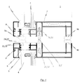
- FIG. 1 A known from the prior art support structure 1 for facades is in Fig. 1 shown.
- These support structures 1 usually consist of an outside metal profile 8, which is connected to avoid thermal bridges via insulating webs 6 with an inside metal profile 7.
- facade elements 4 are held by the profiles 7, 8 of the support structure 1. It is particularly common to connect the facade elements 4 via sealing elements 5 with the metal profiles 7, 8.
- Facade elements Provide 4 sealing strands to protect the facade from environmental influences.
- the sealing strands extend in the longitudinal direction of in Fig. 1 facade construction and sealing the façade in the vertical direction against the weather. For reasons of manageability, the sealing strands are not designed as a single strand, which extends along the entire extent of the facade.
- the sealing strands are formed as a plurality of individual partial strands 2, 2 ', which extend in the longitudinal direction of in Fig. 1 Facade structure 1 shown, between the facade elements 4, extend. So that the individual partial strands 2, 2 'of the sealing strands can be fastened adequately to the support structure 1, these have first, second and third anchoring regions 21, 21', 22, 22 ', 23, 23'.
- the anchoring regions 21, 21 ', 22, 22', 23, 23 'of the sealing strands are designed to engage in recesses of the profiles 7, 8 and, accordingly, to connect the sealing strands to the support structure 1.
- this seal-free intermediate space 3 is closed by a connecting element 100.
- This connecting element 100 spans the entire seal-free intermediate space 3 and has overlapping areas 101, 101 ', via which it is connected to the adjoining partial strands 2, 2' of the seal of the facade.
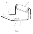
- FIGS. 2a and 2 B An embodiment of the connecting element 100 according to the invention is in the FIGS. 2a and 2 B shown.
- the connecting element 100 has a structure which is adapted to the structure of the partial strands 2, 2 'of the seal. That is, the connecting element 100 can be easily slipped over the partial strands 2 and 2 'of the seal and thus close the seal-free gap 3.
- the core 102 of the connector 100 is advantageously formed of a solid material.
- the material of the core 102 gives the connecting element 100 a stable structure which is sufficient to be able to absorb any stresses occurring within the support structure 1 or the partial strands 2, 2 'of the seal.
- the connecting element 100 On the upper side and the lower side of the connecting element 100 , further elastic regions 103, 104, 105 are provided, which are connected to the fixed core 102. This possibly airtight connection can be done for example by coextrusion, gluing or similar methods.
- the elastic regions 103, 104, 105 serve to connect the connecting element 100 as airtight as possible with the support structure 1.
- the solid core 102 may be made of hard PVC while the elastic region 103 is a coextruded layer of soft PVC.
- the fixed core 102 may also be somewhat elastic. It is advantageous here to form the fixed core 102 with a higher dimensional stability than is the case for the elastic regions 103, 104, 105, since the solid core 102 only has to adapt to the geometry of the support structure 1 to a small extent.
- the connecting element 100 is slipped over the known from the prior art sub-strands of the seal (only the first sub-strand 2 is shown).
- the elastic region 103 adapts to the bottom side of the connecting element 100 of the structure of the partial strands 2, 2 'and thus produces an air-tight and watertight connection.
- the elastic portions 103 are at least partially formed as anchoring areas 103a, 103b, 103c to allow a fixation of the connecting element 100 to the support structure 1 of the facade (see. Fig. 2 ).
- the anchoring areas 103a, 103b, 103c are inserted into the cavities of the support structure 1 in order to fasten the connecting element 100, thus guaranteeing the best possible insulating properties.
- the anchoring areas 103a, 103b, 103c also facilitate the insertion and the positioning of the connecting element 100 in the seal-free gap 3 of the facade.
- the anchoring areas 103a, 103b, 103c have a width which corresponds to the width of the seal-free intermediate space 3 at the sealing joints of the multipart sealing strands.
- the seal-free gap 3 is about 50 mm, which is why, by a corresponding adjustment of the anchoring areas 103a, 103b, 103c, as in Fig. 4 shown, the attachment of the connecting element 100 is further simplified. It is thus possible to attach the connecting element 100 according to the invention directly to the partial strands 2, 2 'of the seals, without first cutting the connecting element 100 to have to. For assembly of the connecting element 100, therefore, only a small part of the partial strands 2, 2 'in the overlapping region 101, 101' has to be cut off.
- the FIGS. 2 to 4 It can also be seen that the elastic regions 103, 104, 105 form at least one first sealing element 104.
- the first seal member 104 is configured to seal with a first seal string 9a of the support structure.
- the first sealing element 105 is preferably adapted to the shape of the first sealing strand 9a of the support structure.
- the elastic regions 103, 104, 105 form at least one second sealing element 105.
- the second sealing element 105 is advantageously designed to enter into a sealing connection with the inside profile 7 of the support structure 1.
- an airtight sealing connection between the connecting element 100 and the inside profile 7 of the support structure 1 can be achieved, which accordingly leads to the improvement of the thermal properties of the support structure 1 with the connecting element 100 according to the invention.
- the second sealing member 105 is used to securely fasten the connecting element of the invention to the support structure.
- the second sealing element 105 is preferably formed from a plurality of layers stacked on top of each other. These layers may be thin layers of soft PVC material. The layers are more advantageous Way formed such that the second sealing member 105 has a corrugated surface (see. Fig. 4 ), whereby the connecting element 100 according to the invention can be secured against slipping on the inside profile 7 of the support structure 1. In other words, the second sealing member 105 preferably forms a plurality of barbs formed by the edges of the individual layers.
Landscapes
- Engineering & Computer Science (AREA)
- Civil Engineering (AREA)
- Structural Engineering (AREA)
- Load-Bearing And Curtain Walls (AREA)
- Building Environments (AREA)
- Joining Of Corner Units Of Frames Or Wings (AREA)
Abstract
Description
- Die Erfindung betrifft ein Verbindungselement zum Schließen von Dichtungsstößen an Fassaden nach Patentanspruch 1. Insbesondere handelt es sich um ein Verbindungselement, welches zum Schließen der Dichtungen einen dichtungsfreien Zwischenraum überspannt und durch Überlappungsbereiche an den Enden der aneinanderstoßenden Dichtungen verbunden ist.
- Gebäudefassaden werden heutzutage zunehmend als Metall-Glas-Konstruktionen ausgebildet. Solche Fassaden weisen eine Trägerkonstruktion aus Metall als Grundgerüst auf, bei welchem einzelne flächige Fassadenelemente, wie Glasfenster oder auch Metall- bzw. Kunststoffelemente eingesetzt werden. Die Trägerkonstruktionen bestehen üblicherweise aus vertikal verlaufenden Pfostenelementen und horizontal verlaufenden Riegelelementen, welche die vertikal verlaufenden Pfostenelemente untereinander verbinden. Um Umwelteinflüsse am Durchdringen der Verbindung zwischen Trägerkonstruktion und Fassadenelementen zu hindern, werden Dichtungen an die Trägerkonstruktionen der Fassade angebracht.
- Aus Gründen einfacherer Handhabung und Montierbarkeit sind diese Dichtungen, welche sich entlang der Pfosten- bzw. Riegelelementen erstrecken, mehrteilig ausgeführt. Mit anderen Worten heißt das, dass es nicht üblich ist, die gesamte Fassade mit einem fortlaufenden Dichtungsstrang zu versehen. Folglich treten an den Endbereichen der jeweiligen Dichtungsprofile Stöße zwischen den Dichtungen auf. Diese Stöße bilden somit einen dichtungsfreien Zwischenraum aus, welcher sich nachteilig auf die Dämmeigenschaften der Fassade auswirken.
- Aus dem Stand der Technik ist es bekannt, obengenannte dichtungsfreie Zwischenräume unter Verwendung von Silikon oder ähnlichen Klebstoffen zu versiegeln. Bei dieser Lösung stellt sich allerdings das Problem der Dehnung bzw. Kontraktion der Trägerkonstruktion bzw. der Dichtungsprofile in Folge von Temperaturänderung. Die Dehnung bzw. Kontraktion in Folge von Temperaturänderungen kann an verschiedenen Stellen der Fassade unterschiedlich stark ausgeprägt sein, da der Temperatureinfluss nicht an allen Stellen der Fassade gleich groß ist. Solche Temperaturdifferenzen können beispielsweise durch unterschiedliche Bestrahlung an sonnigen Tagen (Schattenwurf durch andere Gebäude) entstehen. Ferner ist es denkbar, dass auch die Fassadenelemente aus unterschiedlichen Werkstoffen gebildet sind, wodurch sich - wie oben angedeutet - Verspannungen in der Fassadenkonstruktion ergeben können. Diese Verspannungen sind häufig ein Grund dafür, dass die geklebten Verbindungen in den dichtungsfreien Zwischenräumen beschädigt werden und somit ihre Dichtwirkung verlieren. Dessen ungeachtet ist es ferner nur sehr schwer möglich, unter Verwendung von Silikon oder Klebstoffen eine wasserdichte Versiegelung besagter Zwischenräume zu erreichen.
- Ausgehend von der oben genannten Problemstellung liegt der vorliegenden Erfindung die Aufgabe zugrunde, ein Verbindungselement zum Schließen von Dichtungsstößen an Fassaden anzugeben, welches eine ausreichende Stabilität aufweist, um Verspannungen in der Trägerkonstruktion bzw. den Dichtungsprofilen auszugleichen, und eine wind- und wasserdichte Verbindungsmöglichkeit zwischen den Dichtungsprofilen bereitstellt. Ferner ist es Aufgabe der Erfindung ein Verbindungselement anzugeben, welches günstig herstellbar ist und sich in einfacher Weise an gängigen Fassadenkonstruktionen anbringen lässt.
- Diese Aufgabe wird erfindungsgemäß durch ein Verbindungselement nach Patentanspruch 1 gelöst.
- Demnach handelt es sich bei der erfindungsgemäßen Lösung um ein Verbindungselement zum Schließen von Dichtungsstößen an Fassaden, wobei die Fassade Dichtungen aufweist, welche an Trägerkonstruktionen der Fassade, zwischen einzelnen Fassadenelementen angebracht sind. Dabei sind die Dichtungen, wie oben bereits erwähnt, mehrteilig als Teilstränge ausgeführt und bilden einen dichtungsfreien Zwischenraum an ihren Stößen aus. Das Verbindungselement zum Schließen des Dichtungsstoßes ist dazu ausgelegt den dichtungsfreien Zwischenraum zu überspannen und ist durch Überlappungsbereiche mit den Enden der stoßenden Teilstränge verbunden.
- Vorteilhafte Weiterbildungen der erfindungsgemäßen Lösung sind in den abhängigen Ansprüchen angegeben.
- So ist in einer vorteilhaften Realisierung des erfindungsgemäßen Verbindungselements zum Schließen von Dichtungsstößen vorgesehen, dass das Verbindungselement einen festen Kern so wie damit verbundene elastische Bereiche aufweist. Die Kombination aus einem festen Kern und den damit verbundenen elastischen Bereichen definiert ein Verbindungselement, welches stabil genug ist, um möglicherweise auftretende Verspannungen aufzunehmen und gleichzeitig, aufgrund der elastischen Bereiche, an das Fassadenprofil anpassbar ist, um größtmögliche Dämmeigenschaften zu erzielen. Ein solches Trägerelement hat darüber hinaus eine stabilisierende Wirkung auf die Fassadenkonstruktion, was sich beispielsweise als vorteilhaft bezüglich der auf die Fassade auftreffenden Windstöße herausstellt. Es ist dabei denkbar den festen Kern aus hartem PVC zu bilden, wobei die damit verbundenen elastischen Bereiche aus koextrudiertem weichem PVC bestehen. Selbstverständlich ist es auch denkbar, den die beiden Bereiche des Verbindungselements aus demselben Material auszubilden, um das Verbindungselement bspw. besser auf die Form der betreffenden Dichtungen/Trägerkonstruktionen anzupassen.
- Nach einer weiteren vorteilhaften Umsetzung des erfindungsgemäßen Verbindungselements sind die elastischen Bereiche zumindest teilweise als Verankerungsbereiche ausgebildet, um eine Fixierung des Verbindungselementes an der Trägerkonstruktion zu ermöglichen. Durch die Implementierung von Verankerungsbereichen am Verbindungselement, kann dieses sicher an der Trägerkonstruktion befestigt werden und garantiert damit bestmögliche Dämmeigenschaften. Selbstverständlich erleichtern diese Verankerungsbereiche außerdem das Einbringen und die Positionierung des Verbindungselementes im dichtungsfreien Zwischenraum der Fassade.
- Die Verankerungsbereiche weisen nach einer vorteilhaften Weiterbildung eine Breite auf, welche der Breite des Dichtungsfreien Zwischenraumes an den Dichtungsstößen der Teilstränge entspricht. Die Breite des dichtungsfreien Zwischenraumes beträgt typischerweise ca. 50 mm, weshalb durch eine entsprechende Anpassung der Verankerungsbereiche die Anbringung des Verbindungselements weiter vereinfacht wird. Es ist damit möglich, das erfindungsgemäße Verbindungselement direkt an die Teilstränge der Dichtungen anzubringen, ohne dieses vorher zuschneiden zu müssen.
- Gemäß einer weiteren Ausführungsform des erfindungsgemäßen Verbindungselements bilden die elastischen Bereiche zumindest ein erstes Dichtungselement aus, wobei das erste Dichtungselement dazu ausgelegt ist eine Dichtungsverbindung mit einem ersten Dichtungsstrang der Trägerkonstruktion einzugehen. Das erste Dichtungselement ist vorzugsweise auf die Form des ersten Dichtungsstrangs der Trägerkonstruktion angepasst. Folglich entsteht eine Dichtungsverbindung zwischen dem ersten Dichtungsstrang der Trägerkonstruktion und dem ersten Dichtungselements, welche das Eindringen von Wasser in den Innenraum der Trägerkonstruktion wirkungsvoll verhindert.
- Das erste Dichtungselement kann dabei, gemäß einem weiteren Aspekt der Erfindung, einen im Wesentlichen elliptischen Querschnitt aufweisen. Ein elliptischer Querschnitt gewährleistet eine verbesserte Verformbarkeit des ersten Dichtungselements, wodurch dieses auf eine Vielzahl von unterschiedlichen Dichtungssträngen anpassbar ist und eine lückenlose Dichtungsverbindung mit letzteren gewährleistet.
- Nach einer weiteren Realisierung bilden die elastischen Bereiche zumindest ein zweites Dichtungselement aus, wobei das zweite Dichtungselement dazu ausgelegt ist eine Dichtungsverbindung mit einem innenseitigen Profil der Trägerkonstruktion einzugehen. Wie mit Bezug auf die Figuren näher erläutert werden wird, weisen bekannte Trägerkonstruktionen innenseitige Profile auf, welche über sogenannte Isolierstege mit außenseitigen Profilen verbunden sind. Durch das zweite Dichtungselement kann eine luftdichte Dichtungsverbindung zwischen dem Verbindungselement und dem innenseitigen Profil der Trägerkonstruktion erreicht werden, was dementsprechend zur Verbesserung der thermischen Eigenschaften der Trägerkonstruktion mit dem erfindungsgemäßen Verbindungselement führt. Ebenfalls dient das zweite Dichtungselement dazu, das erfindungsgemäße Verbindungselement sicher an der Trägerkonstruktion zu befestigen.
- Das zweite Dichtungselement kann vorzugsweise aus mehreren Schichten besteht. Insbesondere kann es sich bei diesen Schichten um dünne Schichten aus weichem PVC-Material handeln. Die Schichten sind in vorteilhafter Weise derart ausgebildet, sodass das zweite Dichtungselement eine gewellte Oberfläche aufweist, wodurch das erfindungsgemäße Verbindungselement verrutschfest an dem innenseitigen Profil der Trägerkonstruktion befestigt werden kann. Mit anderen Worten bildet das zweite Dichtungselement vorzugsweise eine Vielzahl an Widerhaken aus, welche durch die Kanten der einzelnen Schichten ausgebildet werden.
- In den Zeichnungen ist ein Ausführungsbeispiel des erfindungsgemäßen Verbindungselementes dargestellt. Dabei zeigen:
-
Fig. 1 eine Schnittdarstellung einer aus dem Stand der Technik bekannten Trägerkonstruktion mit Dichtungsprofilen; -
Fig. 2a eine perspektivische Darstellung einer Ausführungsform des erfindungsgemäßen Verbindungselementes; -
Fig. 2b eine schematische Darstellung der Verbindung des erfindungsgemäßen Verbindungselements nachFig. 2a mit einer aus dem Stand der Technik bekannten Dichtung; -
Fig. 3 eine perspektivische Ansicht des erfindungsgemäßen Verbindungselements nachFig. 2a von unten; -
Fig. 4 eine Schnittdarstellung einer in die Trägerkonstruktion ausFig. 1 eingebauten Ausführungsform eines erfindungsgemäßen Verbindungselements; und -
Fig. 5 eine Frontansicht auf die inFig. 4 dargestellte Trägerkonstruktion mit erfindungsgemäßem Verbindungselement. - Im Folgenden sind gleiche oder gleich wirkende Bauteile aus Gründen der Übersichtlichkeit mit gleichen Bezugszeichen versehen.
- Eine aus dem Stand der Technik bekannte Trägerkonstruktion 1 für Fassaden ist in
Fig. 1 dargestellt. Diese Trägerkonstruktionen 1 bestehen für gewöhnlich aus einem außenseitigen Metallprofil 8, welches zur Vermeidung von Wärmebrücken über Isolierstege 6 mit einem innenseitigen Metallprofil 7 verbunden ist. Wie zu erkennen ist, werden Fassadenelemente 4 durch die Profile 7, 8 der Trägerkonstruktion 1 gehalten. Dabei ist es insbesondere üblich die Fassadenelemente 4 über Dichtungselemente 5 mit den Metallprofilen 7, 8 zu verbinden. Bei solchen aus dem Stand der Technik bekannten Trägerkonstruktionen 1 ist es ferner bekannt, zwischen den Fassadenelementen 4 Dichtungsstränge zum Schutz der Fassade vor Umwelteinflüssen vorzusehen. Die Dichtungsstränge erstrecken sich in Längsrichtung der inFig. 1 dargestellten Fassadenkonstruktion und Dichten die Fassade in vertikaler Richtung gegen Witterungseinflüsse ab. Aus Gründen der Handhabbarkeit sind die Dichtungsstränge nicht als einzelner Strang ausgeführt, welcher sich entlang der gesamten Ausdehnung der Fassade erstreckt. Vielmehr sind die Dichtungsstränge als mehrere einzelne Teilstränge 2, 2' ausgebildet, die sich in Längsrichtung der inFig. 1 dargestellten Fassadenkonstruktion 1, zwischen den Fassadenelementen 4, erstrecken. Damit die einzelnen Teilstränge 2, 2' der Dichtungsstränge angemessen an der Trägerkonstruktion 1 befestigt werden können, weisen diese erste, zweite und dritte Verankerungsbereiche 21, 21', 22, 22', 23, 23' auf. Die Verankerungsbereiche 21, 21', 22, 22', 23, 23' der Dichtungsstränge sind ausgebildet, in Ausnehmungen der Profile 7, 8 einzugreifen und dementsprechend die Dichtungsstränge mit der Trägerkonstruktion 1 zu verbinden. - Wie es in
Fig. 5 angedeutet ist, ergeben sich durch die Aufteilung der Dichtungsstränge in Teilstränge 2, 2' dichtungsfreie Zwischenräume 3, welche an den Dichtungsstößen der Teilstränge 2, 2' auftreten. - Erfindungsgemäß wird dieser dichtungsfreie Zwischenraum 3 von einem Verbindungselement 100 geschlossen. Dieses Verbindungselement 100 überspannt den gesamten dichtungsfreien Zwischenraum 3 und weist Überlappungsbereiche 101, 101' auf, über welche es mit den angrenzenden Teilsträngen 2,2' der Dichtung der Fassade verbunden ist.
- Eine Ausführungsform des erfindungsgemäßen Verbindungselements 100 ist in den
Figuren 2a und2b dargestellt. Das Verbindungselement 100 weist eine Struktur auf, welche an die Struktur der Teilstränge 2, 2' der Dichtung angepasst ist. Das heißt, das Verbindungselement 100 kann problemlos über die Teilstränge 2 bzw. 2' der Dichtung gestülpt werden und somit den dichtungsfreien Zwischenraum 3 schließen. - Der Kern 102 des Verbindungselements 100 ist in vorteilhafter Weise aus einem festen Material gebildet. Das Material des Kerns 102 verleiht dem Verbindungselement 100 eine stabile Struktur, welche ausreicht, um möglicherweise auftretende Verspannungen innerhalb der Trägerkonstruktion 1 bzw. den Teilsträngen 2, 2' der Dichtung aufnehmen zu können.
- Auf der Oberseite sowie der Unterseite des Verbindungselements 100 sind ferner elastische Bereiche 103, 104, 105 vorgesehen, welche mit dem festen Kern 102 verbunden sind. Diese möglichst luftdichte Verbindung kann beispielsweise durch Koextrusion, Kleben oder ähnliche Verfahren erfolgen. Die elastischen Bereiche 103, 104, 105 dienen dazu, das Verbindungselement 100 möglichst luftdicht mit der Trägerkonstruktion 1 zu verbinden. Beispielsweise kann der feste Kern 102 aus hartem PVC gefertigt sein, während der elastische Bereich 103 eine koextrudierte Schicht aus weichem PVC darstellt. Die Erfindung ist jedoch nicht hierauf beschränkt, vielmehr kann der feste Kern 102 auch in gewisser Weise elastisch sein. Es ist dabei von Vorteil den festen Kern 102 mit einer höheren Formstabilität auszubilden, als es für die elastischen Bereiche 103, 104, 105 der Fall ist, da sich der feste Kern 102 nur im geringen Maße an die Geometrie der Trägerkonstruktion 1 anpassen muss.
- Wie in
Fig. 2b dargestellt, wird das Verbindungselement 100 über die aus dem Stand der Technik bekannten Teilstränge der Dichtung (nur der erste Teilstrang 2 ist dargestellt) gestülpt. Dabei passt sich der elastische Bereich 103 auf der Bodenseite des Verbindungselements 100 der Struktur der Teilstränge 2, 2' an und stellt somit eine luft- und wasserdichte Verbindung her. - Wie in
Fig. 3 dargestellt, sind die elastischen Bereiche 103 zumindest teilweise als Verankerungsbereiche 103a, 103b, 103c ausgebildet, um eine Fixierung des Verbindungselements 100 an der Trägerkonstruktion 1 der Fassade zu ermöglichen (vgl.Fig. 2 ). Die Verankerungsbereiche 103a, 103b, 103c werden in die Hohlräume der Trägerkonstruktion 1 eingeschoben, um das Verbindungselement 100 zu befestigt, und garantieren damit bestmögliche Dämmeigenschaften. Selbstverständlich erleichtern die Verankerungsbereiche 103a, 103b, 103c außerdem das Einbringen und die Positionierung des Verbindungselementes 100 im dichtungsfreien Zwischenraum 3 der Fassade. - Von Vorteil ist es weiterhin, dass die Verankerungsbereiche 103a, 103b, 103c eine Breite aufweisen, welche der Breite des dichtungsfreien Zwischenraumes 3 an den Dichtungsstößen der mehrteiligen Dichtungsstränge entspricht. Typischerweise beträgt der dichtungsfreie Zwischenraum 3 ca. 50 mm, weshalb durch eine entsprechende Anpassung der Verankerungsbereiche 103a, 103b, 103c, wie in
Fig. 4 gezeigt, die Anbringung des Verbindungselements 100 weiter vereinfacht wird. Es ist damit möglich, das erfindungsgemäße Verbindungselement 100 direkt an den Teilsträngen 2, 2' der Dichtungen anzubringen, ohne das Verbindungselement 100 vorher zuschneiden zu müssen. Zur Montage des Verbindungselements 100 muss also lediglich ein kleiner Teil der Teilstränge 2, 2' im Überlappungsbereich 101, 101' abgetrennt werden. - Den
Figuren 2 bis 4 kann ferner entnommen werden, dass die elastischen Bereiche 103, 104, 105 zumindest ein erstes Dichtungselement 104 ausbilden. Das erste Dichtungselement 104 ist ausgelegt, eine Dichtungsverbindung mit einem ersten Dichtungsstrang 9a der Trägerkonstruktion einzugehen. Das erste Dichtungselement 105 ist vorzugsweise auf die Form des ersten Dichtungsstrangs 9a der Trägerkonstruktion angepasst. Insbesondere ist es vorteilhaft, das erste Dichtungselement 104 mit einem im Wesentlichen elliptischen Querschnitt auszugestalten. Folglich entsteht eine Dichtungsverbindung zwischen dem ersten Dichtungsstrang 9a der Trägerkonstruktion und dem ersten Dichtungselements 104, welche das Eindringen von Wasser in den Innenraum der Trägerkonstruktion 1 wirkungsvoll verhindert. - Bei genaurer Betrachtung der
Figur 2b ist ersichtlich, dass zur Montage des erfindungsgemäßen Verbindungselements 100 ein Teil des ersten Dichtungsstrangs 24 des ersten Teilstrangs 2 der Dichtung entfernt werden muss. Insbesondere handelt es sich dabei um denjenigen Teil des Dichtungsstranges 24, welcher sich im Überlappungsbereich 101 des Verbindungselements 100 mit dem Teilstrang 2 befindet. Der fehlende Teil des Dichtungsstrangs 24 wird erfindungsgemäß vom ersten Dichtungselement 104 des Verbindungselements 100 ersetzt. - Von Vorteil ist es auch, wenn die elastischen Bereiche 103, 104, 105 zumindest ein zweites Dichtungselement 105 ausbilden. Das zweite Dichtungselement 105 ist in vorteilhafter Weise dazu ausgelegt, eine Dichtungsverbindung mit dem innenseitigen Profil 7 der Trägerkonstruktion 1 einzugehen. Durch das zweite Dichtungselement 105 kann eine luftdichte Dichtungsverbindung zwischen dem Verbindungselement 100 und dem innenseitigen Profil 7 der Trägerkonstruktion 1 erreicht werden, was dementsprechend zur Verbesserung der thermischen Eigenschaften der Trägerkonstruktion 1 mit dem erfindungsgemäßen Verbindungselement 100 führt. Wie es vor allem anhand
Fig. 4 deutlich wird, dient das zweite Dichtungselement 105 dazu, das erfindungsgemäße Verbindungselement sicher an der Trägerkonstruktion zu befestigen. - Insbesondere ist das zweite Dichtungselement 105 dazu vorzugsweise aus mehreren aufeinander gestapelten Schichten gebildet. Es kann sich bei diesen Schichten um dünne Schichten aus weichem PVC-Material handeln. Die Schichten sind in vorteilhafter Weise derart ausgebildet, dass das zweite Dichtungselement 105 eine gewellte Oberfläche (vgl.
Fig. 4 ) aufweist, wodurch das erfindungsgemäße Verbindungselement 100 verrutschfest an dem innenseitigen Profil 7 der Trägerkonstruktion 1 befestigt werden kann. Mit anderen Worten bildet das zweite Dichtungselement 105 vorzugsweise eine Vielzahl an Widerhaken aus, welche durch die Kanten der einzelnen Schichten ausgebildet werden. - Die Erfindung ist nicht auf das unter Bezugnahme auf die Zeichnung beschriebene Ausführungsbeispiel beschränkt, sondern ergibt sich aus einer Zusammenschau sämtlicher hierin offenbarter Merkmale.
-
- 1
- Trägerkonstruktion
- 2, 2'
- Teilstrang der Dichtung
- 3
- dichtungsfreier Zwischenraum
- 4
- Fassadenelement
- 5
- Dichtungselement
- 6
- Isoliersteg
- 7
- innenseitiges Profil
- 8
- außenseitiges Profil
- 9a, 9b, 9c
- Dichtungsstrang
- 21, 21'
- erster Verankerungsbereich des Teilstrangs
- 22, 22'
- zweiter Verankerungsbereich des Teilstrangs
- 23, 23'
- dritter Verankerungsbereich des Teilstrangs
- 24, 24'
- Dichtungsstrang
- 100
- Verbindungselement
- 101, 101'
- Überlappungsbereich
- 102
- fester Kern
- 103
- elastischer Bereich
- 103a
- erster Verankerungsbereich
- 103b
- zweiter Verankerungsbereich
- 103c
- dritter Verankerungsbereich
- 104
- erstes Dichtungselement
- 105
- zweites Dichtungselement
Claims (9)
- Verbindungselement (100) zum Schließen eines bei einer Fassade zwischen zwei einander angrenzenden Dichtungssträngen (2, 2') gebildeten dichtungsfreien Zwischenraumes (3), wobei das Verbindungselement (100) ausgebildet ist, den dichtungsfreien Zwischenraum (3) zu überspannen, und wobei das Verbindungselement (100) Überlappungsbereiche (101, 101') aufweist, welche mit den Enden der einander angrenzenden Dichtungssträngen (2, 2') verbindbar sind.
- Verbindungselement (100) nach Anspruch 1,
wobei das Verbindungselement (100) einen elastischen Kern (102) sowie damit verbundene elastische Bereiche (103, 104, 105) aufweist. - Verbindungselement (100) nach Anspruch 2,
wobei die elastischen Bereiche (103, 104, 105) zumindest teilweise als Verankerungsbereiche (103a, 103b, 103c) ausgebildet sind, um eine Fixierung des Verbindungselementes (100) an der Trägerkonstruktion (1) der Fassade zu ermöglichen. - Verbindungselement (100) nach Anspruch 3,
wobei die Verankerungsbereiche (103a, 103b, 103c) eine Breite aufweisen, welche der Breite des dichtungsfreien Zwischenraumes (3) an den Dichtungsstößen der Teilstränge (2, 2') entspricht. - Verbindungselement (100) nach einem der Ansprüche 2 bis 4,
wobei die elastischen Bereiche (103, 104, 105) zumindest ein erstes Dichtungselement (104) ausbilden, wobei das erste Dichtungselement (104) dazu ausgelegt ist eine Dichtungsverbindung mit einem ersten Dichtungsstrang (9a) der Trägerkonstruktion (1) einzugehen. - Verbindungselement (100) nach Anspruch 5,
wobei das erste Dichtungselement (104) einen im Wesentlichen elliptischen Querschnitt aufweist. - Verbindungselement (100) nach einem der Ansprüche 2 bis 6,
wobei die elastischen Bereiche (103, 104, 105) zumindest ein zweites Dichtungselement (105) ausbilden, wobei das zweite Dichtungselement (105) dazu ausgelegt ist eine Dichtungsverbindung mit einem innenseitigen Profil (7) der Trägerkonstruktion (1) einzugehen. - Verbindungselement (100) nach Anspruch 7,
wobei das zweite Dichtungselement (105) aus mehreren Schichten, vorzugsweise Schichten aus weichem PVC-Material, besteht. - Fassade eines Gebäudes, mit einer Trägerkonstruktion (1) und Fassadenelementen (4, 4'), wobei die Fassade Dichtungen im Zwischenraum der Fassadenelemente (4, 4') aufweist, welche als Teilstränge (2, 2') mehrteilig ausgeführt sind und durch ein Verbindungselement (100) nach einem der vorhergehenden Ansprüche verbunden sind.
Priority Applications (1)
| Application Number | Priority Date | Filing Date | Title |
|---|---|---|---|
| EP11170497.9A EP2397643B1 (de) | 2010-06-18 | 2011-06-20 | Verbindungselement zum Schließen eines Dichtungsstoßes an Fassaden |
Applications Claiming Priority (2)
| Application Number | Priority Date | Filing Date | Title |
|---|---|---|---|
| EP10166450 | 2010-06-18 | ||
| EP11170497.9A EP2397643B1 (de) | 2010-06-18 | 2011-06-20 | Verbindungselement zum Schließen eines Dichtungsstoßes an Fassaden |
Publications (3)
| Publication Number | Publication Date |
|---|---|
| EP2397643A2 true EP2397643A2 (de) | 2011-12-21 |
| EP2397643A3 EP2397643A3 (de) | 2014-02-26 |
| EP2397643B1 EP2397643B1 (de) | 2018-03-14 |
Family
ID=44786186
Family Applications (1)
| Application Number | Title | Priority Date | Filing Date |
|---|---|---|---|
| EP11170497.9A Active EP2397643B1 (de) | 2010-06-18 | 2011-06-20 | Verbindungselement zum Schließen eines Dichtungsstoßes an Fassaden |
Country Status (1)
| Country | Link |
|---|---|
| EP (1) | EP2397643B1 (de) |
Cited By (1)
| Publication number | Priority date | Publication date | Assignee | Title |
|---|---|---|---|---|
| EP2735689A3 (de) * | 2012-11-21 | 2014-09-03 | Alcoa Aluminium Deutschland, Inc. | Entwässerungseinrichtung für einen Verbindungsbereich eines Pfostenprofils und eines Riegelprofils sowie Pfosten-Riegel-Profilanordnung mit einer Entwässerungseinrichtung |
Families Citing this family (1)
| Publication number | Priority date | Publication date | Assignee | Title |
|---|---|---|---|---|
| KR102620774B1 (ko) * | 2023-06-07 | 2024-01-05 | 제이에스이엔지(주) | 모듈형 건축 내·외장재 유닛 |
Family Cites Families (4)
| Publication number | Priority date | Publication date | Assignee | Title |
|---|---|---|---|---|
| US4843791A (en) * | 1987-10-29 | 1989-07-04 | The Standard Products Company | Cap fitting for gasket system intersections |
| DE4407284A1 (de) * | 1994-03-04 | 1995-09-14 | Manfred Woschko | Dichtungsanordnung für Fassaden |
| DE102008061709A1 (de) * | 2008-12-12 | 2010-06-17 | Norsk Hydro Asa | Dichtungsprofil, Verbindungsvorrichtung und Dichtung |
| DE202009013261U1 (de) * | 2009-10-02 | 2011-02-10 | Raico Bautechnik Gmbh | Dichtungsanordnung |
-
2011
- 2011-06-20 EP EP11170497.9A patent/EP2397643B1/de active Active
Non-Patent Citations (1)
| Title |
|---|
| None |
Cited By (1)
| Publication number | Priority date | Publication date | Assignee | Title |
|---|---|---|---|---|
| EP2735689A3 (de) * | 2012-11-21 | 2014-09-03 | Alcoa Aluminium Deutschland, Inc. | Entwässerungseinrichtung für einen Verbindungsbereich eines Pfostenprofils und eines Riegelprofils sowie Pfosten-Riegel-Profilanordnung mit einer Entwässerungseinrichtung |
Also Published As
| Publication number | Publication date |
|---|---|
| EP2397643B1 (de) | 2018-03-14 |
| EP2397643A3 (de) | 2014-02-26 |
Similar Documents
| Publication | Publication Date | Title |
|---|---|---|
| AT392111B (de) | Rahmenkonstruktion in pfosten-riegel-bauweise, insbesondere fuer fassaden, daecher od. dgl. | |
| DE2724755A1 (de) | Sturz zur abstuetzung der aeusseren mauerschicht von mauerwerk ueber wandoeffnungen | |
| WO2017207252A1 (de) | Dichtungsschnur zum abdichten einer fuge zwischen bauelementen sowie verfahren zur herstellung eines solchen | |
| EP2397643B1 (de) | Verbindungselement zum Schließen eines Dichtungsstoßes an Fassaden | |
| EP4249719A1 (de) | Anschlussprofilleiste | |
| AT515861B1 (de) | Kombiniertes Dicht- und Dämmsystem | |
| DE4343964C2 (de) | Gebäudekonstruktion als Glasfassade oder Glasdach | |
| DE102004008011A1 (de) | Unterstand, insbesondere Terassendach | |
| EP2341209A1 (de) | Profilanordnung | |
| DE202020002455U1 (de) | Anputzleiste mit Dichtungsbahn | |
| AT8398U1 (de) | Zweiteiliges laibungsanschlussprofil | |
| EP0374891A1 (de) | Gebäudewand aus Glasbauelementen | |
| DE20102789U1 (de) | Türblatt, insbesondere für eine Hauseingangstür, o.ä. Schichtkörper mit ebenen Flächen | |
| AT517223B1 (de) | Fugenabdichtung zwischen Dämmelementen zur Gebäudedämmung | |
| DE2611451C2 (de) | Dämmplatte zum Isolieren von Außen- und Innenflächen | |
| DE102022131325B4 (de) | Anordnung von Schalungselementen | |
| DE102014112145A1 (de) | Verbundprofil für Türen, Fenster oder Fassadenelemente | |
| AT14227U1 (de) | Aufnahmevorrichtung für eine Behangeinrichtung | |
| EP3587701B1 (de) | Anputzleisten-anordnung zum abdichten einer fuge | |
| DE20208153U1 (de) | Rahmenkonstruktion | |
| DE202009016136U1 (de) | Gewächshaus | |
| DE29805511U1 (de) | Fugenband | |
| EP1548197A1 (de) | Anordnung und Verfahren zum Abdichten von Fugen an Bauwerken, insbesondere von Dehnfugen in einer Aussenfassade | |
| EP3276100A1 (de) | Abdichtsystem für ein wandungssystem | |
| EP3168403A1 (de) | Kombiniertes dicht- und dämmsystem |
Legal Events
| Date | Code | Title | Description |
|---|---|---|---|
| AK | Designated contracting states |
Kind code of ref document: A2 Designated state(s): AL AT BE BG CH CY CZ DE DK EE ES FI FR GB GR HR HU IE IS IT LI LT LU LV MC MK MT NL NO PL PT RO RS SE SI SK SM TR |
|
| AX | Request for extension of the european patent |
Extension state: BA ME |
|
| PUAI | Public reference made under article 153(3) epc to a published international application that has entered the european phase |
Free format text: ORIGINAL CODE: 0009012 |
|
| PUAL | Search report despatched |
Free format text: ORIGINAL CODE: 0009013 |
|
| AK | Designated contracting states |
Kind code of ref document: A3 Designated state(s): AL AT BE BG CH CY CZ DE DK EE ES FI FR GB GR HR HU IE IS IT LI LT LU LV MC MK MT NL NO PL PT RO RS SE SI SK SM TR |
|
| AX | Request for extension of the european patent |
Extension state: BA ME |
|
| RIC1 | Information provided on ipc code assigned before grant |
Ipc: E06B 7/23 20060101AFI20140122BHEP Ipc: E06B 7/16 20060101ALI20140122BHEP Ipc: E06B 7/14 20060101ALI20140122BHEP |
|
| 17P | Request for examination filed |
Effective date: 20140825 |
|
| RBV | Designated contracting states (corrected) |
Designated state(s): AL AT BE BG CH CY CZ DE DK EE ES FI FR GB GR HR HU IE IS IT LI LT LU LV MC MK MT NL NO PL PT RO RS SE SI SK SM TR |
|
| 17Q | First examination report despatched |
Effective date: 20150806 |
|
| RAP1 | Party data changed (applicant data changed or rights of an application transferred) |
Owner name: KAWNEER ALUMINIUM DEUTSCHLAND INC. |
|
| REG | Reference to a national code |
Ref country code: DE Ref legal event code: R079 Ref document number: 502011013886 Country of ref document: DE Free format text: PREVIOUS MAIN CLASS: E06B0007160000 Ipc: B29C0065560000 |
|
| GRAP | Despatch of communication of intention to grant a patent |
Free format text: ORIGINAL CODE: EPIDOSNIGR1 |
|
| RIC1 | Information provided on ipc code assigned before grant |
Ipc: E06B 7/23 20060101ALI20170905BHEP Ipc: B29C 65/56 20060101AFI20170905BHEP Ipc: E04F 13/08 20060101ALI20170905BHEP Ipc: E06B 7/16 20060101ALI20170905BHEP Ipc: B29C 65/58 20060101ALI20170905BHEP Ipc: E06B 7/14 20060101ALI20170905BHEP |
|
| INTG | Intention to grant announced |
Effective date: 20170928 |
|
| GRAS | Grant fee paid |
Free format text: ORIGINAL CODE: EPIDOSNIGR3 |
|
| GRAA | (expected) grant |
Free format text: ORIGINAL CODE: 0009210 |
|
| AK | Designated contracting states |
Kind code of ref document: B1 Designated state(s): AL AT BE BG CH CY CZ DE DK EE ES FI FR GB GR HR HU IE IS IT LI LT LU LV MC MK MT NL NO PL PT RO RS SE SI SK SM TR |
|
| REG | Reference to a national code |
Ref country code: GB Ref legal event code: FG4D Free format text: NOT ENGLISH |
|
| REG | Reference to a national code |
Ref country code: CH Ref legal event code: EP Ref country code: AT Ref legal event code: REF Ref document number: 978436 Country of ref document: AT Kind code of ref document: T Effective date: 20180315 |
|
| REG | Reference to a national code |
Ref country code: IE Ref legal event code: FG4D Free format text: LANGUAGE OF EP DOCUMENT: GERMAN |
|
| REG | Reference to a national code |
Ref country code: DE Ref legal event code: R096 Ref document number: 502011013886 Country of ref document: DE |
|
| REG | Reference to a national code |
Ref country code: FR Ref legal event code: PLFP Year of fee payment: 8 |
|
| REG | Reference to a national code |
Ref country code: NL Ref legal event code: MP Effective date: 20180314 |
|
| REG | Reference to a national code |
Ref country code: LT Ref legal event code: MG4D |
|
| PG25 | Lapsed in a contracting state [announced via postgrant information from national office to epo] |
Ref country code: ES Free format text: LAPSE BECAUSE OF FAILURE TO SUBMIT A TRANSLATION OF THE DESCRIPTION OR TO PAY THE FEE WITHIN THE PRESCRIBED TIME-LIMIT Effective date: 20180314 Ref country code: FI Free format text: LAPSE BECAUSE OF FAILURE TO SUBMIT A TRANSLATION OF THE DESCRIPTION OR TO PAY THE FEE WITHIN THE PRESCRIBED TIME-LIMIT Effective date: 20180314 Ref country code: NO Free format text: LAPSE BECAUSE OF FAILURE TO SUBMIT A TRANSLATION OF THE DESCRIPTION OR TO PAY THE FEE WITHIN THE PRESCRIBED TIME-LIMIT Effective date: 20180614 Ref country code: CY Free format text: LAPSE BECAUSE OF FAILURE TO SUBMIT A TRANSLATION OF THE DESCRIPTION OR TO PAY THE FEE WITHIN THE PRESCRIBED TIME-LIMIT Effective date: 20180314 Ref country code: HR Free format text: LAPSE BECAUSE OF FAILURE TO SUBMIT A TRANSLATION OF THE DESCRIPTION OR TO PAY THE FEE WITHIN THE PRESCRIBED TIME-LIMIT Effective date: 20180314 Ref country code: LT Free format text: LAPSE BECAUSE OF FAILURE TO SUBMIT A TRANSLATION OF THE DESCRIPTION OR TO PAY THE FEE WITHIN THE PRESCRIBED TIME-LIMIT Effective date: 20180314 |
|
| PG25 | Lapsed in a contracting state [announced via postgrant information from national office to epo] |
Ref country code: SE Free format text: LAPSE BECAUSE OF FAILURE TO SUBMIT A TRANSLATION OF THE DESCRIPTION OR TO PAY THE FEE WITHIN THE PRESCRIBED TIME-LIMIT Effective date: 20180314 Ref country code: LV Free format text: LAPSE BECAUSE OF FAILURE TO SUBMIT A TRANSLATION OF THE DESCRIPTION OR TO PAY THE FEE WITHIN THE PRESCRIBED TIME-LIMIT Effective date: 20180314 Ref country code: BG Free format text: LAPSE BECAUSE OF FAILURE TO SUBMIT A TRANSLATION OF THE DESCRIPTION OR TO PAY THE FEE WITHIN THE PRESCRIBED TIME-LIMIT Effective date: 20180614 Ref country code: RS Free format text: LAPSE BECAUSE OF FAILURE TO SUBMIT A TRANSLATION OF THE DESCRIPTION OR TO PAY THE FEE WITHIN THE PRESCRIBED TIME-LIMIT Effective date: 20180314 Ref country code: GR Free format text: LAPSE BECAUSE OF FAILURE TO SUBMIT A TRANSLATION OF THE DESCRIPTION OR TO PAY THE FEE WITHIN THE PRESCRIBED TIME-LIMIT Effective date: 20180615 |
|
| PG25 | Lapsed in a contracting state [announced via postgrant information from national office to epo] |
Ref country code: MT Free format text: LAPSE BECAUSE OF FAILURE TO SUBMIT A TRANSLATION OF THE DESCRIPTION OR TO PAY THE FEE WITHIN THE PRESCRIBED TIME-LIMIT Effective date: 20180314 |
|
| PG25 | Lapsed in a contracting state [announced via postgrant information from national office to epo] |
Ref country code: RO Free format text: LAPSE BECAUSE OF FAILURE TO SUBMIT A TRANSLATION OF THE DESCRIPTION OR TO PAY THE FEE WITHIN THE PRESCRIBED TIME-LIMIT Effective date: 20180314 Ref country code: IT Free format text: LAPSE BECAUSE OF FAILURE TO SUBMIT A TRANSLATION OF THE DESCRIPTION OR TO PAY THE FEE WITHIN THE PRESCRIBED TIME-LIMIT Effective date: 20180314 Ref country code: EE Free format text: LAPSE BECAUSE OF FAILURE TO SUBMIT A TRANSLATION OF THE DESCRIPTION OR TO PAY THE FEE WITHIN THE PRESCRIBED TIME-LIMIT Effective date: 20180314 Ref country code: NL Free format text: LAPSE BECAUSE OF FAILURE TO SUBMIT A TRANSLATION OF THE DESCRIPTION OR TO PAY THE FEE WITHIN THE PRESCRIBED TIME-LIMIT Effective date: 20180314 Ref country code: AL Free format text: LAPSE BECAUSE OF FAILURE TO SUBMIT A TRANSLATION OF THE DESCRIPTION OR TO PAY THE FEE WITHIN THE PRESCRIBED TIME-LIMIT Effective date: 20180314 Ref country code: PL Free format text: LAPSE BECAUSE OF FAILURE TO SUBMIT A TRANSLATION OF THE DESCRIPTION OR TO PAY THE FEE WITHIN THE PRESCRIBED TIME-LIMIT Effective date: 20180314 |
|
| PG25 | Lapsed in a contracting state [announced via postgrant information from national office to epo] |
Ref country code: SK Free format text: LAPSE BECAUSE OF FAILURE TO SUBMIT A TRANSLATION OF THE DESCRIPTION OR TO PAY THE FEE WITHIN THE PRESCRIBED TIME-LIMIT Effective date: 20180314 Ref country code: CZ Free format text: LAPSE BECAUSE OF FAILURE TO SUBMIT A TRANSLATION OF THE DESCRIPTION OR TO PAY THE FEE WITHIN THE PRESCRIBED TIME-LIMIT Effective date: 20180314 Ref country code: SM Free format text: LAPSE BECAUSE OF FAILURE TO SUBMIT A TRANSLATION OF THE DESCRIPTION OR TO PAY THE FEE WITHIN THE PRESCRIBED TIME-LIMIT Effective date: 20180314 |
|
| REG | Reference to a national code |
Ref country code: DE Ref legal event code: R097 Ref document number: 502011013886 Country of ref document: DE |
|
| PG25 | Lapsed in a contracting state [announced via postgrant information from national office to epo] |
Ref country code: PT Free format text: LAPSE BECAUSE OF FAILURE TO SUBMIT A TRANSLATION OF THE DESCRIPTION OR TO PAY THE FEE WITHIN THE PRESCRIBED TIME-LIMIT Effective date: 20180716 |
|
| PLBE | No opposition filed within time limit |
Free format text: ORIGINAL CODE: 0009261 |
|
| STAA | Information on the status of an ep patent application or granted ep patent |
Free format text: STATUS: NO OPPOSITION FILED WITHIN TIME LIMIT |
|
| PG25 | Lapsed in a contracting state [announced via postgrant information from national office to epo] |
Ref country code: DK Free format text: LAPSE BECAUSE OF FAILURE TO SUBMIT A TRANSLATION OF THE DESCRIPTION OR TO PAY THE FEE WITHIN THE PRESCRIBED TIME-LIMIT Effective date: 20180314 |
|
| REG | Reference to a national code |
Ref country code: CH Ref legal event code: PL |
|
| 26N | No opposition filed |
Effective date: 20181217 |
|
| PG25 | Lapsed in a contracting state [announced via postgrant information from national office to epo] |
Ref country code: SI Free format text: LAPSE BECAUSE OF FAILURE TO SUBMIT A TRANSLATION OF THE DESCRIPTION OR TO PAY THE FEE WITHIN THE PRESCRIBED TIME-LIMIT Effective date: 20180314 |
|
| REG | Reference to a national code |
Ref country code: BE Ref legal event code: MM Effective date: 20180630 |
|
| REG | Reference to a national code |
Ref country code: IE Ref legal event code: MM4A |
|
| PG25 | Lapsed in a contracting state [announced via postgrant information from national office to epo] |
Ref country code: MC Free format text: LAPSE BECAUSE OF FAILURE TO SUBMIT A TRANSLATION OF THE DESCRIPTION OR TO PAY THE FEE WITHIN THE PRESCRIBED TIME-LIMIT Effective date: 20180314 Ref country code: LU Free format text: LAPSE BECAUSE OF NON-PAYMENT OF DUE FEES Effective date: 20180620 |
|
| PG25 | Lapsed in a contracting state [announced via postgrant information from national office to epo] |
Ref country code: LI Free format text: LAPSE BECAUSE OF NON-PAYMENT OF DUE FEES Effective date: 20180630 Ref country code: CH Free format text: LAPSE BECAUSE OF NON-PAYMENT OF DUE FEES Effective date: 20180630 Ref country code: IE Free format text: LAPSE BECAUSE OF NON-PAYMENT OF DUE FEES Effective date: 20180620 |
|
| PG25 | Lapsed in a contracting state [announced via postgrant information from national office to epo] |
Ref country code: BE Free format text: LAPSE BECAUSE OF NON-PAYMENT OF DUE FEES Effective date: 20180630 |
|
| REG | Reference to a national code |
Ref country code: DE Ref legal event code: R082 Ref document number: 502011013886 Country of ref document: DE Representative=s name: MEISSNER BOLTE PATENTANWAELTE RECHTSANWAELTE P, DE |
|
| REG | Reference to a national code |
Ref country code: AT Ref legal event code: MM01 Ref document number: 978436 Country of ref document: AT Kind code of ref document: T Effective date: 20180620 |
|
| PG25 | Lapsed in a contracting state [announced via postgrant information from national office to epo] |
Ref country code: AT Free format text: LAPSE BECAUSE OF NON-PAYMENT OF DUE FEES Effective date: 20180620 |
|
| PG25 | Lapsed in a contracting state [announced via postgrant information from national office to epo] |
Ref country code: TR Free format text: LAPSE BECAUSE OF FAILURE TO SUBMIT A TRANSLATION OF THE DESCRIPTION OR TO PAY THE FEE WITHIN THE PRESCRIBED TIME-LIMIT Effective date: 20180314 |
|
| PG25 | Lapsed in a contracting state [announced via postgrant information from national office to epo] |
Ref country code: HU Free format text: LAPSE BECAUSE OF FAILURE TO SUBMIT A TRANSLATION OF THE DESCRIPTION OR TO PAY THE FEE WITHIN THE PRESCRIBED TIME-LIMIT; INVALID AB INITIO Effective date: 20110620 |
|
| PG25 | Lapsed in a contracting state [announced via postgrant information from national office to epo] |
Ref country code: MK Free format text: LAPSE BECAUSE OF NON-PAYMENT OF DUE FEES Effective date: 20180314 |
|
| PG25 | Lapsed in a contracting state [announced via postgrant information from national office to epo] |
Ref country code: IS Free format text: LAPSE BECAUSE OF FAILURE TO SUBMIT A TRANSLATION OF THE DESCRIPTION OR TO PAY THE FEE WITHIN THE PRESCRIBED TIME-LIMIT Effective date: 20180714 |
|
| P01 | Opt-out of the competence of the unified patent court (upc) registered |
Effective date: 20230517 |
|
| PGFP | Annual fee paid to national office [announced via postgrant information from national office to epo] |
Ref country code: DE Payment date: 20250520 Year of fee payment: 15 |
|
| PGFP | Annual fee paid to national office [announced via postgrant information from national office to epo] |
Ref country code: GB Payment date: 20250520 Year of fee payment: 15 |
|
| PGFP | Annual fee paid to national office [announced via postgrant information from national office to epo] |
Ref country code: FR Payment date: 20250520 Year of fee payment: 15 |