EP2397230A1 - Dispositif pour produire un film de particules et procédé de production de ce film - Google Patents
Dispositif pour produire un film de particules et procédé de production de ce film Download PDFInfo
- Publication number
- EP2397230A1 EP2397230A1 EP10741116A EP10741116A EP2397230A1 EP 2397230 A1 EP2397230 A1 EP 2397230A1 EP 10741116 A EP10741116 A EP 10741116A EP 10741116 A EP10741116 A EP 10741116A EP 2397230 A1 EP2397230 A1 EP 2397230A1
- Authority
- EP
- European Patent Office
- Prior art keywords
- substrate
- particle
- concentration
- capacitance
- particles
- Prior art date
- Legal status (The legal status is an assumption and is not a legal conclusion. Google has not performed a legal analysis and makes no representation as to the accuracy of the status listed.)
- Granted
Links
Images


Classifications
-
- B—PERFORMING OPERATIONS; TRANSPORTING
- B05—SPRAYING OR ATOMISING IN GENERAL; APPLYING FLUENT MATERIALS TO SURFACES, IN GENERAL
- B05C—APPARATUS FOR APPLYING FLUENT MATERIALS TO SURFACES, IN GENERAL
- B05C11/00—Component parts, details or accessories not specifically provided for in groups B05C1/00 - B05C9/00
-
- B—PERFORMING OPERATIONS; TRANSPORTING
- B05—SPRAYING OR ATOMISING IN GENERAL; APPLYING FLUENT MATERIALS TO SURFACES, IN GENERAL
- B05D—PROCESSES FOR APPLYING FLUENT MATERIALS TO SURFACES, IN GENERAL
- B05D1/00—Processes for applying liquids or other fluent materials
-
- B—PERFORMING OPERATIONS; TRANSPORTING
- B05—SPRAYING OR ATOMISING IN GENERAL; APPLYING FLUENT MATERIALS TO SURFACES, IN GENERAL
- B05C—APPARATUS FOR APPLYING FLUENT MATERIALS TO SURFACES, IN GENERAL
- B05C3/00—Apparatus in which the work is brought into contact with a bulk quantity of liquid or other fluent material
- B05C3/18—Apparatus in which the work is brought into contact with a bulk quantity of liquid or other fluent material only one side of the work coming into contact with the liquid or other fluent material
-
- B—PERFORMING OPERATIONS; TRANSPORTING
- B05—SPRAYING OR ATOMISING IN GENERAL; APPLYING FLUENT MATERIALS TO SURFACES, IN GENERAL
- B05C—APPARATUS FOR APPLYING FLUENT MATERIALS TO SURFACES, IN GENERAL
- B05C9/00—Apparatus or plant for applying liquid or other fluent material to surfaces by means not covered by any preceding group, or in which the means of applying the liquid or other fluent material is not important
- B05C9/08—Apparatus or plant for applying liquid or other fluent material to surfaces by means not covered by any preceding group, or in which the means of applying the liquid or other fluent material is not important for applying liquid or other fluent material and performing an auxiliary operation
- B05C9/12—Apparatus or plant for applying liquid or other fluent material to surfaces by means not covered by any preceding group, or in which the means of applying the liquid or other fluent material is not important for applying liquid or other fluent material and performing an auxiliary operation the auxiliary operation being performed after the application
-
- B—PERFORMING OPERATIONS; TRANSPORTING
- B05—SPRAYING OR ATOMISING IN GENERAL; APPLYING FLUENT MATERIALS TO SURFACES, IN GENERAL
- B05D—PROCESSES FOR APPLYING FLUENT MATERIALS TO SURFACES, IN GENERAL
- B05D3/00—Pretreatment of surfaces to which liquids or other fluent materials are to be applied; After-treatment of applied coatings, e.g. intermediate treating of an applied coating preparatory to subsequent applications of liquids or other fluent materials
-
- B—PERFORMING OPERATIONS; TRANSPORTING
- B05—SPRAYING OR ATOMISING IN GENERAL; APPLYING FLUENT MATERIALS TO SURFACES, IN GENERAL
- B05D—PROCESSES FOR APPLYING FLUENT MATERIALS TO SURFACES, IN GENERAL
- B05D7/00—Processes, other than flocking, specially adapted for applying liquids or other fluent materials to particular surfaces or for applying particular liquids or other fluent materials
- B05D7/24—Processes, other than flocking, specially adapted for applying liquids or other fluent materials to particular surfaces or for applying particular liquids or other fluent materials for applying particular liquids or other fluent materials
-
- B—PERFORMING OPERATIONS; TRANSPORTING
- B05—SPRAYING OR ATOMISING IN GENERAL; APPLYING FLUENT MATERIALS TO SURFACES, IN GENERAL
- B05D—PROCESSES FOR APPLYING FLUENT MATERIALS TO SURFACES, IN GENERAL
- B05D2252/00—Sheets
- B05D2252/04—Sheets of definite length in a continuous process
-
- B—PERFORMING OPERATIONS; TRANSPORTING
- B05—SPRAYING OR ATOMISING IN GENERAL; APPLYING FLUENT MATERIALS TO SURFACES, IN GENERAL
- B05D—PROCESSES FOR APPLYING FLUENT MATERIALS TO SURFACES, IN GENERAL
- B05D2401/00—Form of the coating product, e.g. solution, water dispersion, powders or the like
- B05D2401/30—Form of the coating product, e.g. solution, water dispersion, powders or the like the coating being applied in other forms than involving eliminable solvent, diluent or dispersant
- B05D2401/32—Form of the coating product, e.g. solution, water dispersion, powders or the like the coating being applied in other forms than involving eliminable solvent, diluent or dispersant applied as powders
Definitions
- the present invention relates to a method for producing a particle film and an apparatus for producing a particle film, which apparatus can be suitably used for such a method for producing a particle film.
- an advective accumulation method has been known as a method for accumulating fine particles two-dimensionally or three-dimensionally at a high density on a substrate.
- the advective accumulation method is a method for dipping, in a dispersion liquid of particles dispersed for a long period of time in a solvent such as an aqueous solution, a flat substrate, such as glass, which has a strong affinity for the solvent and thereby producing a particle film on the substrate.
- This method achieves high-density accumulation of the particles through utilization of autonomous accumulating force of the particles at the interface between the substrate and the dispersion liquid.
- a dip coater has been mainly used so far for the formation a particle film by the advective accumulation method (e.g., see Non-patent Literature 1).
- a fine-particle film is formed on a substrate by, after dipping the substrate in a fine-particle dispersion liquid, withdrawing the substrate from the fine-particle dispersion liquid at a given speed.
- a meniscus between the substrate and the fine-particle dispersion liquid, whereby the nanoparticles are supplied toward the edge of the meniscus by a liquid current and capillary force.
- the solvent evaporates in the meniscus area, a decrease in thickness of the liquid film in relation to the film thickness of the particle film causes liquefaction bridging force between the particles, whereby the nanoparticles are immobilized on a surface of the substrate.
- Non-patent Literatures 2 and 3 there have been reports on a method for producing a particle film by a polystyrene particle dispersion liquid with use of a horizontally-driven nanocoater (e.g., see Non-patent Literatures 2 and 3). Specifically, there is disclosed a method for forming a particle film by inclining a second substrate at 0.14° to a first substrate, interposing therebetween a suspension containing nanoparticles, and moving only the first substrate in a horizontal direction.
- Non-patent Literature 1 has difficulty in forming a particle film on a substrate of a practical size with a high degree of accuracy.
- the method has difficulty in forming a particle film uniformly on a substrate of a practical size, because the density in the same plane of the particle film to be formed becomes nonuniform due to disturbances such as changes in temperature and humidity in working conditions.
- Non-patent Literatures 2 and 3 can form a particle film even on a substrate of a practical size, it is necessary to form a particle film more uniformly.
- the present invention has been made in view of the foregoing problems, and it is an object of the present invention to provide a method for producing a particle film and an apparatus for producing a particle film, which method and apparatus can form a particle film uniformly even on a substrate of a practical size.
- the inventors of the present invention diligently studied a method for forming a particle film uniformly even on a substrate of a practical size.
- the inventors found that a particle film can be formed uniformly on a substrate of a practical size by suppressing changes in concentration of particles in the meniscus area.
- the inventors accomplished the present invention.
- an apparatus for producing a particle film is an apparatus for producing a particle film by sweeping a meniscus area in a particle dispersion liquid filling a space between a first substrate and a second substrate facing the first substrate and by forming the particle film on the first substrate while evaporating a solvent in the meniscus area, the apparatus including: particle concentration measuring means for measuring a concentration of particles in the meniscus area; and particle concentration adjusting means for adjusting the concentration of particles in the meniscus area in accordance with the particle concentration measured by the particle concentration measuring means.
- the particle concentration adjusting means adjusts the concentration of particles in the meniscus area in accordance with the particle concentration measured by the particle concentration measuring means, it is possible to form a film while adjusting the concentration of particles in the meniscus area so that the concentration of particles in the meniscus area takes on a constant value. This brings about an effect of making it possible to form a particle film uniformly even on a substrate of a practical size.
- a method for forming a particle film according to the present invention is a method for producing a particle film by sweeping a meniscus area in a particle dispersion liquid filling a space between a first substrate and a second substrate facing the first substrate and by forming the particle film on the first substrate while evaporating a solvent in the meniscus area, the method including the steps of: (a) measuring a concentration of particles in the meniscus area; and (b) adjusting the concentration of particles in the meniscus area in accordance with the particle concentration measured in step (a).
- step (b) adjusts the concentration of particles in the meniscus area in accordance with the particle concentration measured by in step (a), it is possible to form a film while adjusting the concentration of particles in the meniscus area so that the concentration of particles in the meniscus area takes on a constant value. This brings about an effect of making it possible to form a particle film uniformly even on a substrate of a practical size.
- a particle film according to the present invention is produced by the method for producing a particle film according to the present invention, the particle film having an accumulation density controlled uniformly in a whole area of the particle film formed.
- the foregoing configuration makes it possible to provide a particle film having an accumulation density controlled uniformly in a whole area of the particle film formed.
- An apparatus for producing a particle film according to the present invention brings about an effect of making it possible to form a particle film uniformly even on a substrate of a practical size.
- a method for producing a particle film according to the present invention brings about an effect of making it possible to form a particle film uniformly even on a substrate of a practical size.
- a method for measuring a particle concentration according to the present embodiment included in a method for forming a particle film on a substrate by, while changing the position of a substrate in relation to a particle dispersion liquid with the substrate in contact with the particle dispersion liquid, evaporating the solvent in a meniscus area in the particle dispersion liquid with the meniscus area appearing on the substrate, is a method for measuring a concentration of particles in the meniscus area.
- the method for measuring a particle concentration includes (i) measuring capacitance in an area including the meniscus area and (ii) determining a particle concentration in accordance with the capacitance.
- the method for forming a particle film on a substrate, to which the method for measuring a particle concentration according to the present embodiment can be applied is an advective accumulation method and, specifically, the method for measuring a particle concentration according to the present embodiment can be applied to a method using a dip coater or a method for forming a film by filling a space between two such substrates as those described later with a particle dispersion liquid and moving either of the substrates.
- the capacitance of the particle dispersion liquid can be measured by measuring the capacitance formed between a sensor probe (hereinafter sometimes abbreviated simply as "probe") and the substrate, for example, in a case where the substrate has electrical conductivity.
- the capacitance of the particle dispersion liquid can be measured by grounding the first substrate, placing a probe of a capacitance meter so that the probe faces that surface of the first substrate on which a meniscus has appeared, and measuring capacitance between the probe and the first substrate.
- the capacitance of the particle dispersion liquid can be measured by using such a probe that capacitance is formed within the probe.
- a KLA-Tencor's proprietary probe (marketed as "2810") or the like, active utilization of broadening of an electric field allows measurement of capacitance between the probe and the substrate.
- the same level of sensitivity can be obtained as in the case where the substrate has electrical conductivity.
- An object whose capacitance is to be measured is not particularly limited, provided that it is an area in the meniscus that includes the particle dispersion liquid. It is possible to measure only capacitance in the meniscus area (which is an area composed of the particle dispersion liquid and an air layer between the dispersion liquid and the probe). Alternatively, it is possible to measure capacitance in a combination of the meniscus area and an area composed of the particle dispersion liquid, the second substrate, and an air layer between the second substrate and the probe.
- the probe be placed in such a position as to cover almost all of the meniscus area. In so doing, it is preferable that the probe be in such a position not to overlap the nanoparticle single layer film area that has been formed. If these conditions are met, part of the probe may overlap the second substrate in the case of formation of a film with use of the after-mentioned two substrates.
- changes in nanoparticle concentration can be satisfactorily measured in any position in which the probe has been placed, provided that the distance between the tip of the probe and the substrate is 1.5 mm or shorter.
- the probe be placed in close proximity to the substrate.
- the distance between the probe and the substrate be set within a range of not less than 200 ⁇ m to not greater than 3,000 ⁇ m or, more preferably, within a range of not less than 200 ⁇ m to not greater than 1.0 mm.
- the distance between the probe and the substrate be set within a range of not less than 200 ⁇ m to not greater than 3.0 mm, because detection is possible even in a position distant from the substrate. Setting the distance within the range allows suppression of inhibition of formation of a film directly under the probe and satisfactory measurement of the capacitance.
- the probe is in diameter, the better the probe can measure a local area.
- a decrease in diameter of the probe may lead to formation of unexpected capacitance between the probe and the second substrate.
- the probe used have a diameter of approximately 10 mm.
- the particle concentration and the capacitance are proportional to each other. Therefore, if a relational expression between the particle concentration and the capacitance is set up in advance by calculation or the like, the particle concentration can be measured by measuring the capacitance.
- the particle concentration and the capacitance are inversely proportional to each other. Therefore, similarly, if a relational expression between the particle concentration and the capacitance is set up in advance by calculation or the like, the particle concentration can be measured by measuring the capacitance.
- the method according to the present embodiment include determining the particle concentration in accordance with a degree of bending of the substrate in addition to the capacitance. This makes it possible to measure and adjust the particle concentration with a higher degree of accuracy.
- Such bending can be measured, for example, by placing a probe of a capacitance meter (e.g., of a capacitive displacement meter) separately so that the probe faces an surface of the first substrate opposite that surface of the first substrate on which a meniscus has appeared, measuring capacitance between the probe and the first substrate, and calculating bending of the first substrate from the capacitance.
- a capacitance meter e.g., of a capacitive displacement meter
- the nanoparticle concentration by (i) creating in advance a database of capacitance changes based solely on bending of the substrate in each position on the substrate by moving the substrate in the absence of a particle dispersion liquid and (ii) correcting measured capacitance values with use of the database so that capacitance changes based solely on bending of the substrate are cut to zero.
- This method is more preferable because it does not require provision of a separate capacitance meter.
- the foregoing has described the method for measuring a particle concentration according to the present embodiment, included in a method for forming a particle film on a substrate by, while changing the position of a substrate in relation to a particle dispersion liquid with the substrate in contact with the particle dispersion liquid, evaporating the solvent in a meniscus area of the particle dispersion liquid with the meniscus area appearing on the substrate, which is a method for measuring a concentration of particles in the meniscus area.
- the method for measuring a particle concentration according to the present embodiment is not limited to such a method.
- the method for measuring a particle concentration according to the present embodiment may be simply used to measure a concentration of particles in a particle dispersion liquid. This brings about substantially the same effect as the present embodiment, provided that the capacitance of the particle dispersion liquid is measured and the particle concentration is determined in accordance with the capacitance.
- a method for producing a particle film according to the present embodiment is a method for forming a particle film on a first substrate by, while moving the first substrate in a direction parallel to a plane of the first substrate to change from one position to another in relation to a second substrate, evaporating a solvent in a meniscus area in a particle dispersion liquid, the second substrate being placed opposite above the first substrate, the particle dispersion liquid filling a space between the first substrate and the second substrate, the meniscus area extending along the direction in which the first substrate moves to change from one position to another.
- the method for producing a particle film according to the present embodiment is preferably a method for forming a monoparticle film.
- the method for producing a particle film includes the steps of: (a) measuring a concentration of particles in the meniscus area; and (b) adjusting the concentration of particles in the meniscus area in accordance with the particle concentration obtained in step (a).
- Step (a) is a step of measuring a concentration of particles in the meniscus area.
- step (a) can be executed by the method for calculating a particle concentration from capacitance, which have been described above in the "(I) Method for Measuring a Particle Concentration" section, the method for obtaining a particle concentration by utilizing light scattering, or the like.
- step (a) in a case where step (a) is executed by the method for calculating a particle concentration from capacitance, it can be executed by grounding the first substrate and placing a probe of a capacitance meter so that the probe faces that surface of the first substrate on which a meniscus has appeared, as in the "(I) Method for Measuring a Particle Concentration" section above.
- step (a) include measuring capacitance in an area in the meniscus that includes the particle dispersion liquid and determining a particle concentration from the capacitance.
- an object whose capacitance is to be measured is not particularly limited, provided that it is an area in the meniscus that includes the particle dispersion liquid. It is possible to measure only capacitance in the meniscus area (which is, in reality, capacitance in an area composed of the particle dispersion liquid and an air layer between the dispersion liquid and the probe). Alternatively, it is possible to measure capacitance in a combination of the meniscus area and an area composed of the particle dispersion liquid, the second substrate, and an air layer between the second substrate and the probe.
- the distance between the probe and the first substrate be similarly set within a range of not less than 200 ⁇ m to not greater than 3,000 ⁇ m or, more preferably, within a range of not less than 200 ⁇ m to not greater than 1.0 mm.
- Step (b) is a step of adjusting the concentration of particles in the meniscus area in accordance with the particle concentration obtained in step (a).
- step (b) specifically, if the particle concentration obtained in step (a) is lower than a set particle concentration, the concentration in the meniscus area is adjusted to be higher, and if the particle concentration obtained in step (a) is higher than the set particle concentration, the concentration in the meniscus area is adjusted to be lower.
- Examples of the method for adjusting a particle concentration include (i) a method for applying an electric field between the first substrate and the second substrate, (ii) a method for adding a high-concentration particle dispersion liquid or a low-concentration particle dispersion liquid to the particle dispersion liquid, (iii) a method for changing the speed (displacement speed) at which the first substrate moves, etc.
- the particles in the particle dispersion liquid can be electrophoresed toward the meniscus by applying an electric field in a direction toward the meniscus.
- the particles in the particle dispersion liquid can be electrophoresed away from the meniscus by applying an electric field in a direction away from the meniscus.
- the particle concentration may be controlled by either of these operations or by both of the operations.
- the concentration of the particle dispersion liquid can be increased by adding, to the particle dispersion liquid, a prepared particle dispersion liquid whose concentration is higher than the initial concentration of the particle dispersion liquid and, as a result, the concentration of particles in the meniscus area can be increased.
- the concentration of the particle dispersion liquid can be reduced by adding, to the particle dispersion liquid, a prepared particle dispersion liquid whose concentration is lower than the initial concentration of the particle dispersion liquid and, as a result, the concentration of particles in the meniscus area can be reduced.
- the particle concentration may be controlled by either of these operations or by both of the operations.
- the amount of particles that are discharged from the meniscus for film formation is reduced by slowing down the speed at which the first substrate moves and, as a result, the concentration of particles in the meniscus area can be made higher than the initial concentration.
- step (a) in a case where the particle concentration obtained in step (a) is higher than the set particle concentration, the amount of particles that are discharged from the meniscus for film formation is increased by increasing the speed at which the first substrate moves and, as a result, the concentration of particles in the meniscus area can be made lower than the initial concentration.
- the particle concentration may be controlled by either of these operations or by both of the operations.
- the foregoing description presupposes a configuration of the method (iii) in which only the first substrate is moved.
- the amount of particles that are discharged from the meniscus for film formation can be similarly adjusted, for example, by a configuration in which only the second substrate is moved or a configuration in which both the first and second substrates are moved. Therefore, these configurations bring about substantially the same effect as the foregoing configuration.
- the amount of an electric field to be applied in the method (i), the amount of a dispersion liquid to be added in the method (ii), and the speed at which the first substrate moves in the method (iii) can be calculated as needed from the difference between the set particle concentration and the particle concentration measured in step (a).
- step (a) is executed by calculating a particle concentration from capacitance
- the method for producing a particle film according to the present embodiment further include the step of (c) measuring a degree of bending of the first substrate.
- step (a) includes determining the particle concentration in accordance with a degree of bending of the substrate in addition to the capacitance. This makes it possible to measure and adjust the particle concentration with a higher degree of accuracy.
- Step (c) is not necessary in the absence of bending of the first substrate used. Normally, however, there occurs bending in such a thin plate-shaped object. Moreover, due to such bending, there occurs a change in range of measurement of capacitance (in amount of the air layer) in step (a), and such a change may lead to an error in the particle concentration to be measured. Therefore, by determining the particle concentration in accordance with a degree of bending of the substrate as measured in step (c), the particle concentration can be measured and adjusted with a higher degree of accuracy.
- Step (c) can be executed, for example, by placing a probe of a separate capacitance meter so that the probe faces an surface of the first substrate opposite that surface of the first substrate on which a meniscus has appeared, measuring capacitance between the probe and the first substrate, and calculating bending of the first substrate from the capacitance.
- Step (c) may be executed during production of a particle film or may be executed by measuring bending of the first substrate in advance before feeding the particle dispersion liquid. That is, it is also possible to obtain the nanoparticle concentration by (i) creating in advance a database of capacitance changes based solely on bending of the first substrate, on which the particle film is formed, in each position on the first substrate by moving the first substrate in the absence of a particle dispersion liquid prior to film formation and (ii) correcting capacitance values, measured during film formation, on a computer with use of the database so that capacitance changes based solely on bending of the substrate are cut to zero. This method is more preferable because it does not require separate placement of a probe of a capacitance meter.
- Step (c) may be executed during production of a particle film or may be executed by measuring bending of the first substrate in advance before feeding the particle dispersion liquid.
- the particle concentration can be measured and adjusted with a higher degree of accuracy by first creating, through the measurement, a database of bending of the first substrate in relation to positions on the first substrate and then, in step (a), correcting the position of the probe or the like of the capacitance meter in accordance with the database.
- the first substrate for use in the present embodiment is not particularly limited, provided that it is a substrate on a surface of which a film of particles can be formed, but examples of the first substrate include a silicon substrate, a glass substrate, a metal substrate, a metal oxide substrate, a metal nitride substrate, a polymer substrate, an organic crystal substrate, a substrate made of a flat and smooth mineral such as mica, etc.
- the first substrate may be a substrate whose surface is coated with a binder layer.
- the binder layer may vary appropriately depending on the type of particles from which a film is formed, etc., but in a case where the particles used are Au particles, examples of the binder layer include: a thin-film layer of a polymer, such as modified polyethylene imine, polyvinyl pyrrolidone, or polyvinyl pyridine, which has an amino group; an amine self-assembled monolayer; and a layer of a hydrocarbon polymer, such as polystyrene, activated by atmospheric plasma containing minutely small amounts of oxygen, nitrogen, and water vapor and being composed mainly of a noble gas such as He or Ar.
- the first substrate and the second substrate need to have conductive surfaces.
- the first substrate include an ITO (indium tin oxide) substrate, an FTO (fluoride-tin-oxide) substrate, a ZnO 2 (zinc oxides) substrate, a silicon substrate, a metal substrate, and a conductive polymer substrate.
- the second substrate examples include, but are not limited to, a silicon substrate, a glass substrate, a metal substrate, a metal oxide substrate, a metal nitride substrate, a polymer substrate, an organic crystal substrate, a substrate made of a flat and smooth mineral such mica, etc.
- the second substrate also needs to have a conductive surface.
- examples of the second substrate include an ITO (indium tin oxide) substrate, an FTO (fluoride-tin-oxide) substrate, a ZnO 2 (zinc oxides) substrate, a silicon substrate, a metal substrate, and a conductive polymer substrate.
- the distance between the first substrate and the second substrate in the meniscus area may vary appropriately depending on the diameter of each of the particles from which a film is made, etc. and is not particularly limited, provided that it is 200 ⁇ m or shorter.
- the distance can be set within a range of 10 ⁇ m to 200 ⁇ m.
- the second substrate may be parallel or at an angle to the first substrate. However, it is preferable the second substrate be placed at an angle to the first substrate so that the distance between the first substrate and the second substrate on a side toward which the first substrate moves to change from one position to another is shorter than the distance between the first substrate and the second substrate on a side opposite to the side.
- the angle of the second substrate to the plane of the first substrate can be set, for example, within a range of 0.1 to 0.5°.
- the particle dispersion liquid is a dispersion liquid obtained by dispersing, in a solvent, particles from which a film is formed.
- the particles are not particularly limited, provided that a film can be formed from them on the first substrate, but examples of the particles include fine particles of such a polymer as typified by polystyrene or polyacrylic acid, fine particles of such a metal oxide as typified by silica or titanium oxide, fine particles of such a compound semiconductor as typified cadmium tellurium or cadmium selenium, fine particles of such a metal such as typified by gold, silver, or copper, fine particles of a biocompatible material such as titanium or hydroxyapatite, fine particle of carbon such as fullerene, etc.
- the particles be particles that become charged in the dispersion liquid.
- the method according to the present embodiment can, for example, use particles each having a diameter in a range of 3 to 2,000 nm.
- the solvent is not particularly limited, provided that it is a conductive solvent that allows the nanoparticles to be charged in the solution.
- the solvent include ultrapure water, an aqueous solution obtained by dissolving ion species of sodium, calcium, etc. in ultrapure water, an ionic liquid, an aqueous polymer solution, etc.
- the concentration of particles in the particle dispersion liquid can vary appropriately depending on the speed at which the substrate move and the coverage of the particle film to be produced.
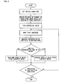
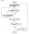
- Fig. 9 shows a flow chart of an example of the aforementioned method for producing a particle film. It should be noted that in this example of the production method includes measuring capacitance in an area in the meniscus that includes the particle dispersion liquid and determining a particle concentration from the capacitance.
- initial conditions such as the film-forming speed and the position on the substrate in which the film is formed are set first, and a database of capacitance changes based solely on bending of the first substrate in each position on the first substrate is created then (step (c)).
- the particle film is formed on the first substrate by filling a space between the first substrate and the second substrate with the particle dispersion liquid, forming a meniscus, and moving the first substrate while evaporating the solvent.
- the concentration of particles in the meniscus area is measured every predetermined period of time (step (a)).
- the particle concentration is measured by obtaining a nanoparticle concentration by correcting measured capacitance values on a computer, with use of the database of capacitance changes based solely on bending of the first substrate 1, so that capacitance changes based solely on bending of the first substrate 1 are cut to zero.
- the particle concentration is adjusted in accordance with the concentration thus obtained (step (b)). Specifically, if the particle concentration thus measured is higher than the set value, the speed at which the first substrate moves is increased, or if the particle concentration thus measured is lower than the set value, the speed at which the first substrate moves is slowed down. Moreover, by repeating this series of operations until completion of film formation, the particle film can be produced.
- the aforementioned database of capacitance changes based solely on bending of the first substrate is created, specifically, by first measuring capacitance changes based solely on bending of the first substrate in the absence of a particle dispersion liquid, outputting results of the measurement to a computer or the like together with position information of the first substrate, and then repeating these operations until the end of creation of the database while moving the first substrate.
- a method for suppressing an error due to bending of the first substrate is a method for correcting the position of the probe in the capacitance meter by piezoelectric control.
- the aforementioned method for obtaining a nanoparticle concentration by correcting, on a computer particle concentration values measured based on degrees of bending is more preferable.
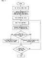
- the method for correcting the position of the probe in the capacitance meter by piezoelectric control is carried out in the following manner. Specifically, as shown in Fig. 11 , initial conditions such as the film-forming speed and the position on the substrate in which the film is formed are set first, and a database for correcting the position of the probe in the capacitance meter in accordance with slight differences, such as bending, in surface shape of the first substrate is created then.
- the particle film is formed on the first substrate by filling a space between the first substrate and the second substrate with the particle dispersion liquid, forming a meniscus, and moving the first substrate while evaporating the solvent.
- the concentration of particles in the meniscus area is measured every predetermined period of time by correcting the position of the probe in the capacitance meter in accordance with the database created in advance (step (a)). Then, as in the case of the aforementioned method, the particle concentration is adjusted in accordance with results of the measurement (step (b)).
- the database for correcting the position of the probe in the capacitance meter is created in the following manner. Specifically, as shown in Fig. 12 , capacitance is measured by a probe of a capacitance meter in the absence of a particle dispersion liquid, with the probe placed to face a surface of the first substrate, and the position of the probe in the capacitance meter in relation to the first substrate (specifically, the inclination of a measuring plane of the probe in the capacitance meter in relation to the plane of the first substrate) is calculated from the capacitance (step (c)).
- the position of the probe in the capacitance meter is corrected so that the inclination becomes not greater than 3.4 mrad, and this operation is repeated until the inclination of the measuring plane of the probe in the capacitance meter in relation to the plane of the first substrate becomes not greater than 3.4 mrad.
- changes in voltage value as changes in capacitance value are outputted to a computer or the like together with position information of the first substrate. Then, by carrying out these operations for each position on the first substrate in which the particle film is formed, a database of degrees of correction of the position of the probe in the capacitance meter in each position on the first substrate is created.
- the flow charts of Figs. 9 and 11 have shown, as examples of the method for adjusting a particle concentration, the method for changing the speed at which the first substrate moves.
- a threshold for the inclination of the measuring plane of the probe in the capacitance meter in relation to the plane of the first substrate has been set at 3.4 mrad, this value can vary appropriately for any purpose.
- the aforementioned method for producing a particle film according to the present embodiment can be more suitably implemented, for example, by a production apparatus described below.
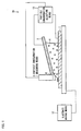
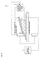
- Fig. 1 shows a cross-sectional view schematically showing an example of an apparatus for producing a particle film according to the present embodiment.
- Fig. 2 shows a perspective view schematically showing an example of arrangement of a first substrate 1 and a second substrate 2 in the apparatus for producing a particle film according to the present embodiment.
- the apparatus 20 for producing a particle film is an apparatus for forming a particle film on a first substrate 1 by, while moving the first substrate 1 in a direction parallel to a plane of the first substrate 1 to change from one position to another in relation to a second substrate 2, evaporating a solvent in a meniscus area 5 in a particle dispersion liquid 4, the second substrate 2 being placed opposite above the first substrate 1, the particle dispersion liquid 4 filling a space between the first substrate 1 and the second substrate 2, the meniscus area 5 extending along the direction in which the first substrate 1 moves to change from one position to another.
- the apparatus 20 for producing a particle film includes: substrate placing means 11 for placing the first substrate 1 and the second substrate 2 so that they face each other; substrate moving means 12 for changing the position of the first substrate 1 in relation to the position of the second substrate 2 along the direction parallel to the plane of the first substrate 1; particle concentration measuring means 3 for measuring a concentration of particles in the meniscus area 5; and particle concentration adjusting means 13 for adjusting the concentration of particles in the meniscus area 5 in accordance with the particle concentration measured by the particle concentration measuring means 3.
- the substrate placing means 11 is not particularly limited, provided that it is configured to place the first substrate 1 and the second substrate 2 so that they face each other.
- the substrate placing means 11 may be configured such that the second substrate 2 is fixed by a fixing device such as a clamp and the first substrate 1 is fixed to a board or the like, provided with a fixing device such as a clamp, which has a surface on which the first substrate 1 is mounted.
- a fixing device such as a clamp
- the first substrate 1 is allowed to change from one position to another along the direction parallel to the plane of the first substrate 1.
- the substrate moving means 12 is not particularly limited, provided that it can change the position of the first substrate 1 in relation to the position of the second substrate 2.
- the substrate moving means 12 is configured to move the first substrate 1 by a stepping motor, a servo-motor-controlled X stage, or the like.
- the substrate moving means 12 may be configured to move the second substrate 2 by a stepping motor or the like with the first substrate 1 fixed.
- the particle concentration measuring means 3 is not particularly limited, provided that it can measure a concentration of particles in the meniscus area 5.
- the particle concentration measuring means 3 is configured as a capacitance meter, which has been described above in the "(I) Method for Measuring a Particle Concentration" section, or a configuration for obtaining a particle concentration by utilizing light scattering or light reflection.
- the particle concentration measuring means can be configured to include: a capacitance meter; and particle concentration calculating means for calculating a particle concentration in accordance with capacitance measured by the capacitance meter.
- the particle concentration adjusting means 13 is configured, for example, to adjust the concentration of particles in the meniscus area 5 by applying an electric field between the first substrate 1 and the second substrate 2.
- a straight line connecting (a) an end 10 of the second substrate 2 that is in contact with the particle dispersion liquid 4 in the meniscus area 5 with (b) a portion of the first substrate 1 that is in contact with an end of the meniscus area 5 of the particle dispersion liquid 4 is not perpendicular to the direction parallel to the plane of the first substrate 1, but inclines from the second substrate 2 to the first substrate 1 as it extends closer to the meniscus area 5. For this reason, a line of electric force that is generated from the second substrate 2 to the first substrate 1 extends in a direction toward the meniscus area 5. Therefore, by applying an electric field from the first substrate 1 to the second substrate 2, particles can be moved toward the meniscus area 5.
- the particle concentration adjusting means 13 is configured to adjust the concentration of particles in the meniscus area 5 by applying an electric field between the first substrate 1 and the second substrate 2, this does not imply any limitation.
- the particle concentration adjusting means 13 may be configured, for example, to add a high-concentration particle dispersion liquid or a low-concentration particle dispersion liquid to the particle dispersion liquid. This brings about substantially the same effect as the present embodiment, provided that the particle concentration adjusting means 13 can adjust the concentration of particles in the meniscus area 5.
- An example of such a configuration is a configuration for adding a high-concentration particle dispersion liquid or a low-concentration particle dispersion liquid by a syringe pump, a tube head, or the like.
- the particle concentration adjusting means 13 may be configured to adjust the concentration of particles in the meniscus area 5 by changing the speed at which at least either the first substrate 1 or the second substrate moves, i.e., by controlling the sweep rate.
- the particle concentration adjusting means 13 is configured, as in the present embodiment, to adjust the concentration of particles in the meniscus area 5 by applying an electric field between the first substrate 1 and the second substrate 2, the particle concentration can be controlled more easily, which brings about an especially significant effect.
- the apparatus for producing a particle film according to the present embodiment further include bending-measuring means for measuring a degree of bending of the first substrate.
- Fig. 13 shows a cross-sectional view schematically showing an example of an apparatus for producing a particle film including bending-measuring means.
- the production apparatus 20' of Fig. 13 includes the bending-measuring means 6, the production apparatus 20' can measure and adjust a particle concentration with a higher degree of accuracy.
- the bending-measuring means 6 can calculate bending of the first substrate 1 from the capacitance. This allows the particle concentration measuring means 3, as a result, to determine the particle concentration in accordance with a degree of bending measured by the bending-measuring means 6, in addition to the capacitance.
- the measurement of a degree of bending of the first substrate 1 by the bending-measuring means 6 may be performed during production of a particle film or may be performed by measuring bending of the first substrate 1 in advance before feeding the particle dispersion liquid.
- the particle concentration can be measured and adjusted with a higher degree of accuracy by creating, through the measurement, a database of bending of the first substrate in relation to positions on the first substrate, correcting an error due to bending of the first substrate in accordance with the database, and calculating the particle concentration.
- the nanoparticle concentration by (i) creating in advance a database of capacitance changes based solely on bending of the first substrate, on which the particle film is formed, in each position on the first substrate by moving the first substrate in the absence of a particle dispersion liquid prior to film formation and (ii) correcting capacitance values, measured during film formation, on a computer with use of the database so that capacitance changes based solely on bending of the substrate are cut to zero.
- Fig. 14 is a block diagram schematically showing an example of an apparatus for producing a particle film according to such an embodiment.
- the method for correcting the particle concentration in accordance with a degree of bending is more preferable.
- a production apparatus 20" is configured such that initial condition setting means 7, substrate moving means 12, and particle concentration adjusting means 13 are controlled by a control computer 9.
- the apparatus 20" for producing a particle film includes, as the particle concentration adjusting means 13, substrate speed varying means 14, electric field applying means 15, and particle dispersion liquid feeding means 16, each of which is connected to the control computer 9.
- the production apparatus 20" includes the initial condition setting means 7 for setting initial conditions before the start of production of a particle film.
- the initial condition setting means 7 is means for setting initial conditions for film formation by inputting the film-forming speed, the position on the substrate in which the film is formed, etc.
- the initial condition setting means 7 includes capacitance probe position determining means 8 and uses the capacitance probe position determining means 8 to create a database for correcting the position of the probe of the capacitance meter in accordance with slight differences, such as bending, in shape of the substrate.
- a database for correcting the position of the probe of the capacitance meter in accordance with an error in shape of the first substrate 1 in each position on the first substrate is created. Creation of such a database allows the particle concentration measuring means 3 to correct the position of the probe of the capacitance meter in accordance with the database. This makes it possible to prevent an error of measurement of particle concentration from occurring due to a slight difference in shape of the first substrate 1.
- a method for producing a particle film according to the present embodiment is a method for forming a particle film on a first substrate by, while moving the first substrate in a direction parallel to a plane of the first substrate to change from one position to another in relation to a second substrate, evaporating a solvent in a meniscus area in a particle dispersion liquid, the second substrate being placed opposite above the first substrate, the particle dispersion liquid filling a space between the first substrate and the second substrate, the meniscus area extending along the direction in which the first substrate moves to change from one position to another, the method including the steps of: (a) measuring a concentration of particles in the meniscus area; and (b) adjusting the concentration of particles in the meniscus area in accordance with the particle concentration measured in step (a).
- step (b) adjusts the concentration of particles in the meniscus area in accordance with the particle concentration measured by in step (a), it is possible to form a film while adjusting the concentration of particles in the meniscus area so that the concentration of particles in the meniscus area takes on a constant value. This brings about an effect of making it possible to form a particle film uniformly even on a substrate of a practical size.
- the concentration of particles in the meniscus area can be adjusted so that the concentration of particles in the meniscus area takes on a constant value, the particle film can be formed uniformly in a shorter period of time. This makes it possible to produce a particle film with higher production efficiency.
- step (a) includes (i) measuring capacitance in an area including the meniscus area and (ii) determining a particle concentration from the capacitance.
- the particle concentration can be measured easily with a higher degree of accuracy in step (a). This brings about a further effect of making it possible to form a particle film easily and more uniformly.
- the method for producing a particle film according to the present invention is preferably configured to further include the step of (c) measuring a degree of bending of the first substrate, wherein step (a) includes determining the particle concentration in accordance with the degree of bending measured in step (c), in addition to the capacitance.
- the particle concentration is determined in accordance with the degree of bending in addition to the capacitance, the particle concentration can be measured with a higher degree of accuracy in step (a). Therefore, the particle concentration can be adjusted with a higher degree of accuracy in step (b). This brings about a further effect of making it possible to form a particle film more uniformly.
- step (b) includes adjusting the concentration of particles in the meniscus area by applying an electric field between the first substrate and the second substrate.
- the particle concentration can be adjusted more easily in step (b). This brings about a further effect of making it possible to form a particle film more easily.
- the method for producing a particle film according to the present invention is preferably configured such that the second substrate is placed at an angle to the first substrate so that the distance between the first substrate and the second substrate on a side toward which the first substrate moves to change from one position to another is shorter than the distance between the first substrate and the second substrate on a side opposite to the side.
- the second substrate is placed at an angle to the first substrate, a line of contact between the particle dispersion liquid in the meniscus area and the first substrate can be made more uniform. This brings about a further effect of making it possible to form a particle film more uniformly.
- an apparatus for producing a particle film is an apparatus for forming a particle film on a first substrate by, while moving the first substrate in a direction parallel to a plane of the first substrate to change from one position to another in relation to a second substrate, evaporating a solvent in a meniscus area in a particle dispersion liquid, the second substrate being placed opposite above the first substrate, the particle dispersion liquid filling a space between the first substrate and the second substrate, the meniscus area extending along the direction in which the first substrate moves to change from one position to another, the apparatus including: particle concentration measuring means for measuring a concentration of particles in the meniscus area; and particle concentration adjusting means for adjusting the concentration of particles in the meniscus area in accordance with the particle concentration measured be the particle concentration measuring means.
- the particle concentration adjusting means adjusts the concentration of particles in the meniscus area in accordance with the particle concentration measured by the particle concentration measuring means, it is possible to form a film while adjusting the concentration of particles in the meniscus area so that the concentration of particles in the meniscus area takes on a constant value. This brings about an effect of making it possible to form a particle film uniformly even on a substrate of a practical size.
- the apparatus for producing a particle film according to the present invention is preferably configured such that the particle concentration measuring means measures capacitance in an area including the meniscus area with use of a capacitance meter and determines a particle concentration from the capacitance.
- the particle concentration measuring means can measure the particle concentration easily with a higher degree of accuracy. This brings about a further effect of making it possible to form a particle film more easily and uniformly.
- the apparatus for producing a particle film according to the present invention is preferably configured to further include bending-measuring means for measuring a degree of bending of the first substrate, wherein the particle concentration measuring means determines the particle concentration in accordance with the degree of bending measured by the bending-measuring means, in addition to the capacitance.
- the particle concentration measuring means can measure the particle concentration with a higher degree of accuracy. Therefore, the particle concentration adjusting means can adjust the particle concentration with a higher degree of accuracy. This brings about a further effect of making it possible to form a particle film more uniformly.
- the apparatus for producing a particle film according to the present invention is preferably configured such that the particle concentration adjusting means adjusts the concentration of particles in the meniscus area by applying an electric field between the first substrate and the second substrate.
- the particle concentration adjusting means can adjust the particle concentration more easily. This brings about a further effect of making it possible to form a particle film more easily.
- the apparatus for producing a particle film according to the present invention is preferably configured such that the second substrate is placed at an angle to the first substrate so that the distance between the first substrate and the second substrate on a side toward which the first substrate moves to change from one position to another is shorter than the distance between the first substrate and the second substrate on a side opposite to the side.
- the second substrate is placed at an angle to the first substrate, a line of contact between the particle dispersion liquid in the meniscus area and the first substrate can be made more uniform. This brings about a further effect of making it possible to form a particle film more uniformly.
- the apparatus for producing a particle film according to the present invention is preferably configured such that the particle concentration adjusting means adjusts the concentration of particles in the meniscus area by changing a speed at which the first substrate changes from one position to another.
- the particle concentration adjusting means can control the particle concentration more easily. This brings about a further effect of making it possible to form a particle film more easily.
- a method for measuring a particle concentration according to the present invention includes the steps of: measuring capacitance in a particle dispersion liquid; and determining a particle concentration in accordance with the capacitance.
- the concentration of particles in the meniscus area can be obtained while forming the particle film, it becomes possible to adjust, in accordance with the particle concentration obtained as a result, the concentration of particles in the meniscus so that the concentration of particles in the meniscus takes on a constant value. This brings about an effect of making it possible to form a particle film uniformly even on a substrate of a practical size.
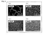
- Dispersion liquids were prepared by dispersing polystyrene particles each having a diameter of 260 nm (marketed as "Research Polystyrene Particles 5026A"; manufactured by MORITEX Corporation) in water in concentrations of 5% by volume, 10% by volume, 15% by volume, and 20% by volume, respectively.
- particle films each having a size of 30 ⁇ 60 mm 2 were formed on the first substrate while moving the first substrate at a film-forming speed of 100 ⁇ m/s.
- the first substrate was a silicon substrate coated with a binder layer.
- the silicon substrate coated with the binder layer was prepared as follows: A solution was prepared by dissolving polystyrene (marketed as "Polystyrene”; manufactured by Kishida Chemicals Co., Ltd.) in toluene, and a silicon substrate having a thickness of 0.7 mm was spin-coated with the solution so that the solution formed into a binder layer of polystyrene having a thickness of 200 nm or smaller. Further, the second substrate used was made of ITO glass. The first substrate and the second substrate were placed at a distance of 50 ⁇ m from each other, with the second substrate at an angle of 0.14° to the plane of the first substrate.
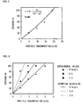
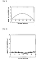
- the particle films thus obtained were observed with an SEM, and particle densities were calculated through image processing analysis based on the resulting images. These results are shown in Figs. 3 and 4 .
- the solid line shown in Fig. 4 is a curve derived from a theoretical expression based on a physical model, and the plot shows experimental results.
- the experimental results match well with the theoretical expression, and it was confirmed that under such conditions as a diameter of 260 nm and a film-forming speed of 100 ⁇ m, the resulting monolayer film is most densely filled with particles when the particle concentration is 20.0% by mass.
- Dispersion liquids were prepared by dispersing polystyrene particles each having a diameter of 1,000 nm (marketed as "Research Polystyrene Particles 5100A"; manufactured by MORITEX Corporation) in water in concentrations of 1.0% by volume, 2.0% by volume, 3.0% by volume, and 4.0% by volume, respectively.
- particle films each having a size of 30 ⁇ 60 mm 2 were formed on the first substrate while moving the first substrate at film-forming speeds of 3.0 ⁇ m/s, 6.0 ⁇ m/s, and 9.0 ⁇ m/s, respectively.
- the first substrate was a silicon substrate coated with a binder layer.
- the silicon substrate coated with the binder layer was prepared as follows: A solution was prepared by dissolving polystyrene (marketed as "Polystyrene”; manufactured by Kishida Chemicals Co., Ltd.) in toluene, and a silicon substrate having a thickness of 0.7 mm was spin-coated with the solution so that the solution formed into a binder layer of polystyrene having a thickness of 200 nm or smaller. Further, the second substrate used was made of ITO glass. The first substrate and the second substrate were placed at a distance of 50 ⁇ m from each other, with the second substrate at an angle of 0.14° to the plane of the first substrate.
- the particle films thus obtained were observed with an SEM, and particle densities were calculated through image processing analysis based on the resulting images. These results are shown in Fig. 4 .
- the solid line shown in Fig. 5 is a curve derived from a theoretical expression based on a physical model, and the plot shows experimental results.
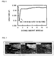
- a dispersion liquid was prepared by dispersing polystyrene particles each having a diameter of 1,000 nm (marketed as “Research Polystyrene Particles 5100A”; manufactured by MORITEX Corporation) in a concentration of 40.5% by mass. Under the same conditions as in Reference Example 1, changes in concentration of particles in the process of film formation were traced with use of a capacitance meter (marketed as "Microsense 4800"; manufactured by KLA-Tencor). The results are shown in Fig. 6 .
- a dispersion liquid was prepared by dispersing Au particles each having a diameter of 15 nm in water in a concentration of 5.0% by mass.
- the Au particles were synthesized by a method described in Japanese Journal of Applied Physics 2001, 40, 346-349 .
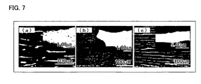
- particle films each having a size of 30 ⁇ 60 mm 2 were formed on the first substrate while moving the first substrate at a film-forming speed of 1.25 ⁇ m/s and applying electric fields of 0 V/cm, 60 V/cm, and 100 V/cm between the substrates, respectively.
- the first substrate was a silicon substrate coated with a binder layer.
- the silicon substrate coated with the binder layer was prepared as follows: A solution was prepared by dissolving polystyrene (marketed as "Polystyrene”; manufactured by Kishida Chemicals Co., Ltd.) in toluene, and a silicon substrate having a thickness of 0.7 mm was spin-coated with the solution so that the solution formed into a binder layer of polystyrene having a thickness of 20 nm or smaller. Further, the second substrate used was made of ITO glass. The first substrate and the second substrate were placed at a distance of 50 ⁇ m from each other, with the second substrate at an angle of 0.14° to the plane of the first substrate.
- a dispersion liquid was prepared by dispersing Au particles each having a diameter of 15 nm in water in a concentration of 1% by mass.
- the dispersion liquid is identical to that used in Reference Example 4.
- particle films each having a size of 30 ⁇ 60 mm 2 were formed on the first substrate while moving the first substrate at a film-forming speed of 0.1 mm/s and applying electric fields of 100 V/cm, 60 V/cm, and 0 V/cm stepwise between the substrates, respectively.
- the first substrate was a silicon substrate coated with a binder layer.
- the silicon substrate coated with the binder layer was prepared as follows: A solution was prepared by dissolving polystyrene (marketed as "Polystyrene”; manufactured by Kishida Chemicals Co., Ltd.) in toluene, and a silicon substrate having a thickness of 0.7 mm was spin-coated with the solution so that the solution formed into a binder layer of polystyrene having a thickness of 20 nm or smaller.
- polystyrene marketed as "Polystyrene”; manufactured by Kishida Chemicals Co., Ltd.
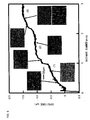
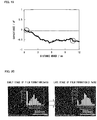
- Fig. 8 The results are shown in Fig. 8 .
- the vertical axis represents capacitance, which takes on smaller values as it goes up.
- the horizontal axis represents position information of the substrate during film formation.
- a voltage of 100 V/cm was applied (see Area 1 in Fig. 8 ). After that, the applied voltage was lowered from 100 V/cm to 60 V/cm, which results in a significant decrease in capacitance (see Area 2 in Fig. 8 ). Then, finally, the applied voltage was lowered to 0 V/cm, which resulted, similarly, in a significant decrease in capacitance (see Area 3 in Fig. 8 ).
- the monolayer films were measured with an SEM in each area (see Fig. 8 ). In the result, it was confirmed that the particles films thus obtained had different film densities corresponding to different values of capacitance.
- a silicon wafer (cut wafer) cut out into a size of 30 ⁇ 60 mm 2 was used as the first substrate.
- the cut wafer was fixed to the apparatus by vacuum chucking.
- a cylindrical capacitance probe (marketed as "2810"; manufactured by KLA-Tencor) whose sensing area has a diameter of 10 mm was fixed at a height of 1.03 mm vertically above a surface of the silicon wafer from the middle of a short side of the cut wafer.
- a stepping motor was used to move only the first substrate at a speed of 1,000 ⁇ m/s uniaxially along a long side (X axis) of the cut wafer. The results are shown in Fig. 15 .
- aqueous solution containing 5% by weight of gold nanoparticles each having a diameter of 12 nm was introduced into a space between the first substrate (silicon wafer) and the second substrate (quartz).
- the gold particles were synthesized by a method described in Japanese Journal of Applied Physics 2001, 40, 346-349 . As in the experiments above, only the first substrate was scanned uniaxially at a speed of 1,000 ⁇ m/s.
- the nanoparticle concentration was obtained by correcting the measured capacitance values, with use of the prepared database of capacitance changes based solely on bending of the first substrate, so that capacitance changes based solely on bending of the substrate were cut to zero. It should be noted the pitch of measurement was 10 times/ second.
- a dispersion aqueous solution containing 5% by weight of nanoparticles was fed continuously at a speed of 12 L/h with use of a syringe pump so that there were substantially no changes in nanoparticle concentration.
- a graph of the distribution of particle density as shown in Fig. 18 is one obtained by inference from the SEM data obtained.
- a particle film was produced by carrying the operation as in Example 2, except that a dispersion aqueous solution containing 5% by weight of nanoparticles was not fed with use of a syringe pump, so that there were substantially no changes in nanoparticle concentration.
- a graph of the distribution of particle density as shown in Fig. 20 is one obtained by inference from the SEM data obtained.
- a method of the present invention for producing a particle film can form a particle film uniformly even on a substrate of a practical size. As such, the method can be suitably used for various purposes that require the formation of a particle film on a substrate.
Landscapes
- Life Sciences & Earth Sciences (AREA)
- Engineering & Computer Science (AREA)
- Wood Science & Technology (AREA)
- Investigating Or Analyzing Materials By The Use Of Electric Means (AREA)
- Application Of Or Painting With Fluid Materials (AREA)
- Liquid Deposition Of Substances Of Which Semiconductor Devices Are Composed (AREA)
- Coating Apparatus (AREA)
Applications Claiming Priority (2)
| Application Number | Priority Date | Filing Date | Title |
|---|---|---|---|
| JP2009033063 | 2009-02-16 | ||
| PCT/JP2010/000933 WO2010092836A1 (fr) | 2009-02-16 | 2010-02-16 | Dispositif pour produire un film de particules et procédé de production de ce film |
Publications (3)
| Publication Number | Publication Date |
|---|---|
| EP2397230A1 true EP2397230A1 (fr) | 2011-12-21 |
| EP2397230A4 EP2397230A4 (fr) | 2013-05-15 |
| EP2397230B1 EP2397230B1 (fr) | 2014-10-01 |
Family
ID=42561683
Family Applications (1)
| Application Number | Title | Priority Date | Filing Date |
|---|---|---|---|
| EP10741116.7A Not-in-force EP2397230B1 (fr) | 2009-02-16 | 2010-02-16 | Dispositif pour produire un film de particules et procédé de production de ce film |
Country Status (5)
| Country | Link |
|---|---|
| US (1) | US9333529B2 (fr) |
| EP (1) | EP2397230B1 (fr) |
| JP (1) | JP5322245B2 (fr) |
| KR (1) | KR101362555B1 (fr) |
| WO (1) | WO2010092836A1 (fr) |
Cited By (3)
| Publication number | Priority date | Publication date | Assignee | Title |
|---|---|---|---|---|
| WO2019068857A1 (fr) * | 2017-10-05 | 2019-04-11 | Centre National De La Recherche Scientifique | Procede d'assemblage de particules gravitationnel |
| WO2019179794A1 (fr) * | 2018-03-23 | 2019-09-26 | Uniwersytet Jagiellonski | Réalisation d'une réaction dans un ménisque déplacé sur un substrat |
| WO2019185357A1 (fr) * | 2018-03-28 | 2019-10-03 | Uniwersytet Jagiellonski | Production de films nanoporeux d'oxydes métalliques semi-conducteurs |
Families Citing this family (2)
| Publication number | Priority date | Publication date | Assignee | Title |
|---|---|---|---|---|
| KR20150058860A (ko) * | 2013-11-21 | 2015-05-29 | 한국기계연구원 | 대면적기판 나노입자 코팅장치 |
| KR101682330B1 (ko) * | 2016-04-18 | 2016-12-12 | 서강대학교산학협력단 | 미세 패턴 형성장치 및 미세 패턴 형성방법 |
Citations (3)
| Publication number | Priority date | Publication date | Assignee | Title |
|---|---|---|---|---|
| FR1537039A (fr) * | 1967-06-27 | 1968-08-23 | Glaverbel | Procédé de dépôt d'un liquide sur une surface |
| EP0640406A1 (fr) * | 1993-08-31 | 1995-03-01 | Research Development Corporation Of Japan | Procédé pour fabriquer des films de particules |
| WO2008014604A1 (fr) * | 2006-08-02 | 2008-02-07 | Nanometrix Inc. | Appareil de transfert modulaire et procédé |
Family Cites Families (9)
| Publication number | Priority date | Publication date | Assignee | Title |
|---|---|---|---|---|
| US4911950A (en) | 1986-06-30 | 1990-03-27 | Matsushita Electric Industrial Co., Ltd. | Method of smoothing magnetic film |
| JPS639019A (ja) * | 1986-06-30 | 1988-01-14 | Matsushita Electric Ind Co Ltd | 磁性塗膜の平滑化方法 |
| JPH06234219A (ja) | 1991-04-19 | 1994-08-23 | Okaya Electric Ind Co Ltd | 液滴噴射方法および装置 |
| US5270079A (en) | 1992-12-18 | 1993-12-14 | Specialty Coatings Systems, Inc. | Methods of meniscus coating |
| JPH0810675A (ja) * | 1994-06-30 | 1996-01-16 | Central Glass Co Ltd | 薄膜のコーティング方法 |
| DE4445985A1 (de) * | 1994-12-22 | 1996-06-27 | Steag Micro Tech Gmbh | Verfahren und Vorrichtung zur Belackung oder Beschichtung eines Substrats |
| JP3836992B2 (ja) * | 1999-02-03 | 2006-10-25 | ローム株式会社 | 基板への粘性流体の塗布方法 |
| US6828800B2 (en) * | 2000-12-14 | 2004-12-07 | Yeda Research And Development Co. Ltd. | Single-molecule detector |
| JP2010155218A (ja) | 2008-12-27 | 2010-07-15 | Osaka Univ | 微粒子単層膜付き基板の製造方法及び微粒子単層膜付き基板 |
-
2010
- 2010-02-16 WO PCT/JP2010/000933 patent/WO2010092836A1/fr active Application Filing
- 2010-02-16 US US13/201,017 patent/US9333529B2/en not_active Expired - Fee Related
- 2010-02-16 EP EP10741116.7A patent/EP2397230B1/fr not_active Not-in-force
- 2010-02-16 JP JP2010550476A patent/JP5322245B2/ja not_active Expired - Fee Related
- 2010-02-16 KR KR1020117020993A patent/KR101362555B1/ko not_active IP Right Cessation
Patent Citations (3)
| Publication number | Priority date | Publication date | Assignee | Title |
|---|---|---|---|---|
| FR1537039A (fr) * | 1967-06-27 | 1968-08-23 | Glaverbel | Procédé de dépôt d'un liquide sur une surface |
| EP0640406A1 (fr) * | 1993-08-31 | 1995-03-01 | Research Development Corporation Of Japan | Procédé pour fabriquer des films de particules |
| WO2008014604A1 (fr) * | 2006-08-02 | 2008-02-07 | Nanometrix Inc. | Appareil de transfert modulaire et procédé |
Non-Patent Citations (1)
| Title |
|---|
| See also references of WO2010092836A1 * |
Cited By (4)
| Publication number | Priority date | Publication date | Assignee | Title |
|---|---|---|---|---|
| WO2019068857A1 (fr) * | 2017-10-05 | 2019-04-11 | Centre National De La Recherche Scientifique | Procede d'assemblage de particules gravitationnel |
| FR3072038A1 (fr) * | 2017-10-05 | 2019-04-12 | Centre National De La Recherche Scientifique | Procede d'assemblage de particules gravitationnel |
| WO2019179794A1 (fr) * | 2018-03-23 | 2019-09-26 | Uniwersytet Jagiellonski | Réalisation d'une réaction dans un ménisque déplacé sur un substrat |
| WO2019185357A1 (fr) * | 2018-03-28 | 2019-10-03 | Uniwersytet Jagiellonski | Production de films nanoporeux d'oxydes métalliques semi-conducteurs |
Also Published As
| Publication number | Publication date |
|---|---|
| KR20110115162A (ko) | 2011-10-20 |
| WO2010092836A1 (fr) | 2010-08-19 |
| US20110315052A1 (en) | 2011-12-29 |
| US9333529B2 (en) | 2016-05-10 |
| KR101362555B1 (ko) | 2014-02-13 |
| EP2397230A4 (fr) | 2013-05-15 |
| EP2397230B1 (fr) | 2014-10-01 |
| JP5322245B2 (ja) | 2013-10-23 |
| JPWO2010092836A1 (ja) | 2012-08-16 |
Similar Documents
| Publication | Publication Date | Title |
|---|---|---|
| EP2397230B1 (fr) | Dispositif pour produire un film de particules et procédé de production de ce film | |
| Laaksonen et al. | Quantised charging of monolayer-protected nanoparticles | |
| US10233559B2 (en) | High rate electric field driven nanoelement assembly on an insulated surface | |
| Hüsser et al. | High‐resolution deposition and etching of metals with a scanning electrochemical microscope | |
| CN111457833A (zh) | 基于立体电极结构的柔性弯曲传感器及加工方法 | |
| Yoo et al. | Mapping drift in morphology and electrical performance in aerosol jet printing | |
| JPS60185151A (ja) | 金属層の電気抵抗測定方法 | |
| Hensel et al. | Automated self-assembly and electrical characterization of nanostructured films | |
| Stussi et al. | Fabrication of conducting polymer patterns for gas sensing by a dry technique | |
| CN114501863B (zh) | 一种刮涂对位校准的装置及方法 | |
| KR20190033043A (ko) | 나노소재의 무전극 전자이동도 측정장치, 나노소재의 무전극 정공이동도 측정장치, 나노소재의 무전극 전자이동도 측정방법 및 나노소재의 무전극 정공이동도 측정방법 | |
| Jaffrezic-Renault et al. | Study of the silicon nitride/aqueous electrolyte interface on colloidal aqueous suspensions and on electrolyte/insulator/semiconductor structures | |
| Wang et al. | Measurement of double-layer forces at the polymer film/electrolyte interfaces using atomic force microscopy: concentration and potential-dependent interactions | |
| JP6583808B2 (ja) | 有機半導体膜の製造方法および製造装置 | |
| JP2001133615A (ja) | 回折格子製作方法および製作装置 | |
| CN104075973B (zh) | 一种无损测量纳米线阵列比表面积和密集度的装置及方法 | |
| Beshajová Pelikánová et al. | The Nonconductive Sputtered Thin Film Layer | |
| Kinder et al. | Carrier profiling of a heterojunction bipolar transistor and p–i–n photodiode structures by electrochemical C–V technique | |
| Suehiro et al. | Electrospray Deposition of {200} Oriented Regular-Assembly BaTiO3 Nanocrystal Films under an Electric Field | |
| Wang et al. | Origin of Capillary-Force-Induced Welding in Ag Nanowires and Ag Nanowire/Carbon Nanotube Conductive Networks | |
| Klaas et al. | Development of a Humidity Sensor Element based on sputter-deposited thin ZnO-Layers | |
| ES2936322T3 (es) | Dispositivo y procedimiento para aplicar medios líquidos sobre una superficie de sustrato | |
| EP3214207A1 (fr) | Procédé de production de nanofils d'antimoine | |
| EP3775326B1 (fr) | Production de films nanoporeux d'oxydes métalliques semi-conducteurs | |
| Sabah et al. | pH Sensing characteristics of CuS/ZnO thin film implemented as EGFET |
Legal Events
| Date | Code | Title | Description |
|---|---|---|---|
| PUAI | Public reference made under article 153(3) epc to a published international application that has entered the european phase |
Free format text: ORIGINAL CODE: 0009012 |
|
| 17P | Request for examination filed |
Effective date: 20110825 |
|
| AK | Designated contracting states |
Kind code of ref document: A1 Designated state(s): AT BE BG CH CY CZ DE DK EE ES FI FR GB GR HR HU IE IS IT LI LT LU LV MC MK MT NL NO PL PT RO SE SI SK SM TR |
|
| DAX | Request for extension of the european patent (deleted) | ||
| A4 | Supplementary search report drawn up and despatched |
Effective date: 20130415 |
|
| RIC1 | Information provided on ipc code assigned before grant |
Ipc: B05C 11/00 20060101ALI20130409BHEP Ipc: B05D 7/24 20060101ALI20130409BHEP Ipc: B05C 3/18 20060101AFI20130409BHEP Ipc: B05D 1/00 20060101ALI20130409BHEP Ipc: B05D 3/00 20060101ALI20130409BHEP |
|
| RIC1 | Information provided on ipc code assigned before grant |
Ipc: B05D 1/00 20060101ALI20140122BHEP Ipc: B05D 7/24 20060101ALI20140122BHEP Ipc: B05C 11/00 20060101ALI20140122BHEP Ipc: B05C 3/18 20060101AFI20140122BHEP Ipc: B05D 3/00 20060101ALI20140122BHEP |
|
| GRAP | Despatch of communication of intention to grant a patent |
Free format text: ORIGINAL CODE: EPIDOSNIGR1 |
|
| INTG | Intention to grant announced |
Effective date: 20140516 |
|
| GRAS | Grant fee paid |
Free format text: ORIGINAL CODE: EPIDOSNIGR3 |
|
| GRAA | (expected) grant |
Free format text: ORIGINAL CODE: 0009210 |
|
| AK | Designated contracting states |
Kind code of ref document: B1 Designated state(s): AT BE BG CH CY CZ DE DK EE ES FI FR GB GR HR HU IE IS IT LI LT LU LV MC MK MT NL NO PL PT RO SE SI SK SM TR |
|
| REG | Reference to a national code |
Ref country code: GB Ref legal event code: FG4D |
|
| REG | Reference to a national code |
Ref country code: CH Ref legal event code: EP Ref country code: AT Ref legal event code: REF Ref document number: 689237 Country of ref document: AT Kind code of ref document: T Effective date: 20141015 |
|
| REG | Reference to a national code |
Ref country code: IE Ref legal event code: FG4D |
|
| REG | Reference to a national code |
Ref country code: DE Ref legal event code: R096 Ref document number: 602010019252 Country of ref document: DE Effective date: 20141113 |
|
| REG | Reference to a national code |
Ref country code: NL Ref legal event code: VDEP Effective date: 20141001 |
|
| REG | Reference to a national code |
Ref country code: AT Ref legal event code: MK05 Ref document number: 689237 Country of ref document: AT Kind code of ref document: T Effective date: 20141001 |
|
| REG | Reference to a national code |
Ref country code: LT Ref legal event code: MG4D |
|
| PG25 | Lapsed in a contracting state [announced via postgrant information from national office to epo] |
Ref country code: NL Free format text: LAPSE BECAUSE OF FAILURE TO SUBMIT A TRANSLATION OF THE DESCRIPTION OR TO PAY THE FEE WITHIN THE PRESCRIBED TIME-LIMIT Effective date: 20141001 |
|
| PG25 | Lapsed in a contracting state [announced via postgrant information from national office to epo] |
Ref country code: LT Free format text: LAPSE BECAUSE OF FAILURE TO SUBMIT A TRANSLATION OF THE DESCRIPTION OR TO PAY THE FEE WITHIN THE PRESCRIBED TIME-LIMIT Effective date: 20141001 Ref country code: FI Free format text: LAPSE BECAUSE OF FAILURE TO SUBMIT A TRANSLATION OF THE DESCRIPTION OR TO PAY THE FEE WITHIN THE PRESCRIBED TIME-LIMIT Effective date: 20141001 Ref country code: CZ Free format text: LAPSE BECAUSE OF FAILURE TO SUBMIT A TRANSLATION OF THE DESCRIPTION OR TO PAY THE FEE WITHIN THE PRESCRIBED TIME-LIMIT Effective date: 20141001 Ref country code: NO Free format text: LAPSE BECAUSE OF FAILURE TO SUBMIT A TRANSLATION OF THE DESCRIPTION OR TO PAY THE FEE WITHIN THE PRESCRIBED TIME-LIMIT Effective date: 20150101 Ref country code: IS Free format text: LAPSE BECAUSE OF FAILURE TO SUBMIT A TRANSLATION OF THE DESCRIPTION OR TO PAY THE FEE WITHIN THE PRESCRIBED TIME-LIMIT Effective date: 20150201 Ref country code: PT Free format text: LAPSE BECAUSE OF FAILURE TO SUBMIT A TRANSLATION OF THE DESCRIPTION OR TO PAY THE FEE WITHIN THE PRESCRIBED TIME-LIMIT Effective date: 20150202 Ref country code: ES Free format text: LAPSE BECAUSE OF FAILURE TO SUBMIT A TRANSLATION OF THE DESCRIPTION OR TO PAY THE FEE WITHIN THE PRESCRIBED TIME-LIMIT Effective date: 20141001 |
|
| PG25 | Lapsed in a contracting state [announced via postgrant information from national office to epo] |
Ref country code: LV Free format text: LAPSE BECAUSE OF FAILURE TO SUBMIT A TRANSLATION OF THE DESCRIPTION OR TO PAY THE FEE WITHIN THE PRESCRIBED TIME-LIMIT Effective date: 20141001 Ref country code: SE Free format text: LAPSE BECAUSE OF FAILURE TO SUBMIT A TRANSLATION OF THE DESCRIPTION OR TO PAY THE FEE WITHIN THE PRESCRIBED TIME-LIMIT Effective date: 20141001 Ref country code: PL Free format text: LAPSE BECAUSE OF FAILURE TO SUBMIT A TRANSLATION OF THE DESCRIPTION OR TO PAY THE FEE WITHIN THE PRESCRIBED TIME-LIMIT Effective date: 20141001 Ref country code: AT Free format text: LAPSE BECAUSE OF FAILURE TO SUBMIT A TRANSLATION OF THE DESCRIPTION OR TO PAY THE FEE WITHIN THE PRESCRIBED TIME-LIMIT Effective date: 20141001 Ref country code: CY Free format text: LAPSE BECAUSE OF FAILURE TO SUBMIT A TRANSLATION OF THE DESCRIPTION OR TO PAY THE FEE WITHIN THE PRESCRIBED TIME-LIMIT Effective date: 20141001 Ref country code: GR Free format text: LAPSE BECAUSE OF FAILURE TO SUBMIT A TRANSLATION OF THE DESCRIPTION OR TO PAY THE FEE WITHIN THE PRESCRIBED TIME-LIMIT Effective date: 20150102 Ref country code: HR Free format text: LAPSE BECAUSE OF FAILURE TO SUBMIT A TRANSLATION OF THE DESCRIPTION OR TO PAY THE FEE WITHIN THE PRESCRIBED TIME-LIMIT Effective date: 20141001 |
|
| PG25 | Lapsed in a contracting state [announced via postgrant information from national office to epo] |
Ref country code: BE Free format text: LAPSE BECAUSE OF NON-PAYMENT OF DUE FEES Effective date: 20150228 |
|
| REG | Reference to a national code |
Ref country code: DE Ref legal event code: R097 Ref document number: 602010019252 Country of ref document: DE |
|
| PG25 | Lapsed in a contracting state [announced via postgrant information from national office to epo] |
Ref country code: EE Free format text: LAPSE BECAUSE OF FAILURE TO SUBMIT A TRANSLATION OF THE DESCRIPTION OR TO PAY THE FEE WITHIN THE PRESCRIBED TIME-LIMIT Effective date: 20141001 Ref country code: SK Free format text: LAPSE BECAUSE OF FAILURE TO SUBMIT A TRANSLATION OF THE DESCRIPTION OR TO PAY THE FEE WITHIN THE PRESCRIBED TIME-LIMIT Effective date: 20141001 Ref country code: DK Free format text: LAPSE BECAUSE OF FAILURE TO SUBMIT A TRANSLATION OF THE DESCRIPTION OR TO PAY THE FEE WITHIN THE PRESCRIBED TIME-LIMIT Effective date: 20141001 Ref country code: RO Free format text: LAPSE BECAUSE OF FAILURE TO SUBMIT A TRANSLATION OF THE DESCRIPTION OR TO PAY THE FEE WITHIN THE PRESCRIBED TIME-LIMIT Effective date: 20141001 |
|
| PLBE | No opposition filed within time limit |
Free format text: ORIGINAL CODE: 0009261 |
|
| STAA | Information on the status of an ep patent application or granted ep patent |
Free format text: STATUS: NO OPPOSITION FILED WITHIN TIME LIMIT |
|
| PG25 | Lapsed in a contracting state [announced via postgrant information from national office to epo] |
Ref country code: IT Free format text: LAPSE BECAUSE OF FAILURE TO SUBMIT A TRANSLATION OF THE DESCRIPTION OR TO PAY THE FEE WITHIN THE PRESCRIBED TIME-LIMIT Effective date: 20141001 |
|
| 26N | No opposition filed |
Effective date: 20150702 |
|
| PG25 | Lapsed in a contracting state [announced via postgrant information from national office to epo] |
Ref country code: LU Free format text: LAPSE BECAUSE OF FAILURE TO SUBMIT A TRANSLATION OF THE DESCRIPTION OR TO PAY THE FEE WITHIN THE PRESCRIBED TIME-LIMIT Effective date: 20150216 |
|
| REG | Reference to a national code |
Ref country code: CH Ref legal event code: PL |
|
| GBPC | Gb: european patent ceased through non-payment of renewal fee |
Effective date: 20150216 |
|
| PG25 | Lapsed in a contracting state [announced via postgrant information from national office to epo] |
Ref country code: CH Free format text: LAPSE BECAUSE OF NON-PAYMENT OF DUE FEES Effective date: 20150228 Ref country code: MC Free format text: LAPSE BECAUSE OF FAILURE TO SUBMIT A TRANSLATION OF THE DESCRIPTION OR TO PAY THE FEE WITHIN THE PRESCRIBED TIME-LIMIT Effective date: 20141001 Ref country code: LI Free format text: LAPSE BECAUSE OF NON-PAYMENT OF DUE FEES Effective date: 20150228 |
|
| REG | Reference to a national code |
Ref country code: IE Ref legal event code: MM4A |
|
| REG | Reference to a national code |
Ref country code: FR Ref legal event code: ST Effective date: 20151030 |
|
| PG25 | Lapsed in a contracting state [announced via postgrant information from national office to epo] |
Ref country code: GB Free format text: LAPSE BECAUSE OF NON-PAYMENT OF DUE FEES Effective date: 20150216 Ref country code: IE Free format text: LAPSE BECAUSE OF NON-PAYMENT OF DUE FEES Effective date: 20150216 |
|
| PG25 | Lapsed in a contracting state [announced via postgrant information from national office to epo] |
Ref country code: SI Free format text: LAPSE BECAUSE OF FAILURE TO SUBMIT A TRANSLATION OF THE DESCRIPTION OR TO PAY THE FEE WITHIN THE PRESCRIBED TIME-LIMIT Effective date: 20141001 Ref country code: FR Free format text: LAPSE BECAUSE OF NON-PAYMENT OF DUE FEES Effective date: 20150302 |
|
| PG25 | Lapsed in a contracting state [announced via postgrant information from national office to epo] |
Ref country code: MT Free format text: LAPSE BECAUSE OF FAILURE TO SUBMIT A TRANSLATION OF THE DESCRIPTION OR TO PAY THE FEE WITHIN THE PRESCRIBED TIME-LIMIT Effective date: 20141001 |
|
| PG25 | Lapsed in a contracting state [announced via postgrant information from national office to epo] |
Ref country code: BG Free format text: LAPSE BECAUSE OF FAILURE TO SUBMIT A TRANSLATION OF THE DESCRIPTION OR TO PAY THE FEE WITHIN THE PRESCRIBED TIME-LIMIT Effective date: 20141001 Ref country code: SM Free format text: LAPSE BECAUSE OF FAILURE TO SUBMIT A TRANSLATION OF THE DESCRIPTION OR TO PAY THE FEE WITHIN THE PRESCRIBED TIME-LIMIT Effective date: 20141001 Ref country code: HU Free format text: LAPSE BECAUSE OF FAILURE TO SUBMIT A TRANSLATION OF THE DESCRIPTION OR TO PAY THE FEE WITHIN THE PRESCRIBED TIME-LIMIT; INVALID AB INITIO Effective date: 20100216 |
|
| PG25 | Lapsed in a contracting state [announced via postgrant information from national office to epo] |
Ref country code: TR Free format text: LAPSE BECAUSE OF FAILURE TO SUBMIT A TRANSLATION OF THE DESCRIPTION OR TO PAY THE FEE WITHIN THE PRESCRIBED TIME-LIMIT Effective date: 20141001 |
|
| PGFP | Annual fee paid to national office [announced via postgrant information from national office to epo] |
Ref country code: DE Payment date: 20180219 Year of fee payment: 9 |
|
| PG25 | Lapsed in a contracting state [announced via postgrant information from national office to epo] |
Ref country code: MK Free format text: LAPSE BECAUSE OF FAILURE TO SUBMIT A TRANSLATION OF THE DESCRIPTION OR TO PAY THE FEE WITHIN THE PRESCRIBED TIME-LIMIT Effective date: 20141001 |
|
| REG | Reference to a national code |
Ref country code: DE Ref legal event code: R119 Ref document number: 602010019252 Country of ref document: DE |
|
| PG25 | Lapsed in a contracting state [announced via postgrant information from national office to epo] |
Ref country code: DE Free format text: LAPSE BECAUSE OF NON-PAYMENT OF DUE FEES Effective date: 20190903 |