EP2396575B1 - Joints d'étanchéité plats avec élément d'étanchéité supplémentaire - Google Patents
Joints d'étanchéité plats avec élément d'étanchéité supplémentaire Download PDFInfo
- Publication number
- EP2396575B1 EP2396575B1 EP09748033.9A EP09748033A EP2396575B1 EP 2396575 B1 EP2396575 B1 EP 2396575B1 EP 09748033 A EP09748033 A EP 09748033A EP 2396575 B1 EP2396575 B1 EP 2396575B1
- Authority
- EP
- European Patent Office
- Prior art keywords
- stopper
- sealed
- sealing
- beads
- bead
- Prior art date
- Legal status (The legal status is an assumption and is not a legal conclusion. Google has not performed a legal analysis and makes no representation as to the accuracy of the status listed.)
- Not-in-force
Links
Images
Classifications
-
- F—MECHANICAL ENGINEERING; LIGHTING; HEATING; WEAPONS; BLASTING
- F16—ENGINEERING ELEMENTS AND UNITS; GENERAL MEASURES FOR PRODUCING AND MAINTAINING EFFECTIVE FUNCTIONING OF MACHINES OR INSTALLATIONS; THERMAL INSULATION IN GENERAL
- F16J—PISTONS; CYLINDERS; SEALINGS
- F16J15/00—Sealings
- F16J15/02—Sealings between relatively-stationary surfaces
- F16J15/06—Sealings between relatively-stationary surfaces with solid packing compressed between sealing surfaces
- F16J15/08—Sealings between relatively-stationary surfaces with solid packing compressed between sealing surfaces with exclusively metal packing
- F16J15/0818—Flat gaskets
- F16J15/0825—Flat gaskets laminated
-
- F—MECHANICAL ENGINEERING; LIGHTING; HEATING; WEAPONS; BLASTING
- F16—ENGINEERING ELEMENTS AND UNITS; GENERAL MEASURES FOR PRODUCING AND MAINTAINING EFFECTIVE FUNCTIONING OF MACHINES OR INSTALLATIONS; THERMAL INSULATION IN GENERAL
- F16J—PISTONS; CYLINDERS; SEALINGS
- F16J15/00—Sealings
- F16J15/02—Sealings between relatively-stationary surfaces
- F16J15/06—Sealings between relatively-stationary surfaces with solid packing compressed between sealing surfaces
- F16J15/08—Sealings between relatively-stationary surfaces with solid packing compressed between sealing surfaces with exclusively metal packing
- F16J15/0818—Flat gaskets
- F16J2015/085—Flat gaskets without fold over
-
- F—MECHANICAL ENGINEERING; LIGHTING; HEATING; WEAPONS; BLASTING
- F16—ENGINEERING ELEMENTS AND UNITS; GENERAL MEASURES FOR PRODUCING AND MAINTAINING EFFECTIVE FUNCTIONING OF MACHINES OR INSTALLATIONS; THERMAL INSULATION IN GENERAL
- F16J—PISTONS; CYLINDERS; SEALINGS
- F16J15/00—Sealings
- F16J15/02—Sealings between relatively-stationary surfaces
- F16J15/06—Sealings between relatively-stationary surfaces with solid packing compressed between sealing surfaces
- F16J15/08—Sealings between relatively-stationary surfaces with solid packing compressed between sealing surfaces with exclusively metal packing
- F16J15/0818—Flat gaskets
- F16J2015/0862—Flat gaskets with a bore ring
Definitions
- the present invention relates to a flat gasket, in particular for internal combustion engines, such as a cylinder head gasket, a gasket in the region of the exhaust gas supply or exhaust gas discharge of turbochargers or a gasket in the region of exhaust gas recirculation.
- Flat seals such as cylinder head gaskets dense combustion chambers, medium passages such as coolant, lubricant and exhaust gas passages and screw holes. They are force mediators between the components to be sealed, for example engine block and cylinder head, and thus have a considerable influence on the distribution of forces in the overall system.
- cylinder head gaskets must seal off gas-tight and at the same time seal motor oil and cooling water channels securely against liquid leakage.
- a conventional gasket is eg off DE 200 21 017 U known.
- Classic soft material flat gaskets can, for example, consist of a spliced carrier sheet to which soft material is applied on both sides, for example by rolling.
- Metallic enclosures may be provided to seal the combustion chambers, fluid passages and screw holes and protect the soft material from overheating. Impregnation of the fabric surface may prevent swelling by contact with the media, such as oil, water, antifreeze, or other liquids or gases.
- So-called Viton elements preferably of elastomeric materials, may be provided to provide a partial increase in surface pressure in predetermined areas, e.g. Allow oil pressure holes. Due to the surface pressure, the material is deformed so that it adapts to the surfaces to be sealed. For the sealing comparatively high clamping forces with low springback properties are required.
- multi-layer or multi-layer steel gaskets can be used.
- Such multi-layer steel seals consist of two or more sealing functional layers of, for example, spring or carbon steel sheets stacked into a multi-layer steel flat gasket.
- the present invention provides an improved flat seal which is adaptable in terms of its sealing function.
- the object of the present invention is achieved by a bead, in particular at least one half-bead or full bead, which is connected upstream of the sealing function of the flat gasket.
- a flat gasket with one or more stopper functional layers according to claim 1 is provided, which is provided in particular for use with internal combustion engines as a cylinder head gasket, in the area of the exhaust gas supply or exhaust gas discharge from turbochargers or in the area of exhaust gas recirculation.
- the flat gasket has one or more upstream beads with regard to at least one stopper of the one or more stopper functional layers. Deck and floor functional position are preferably symmetrical.
- the flat gasket with respect to its sealing function with respect to the stopper on one or more downstream beads.
- the flat gasket is a multi-layer gasket.
- the gasket is a multi-layer steel gasket (MLS gasket).
- At least one of the upstream corrugations (50, 55) seals against at least one insert component (80) which is provided in at least one sealing surface of an at least two-part component to be sealed (60, 65) and the sealing function of the upstream corrugation (50 , 55) is obtained by compressing the upstream bead (50, 55) with a surface of the insert member (80).
- the insert member (80) has a variable or constant overhang or shed or a combination thereof with respect to the respective sealing surface of a component of the two-piece component (60, 65).
- the beads are full beads and / or half beads.
- At least one of the components of the two-part component has a channel which terminates in a region of the sealing surface of the respective component.
- the region in which the channel ends corresponds to a region with respect to the flat seal between the sealing region of the upstream bead and the sealing region of the Stoppers.
- cylinder head gaskets in particular multi-layer steel cylinder head gaskets (MLS cylinder head gaskets).
- teachings of the invention are not limited to the field of multi-layer steel cylinder head gaskets for internal combustion engines.
- teaching of the invention can be applied to further flat gaskets which are used in particular in the field of internal combustion engines, for example gaskets in the exhaust gas supply or exhaust gas removal of turbochargers or in the area of exhaust gas recirculation.
- the teaching of the invention is not limited to multi-layer steel flat gaskets (MLS gaskets) but can also find application in the field of multilayer flat gaskets.
- MLS flat gaskets or MLS cylinder head gaskets are to be regarded as respective special cases of multilayer gaskets.
- Cylinder head gaskets are flat gaskets that seal against each other under technologically demanding conditions, combustion chambers, coolant and lubricant feedthroughs as well as fastening bushings (in particular screw lead-throughs).
- the cylinder head gasket here is force mediator between the cylinder head and the engine block and thus has a significant influence on the power distribution in the engine as a whole.
- cylinder head densities with one or more layers, in particular steel layers. Currently, up to five layers are used, but this is not meant to be limiting.
- the basic structure of a multi-layer gasket, such as a cylinder head gasket includes a top and bottom layer as functional layers.
- At least one of these functional layers is beaded, preferably the cover or bottom functional layers are congruently beaded, and are preferably made of steel, such as spring steel or spring-hard stainless steels.
- the beads are introduced by embossing, for example.
- the cover and bottom functional position in the region of the bead must have a suitable spring property and tensile strength for the intended application.
- defined beads generate line pressures in the region of the sealing surfaces of the components to be sealed due to the elastic properties of the cover and bottom functional position, for example to seal combustion chambers or media passages such as exhaust gas, coolant or lubricant passages.
- cover or bottom functional layer which are preferably made of spring steel sheet
- four individual lines are formed in a full bead with high line pressure compared to the sealing surfaces of the components to be sealed, while at a half bead due to the property of the deck or floor function position two individual lines are formed with high line pressure.
- full corrugations can compensate for dynamic sealing gap movements and are used, for example, in cylinder head gaskets for sealing combustion chambers.
- Semi-beads produce lower line pressures than full corrugations and are preferably used in cylinder head gaskets for sealing against gas and media such as cooling water and oil and screw holes, and circumferentially seal the outer seal contour. Due to the lower line pressure of the half beads of a cylinder head gasket, the main compression of the full corrugations on the combustion chambers is essentially retained.
- a full bead may typically be characterized by a bead depth Y, a leg angle X, and a head width V.
- a half bead can typically be characterized by a bead depth Y and a leg angle X.
- Next to the geometry quality, thickness and manufacturing process have a significant influence on the properties of the beads. These factors make it possible to produce a large number of different beads with defined load and springback properties, which differ significantly in terms of their characteristic or force absorption. So softer or harder beads can be realized. For example, small-pitch solid beads X are softer and have a flatter spring characteristic and higher creep rupture strength.
- stoppers In addition to corrugations, which form a line pressure in the region of the sealing surfaces of the components to be sealed, so-called stoppers can also be provided by which an increased surface pressure in the region of the sealing surfaces of the components to be sealed can be achieved. Especially with MLS cylinder head gaskets, stoppers are provided in the area of the combustion chamber.
- the so-called stoppers are preferably provided as an active functional layer of a multilayer flat gasket, which is arranged, for example, between the top and bottom functional layer, in order to increase the surface pressure of the flat gasket with the sealing surfaces of the components to be sealed and prevent flattening of the corrugations by an elevation.
- a gasket with a stopper functional layer such as an MLS cylinder head gasket
- beads are crimped to stopper height or to the equilibrium of the sip force and clamping forces of the gasket (e.g., bolt forces). That is, a stopper essentially dictates the installation height of the beads (full corrugations) and the function of the stopper is thereby the limitation of the bead deformation by determining the degree of crimping of the beads.
- a typical height of executed stoppers ranges from a few 1/100 mm about 0.15 mm.
- a stopper can be selected from various grades of steel, from carbon steel to stainless steel, for example
- further functional layers can provide, for example one or more further bonded functional layers, spacer functional layers and / or elastomeric functional layers.
- an elastic / plastic adaptation to the pressure conditions in the space or passage to be sealed can be achieved by appropriate design.
- Elastomeric functional layers may preferably be applied as single or double-sided elastomeric coating on active functional layers, in particular the cover and bottom functional layers, and provide the so-called micro-sealing d.
- H. the seal against the surface roughness of the sealing surfaces of the components to be sealed or between the functional layers of a multilayer flat gasket safely.
- the so-called macro-sealing take over the embossed in functional layers beads or / the stoppers provided by Stopperfunktionslagen stopper.
- By means of controlled contact pressure such a coating fills and compensates for existing roughness, scratches and porosities.
- the coating of the surfaces has corresponding sliding properties in order to prevent so-called "fretting" marks due to micro movements under high surface pressure.
- the functional layers can be coated over the whole area or even only partially, in one or more layers or have one or more special coatings, for example in predetermined areas, which are adapted to the extreme requirements (high temperatures, large sliding movements), for example.
- a (high temperature resistant) fluoropolymer can serve as an elastomer coating.
- the mode of operation of a multilayer flat gasket with a stopper functional position can be represented in a suitable manner using the example of an MLS cylinder head gasket with a stopper.
- the Generality and transferability to multilayer flat gaskets of this representation can be seen immediately.
- the conventional MLS cylinder head gasket corresponds to the design "beading next to the stopper, ie viewed from the combustion chamber edge, the bead is behind the stopper and is thus in the" power shunt. "However, the bead necessary for combustion chamber sealing can not only be next to but also on the side This is the case, for example, with the "bead-on-stopper technology.” The bead then lies in the "force main circuit.”
- the use of the introduced bolt forces is primarily for the gas seal
- an additional second sealing line can be represented by a downstream, circumferential combustion chamber half bead, but the stopper no longer specifies the installation height of the combustion chamber bead in this design principle.
- the stopper of an MLS cylinder head gasket is the first sealing stage against combustion gases in the combustion chamber. Due to the prestressing of the flat gasket between the sealing surfaces of the components to be sealed, the beads are not used at low to medium internal pressure. The sealing takes place exclusively in that the sealing surfaces of the components to be sealed are biased over the area of the stopper. If the stopper then loses contact with increasing interior pressure, take over the downstream of the stopper beads the sealing function.
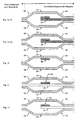
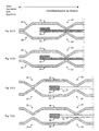
- Fig. 1a . 1d to 1f embodiments of a flat gasket according to the invention are shown schematically in cross section. Between the top and bottom functional layers 10 and 20, a stopper 30 and a stopper functional layer is respectively introduced. According to the type "bead next to stopper" is a bead 40 and 45, the stopper 30 with respect to the sealing function against an interior or passage, which is comprised of two components to be sealed against each other, downstream or downstream.
- a downstream half bead 40 is exemplified, while in the Fig. 1e and 1f in each case a downstream full bead 45 is shown.
- FIG. 1a, 1d to 1f respectively upstream beads 50 and 55 according to embodiments of the present invention, wherein in Fig. 1a a half bead 50 is illustrated as an upstream bead and in FIG Fig. 1f an upstream full bead 55 is illustrated.
- FIG. 1a to 1f different stoppers shown schematically.
- folded or crimped stopper function layers 30 are shown in the non-inventive Fig. 1b a on the deck function layer 10 (alternatively on the bottom function layer 20, not shown) mounted stopper 30, in the non-inventive Fig. 1c an inserted between the top and bottom functional position additional functional layer 35, which is substantially flush with the top or bottom functional position 10, 20 with respect to the inner space or the passage and on which a stopper 30 is applied and in the inventive Fig. 1f an inserted between the top and bottom functional position additional functional layer 35 with a by example, on / welding on / soldering / attached stopper 30 such as a stopper ring 30th
- stopper function positions shown schematically in the figures and the deck and floor function position shown schematically in the figures can be combined as desired.
- a plurality of stopper functional layers and one or more further functional layers such as distance function layers, coating function layers (not shown in the figures) but also further functional layers can be provided with one or more beads, with other functional layers also above and / or below the deck - or soil functional position, ie not only between these, can be arranged.
- several beads can be provided upstream and / or downstream.
- the top and bottom functional layers 10, 20 may be substantially symmetrical / congruent, as schematically illustrated, but the top and bottom functional layers 10, 20 may also include one or more different types of sip, one or more different positions of the sipes, and / or have a different number of beads.
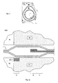
- Fig. 2 shows a schematic plan view of a flat gasket according to an embodiment of the present invention.
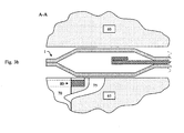
- Fig. 3a and 3b show cuts through the in Fig. 2 illustrated flat gasket according to the invention in the Fig. 2 designated sections.
- Fig. 3a and 3b show a two-part component with cover component 60 and bottom component 65 (such as, for example, an engine block 65 and a cylinder head 60) with a flat gasket 1 according to an embodiment, which is arranged between the components 60 and 65 to be sealed.
- cover component 60 and bottom component 65 such as, for example, an engine block 65 and a cylinder head 60
- flat gasket 1 according to an embodiment, which is arranged between the components 60 and 65 to be sealed.
- a gas opening 70 illustrates the opening to be sealed, the interior to be sealed or passage.
- a leakage of gases or media in the opening, the interior or the passage through a gap which is formed by cover and bottom components 60 and 65 is at least substantially prevented by the arranged and compressed in the intermediate space flat gasket 1.
- an opening such as a gas flow opening 65 may be provided.
- an insert member 80 is provided.
- the insert member 80 may be, for example, a liner ring, but may alternatively have other shapes including the aperture, interior, or passage. That is, the insert member 80 may alternatively be, for example, elliptical, but have substantially any shape encompassing the aperture, interior, or passage.
- the insert member 80 may include a protrusion or shelter with respect to the respective sealing surface, or may be substantially aligned with the respective sealing surface.
- the supernatant of the insert member 80 may be circumferentially variable, i. the insert member 80 may be partially a shelter, partially a supernatant and partially aligned, or any combination thereof be designed.
- the insert member may have a circumferential variable cross-section.
- the insert member 80 may be provided on one of the components 60 and 65 or in both components 60 and 65.
- the insert member 80 may be made of the same material as the members 60 and 65 or another, preferably a metal such as a spring steel.
- the upstream beads 50, 55 may have properties different from those of the downstream beads 40, 45.
- the upstream beads 50, 55 or the beads 50, 55 that come in contact with the insert component 80 may have softer bead characteristics.
- the insert member 80 may have a shelter / supernatant with respect to the respective sealing surface, the compression of the upstream bead (s) and thus their sealing effect (s) is made possible to adapt specifically to a desired requirement profile.
- the stopper of the flat gasket 1 according to the invention is no longer the first sealing stage against media / gases in the opening to be sealed, the interior or the passage. Rather, now realize the upstream beads 50, 55, the first Abdichtcut A.
- the pressure-dependent sealing function of the upstream beads 50, 55 can by means of Insertion member 80 and its shelter / supernatant with respect to the respective sealing surface can be adjusted. Subsequently comes now as the second sealing step B caused by the stopper surface pressure effect. If the stopper then loses contact as the interior pressure increases, the beads downstream of the stopper assume the sealing function as the third sealing stage C.
- the prestressing of the flat gasket between the sealing surfaces of the components to be sealed means that the downstream beads are not used, for example at low to medium internal pressure ,
- the gas flow opening 75 in the illustrated embodiment forms a channel from the opening 70, the interior or the passage.
- the channel of the gas flow opening 75 terminates in a region of the respective sealing surface of the component 65, in which the flat gasket 1 according to the invention is arranged.
- the channel of the gas flow opening 75 terminates in a region of the respective sealing surface of the component 65 which, with the flat gasket 1 according to the invention, a (line) sealing region of the upstream beads 50, 55 and the (surface) sealing region of the stopper 35.
- the adjustable projection / Shelter of the insert member 80 can now be the VerpressCHE of the respective, upstream bead 50 and insert member 80 can be adjusted, ie the Abdichtschreib / sealing function by the first beads relative to the respective component 60, 65 with insert member 80 can be adjusted. Accordingly, the upstream bead loses its sealing function at a predetermined pressure, and gas can flow through the channel 75 of the gas flow port.
Landscapes
- Engineering & Computer Science (AREA)
- General Engineering & Computer Science (AREA)
- Mechanical Engineering (AREA)
- Gasket Seals (AREA)
Claims (7)
- Joint d'étanchéité plat (1) avec au moins une couche nervurée (10, 20) et une ou plusieurs couches à fonction d'arrêt (30, 35), le joint d'étanchéité plat (1) présentant autour d'une ouverture d'étanchéité au moins un arrêt (30) circulaire dans la couche à fonction d'arrêt et au moins une première nervure (50, 55) circulaire placée en avant en référence à la fonction d'étanchéité étant disposée sur un côté de l'arrêt situé en direction de l'ouverture d'étanchéité dans au moins une couche nervurée et sur lequel est disposée au moins une deuxième nervure (40, 45) circulaire placée en arrière du côté de l'arrêt opposé à l'ouverture d'étanchéité caractérisé en ce que la couche à fonction d'arrêt se termine avant la première nervure en direction de l'ouverture d'étanchéité.
- Joint d'étanchéité plat selon la revendication 1 le joint d'étanchéité plat (1) étant un joint d'étanchéité plat multicouches, de préférence un joint d'étanchéité plat en acier à plusieurs couches.
- Joint d'étanchéité plat selon une quelconque des revendications précédentes avec un composant (60, 65) à étanchéifier au moins en deux parties, une au moins des nervures (50, 55) placées en avant servant à étanchéifier vis-à-vis d'au moins un composant encastré (80) prévu dans au moins une surface d'étanchéité du composant (60, 65) à étanchéifier au moins en deux parties et la fonction d'étanchéification de la nervure (50, 55) placée en avant étant obtenue par compression de la nervure (50, 55) placée en avant avec une surface du composant encastré (80).
- Joint d'étanchéité plat selon la revendication 2 avec un composant (60, 65) à étanchéifier au moins en deux parties, un composant encastré (80) présentant une partie en saillie ou une partie inférieure variable ou constante ou une combinaison de celles-ci concernant la surface d'étanchéification respective d'un composant du composant (60, 65) en deux parties.
- Joint d'étanchéité plat selon une quelconque des revendications précédentes pour lequel les nervures placées en avant sont des nervures pleines.
- Joint d'étanchéité plat selon les revendications 1 à 4 pour lequel les nervures placées en avant sont des demi-nervures.
- Joint d'étanchéité plat selon une quelconque des revendications précédentes avec un composant (60, 65) à étanchéifier au moins en deux parties pour lequel au moins un des composants d'un composant (60, 65) en deux parties présente un conduit (75) qui se termine dans une zone de la surface d'étanchéification du composant respectif, la zone dans laquelle se termine le conduit correspondant avec une zone en rapport avec le joint d'étanchéification plat (1) entre la zone d'étanchéification de la nervure (50, 55) placée en avant et la zone d'étanchéification de l'arrêt (30).
Applications Claiming Priority (2)
| Application Number | Priority Date | Filing Date | Title |
|---|---|---|---|
| DE102009008791A DE102009008791A1 (de) | 2009-02-13 | 2009-02-13 | Flachdichtungen mit zusätzlichem Abdichtelement |
| PCT/EP2009/007677 WO2010091705A1 (fr) | 2009-02-13 | 2009-10-27 | Joints d'étanchéité plats avec élément d'étanchéité supplémentaire |
Publications (2)
| Publication Number | Publication Date |
|---|---|
| EP2396575A1 EP2396575A1 (fr) | 2011-12-21 |
| EP2396575B1 true EP2396575B1 (fr) | 2013-08-14 |
Family
ID=41682711
Family Applications (1)
| Application Number | Title | Priority Date | Filing Date |
|---|---|---|---|
| EP09748033.9A Not-in-force EP2396575B1 (fr) | 2009-02-13 | 2009-10-27 | Joints d'étanchéité plats avec élément d'étanchéité supplémentaire |
Country Status (5)
| Country | Link |
|---|---|
| US (1) | US20110298186A1 (fr) |
| EP (1) | EP2396575B1 (fr) |
| CN (1) | CN102272494B (fr) |
| DE (1) | DE102009008791A1 (fr) |
| WO (1) | WO2010091705A1 (fr) |
Families Citing this family (3)
| Publication number | Priority date | Publication date | Assignee | Title |
|---|---|---|---|---|
| DE102010001660A1 (de) * | 2010-02-08 | 2011-08-11 | Federal-Mogul Sealing Systems GmbH, 57562 | Metallische Dichtung mit nicht abgasbeständiger Einlage |
| US9939066B2 (en) * | 2013-03-14 | 2018-04-10 | Federal-Mogul Llc | Elastic sealing member radially inwardly of primary sealing bead |
| US9964068B2 (en) | 2016-02-25 | 2018-05-08 | Ford Global Technologies, Llc | Head gasket for an internal combustion engine |
Family Cites Families (32)
| Publication number | Priority date | Publication date | Assignee | Title |
|---|---|---|---|---|
| US5213345A (en) * | 1986-11-10 | 1993-05-25 | Ishikawa Gasket Co., Ltd. | Steel laminate gasket with wide sealing area |
| FR2621352B1 (fr) * | 1987-10-02 | 1990-02-09 | Curty Soc | Joint de culasse pour moteur a combustion interne |
| US4896891A (en) * | 1988-05-16 | 1990-01-30 | Ishikawa Gasket Co., Ltd. | Steel laminate gasket with associated beads |
| JP3642588B2 (ja) * | 1994-08-04 | 2005-04-27 | 日本ガスケット株式会社 | 金属製ガスケット |
| BR9505567A (pt) * | 1995-04-26 | 1997-11-04 | Elringklinger Gmbh | Vedação metálica de cabeçote |
| US5979906A (en) * | 1997-02-13 | 1999-11-09 | Farnam/Meillor Sealing Systems Inc. | Multi-layered metal gasket assembly and method of constructing the same |
| US6062572A (en) * | 1997-02-21 | 2000-05-16 | Ishino Gasket Mfg. Co., Ltd. | Metal gasket |
| JPH10259871A (ja) * | 1997-03-19 | 1998-09-29 | Nippon Reinz Co Ltd | シリンダヘッドガスケット |
| DE69806120T2 (de) * | 1998-04-16 | 2005-02-17 | Carl Freudenberg Kg | Metallische Flachdichtung |
| JP3756713B2 (ja) * | 1999-10-20 | 2006-03-15 | 日本リークレス工業株式会社 | シリンダーヘッド用メタルガスケット |
| JP4718660B2 (ja) * | 1999-12-15 | 2011-07-06 | 日本ガスケット株式会社 | 金属製ガスケット |
| DE10021975A1 (de) * | 2000-05-05 | 2001-11-22 | Reinz Dichtungs Gmbh | Metallische Flachdichtung |
| CA2411276C (fr) * | 2000-06-15 | 2009-08-18 | Reinz-Dichtungs-Gmbh & Co. Kg | Joint plat et son procede de production |
| FR2814777B1 (fr) * | 2000-10-04 | 2003-01-31 | Meillor Sa | Joint de culasse a stoppeur a epaisseur variable et procede de realisation et de fixation dudit stoppeur |
| DE10050478B4 (de) * | 2000-10-12 | 2009-08-06 | Reinz-Dichtungs-Gmbh | Mehrlagenstahldichtung |
| DE20021017U1 (de) * | 2000-12-12 | 2001-02-22 | Reinz Dichtungs Gmbh U Co Kg | Zylinderkopfdichtung |
| DE10196542B4 (de) * | 2001-03-07 | 2008-12-04 | Japan Metal Gasket Co. Ltd., Kumagaya | Metalldichtung |
| DE10117178B4 (de) * | 2001-04-05 | 2006-11-09 | Elringklinger Ag | Zylinderkopfdichtung |
| DE10310683A1 (de) * | 2003-03-12 | 2004-10-07 | Federal-Mogul Sealing Systems Gmbh | Flachdichtung, insbesondere Zylinderkopfdichtung |
| JP2004278719A (ja) * | 2003-03-17 | 2004-10-07 | Nippon Leakless Corp | シリンダーヘッド用メタルガスケット |
| US6951338B2 (en) * | 2003-03-21 | 2005-10-04 | Dana Corporation | Cylinder head gasket |
| JP3907618B2 (ja) * | 2003-10-30 | 2007-04-18 | 石川ガスケット株式会社 | 金属積層形ガスケット |
| US20050189724A1 (en) * | 2004-02-26 | 2005-09-01 | Federal-Mogul Corporation | Metal gasket |
| DE102004012905A1 (de) * | 2004-03-17 | 2005-10-13 | Elringklinger Ag | Zylinderkopfdichtung |
| US7374177B2 (en) * | 2004-09-21 | 2008-05-20 | Federal-Mogul World Wide, Inc. | Enhanced multilayer metal gasket |
| JP3949690B2 (ja) * | 2005-01-27 | 2007-07-25 | 石川ガスケット株式会社 | 金属積層形ガスケット |
| DE102005007245A1 (de) * | 2005-02-17 | 2006-05-04 | Elringklinger Ag | Katalyseelement und Zylinderkopfdichtung mit Katalyseelement |
| DE202005020542U1 (de) * | 2005-02-17 | 2006-03-23 | Elringklinger Ag | Katalyseelement und Zylinderkopfdichtung mit Katalyseelement |
| JP4137116B2 (ja) * | 2005-11-30 | 2008-08-20 | 石川ガスケット株式会社 | シリンダヘッドガスケット |
| JP4309409B2 (ja) * | 2006-05-16 | 2009-08-05 | 石川ガスケット株式会社 | メタルガスケット |
| JP5034334B2 (ja) * | 2006-06-16 | 2012-09-26 | 国産部品工業株式会社 | メタルガスケット |
| DE102006034784A1 (de) * | 2006-07-27 | 2008-01-31 | Reinz-Dichtungs-Gmbh | Mehrlagige metallische Flachdichtung, insbesondere Zylinderkopfdichtung |
-
2009
- 2009-02-13 DE DE102009008791A patent/DE102009008791A1/de not_active Withdrawn
- 2009-10-27 US US13/201,488 patent/US20110298186A1/en not_active Abandoned
- 2009-10-27 EP EP09748033.9A patent/EP2396575B1/fr not_active Not-in-force
- 2009-10-27 WO PCT/EP2009/007677 patent/WO2010091705A1/fr active Application Filing
- 2009-10-27 CN CN200980156593.8A patent/CN102272494B/zh not_active Expired - Fee Related
Also Published As
| Publication number | Publication date |
|---|---|
| CN102272494A (zh) | 2011-12-07 |
| US20110298186A1 (en) | 2011-12-08 |
| WO2010091705A1 (fr) | 2010-08-19 |
| EP2396575A1 (fr) | 2011-12-21 |
| DE102009008791A1 (de) | 2010-09-16 |
| CN102272494B (zh) | 2014-03-12 |
Similar Documents
| Publication | Publication Date | Title |
|---|---|---|
| DE102008042754B4 (de) | Metalldichtung | |
| DE60122436T3 (de) | Zylinderkopfdichtung mit verschiedenen Dichtbeschichtungen | |
| DE102006062292B4 (de) | Mehrlagige Zylinderkopfdichtung mit einem Ausnehmungsabschnitt zur Reduzierung des Oberflächendrucks | |
| EP1985897A1 (fr) | Joint plat métallique | |
| DE4330780A1 (de) | Mehrschichtige Zylinderkopfdichtung | |
| EP2396575B1 (fr) | Joints d'étanchéité plats avec élément d'étanchéité supplémentaire | |
| DE10244853B4 (de) | Mehrlagige Zylinderkopfdichtung | |
| DE2849018C2 (de) | Metallische Flachdichtung, insbesondere Zylinderkopfdichtung | |
| DE202013005211U1 (de) | Steuerplatte | |
| DE19641491A1 (de) | Laminierte metallische Flachdichtung | |
| EP1340010B1 (fr) | Joint plat pour un moteur a pistons ou une machine-outil | |
| EP1992847A1 (fr) | Joint plat métallique | |
| DE102010013545A1 (de) | Abgasstrang-Flachdichtung | |
| DE102016002582A1 (de) | Flachdichtung, insbesondere Zylinderkopfdichtung | |
| DE602004009646T2 (de) | Dichtung mit flexiblem Stopper | |
| EP1601892B1 (fr) | Joint plat, en particulier joint de culasse | |
| DE102015122797A1 (de) | Zylinderkopfdichtung | |
| WO2015113711A1 (fr) | Joint de culasse et système d'étanchéité comprenant ledit joint de culasse | |
| EP2235405A1 (fr) | Joint plat | |
| DE602004000508T2 (de) | Mehrlagenmetalldichtung | |
| DE602005000474T2 (de) | Zylinderkopfdichtung | |
| EP3380760B1 (fr) | Joint plat ainsi que ensemble d'étanchéité contenant un joint plat | |
| DE102019203754A1 (de) | Metalldichtung | |
| DE19548574C2 (de) | Metallische Zylinderkopfdichtung | |
| DE10123486B4 (de) | Zylinderkopfdichtung |
Legal Events
| Date | Code | Title | Description |
|---|---|---|---|
| PUAI | Public reference made under article 153(3) epc to a published international application that has entered the european phase |
Free format text: ORIGINAL CODE: 0009012 |
|
| 17P | Request for examination filed |
Effective date: 20110601 |
|
| AK | Designated contracting states |
Kind code of ref document: A1 Designated state(s): AT BE BG CH CY CZ DE DK EE ES FI FR GB GR HR HU IE IS IT LI LT LU LV MC MK MT NL NO PL PT RO SE SI SK SM TR |
|
| DAX | Request for extension of the european patent (deleted) | ||
| GRAP | Despatch of communication of intention to grant a patent |
Free format text: ORIGINAL CODE: EPIDOSNIGR1 |
|
| INTG | Intention to grant announced |
Effective date: 20130604 |
|
| GRAS | Grant fee paid |
Free format text: ORIGINAL CODE: EPIDOSNIGR3 |
|
| GRAA | (expected) grant |
Free format text: ORIGINAL CODE: 0009210 |
|
| AK | Designated contracting states |
Kind code of ref document: B1 Designated state(s): AT BE BG CH CY CZ DE DK EE ES FI FR GB GR HR HU IE IS IT LI LT LU LV MC MK MT NL NO PL PT RO SE SI SK SM TR |
|
| REG | Reference to a national code |
Ref country code: GB Ref legal event code: FG4D Free format text: NOT ENGLISH |
|
| REG | Reference to a national code |
Ref country code: AT Ref legal event code: REF Ref document number: 627052 Country of ref document: AT Kind code of ref document: T Effective date: 20130815 Ref country code: CH Ref legal event code: EP |
|
| REG | Reference to a national code |
Ref country code: IE Ref legal event code: FG4D Free format text: LANGUAGE OF EP DOCUMENT: GERMAN |
|
| REG | Reference to a national code |
Ref country code: DE Ref legal event code: R096 Ref document number: 502009007779 Country of ref document: DE Effective date: 20131010 |
|
| REG | Reference to a national code |
Ref country code: NL Ref legal event code: VDEP Effective date: 20130814 |
|
| REG | Reference to a national code |
Ref country code: LT Ref legal event code: MG4D |
|
| PG25 | Lapsed in a contracting state [announced via postgrant information from national office to epo] |
Ref country code: PT Free format text: LAPSE BECAUSE OF FAILURE TO SUBMIT A TRANSLATION OF THE DESCRIPTION OR TO PAY THE FEE WITHIN THE PRESCRIBED TIME-LIMIT Effective date: 20131216 Ref country code: IS Free format text: LAPSE BECAUSE OF FAILURE TO SUBMIT A TRANSLATION OF THE DESCRIPTION OR TO PAY THE FEE WITHIN THE PRESCRIBED TIME-LIMIT Effective date: 20131214 Ref country code: LT Free format text: LAPSE BECAUSE OF FAILURE TO SUBMIT A TRANSLATION OF THE DESCRIPTION OR TO PAY THE FEE WITHIN THE PRESCRIBED TIME-LIMIT Effective date: 20130814 Ref country code: HR Free format text: LAPSE BECAUSE OF FAILURE TO SUBMIT A TRANSLATION OF THE DESCRIPTION OR TO PAY THE FEE WITHIN THE PRESCRIBED TIME-LIMIT Effective date: 20130814 Ref country code: CY Free format text: LAPSE BECAUSE OF FAILURE TO SUBMIT A TRANSLATION OF THE DESCRIPTION OR TO PAY THE FEE WITHIN THE PRESCRIBED TIME-LIMIT Effective date: 20130731 Ref country code: SE Free format text: LAPSE BECAUSE OF FAILURE TO SUBMIT A TRANSLATION OF THE DESCRIPTION OR TO PAY THE FEE WITHIN THE PRESCRIBED TIME-LIMIT Effective date: 20130814 Ref country code: NO Free format text: LAPSE BECAUSE OF FAILURE TO SUBMIT A TRANSLATION OF THE DESCRIPTION OR TO PAY THE FEE WITHIN THE PRESCRIBED TIME-LIMIT Effective date: 20131114 |
|
| PG25 | Lapsed in a contracting state [announced via postgrant information from national office to epo] |
Ref country code: FI Free format text: LAPSE BECAUSE OF FAILURE TO SUBMIT A TRANSLATION OF THE DESCRIPTION OR TO PAY THE FEE WITHIN THE PRESCRIBED TIME-LIMIT Effective date: 20130814 Ref country code: PL Free format text: LAPSE BECAUSE OF FAILURE TO SUBMIT A TRANSLATION OF THE DESCRIPTION OR TO PAY THE FEE WITHIN THE PRESCRIBED TIME-LIMIT Effective date: 20130814 Ref country code: GR Free format text: LAPSE BECAUSE OF FAILURE TO SUBMIT A TRANSLATION OF THE DESCRIPTION OR TO PAY THE FEE WITHIN THE PRESCRIBED TIME-LIMIT Effective date: 20131115 Ref country code: LV Free format text: LAPSE BECAUSE OF FAILURE TO SUBMIT A TRANSLATION OF THE DESCRIPTION OR TO PAY THE FEE WITHIN THE PRESCRIBED TIME-LIMIT Effective date: 20130814 Ref country code: SI Free format text: LAPSE BECAUSE OF FAILURE TO SUBMIT A TRANSLATION OF THE DESCRIPTION OR TO PAY THE FEE WITHIN THE PRESCRIBED TIME-LIMIT Effective date: 20130814 |
|
| PG25 | Lapsed in a contracting state [announced via postgrant information from national office to epo] |
Ref country code: CY Free format text: LAPSE BECAUSE OF FAILURE TO SUBMIT A TRANSLATION OF THE DESCRIPTION OR TO PAY THE FEE WITHIN THE PRESCRIBED TIME-LIMIT Effective date: 20130814 |
|
| BERE | Be: lapsed |
Owner name: FEDERAL-MOGUL SEALING SYSTEMS G.M.B.H. Effective date: 20131031 |
|
| PG25 | Lapsed in a contracting state [announced via postgrant information from national office to epo] |
Ref country code: CZ Free format text: LAPSE BECAUSE OF FAILURE TO SUBMIT A TRANSLATION OF THE DESCRIPTION OR TO PAY THE FEE WITHIN THE PRESCRIBED TIME-LIMIT Effective date: 20130814 Ref country code: DK Free format text: LAPSE BECAUSE OF FAILURE TO SUBMIT A TRANSLATION OF THE DESCRIPTION OR TO PAY THE FEE WITHIN THE PRESCRIBED TIME-LIMIT Effective date: 20130814 Ref country code: SK Free format text: LAPSE BECAUSE OF FAILURE TO SUBMIT A TRANSLATION OF THE DESCRIPTION OR TO PAY THE FEE WITHIN THE PRESCRIBED TIME-LIMIT Effective date: 20130814 Ref country code: RO Free format text: LAPSE BECAUSE OF FAILURE TO SUBMIT A TRANSLATION OF THE DESCRIPTION OR TO PAY THE FEE WITHIN THE PRESCRIBED TIME-LIMIT Effective date: 20130814 Ref country code: EE Free format text: LAPSE BECAUSE OF FAILURE TO SUBMIT A TRANSLATION OF THE DESCRIPTION OR TO PAY THE FEE WITHIN THE PRESCRIBED TIME-LIMIT Effective date: 20130814 Ref country code: NL Free format text: LAPSE BECAUSE OF FAILURE TO SUBMIT A TRANSLATION OF THE DESCRIPTION OR TO PAY THE FEE WITHIN THE PRESCRIBED TIME-LIMIT Effective date: 20130814 |
|
| PG25 | Lapsed in a contracting state [announced via postgrant information from national office to epo] |
Ref country code: MC Free format text: LAPSE BECAUSE OF FAILURE TO SUBMIT A TRANSLATION OF THE DESCRIPTION OR TO PAY THE FEE WITHIN THE PRESCRIBED TIME-LIMIT Effective date: 20130814 Ref country code: ES Free format text: LAPSE BECAUSE OF FAILURE TO SUBMIT A TRANSLATION OF THE DESCRIPTION OR TO PAY THE FEE WITHIN THE PRESCRIBED TIME-LIMIT Effective date: 20130814 |
|
| REG | Reference to a national code |
Ref country code: CH Ref legal event code: PL |
|
| PLBE | No opposition filed within time limit |
Free format text: ORIGINAL CODE: 0009261 |
|
| STAA | Information on the status of an ep patent application or granted ep patent |
Free format text: STATUS: NO OPPOSITION FILED WITHIN TIME LIMIT |
|
| 26N | No opposition filed |
Effective date: 20140515 |
|
| GBPC | Gb: european patent ceased through non-payment of renewal fee |
Effective date: 20131114 |
|
| REG | Reference to a national code |
Ref country code: IE Ref legal event code: MM4A |
|
| PG25 | Lapsed in a contracting state [announced via postgrant information from national office to epo] |
Ref country code: LI Free format text: LAPSE BECAUSE OF NON-PAYMENT OF DUE FEES Effective date: 20131031 Ref country code: CH Free format text: LAPSE BECAUSE OF NON-PAYMENT OF DUE FEES Effective date: 20131031 |
|
| REG | Reference to a national code |
Ref country code: DE Ref legal event code: R097 Ref document number: 502009007779 Country of ref document: DE Effective date: 20140515 |
|
| PG25 | Lapsed in a contracting state [announced via postgrant information from national office to epo] |
Ref country code: BE Free format text: LAPSE BECAUSE OF NON-PAYMENT OF DUE FEES Effective date: 20131031 |
|
| PG25 | Lapsed in a contracting state [announced via postgrant information from national office to epo] |
Ref country code: IE Free format text: LAPSE BECAUSE OF NON-PAYMENT OF DUE FEES Effective date: 20131027 |
|
| PG25 | Lapsed in a contracting state [announced via postgrant information from national office to epo] |
Ref country code: GB Free format text: LAPSE BECAUSE OF NON-PAYMENT OF DUE FEES Effective date: 20131114 |
|
| PG25 | Lapsed in a contracting state [announced via postgrant information from national office to epo] |
Ref country code: SM Free format text: LAPSE BECAUSE OF FAILURE TO SUBMIT A TRANSLATION OF THE DESCRIPTION OR TO PAY THE FEE WITHIN THE PRESCRIBED TIME-LIMIT Effective date: 20130814 |
|
| PG25 | Lapsed in a contracting state [announced via postgrant information from national office to epo] |
Ref country code: TR Free format text: LAPSE BECAUSE OF FAILURE TO SUBMIT A TRANSLATION OF THE DESCRIPTION OR TO PAY THE FEE WITHIN THE PRESCRIBED TIME-LIMIT Effective date: 20130814 |
|
| PG25 | Lapsed in a contracting state [announced via postgrant information from national office to epo] |
Ref country code: HU Free format text: LAPSE BECAUSE OF FAILURE TO SUBMIT A TRANSLATION OF THE DESCRIPTION OR TO PAY THE FEE WITHIN THE PRESCRIBED TIME-LIMIT; INVALID AB INITIO Effective date: 20091027 Ref country code: MK Free format text: LAPSE BECAUSE OF FAILURE TO SUBMIT A TRANSLATION OF THE DESCRIPTION OR TO PAY THE FEE WITHIN THE PRESCRIBED TIME-LIMIT Effective date: 20130814 Ref country code: LU Free format text: LAPSE BECAUSE OF NON-PAYMENT OF DUE FEES Effective date: 20131027 Ref country code: BG Free format text: LAPSE BECAUSE OF FAILURE TO SUBMIT A TRANSLATION OF THE DESCRIPTION OR TO PAY THE FEE WITHIN THE PRESCRIBED TIME-LIMIT Effective date: 20130814 |
|
| PG25 | Lapsed in a contracting state [announced via postgrant information from national office to epo] |
Ref country code: MT Free format text: LAPSE BECAUSE OF FAILURE TO SUBMIT A TRANSLATION OF THE DESCRIPTION OR TO PAY THE FEE WITHIN THE PRESCRIBED TIME-LIMIT Effective date: 20130814 |
|
| REG | Reference to a national code |
Ref country code: AT Ref legal event code: MM01 Ref document number: 627052 Country of ref document: AT Kind code of ref document: T Effective date: 20141027 |
|
| PG25 | Lapsed in a contracting state [announced via postgrant information from national office to epo] |
Ref country code: AT Free format text: LAPSE BECAUSE OF NON-PAYMENT OF DUE FEES Effective date: 20141027 |
|
| REG | Reference to a national code |
Ref country code: FR Ref legal event code: PLFP Year of fee payment: 8 |
|
| REG | Reference to a national code |
Ref country code: FR Ref legal event code: PLFP Year of fee payment: 9 |
|
| REG | Reference to a national code |
Ref country code: FR Ref legal event code: PLFP Year of fee payment: 10 |
|
| PGFP | Annual fee paid to national office [announced via postgrant information from national office to epo] |
Ref country code: FR Payment date: 20190924 Year of fee payment: 11 |
|
| PGFP | Annual fee paid to national office [announced via postgrant information from national office to epo] |
Ref country code: DE Payment date: 20190917 Year of fee payment: 11 |
|
| PGFP | Annual fee paid to national office [announced via postgrant information from national office to epo] |
Ref country code: IT Payment date: 20191021 Year of fee payment: 11 |
|
| REG | Reference to a national code |
Ref country code: DE Ref legal event code: R119 Ref document number: 502009007779 Country of ref document: DE |
|
| PG25 | Lapsed in a contracting state [announced via postgrant information from national office to epo] |
Ref country code: DE Free format text: LAPSE BECAUSE OF NON-PAYMENT OF DUE FEES Effective date: 20210501 Ref country code: FR Free format text: LAPSE BECAUSE OF NON-PAYMENT OF DUE FEES Effective date: 20201031 |
|
| PG25 | Lapsed in a contracting state [announced via postgrant information from national office to epo] |
Ref country code: IT Free format text: LAPSE BECAUSE OF NON-PAYMENT OF DUE FEES Effective date: 20201027 |