EP2396575B1 - Gaskets having additional sealing element - Google Patents
Gaskets having additional sealing element Download PDFInfo
- Publication number
- EP2396575B1 EP2396575B1 EP09748033.9A EP09748033A EP2396575B1 EP 2396575 B1 EP2396575 B1 EP 2396575B1 EP 09748033 A EP09748033 A EP 09748033A EP 2396575 B1 EP2396575 B1 EP 2396575B1
- Authority
- EP
- European Patent Office
- Prior art keywords
- stopper
- sealed
- sealing
- beads
- bead
- Prior art date
- Legal status (The legal status is an assumption and is not a legal conclusion. Google has not performed a legal analysis and makes no representation as to the accuracy of the status listed.)
- Not-in-force
Links
Images
Classifications
-
- F—MECHANICAL ENGINEERING; LIGHTING; HEATING; WEAPONS; BLASTING
- F16—ENGINEERING ELEMENTS AND UNITS; GENERAL MEASURES FOR PRODUCING AND MAINTAINING EFFECTIVE FUNCTIONING OF MACHINES OR INSTALLATIONS; THERMAL INSULATION IN GENERAL
- F16J—PISTONS; CYLINDERS; SEALINGS
- F16J15/00—Sealings
- F16J15/02—Sealings between relatively-stationary surfaces
- F16J15/06—Sealings between relatively-stationary surfaces with solid packing compressed between sealing surfaces
- F16J15/08—Sealings between relatively-stationary surfaces with solid packing compressed between sealing surfaces with exclusively metal packing
- F16J15/0818—Flat gaskets
- F16J15/0825—Flat gaskets laminated
-
- F—MECHANICAL ENGINEERING; LIGHTING; HEATING; WEAPONS; BLASTING
- F16—ENGINEERING ELEMENTS AND UNITS; GENERAL MEASURES FOR PRODUCING AND MAINTAINING EFFECTIVE FUNCTIONING OF MACHINES OR INSTALLATIONS; THERMAL INSULATION IN GENERAL
- F16J—PISTONS; CYLINDERS; SEALINGS
- F16J15/00—Sealings
- F16J15/02—Sealings between relatively-stationary surfaces
- F16J15/06—Sealings between relatively-stationary surfaces with solid packing compressed between sealing surfaces
- F16J15/08—Sealings between relatively-stationary surfaces with solid packing compressed between sealing surfaces with exclusively metal packing
- F16J15/0818—Flat gaskets
- F16J2015/085—Flat gaskets without fold over
-
- F—MECHANICAL ENGINEERING; LIGHTING; HEATING; WEAPONS; BLASTING
- F16—ENGINEERING ELEMENTS AND UNITS; GENERAL MEASURES FOR PRODUCING AND MAINTAINING EFFECTIVE FUNCTIONING OF MACHINES OR INSTALLATIONS; THERMAL INSULATION IN GENERAL
- F16J—PISTONS; CYLINDERS; SEALINGS
- F16J15/00—Sealings
- F16J15/02—Sealings between relatively-stationary surfaces
- F16J15/06—Sealings between relatively-stationary surfaces with solid packing compressed between sealing surfaces
- F16J15/08—Sealings between relatively-stationary surfaces with solid packing compressed between sealing surfaces with exclusively metal packing
- F16J15/0818—Flat gaskets
- F16J2015/0862—Flat gaskets with a bore ring
Definitions
- the present invention relates to a flat gasket, in particular for internal combustion engines, such as a cylinder head gasket, a gasket in the region of the exhaust gas supply or exhaust gas discharge of turbochargers or a gasket in the region of exhaust gas recirculation.
- Flat seals such as cylinder head gaskets dense combustion chambers, medium passages such as coolant, lubricant and exhaust gas passages and screw holes. They are force mediators between the components to be sealed, for example engine block and cylinder head, and thus have a considerable influence on the distribution of forces in the overall system.
- cylinder head gaskets must seal off gas-tight and at the same time seal motor oil and cooling water channels securely against liquid leakage.
- a conventional gasket is eg off DE 200 21 017 U known.
- Classic soft material flat gaskets can, for example, consist of a spliced carrier sheet to which soft material is applied on both sides, for example by rolling.
- Metallic enclosures may be provided to seal the combustion chambers, fluid passages and screw holes and protect the soft material from overheating. Impregnation of the fabric surface may prevent swelling by contact with the media, such as oil, water, antifreeze, or other liquids or gases.
- So-called Viton elements preferably of elastomeric materials, may be provided to provide a partial increase in surface pressure in predetermined areas, e.g. Allow oil pressure holes. Due to the surface pressure, the material is deformed so that it adapts to the surfaces to be sealed. For the sealing comparatively high clamping forces with low springback properties are required.
- multi-layer or multi-layer steel gaskets can be used.
- Such multi-layer steel seals consist of two or more sealing functional layers of, for example, spring or carbon steel sheets stacked into a multi-layer steel flat gasket.
- the present invention provides an improved flat seal which is adaptable in terms of its sealing function.
- the object of the present invention is achieved by a bead, in particular at least one half-bead or full bead, which is connected upstream of the sealing function of the flat gasket.
- a flat gasket with one or more stopper functional layers according to claim 1 is provided, which is provided in particular for use with internal combustion engines as a cylinder head gasket, in the area of the exhaust gas supply or exhaust gas discharge from turbochargers or in the area of exhaust gas recirculation.
- the flat gasket has one or more upstream beads with regard to at least one stopper of the one or more stopper functional layers. Deck and floor functional position are preferably symmetrical.
- the flat gasket with respect to its sealing function with respect to the stopper on one or more downstream beads.
- the flat gasket is a multi-layer gasket.
- the gasket is a multi-layer steel gasket (MLS gasket).
- At least one of the upstream corrugations (50, 55) seals against at least one insert component (80) which is provided in at least one sealing surface of an at least two-part component to be sealed (60, 65) and the sealing function of the upstream corrugation (50 , 55) is obtained by compressing the upstream bead (50, 55) with a surface of the insert member (80).
- the insert member (80) has a variable or constant overhang or shed or a combination thereof with respect to the respective sealing surface of a component of the two-piece component (60, 65).
- the beads are full beads and / or half beads.
- At least one of the components of the two-part component has a channel which terminates in a region of the sealing surface of the respective component.
- the region in which the channel ends corresponds to a region with respect to the flat seal between the sealing region of the upstream bead and the sealing region of the Stoppers.
- cylinder head gaskets in particular multi-layer steel cylinder head gaskets (MLS cylinder head gaskets).
- teachings of the invention are not limited to the field of multi-layer steel cylinder head gaskets for internal combustion engines.
- teaching of the invention can be applied to further flat gaskets which are used in particular in the field of internal combustion engines, for example gaskets in the exhaust gas supply or exhaust gas removal of turbochargers or in the area of exhaust gas recirculation.
- the teaching of the invention is not limited to multi-layer steel flat gaskets (MLS gaskets) but can also find application in the field of multilayer flat gaskets.
- MLS flat gaskets or MLS cylinder head gaskets are to be regarded as respective special cases of multilayer gaskets.
- Cylinder head gaskets are flat gaskets that seal against each other under technologically demanding conditions, combustion chambers, coolant and lubricant feedthroughs as well as fastening bushings (in particular screw lead-throughs).
- the cylinder head gasket here is force mediator between the cylinder head and the engine block and thus has a significant influence on the power distribution in the engine as a whole.
- cylinder head densities with one or more layers, in particular steel layers. Currently, up to five layers are used, but this is not meant to be limiting.
- the basic structure of a multi-layer gasket, such as a cylinder head gasket includes a top and bottom layer as functional layers.
- At least one of these functional layers is beaded, preferably the cover or bottom functional layers are congruently beaded, and are preferably made of steel, such as spring steel or spring-hard stainless steels.
- the beads are introduced by embossing, for example.
- the cover and bottom functional position in the region of the bead must have a suitable spring property and tensile strength for the intended application.
- defined beads generate line pressures in the region of the sealing surfaces of the components to be sealed due to the elastic properties of the cover and bottom functional position, for example to seal combustion chambers or media passages such as exhaust gas, coolant or lubricant passages.
- cover or bottom functional layer which are preferably made of spring steel sheet
- four individual lines are formed in a full bead with high line pressure compared to the sealing surfaces of the components to be sealed, while at a half bead due to the property of the deck or floor function position two individual lines are formed with high line pressure.
- full corrugations can compensate for dynamic sealing gap movements and are used, for example, in cylinder head gaskets for sealing combustion chambers.
- Semi-beads produce lower line pressures than full corrugations and are preferably used in cylinder head gaskets for sealing against gas and media such as cooling water and oil and screw holes, and circumferentially seal the outer seal contour. Due to the lower line pressure of the half beads of a cylinder head gasket, the main compression of the full corrugations on the combustion chambers is essentially retained.
- a full bead may typically be characterized by a bead depth Y, a leg angle X, and a head width V.
- a half bead can typically be characterized by a bead depth Y and a leg angle X.
- Next to the geometry quality, thickness and manufacturing process have a significant influence on the properties of the beads. These factors make it possible to produce a large number of different beads with defined load and springback properties, which differ significantly in terms of their characteristic or force absorption. So softer or harder beads can be realized. For example, small-pitch solid beads X are softer and have a flatter spring characteristic and higher creep rupture strength.
- stoppers In addition to corrugations, which form a line pressure in the region of the sealing surfaces of the components to be sealed, so-called stoppers can also be provided by which an increased surface pressure in the region of the sealing surfaces of the components to be sealed can be achieved. Especially with MLS cylinder head gaskets, stoppers are provided in the area of the combustion chamber.
- the so-called stoppers are preferably provided as an active functional layer of a multilayer flat gasket, which is arranged, for example, between the top and bottom functional layer, in order to increase the surface pressure of the flat gasket with the sealing surfaces of the components to be sealed and prevent flattening of the corrugations by an elevation.
- a gasket with a stopper functional layer such as an MLS cylinder head gasket
- beads are crimped to stopper height or to the equilibrium of the sip force and clamping forces of the gasket (e.g., bolt forces). That is, a stopper essentially dictates the installation height of the beads (full corrugations) and the function of the stopper is thereby the limitation of the bead deformation by determining the degree of crimping of the beads.
- a typical height of executed stoppers ranges from a few 1/100 mm about 0.15 mm.
- a stopper can be selected from various grades of steel, from carbon steel to stainless steel, for example
- further functional layers can provide, for example one or more further bonded functional layers, spacer functional layers and / or elastomeric functional layers.
- an elastic / plastic adaptation to the pressure conditions in the space or passage to be sealed can be achieved by appropriate design.
- Elastomeric functional layers may preferably be applied as single or double-sided elastomeric coating on active functional layers, in particular the cover and bottom functional layers, and provide the so-called micro-sealing d.
- H. the seal against the surface roughness of the sealing surfaces of the components to be sealed or between the functional layers of a multilayer flat gasket safely.
- the so-called macro-sealing take over the embossed in functional layers beads or / the stoppers provided by Stopperfunktionslagen stopper.
- By means of controlled contact pressure such a coating fills and compensates for existing roughness, scratches and porosities.
- the coating of the surfaces has corresponding sliding properties in order to prevent so-called "fretting" marks due to micro movements under high surface pressure.
- the functional layers can be coated over the whole area or even only partially, in one or more layers or have one or more special coatings, for example in predetermined areas, which are adapted to the extreme requirements (high temperatures, large sliding movements), for example.
- a (high temperature resistant) fluoropolymer can serve as an elastomer coating.
- the mode of operation of a multilayer flat gasket with a stopper functional position can be represented in a suitable manner using the example of an MLS cylinder head gasket with a stopper.
- the Generality and transferability to multilayer flat gaskets of this representation can be seen immediately.
- the conventional MLS cylinder head gasket corresponds to the design "beading next to the stopper, ie viewed from the combustion chamber edge, the bead is behind the stopper and is thus in the" power shunt. "However, the bead necessary for combustion chamber sealing can not only be next to but also on the side This is the case, for example, with the "bead-on-stopper technology.” The bead then lies in the "force main circuit.”
- the use of the introduced bolt forces is primarily for the gas seal
- an additional second sealing line can be represented by a downstream, circumferential combustion chamber half bead, but the stopper no longer specifies the installation height of the combustion chamber bead in this design principle.
- the stopper of an MLS cylinder head gasket is the first sealing stage against combustion gases in the combustion chamber. Due to the prestressing of the flat gasket between the sealing surfaces of the components to be sealed, the beads are not used at low to medium internal pressure. The sealing takes place exclusively in that the sealing surfaces of the components to be sealed are biased over the area of the stopper. If the stopper then loses contact with increasing interior pressure, take over the downstream of the stopper beads the sealing function.
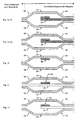
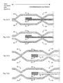
- Fig. 1a . 1d to 1f embodiments of a flat gasket according to the invention are shown schematically in cross section. Between the top and bottom functional layers 10 and 20, a stopper 30 and a stopper functional layer is respectively introduced. According to the type "bead next to stopper" is a bead 40 and 45, the stopper 30 with respect to the sealing function against an interior or passage, which is comprised of two components to be sealed against each other, downstream or downstream.
- a downstream half bead 40 is exemplified, while in the Fig. 1e and 1f in each case a downstream full bead 45 is shown.
- FIG. 1a, 1d to 1f respectively upstream beads 50 and 55 according to embodiments of the present invention, wherein in Fig. 1a a half bead 50 is illustrated as an upstream bead and in FIG Fig. 1f an upstream full bead 55 is illustrated.
- FIG. 1a to 1f different stoppers shown schematically.
- folded or crimped stopper function layers 30 are shown in the non-inventive Fig. 1b a on the deck function layer 10 (alternatively on the bottom function layer 20, not shown) mounted stopper 30, in the non-inventive Fig. 1c an inserted between the top and bottom functional position additional functional layer 35, which is substantially flush with the top or bottom functional position 10, 20 with respect to the inner space or the passage and on which a stopper 30 is applied and in the inventive Fig. 1f an inserted between the top and bottom functional position additional functional layer 35 with a by example, on / welding on / soldering / attached stopper 30 such as a stopper ring 30th
- stopper function positions shown schematically in the figures and the deck and floor function position shown schematically in the figures can be combined as desired.
- a plurality of stopper functional layers and one or more further functional layers such as distance function layers, coating function layers (not shown in the figures) but also further functional layers can be provided with one or more beads, with other functional layers also above and / or below the deck - or soil functional position, ie not only between these, can be arranged.
- several beads can be provided upstream and / or downstream.
- the top and bottom functional layers 10, 20 may be substantially symmetrical / congruent, as schematically illustrated, but the top and bottom functional layers 10, 20 may also include one or more different types of sip, one or more different positions of the sipes, and / or have a different number of beads.
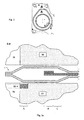
- Fig. 2 shows a schematic plan view of a flat gasket according to an embodiment of the present invention.
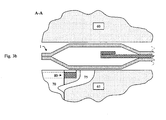
- Fig. 3a and 3b show cuts through the in Fig. 2 illustrated flat gasket according to the invention in the Fig. 2 designated sections.
- Fig. 3a and 3b show a two-part component with cover component 60 and bottom component 65 (such as, for example, an engine block 65 and a cylinder head 60) with a flat gasket 1 according to an embodiment, which is arranged between the components 60 and 65 to be sealed.
- cover component 60 and bottom component 65 such as, for example, an engine block 65 and a cylinder head 60
- flat gasket 1 according to an embodiment, which is arranged between the components 60 and 65 to be sealed.
- a gas opening 70 illustrates the opening to be sealed, the interior to be sealed or passage.
- a leakage of gases or media in the opening, the interior or the passage through a gap which is formed by cover and bottom components 60 and 65 is at least substantially prevented by the arranged and compressed in the intermediate space flat gasket 1.
- an opening such as a gas flow opening 65 may be provided.
- an insert member 80 is provided.
- the insert member 80 may be, for example, a liner ring, but may alternatively have other shapes including the aperture, interior, or passage. That is, the insert member 80 may alternatively be, for example, elliptical, but have substantially any shape encompassing the aperture, interior, or passage.
- the insert member 80 may include a protrusion or shelter with respect to the respective sealing surface, or may be substantially aligned with the respective sealing surface.
- the supernatant of the insert member 80 may be circumferentially variable, i. the insert member 80 may be partially a shelter, partially a supernatant and partially aligned, or any combination thereof be designed.
- the insert member may have a circumferential variable cross-section.
- the insert member 80 may be provided on one of the components 60 and 65 or in both components 60 and 65.
- the insert member 80 may be made of the same material as the members 60 and 65 or another, preferably a metal such as a spring steel.
- the upstream beads 50, 55 may have properties different from those of the downstream beads 40, 45.
- the upstream beads 50, 55 or the beads 50, 55 that come in contact with the insert component 80 may have softer bead characteristics.
- the insert member 80 may have a shelter / supernatant with respect to the respective sealing surface, the compression of the upstream bead (s) and thus their sealing effect (s) is made possible to adapt specifically to a desired requirement profile.
- the stopper of the flat gasket 1 according to the invention is no longer the first sealing stage against media / gases in the opening to be sealed, the interior or the passage. Rather, now realize the upstream beads 50, 55, the first Abdichtcut A.
- the pressure-dependent sealing function of the upstream beads 50, 55 can by means of Insertion member 80 and its shelter / supernatant with respect to the respective sealing surface can be adjusted. Subsequently comes now as the second sealing step B caused by the stopper surface pressure effect. If the stopper then loses contact as the interior pressure increases, the beads downstream of the stopper assume the sealing function as the third sealing stage C.
- the prestressing of the flat gasket between the sealing surfaces of the components to be sealed means that the downstream beads are not used, for example at low to medium internal pressure ,
- the gas flow opening 75 in the illustrated embodiment forms a channel from the opening 70, the interior or the passage.
- the channel of the gas flow opening 75 terminates in a region of the respective sealing surface of the component 65, in which the flat gasket 1 according to the invention is arranged.
- the channel of the gas flow opening 75 terminates in a region of the respective sealing surface of the component 65 which, with the flat gasket 1 according to the invention, a (line) sealing region of the upstream beads 50, 55 and the (surface) sealing region of the stopper 35.
- the adjustable projection / Shelter of the insert member 80 can now be the VerpressCHE of the respective, upstream bead 50 and insert member 80 can be adjusted, ie the Abdichtschreib / sealing function by the first beads relative to the respective component 60, 65 with insert member 80 can be adjusted. Accordingly, the upstream bead loses its sealing function at a predetermined pressure, and gas can flow through the channel 75 of the gas flow port.
Description
Die vorliegende Erfindung betrifft eine Flachdichtung, insbesondere für Brennkraftmaschinen wie zum Beispiel eine Zylinderkopfdichtung, eine Dichtung im Bereich der Abgaszuführung bzw. Abgasabführung von Turboladern oder eine Dichtung im Bereich der Abgasrückführung.The present invention relates to a flat gasket, in particular for internal combustion engines, such as a cylinder head gasket, a gasket in the region of the exhaust gas supply or exhaust gas discharge of turbochargers or a gasket in the region of exhaust gas recirculation.
Flachdichtungen wie zum Beispiele Zylinderkopfdichtungen dichten Brennräume, Medium-Durchführungen wie Kühl-, Schmiermittel- und Abgasdurchführungen sowie Schraublöcher ab. Sie sind Kraftvermittler zwischen den zu dichtenden Bauteilen, zum Beispiel Motorblock und Zylinderkopf, und weisen dadurch einen erheblichen Einfluss auf die Kraftverteilung im Gesamtsystem auf. So müssen Zylinderkopfdichtungen beispielsweise gasdicht abschließen und gleichzeitig Motoröl- und Kühlwasserkanäle sicher gegen Flüssigkeitsaustritt abdichten. Eine herkömmliche Flachdichtung ist z.B. aus
Klassische Weichstoff-Flachdichtungen können zum Beispiel aus einem gespleißten Trägerblech bestehen, auf das beidseitig Weichstoffmaterial ausgebracht zum Beispiel durch Walzen ist. Metallische Einfassungen können vorgesehen sein, die Brennräume, Medium-Durchführungen und Schraublöcher abzudichten und schützen das Weichstoffmaterial vor Überhitzung. Eine Imprägnierung der Weichstoffmaterialoberfläche kann ein Quellen durch Kontakt mit den Medien wie zum Beispiel Öl, Wasser, Frostschutzmittel oder andere Flüssigkeiten bzw. Gase verhindern. Sogenannte Viton-Elemente bevorzugt aus Elastomerwerkstoffen können vorgesehen sein, um eine partielle Erhöhung der Flächenpressung in vorbestimmten Bereichen wie z.B. Öldruckbohrungen zu ermöglichen. Durch die Flächenpressung wird der Werkstoff so verformt, dass er sich an die abzudichtenden Flächen anpasst. Für die Abdichtung sind vergleichsweise hohe Einspannkräfte bei niedrigen Rückfedereigenschaften erforderlich.Classic soft material flat gaskets can, for example, consist of a spliced carrier sheet to which soft material is applied on both sides, for example by rolling. Metallic enclosures may be provided to seal the combustion chambers, fluid passages and screw holes and protect the soft material from overheating. Impregnation of the fabric surface may prevent swelling by contact with the media, such as oil, water, antifreeze, or other liquids or gases. So-called Viton elements, preferably of elastomeric materials, may be provided to provide a partial increase in surface pressure in predetermined areas, e.g. Allow oil pressure holes. Due to the surface pressure, the material is deformed so that it adapts to the surfaces to be sealed. For the sealing comparatively high clamping forces with low springback properties are required.
Werden hohe Anforderungen an die Dichtwirkung von Flachdichtungen gestellt, wie zum Beispiel hohe Drücke, unter dem das anzudichtende Gas bzw. Medium steht, oder hohe Temperaturen, können sogenannte Mehr-Lagen- bzw. Mehr-Lagen-Stahl-Dichtungen (MLS-Dichtungen) eingesetzt werden. Solche Mehr-Lagen-Stahl-Dichtungen bestehen aus zwei oder mehreren Dichtfunktionslagen aus zum Beispiel Feder- oder Kohlenstoffstahlblechen, die zu einer Mehr-Lagen-Stahl-Flachdichtung aufgeschichtet sind. Zur sicheren Gas- und Medienabdichtung erhöhen Sicken an den abzudichtenden Räumen bzw. Durchführungen/Durchtritten die lokale Pressung (Makroabdichtung), vollflächig oder partielle Elastomerbeschichtungen können die Dichtwirkung (Mikroabdichtung) zusätzlich verbessern.If high demands are placed on the sealing effect of flat gaskets, such as high pressures below which the gas or medium to be sealed is, or high temperatures, so-called multi-layer or multi-layer steel gaskets (MLS gaskets) can be used. be used. Such multi-layer steel seals consist of two or more sealing functional layers of, for example, spring or carbon steel sheets stacked into a multi-layer steel flat gasket. For secure gas and media sealing increase beads on the sealed rooms or Feedthroughs / penetrations Local compression (macro-sealing), full-surface or partial elastomer coatings can additionally improve the sealing effect (micro-sealing).
Die vorliegende Erfindung stellt eine verbesserte, hinsichtlich ihrer Dichtfunktion anwendungsbezogen anpassbare Flachdichtung bereit.The present invention provides an improved flat seal which is adaptable in terms of its sealing function.
Die Aufgabe der vorliegenden Erfindung wird durch eine bezüglich der Dichtfunktion der Flachdichtung vorgeschalteten Sicke, insbesondere mindestens eine Halb- oder Vollsicke, gelöst.The object of the present invention is achieved by a bead, in particular at least one half-bead or full bead, which is connected upstream of the sealing function of the flat gasket.
Erfindungsgemäß wird eine Flachdichtung mit einer oder mehreren Stopperfunktionslagen gemäß Anspruch 1 bereitgestellt, die insbesondere zur Verwendung mit Verbrennungsmotoren als Zylinderkopfdichtung, im Bereich der Abgaszuführung oder Abgasabführung von Turboladern oder im Bereich der Abgasrückführungen vorgesehen ist. Die Flachdichtung weist bezüglich ihrer Abdichtfunktion hinsichtlich mindestens eines Stoppers der einen oder mehreren Stopperfunktionslagen eine oder mehrere vorgeschaltete Sicken auf. Bevorzugt sind Deck- und Bodenfunktionslage symmetrische ausgebildet.According to the invention, a flat gasket with one or more stopper functional layers according to
Erfindungsgemäß weist die Flachdichtung bezüglich ihrer Dichtfunktion hinsichtlich des Stoppers eine oder mehrere nachgeschaltete Sicken auf.According to the invention, the flat gasket with respect to its sealing function with respect to the stopper on one or more downstream beads.
Gemäß einer Ausführungsform ist die Flachdichtung eine mehrlagige Flachdichtung. Bevorzugt ist die Flachdichtung eine Mehr-Lagen-Stahl-Flachdichtung (MLS-Flachdichtung).According to one embodiment, the flat gasket is a multi-layer gasket. Preferably, the gasket is a multi-layer steel gasket (MLS gasket).
Gemäß einer Ausführungsform dichtet mindestens eine der vorgeschalteten Sicken (50, 55) gegenüber mindestens einem Einlegebauteil (80), das in mindestens einer Dichtoberfläche eines zumindest zweiteiligen zu dichtenden Bauteils (60, 65) vorgesehen ist, ab und die Abdichtfunktion der vorgeschalteten Sicke (50, 55) wird durch Vepressen der vorgeschalteten Sicke (50, 55) mit einer Oberfläche des Einlegebauteil (80) erhalten.According to one embodiment, at least one of the upstream corrugations (50, 55) seals against at least one insert component (80) which is provided in at least one sealing surface of an at least two-part component to be sealed (60, 65) and the sealing function of the upstream corrugation (50 , 55) is obtained by compressing the upstream bead (50, 55) with a surface of the insert member (80).
Gemäß einer Ausführungsform weist das Einlegebauteil (80) einen variablen oder konstanten Überstand oder Unterstand oder eine Kombination davon bezüglich der respektiven Dichtoberfläche eines Bauteils des zweiteiligen Bauteils (60, 65) auf.According to one embodiment, the insert member (80) has a variable or constant overhang or shed or a combination thereof with respect to the respective sealing surface of a component of the two-piece component (60, 65).
Gemäß einer Ausführungsform sind die Sicken Vollsicken und/oder Halbsicken.According to one embodiment, the beads are full beads and / or half beads.
Gemäß einer Ausführungsform weist mindestens eines der Bauteile des zweiteiligen Bauteils einen Kanal auf, der in einem Bereich der Dichtoberfläche des respektiven Bauteiles endet, Der Bereich in dem der Kanal endet korrespondiert mit einem Bereich bezüglich der Flachdichtung zwischen dem Dichtbereich der vorgeschalteten Sicke und dem Dichtbereich des Stoppers.According to an embodiment, at least one of the components of the two-part component has a channel which terminates in a region of the sealing surface of the respective component. The region in which the channel ends corresponds to a region with respect to the flat seal between the sealing region of the upstream bead and the sealing region of the Stoppers.
Weitere Vorteile und Merkmale der vorliegenden Erfindung werden aus der folgenden Beschreibung von Ausführungsformen der Erfindung ersichtlich, in der auf die angefügten Zeichnungen Bezug genommen wird, in denen
- Fig. 1a und 1d bis 1f
- erfindungsgemäße Ausführungsformen einer Flachdichtung im Querschnitt darstellt;
- Fig. 1b und 1c
- nicht erfindungsgemäße Ausführungsformen darstellen;
- Fig. 2
- eine bevorzugte erfindungsgemäße Ausführungsform einer Flachdichtung in Aufsicht darstellt; und
- Fig. 3a und 3b
- Querschnitte durch ein zweiteiliges Bauteil mit einer Flachdichtung gemäß einer erfindungsgemäßen Ausführungsform.
- Fig. 1a and 1d to 1f
- embodiments of a flat gasket according to the invention in cross-section;
- Fig. 1b and 1c
- not embodiments of the invention represent;
- Fig. 2
- a preferred embodiment of a flat gasket according to the invention in plan view; and
- Fig. 3a and 3b
- Cross sections through a two-part component with a flat gasket according to an embodiment of the invention.
Gleiche oder ähnliche Bezugszeichen bezeichnen gleiche oder ähnliche Elemente.Like or similar reference characters designate the same or similar elements.
Nachfolgend wird die Erfindung mit Bezugnahme auf Zylinderkopfdichtungen, insbesondere Mehr-Lagen-Stahl-Zylinderkopfdichtung (MLS-Zylinderkopfdichtung) dargelegt. Dem Fachmann wird zweifelsohne erkennen, dass die Lehre der Erfindung nicht auf das Gebiet der Mehr-Lagen-Stahl-Zylinderkopfdichtung für Brennkraftmaschinen eingeschränkt anwendbar ist. Vielmehr lässt sich die Lehre der Erfindung auf weitere Flachdichtungen, die insbesondere auf dem Gebiet der Brennkraftmaschinen Verwendung finden, wie zum Beispiel Dichtungen in der Abgaszuführung bzw. Abgasabführung von Turboladern oder im Bereich der Abgasrückführung anwenden. Weiterhin wird der Fachmann ebenso unmittelbar verstehen, dass die Lehre der Erfindung nicht auf Mehr-Lagen-Stahl-Flachdichtungen (MLS-Flachdichtungen) beschränkt ist sondern ebenso Anwendung auf dem Gebiet der mehrlagigen Flachdichtungen finden kann. MLS-Flachdichtungen bzw. MLS-Zylinderkopfdichtungen sind hierbei als jeweilige Spezialfälle von mehrlagigen Flachdichtungen anzusehen.The invention will now be described with reference to cylinder head gaskets, in particular multi-layer steel cylinder head gaskets (MLS cylinder head gaskets). It will no doubt be appreciated by those skilled in the art that the teachings of the invention are not limited to the field of multi-layer steel cylinder head gaskets for internal combustion engines. On the contrary, the teaching of the invention can be applied to further flat gaskets which are used in particular in the field of internal combustion engines, for example gaskets in the exhaust gas supply or exhaust gas removal of turbochargers or in the area of exhaust gas recirculation. Furthermore, the skilled person will also immediately understand that the teaching of the invention is not limited to multi-layer steel flat gaskets (MLS gaskets) but can also find application in the field of multilayer flat gaskets. MLS flat gaskets or MLS cylinder head gaskets are to be regarded as respective special cases of multilayer gaskets.
Zylinderkopfdichtungen sind Flachdichtungen, die unter technologisch anspruchsvollen Bedingungen, Brennräume, Kühl- und Schmiermitteldurchführungen sowie Befestigungsdurchführungen (insbesondere Schraubendurchführungen) gegeneinander andichten. Die Zylinderkopfdichtung ist hierbei Kraftvermittler zwischen dem Zylinderkopf und dem Motorblock und weist dadurch einen erheblichen Einfluss auf die Kraftverteilung im Gesamtsystem Motor. Je nach Anforderungen, die durch die Betriebsbedingungen des zu dichtenden Motors definiert werden, bestehen Zylinderkopfdichten mit einer oder mehreren Lagen, insbesondere Stahllagen. Gegenwärtig werden bis zu fünf Lagen verwendet, dies ist jedoch nicht als Einschränkung zu verstehen. Der Grundaufbau einer mehrlagigen Flachdichtung, wie eine Zylinderkopfdichtung, umfasst eine Deck- und Bodenlage als Funktionslagen.Cylinder head gaskets are flat gaskets that seal against each other under technologically demanding conditions, combustion chambers, coolant and lubricant feedthroughs as well as fastening bushings (in particular screw lead-throughs). The cylinder head gasket here is force mediator between the cylinder head and the engine block and thus has a significant influence on the power distribution in the engine as a whole. Depending on the requirements, which are defined by the operating conditions of the engine to be sealed, there are cylinder head densities with one or more layers, in particular steel layers. Currently, up to five layers are used, but this is not meant to be limiting. The basic structure of a multi-layer gasket, such as a cylinder head gasket, includes a top and bottom layer as functional layers.
Zumindest eine dieser Funktionslagen, bevorzugt beide, ist gesickt, bevorzugt sind die Deck- bzw. Bodenfunktionslagen kongruent gesickt, und bestehen vorzugsweise aus Stahl wie zum Beispiel Federstahl oder federharten Edelstählen. Die Sicken werden durch zum Beispiel Prägen eingebracht. Um Dichtwirkung der Sicken sicherzustellen, muss die Deck- und Bodenfunktionslage im Bereich der Sicke eine für die vorgesehene Anwendung geeignete Federeigenschaft und Zugfestigkeit aufweisen. Definierte Sicken erzeugen durch die federelastischen Eigenschaften der Deck- und Bodenfunktionslage Linienpressungen im Bereich der Dichtoberflächen der zu dichtenden Bauteile, um zum Beispiel Brennräume oder Mediendurchtritte wie Abgas-, Kühl- oder Schmiermitteldurchtritte abzudichten. Durch die elastische Eigenschaft der Deck- bzw. Bodenfunktionslage, die bevorzugt aus Federstahlblech hergestellt sind, bilden sich bei einer Vollsicke vier Einzellinien mit hoher Linienpressung gegenüber den Dichtoberflächen der zu dichtenden Bauteile aus, während bei einer Halbsicke aufgrund der Eigenschaft der Deck- bzw. Bodenfunktionslage zwei Einzellinien mit hoher Linienpressung ausgebildet werden. Vollsicken können beispielsweise dynamische Dichtspaltbewegungen ausgleichen und kommen zum Beispiel bei Zylinderkopfdichtungen zur Abdichtung von Brennräumen zur Verwendung. Halbsicken erzeugen geringere Linienpressungen als Vollsicken und werden bei Zylinderkopfdichtungen bevorzugt zur Abdichtung gegen Gas und Medien wie zum Beispiel Kühlwasser und Öl und der Schraubenlöcher verwendet und dichten umlaufend die äußere Dichtungskontur. Durch die geringere Linienpressung der Halbsicken einer Zylinderkopfdichtung bleibt die Hauptpressung der Vollsicken an den Brennräumen im Wesentlichen erhalten.At least one of these functional layers, preferably both, is beaded, preferably the cover or bottom functional layers are congruently beaded, and are preferably made of steel, such as spring steel or spring-hard stainless steels. The beads are introduced by embossing, for example. In order to ensure the sealing effect of the beads, the cover and bottom functional position in the region of the bead must have a suitable spring property and tensile strength for the intended application. Defined beads generate line pressures in the region of the sealing surfaces of the components to be sealed due to the elastic properties of the cover and bottom functional position, for example to seal combustion chambers or media passages such as exhaust gas, coolant or lubricant passages. Due to the elastic property of the cover or bottom functional layer, which are preferably made of spring steel sheet, four individual lines are formed in a full bead with high line pressure compared to the sealing surfaces of the components to be sealed, while at a half bead due to the property of the deck or floor function position two individual lines are formed with high line pressure. For example, full corrugations can compensate for dynamic sealing gap movements and are used, for example, in cylinder head gaskets for sealing combustion chambers. Semi-beads produce lower line pressures than full corrugations and are preferably used in cylinder head gaskets for sealing against gas and media such as cooling water and oil and screw holes, and circumferentially seal the outer seal contour. Due to the lower line pressure of the half beads of a cylinder head gasket, the main compression of the full corrugations on the combustion chambers is essentially retained.
Eine Vollsicke kann typischerweise durch eine Sickentiefe Y, einen Schenkelwinkel X und eine Kopfbreite V charakterisiert werden. Eine Halbsicke kann typischerweise durch eine Sickentiefe Y und einen Schenkelwinkel X charakterisiert werden. Neben der Geometrie habe Qualität, Dicke und Herstellungsprozess wesentlichen Einfluss auf die Eigenschaften der Sicken. Durch diese Faktoren lassen sich eine Vielzahl unterschiedlicher Sicken mit definierten Belastungs- und Rückfederungseigenschaften herstellen, die sich in ihrer Charakteristik bzw. Kraftaufnahme deutlich unterscheiden. So können weichere oder härtere Sicken realisiert werden. Zum Beispiel sind Vollsicken mit kleinem Schenkelwinkel X sind weicher und haben eine flachere Federkennlinie und eine höhere Dauerstandfestigkeit.A full bead may typically be characterized by a bead depth Y, a leg angle X, and a head width V. A half bead can typically be characterized by a bead depth Y and a leg angle X. Next to the geometry quality, thickness and manufacturing process have a significant influence on the properties of the beads. These factors make it possible to produce a large number of different beads with defined load and springback properties, which differ significantly in terms of their characteristic or force absorption. So softer or harder beads can be realized. For example, small-pitch solid beads X are softer and have a flatter spring characteristic and higher creep rupture strength.
Neben Sicken, die eine Linienpressungen im Bereich der Dichtoberflächen der zu dichtenden Bauteile ausbilden, können ferner sogenannte Stopper vorgesehen sein, durch die eine erhöhte Flächenpressung im Bereich der Dichtoberflächen der zu dichtenden Bauteile erzielt werden kann. Insbesondere bei MLS-Zylinderkopfdichtungen sind Stopper im Bereich des Brennraums vorgesehen. Die sogenannten Stopper sind bevorzugt als aktive Funktionslage einer mehrlagigen Flachdichtung, die beispielsweise zwischen der Deck- und Bodenfunktionslage angeordnet ist, vorgesehen, um durch eine Überhöhung die Flächenpressung der Flachdichtung mit den Dichtoberflächen der zu dichtenden Bauteile zu erhöhen und ein Flachdrücken der Sicken zu verhindern, da beim Flachdrücken die Gefahr besteht, dass die Deck- und/oder Bodenfunktionslage im Bereich der Sicke die erforderliche Federeigenschaft bzw. Zugfestigkeit verlieren können, oder es zu einer Verringerung des zu dichtenden Querschnitts kommen kann. Beim Einbau einer Flachdichtung mit Stopper-Funktionsschicht wie zum Beispiel einer MLS-Zylinderkopfdichtung werden Sicken bis auf Stopper-Höhe oder bis zum Gleichgewicht der Sickenkraftaufnahme und Einspannkräften der Flachdichtung (z.B. den Schraubenkräften) verpresst. Das heißt, dass ein Stopper im Wesentlichen die Einbauhöhe der Sicken (Vollsicken) vorgibt und die Funktion des Stoppers hierbei die Begrenzung der Sickenverformung ist, indem der Grad der Verpressung der Sicken bestimmt wird Eine typische Höhe ausgeführter Stopper reicht von einigen 1/100 mm bis etwa 0,15 mm.In addition to corrugations, which form a line pressure in the region of the sealing surfaces of the components to be sealed, so-called stoppers can also be provided by which an increased surface pressure in the region of the sealing surfaces of the components to be sealed can be achieved. Especially with MLS cylinder head gaskets, stoppers are provided in the area of the combustion chamber. The so-called stoppers are preferably provided as an active functional layer of a multilayer flat gasket, which is arranged, for example, between the top and bottom functional layer, in order to increase the surface pressure of the flat gasket with the sealing surfaces of the components to be sealed and prevent flattening of the corrugations by an elevation. since when flattening there is a risk that the cover and / or floor operating position in the region of the bead can lose the required spring property or tensile strength, or it can lead to a reduction in the cross-section to be sealed. When installing a gasket with a stopper functional layer, such as an MLS cylinder head gasket, beads are crimped to stopper height or to the equilibrium of the sip force and clamping forces of the gasket (e.g., bolt forces). That is, a stopper essentially dictates the installation height of the beads (full corrugations) and the function of the stopper is thereby the limitation of the bead deformation by determining the degree of crimping of the beads. A typical height of executed stoppers ranges from a few 1/100 mm about 0.15 mm.
Stopper-Konstruktionen können als α-Stopper, Ω-Stopper, symmetrische U-Sicke mit einer harten Beschichtung, Wellen- oder Trapez-Stopper in eine aktive Funktionslage integriert bzw. als zusätzliche Funktionslage zwischen den aktiven Funktionslagen ergänzt werden. Ferner können in einer mehrlagigen Flachdichtung auch mehrere derartige StopperFunktionslagen vorgesehen sein. Gleichzeitig ist durch Stopper-Konstruktionen eine bessere topografische Anpassung an die angrenzenden Bauteile möglich. Ferner können Stopper wie folgt unterscheiden werden:
- starrer Stopper (z.B. gefalztes bzw. gebördeltes Stopperfunktionslage, auf/eingeschweißter bzw. -gelöteter Stopperfunktionslage wie zum Beispiel ein Stopperring etc.);
- plastischer Stopper (Anpassung des Höhenprofils der Flachdichtung);
- höhenprofilierter oder topographischer Stopper (angepasstes Höhenprofil bei der Herstellung), z.B. aufgesinterter Stopper, gezielte Reduzierung des Trägers in Bereichen hoher Bauteilsteifigkeit etc.; und
- besondere Stopper-Geometrie. z.B. Wellenstopper, Breitstopper.
- rigid stopper (eg folded or crimped stopper functional position, on / welded-in or soldered stopper functional position, such as a stopper ring, etc.);
- plastic stopper (adaptation of the height profile of the flat gasket);
- height-profiled or topographical stopper (adapted height profile during production), eg sintered stopper, targeted reduction of the carrier in areas of high component stiffness, etc .; and
- special stopper geometry. eg wave stopper, wide stopper.
Für MLS-Flachdichtungen kann ein Stopper aus verschiedenen Stahlqualitäten von beispielsweise Kohlenstoffstahl bis zu Edelstahl ausgewählt werdenFor MLS flat gaskets, a stopper can be selected from various grades of steel, from carbon steel to stainless steel, for example
In mehrlagigen Flachdichtungen, wie MLS-Flachdichtungen, können weitere Funktionslagen vorsehen, so zum Beispiel eine oder mehrere weitere gesickte Funktionslagen, Distanzfunktionslagen und/oder Elastomerfunktionslagen.In multilayer flat gaskets, such as MLS flat gaskets, further functional layers can provide, for example one or more further bonded functional layers, spacer functional layers and / or elastomeric functional layers.
Über ein Distanzfunktionslagen, die als Konstruktionselement und variables Element zur Anpassung der Einbaudicke dienen, kann durch entsprechende Gestaltung eine elastisch/plastische Anpassung an die zu Druckverhältnisse in dem zu dichtenden Raum bzw. Durchtritt erzielt werden.By means of a spacer function layer, which serves as a construction element and a variable element for adapting the installation thickness, an elastic / plastic adaptation to the pressure conditions in the space or passage to be sealed can be achieved by appropriate design.
Elastomerfunktionslagen können bevorzugt als ein- oder beidseitige Elastomerbeschichtung auf aktiven Funktionslagen, insbesondere der Deck- und Bodenfunktionslagen, aufgebracht werden und stellen die sogenannte Mikro-Abdichtung d. h. die Abdichtung gegen die Oberflächenrauheit der Dichtoberflächen der zu dichtenden Bauteile bzw. zwischen den Funktionslagen einer mehrlagigen Flachdichtung sicher. Die sogenannte Makro-Abdichtung übernehmen die in Funktionslagen eingeprägten Sicken bzw. der/die mittels Stopperfunktionslagen bereitgestellten Stopper. Durch kontrollierten Anpressdruck füllt und gleicht eine derartige Bcschichtung vorhandene Rauigkeiten, Kratzer und Porositäten aus. Die Beschichtung der Oberflächen verfügt über entsprechende Gleiteigenschaften, um sogenannten "Fretting"-Marken durch Mikrobewegungen unter hoher Flächenpressung vorzubeugen. Die Funktionslagen können ganzflächig oder auch nur partiell, einlagig oder mehrlagig beschichtet sein bzw. eine oder mehrere spezielle Beschichtungen zum Beispiel in vorbestimmten Bereichen haben, die zum Beispiel auf die extremen Anforderungen (hohe Temperaturen, große Gleitbewegungen) abgestimmt ist. Durch Beschichtungen kann ein definiertes Fließverhalten vorgegeben werden. Als Elastomerbeschichtung kann zum Beispiel ein (hochtemperaturbeständiges) Fluor-Polymer dienen.Elastomeric functional layers may preferably be applied as single or double-sided elastomeric coating on active functional layers, in particular the cover and bottom functional layers, and provide the so-called micro-sealing d. H. the seal against the surface roughness of the sealing surfaces of the components to be sealed or between the functional layers of a multilayer flat gasket safely. The so-called macro-sealing take over the embossed in functional layers beads or / the stoppers provided by Stopperfunktionslagen stopper. By means of controlled contact pressure, such a coating fills and compensates for existing roughness, scratches and porosities. The coating of the surfaces has corresponding sliding properties in order to prevent so-called "fretting" marks due to micro movements under high surface pressure. The functional layers can be coated over the whole area or even only partially, in one or more layers or have one or more special coatings, for example in predetermined areas, which are adapted to the extreme requirements (high temperatures, large sliding movements), for example. By coatings, a defined flow behavior can be specified. For example, a (high temperature resistant) fluoropolymer can serve as an elastomer coating.
Die Funktionsweise einer mehrlagigen Flachdichtung mit Stopper-Funktionslage lässt sich in geeigneter Weise am Beispiel einer MLS-Zylinderkopfdichtung mit Stopper darstellen. Die Allgemeingültigkeit und Übertragbarkeit auf mehrlagige Flachdichtungen dieser Darstellung ist unmittelbar zu erkennen.The mode of operation of a multilayer flat gasket with a stopper functional position can be represented in a suitable manner using the example of an MLS cylinder head gasket with a stopper. The Generality and transferability to multilayer flat gaskets of this representation can be seen immediately.
Die konventionelle MLS-Zylinderkopfdichtung entspricht der Bauart "Sicke neben Stopper, d. h. vom Brennraumrand aus betrachtet liegt die Sicke hinter dem Stopper. Sie befindet sich damit im "Kraft-Nebenschluss". Die zur Brennraumabdichtung notwendige Sicke kann jedoch nicht nur neben, sondern auf dem Stopper, einer umlaufenden Stopperbrille, liegen. Dies ist z.B. bei der "Bead-on-Stopper-Technologie" der Fall. Die Sicke liegt dann im "Kraft-Hauptschluss". Vorteilhaft ist die Nutzung der eingeleiteten Schraubenkräfte primär für die Gasabdichtung. Es kann auch eine zusätzliche zweite Dichtlinie durch eine nachgeschaltete, umlaufende Brennraumhalbsicke dargestellt werden. Der Stopper gibt bei diesem Konstruktionsprinzip allerdings nicht mehr die Einbauhöhe der Brennraumsicke vor.The conventional MLS cylinder head gasket corresponds to the design "beading next to the stopper, ie viewed from the combustion chamber edge, the bead is behind the stopper and is thus in the" power shunt. "However, the bead necessary for combustion chamber sealing can not only be next to but also on the side This is the case, for example, with the "bead-on-stopper technology." The bead then lies in the "force main circuit." Advantageously, the use of the introduced bolt forces is primarily for the gas seal However, an additional second sealing line can be represented by a downstream, circumferential combustion chamber half bead, but the stopper no longer specifies the installation height of the combustion chamber bead in this design principle.
Der Stopper einer MLS-Zylinderkopfdichtung ist die erste Abdichtstufe gegen Verbrennungsgase im Brennraum. Durch die Vorspannung der Flachdichtung zwischen den Dichtoberflächen der zu dichtenden Bauteile kommen die Sicken bei niedrigen bis mittleren Innenraumdrücken nicht zum Einsatz. Die Abdichtung erfolgt ausschließlich dadurch, dass die Dichtoberflächen der zu dichtenden Bauteile über den Bereich des Stoppers vorgespannt sind. Wenn der Stopper dann bei steigendem Innenraumdruck den Kontakt verliert, übernehmen die bezüglich des Stoppers nachgeschalteten Sicken die Dichtfunktion.The stopper of an MLS cylinder head gasket is the first sealing stage against combustion gases in the combustion chamber. Due to the prestressing of the flat gasket between the sealing surfaces of the components to be sealed, the beads are not used at low to medium internal pressure. The sealing takes place exclusively in that the sealing surfaces of the components to be sealed are biased over the area of the stopper. If the stopper then loses contact with increasing interior pressure, take over the downstream of the stopper beads the sealing function.
In
In den
Ferner zeigen die
Weiterhin sind in den
Es wird verstanden, dass die in den Figuren schematisch dargestellten Stopperfunktionslagen und die in den Figuren schematisch dargestellten Deck- und Bodenfunktionslage beliebig kombiniert werden können. Ferner können wie vorstehend dargelegt mehrere Stopperfunktionslagen sowie eine oder mehrere weitere Funktionslagen wie zum Beispiele Distanzfunktionslagen, Beschichtungsfunktionslagen (in den Figuren nicht gezeigt) aber auch weitere Funktionslagen mit einer oder mehreren Sicken vorgesehen sein, wobei weitere Funktionslagen auch ober- und/oder unterhalb der Deck- bzw. Bodenfunktionslage, d.h. nicht nur zwischen diesen, angeordnet sein können. Weiterhin können auch mehrere Sicken (Voll- und/oder Halbsicken) vor- und/oder nachgeschaltet vorgesehen sein. Die Deck- und Bodenfunktionslagen 10, 20 können wie schematisch illustriert im Wesentlichen (spiegel-) symmetrisch/kongruent ausgebildet sein, jedoch können die Deck- und Bodenfunktionslagen 10, 20 auch ein oder mehrere verschiedene Sickentypen, eine oder mehrere verschiedene Positionen der Sicken, und/oder eine unterschiedliche Anzahl von Sicken aufweisen.It is understood that the stopper function positions shown schematically in the figures and the deck and floor function position shown schematically in the figures can be combined as desired. Furthermore, as set out above, a plurality of stopper functional layers and one or more further functional layers such as distance function layers, coating function layers (not shown in the figures) but also further functional layers can be provided with one or more beads, with other functional layers also above and / or below the deck - or soil functional position, ie not only between these, can be arranged. Furthermore, several beads (full and / or half beads) can be provided upstream and / or downstream. The top and bottom
Eine Gasöffnung 70 illustriert die zu dichtende Öffnung, den zu dichtenden Innenraum bzw. Durchtritt. Ein Austritt von Gasen bzw. Medien in der Öffnung, dem Innenraum bzw. dem Durchtritt durch einen Zwischenraum, der durch Deckel- und Bodenbauteile 60 und 65 gebildet wird, wird durch die in dem Zwischenraum angeordnete und verpresste Flachdichtung 1 zumindest im Wesentlichen verhindert. Ferner kann in einem der Bauteile 60, 65 zusätzlich eine Öffnung wie zum Beispiel eine Gasstromöffnung 65 vorgesehen sein.A
Weiterhin ist in den
Das Einlegebauteil 80 kann einen Überstand oder Unterstand bezüglich der respektiven Dichtoberfläche aufweisen oder im Wesentlichen mit der respektiven Dichtoberfläche fluchten. Der Überstand bzw. Unterstand des Einlegebauteils 80 kann umfänglich variable sein, d.h. das Einlegebauteil 80 kann bereichsweise einen Unterstand, bereichsweise einen Überstand und bereichsweise fluchtend, oder eine beliebige Kombination davon ausgelegt sein. Das Einlegebauteil kann einen umfangsbezüglichen variablen Querschnitt aufweisen. Das Einlegebauteil 80 kann ein einem der Bauteile 60 und 65 oder in beiden Bauteilen 60 und 65 vorgesehen sein. Das Einlegebauteil 80 kann aus dem gleichen Material wie die Bauteile 60 und 65 gefertigt sein oder aus einem anderen, bevorzugt einem Metall wie zum Beispiel einem Federstahl.The
Die vorgeschalteten Sicken 50, 55 können Eigenschaften aufweisen, die von den der nachgeschalteten Sicken 40, 45 verschieden sind. So können zum Beispiel die vorgeschalteten Sicken 50, 55 bzw. die mit dem Einlegebauteil 80 Kontakt eingehende Sicke 50, 55 weichere Sickenkennlinien aufweisen. Zusammen mit der Möglichkeit, dass das das Einlegebauteil 80 einen Unterstand/Überstand bezüglich der respektiven Dichtoberfläche aufweisen kann, wird ermöglich die Verpressung der vorgeschalteten Sicke(n) und damit deren Dichtwirkung(en) spezifisch an ein gewünschtes Anforderungsprofil anzupassen.The
Der Stopper der erfindungsgemäßen Flachdichtung 1 ist nun nicht mehr die erste Abdichtstufe gegen Medien/Gase in der zu dichtenden Öffnung, dem Innenraum bzw. dem Durchtritt. Vielmehr realisieren nun die vorgeschalteten Sicken 50, 55 die erste Abdichtstufe A. Die druckabhängige Abdichtfunktion der vorgeschalteten Sicken 50, 55 kann mittels des Einlegebauteils 80 bzw. dessen Unterstand/Überstand bezüglich der respektiven Dichtoberfläche eingestellt werden. Nachfolgend kommt als nun zweite Abdichtstufe B die durch den Stopper bewirkte Flächenpressung zur Wirkung. Wenn der Stopper dann bei steigendem Innenraumdruck den Kontakt verliert, übernehmen die bezüglich des Stoppers nachgeschalteten Sicken die Dichtfunktion als dritte Abdichtstufe C. Durch die Vorspannung der Flachdichtung zwischen den Dichtoberflächen der zu dichtenden Bauteile kommen die nachgeschalteten Sicken z.B. bei niedrigen bis mittleren Innenraumdrücken nicht zum Einsatz.The stopper of the
Wie in
Claims (7)
- A flat gasket (1) with at least one beaded layer (10, 20) and one or more stopper function layers (30, 35), wherein the flat gasket (1) includes at least one peripheral stopper (30) in the stopper function layer around an opening therein to be sealed, and wherein at least one first peripheral bead (50, 55) is arranged upstream relative to the sealing function in at least one beaded layer on a side of the stopper that lies in the direction of the opening to be sealed, wherein at least one second peripheral bead (40, 45) is arranged downstream on the side of the stopper that faces away from the opening to be sealed, characterized in that the stopper function layer ends before the first bead in the direction of the opening to be sealed.
- The flat gasket according to claim 1, wherein the flat gasket (1) is a flat multilayer gasket, preferably a multilayer steel gasket.
- The flat gasket according to any previous claim with a component to be sealed having at least two parts, wherein the at least one of the upstream peripheral beads (50, 55) seals relative to at least one insert component provided in at least one sealing surface of the at least two-part component (60,65) to be sealed, and wherein the sealing function of the at least one upstream bead (50,55) is realized by compressing the at least one upstream bead (50,55) with a surface of the insert component (80).
- The flat gasket according to claim 2 with a component to be sealed having at least two parts, wherein a insert component (80) has a variable or constant protrusion or recession or a combination thereof relative to the respective sealing surface of one part of the two-part component 60,65).
- The flat gasket according to any previous claim, wherein the upstream beads are full beads.
- The flat gasket according to any of claims 1 to 4, wherein the upstream beads are half beads.
- The flat gasket according to any previous claim with a component to be sealed having at least two parts, wherein at least one of the parts of the two-part component (60,65) includes a channel (75) that ends in an area of the sealing surface of the respective component, wherein the area in which the channel ends corresponds to an area of the flat gasket (1) between the sealing area of the upstream bead (50,55) and the sealing area of the stopper (30).
Applications Claiming Priority (2)
| Application Number | Priority Date | Filing Date | Title |
|---|---|---|---|
| DE102009008791A DE102009008791A1 (en) | 2009-02-13 | 2009-02-13 | Flat seals with additional sealing element |
| PCT/EP2009/007677 WO2010091705A1 (en) | 2009-02-13 | 2009-10-27 | Gaskets having additional sealing element |
Publications (2)
| Publication Number | Publication Date |
|---|---|
| EP2396575A1 EP2396575A1 (en) | 2011-12-21 |
| EP2396575B1 true EP2396575B1 (en) | 2013-08-14 |
Family
ID=41682711
Family Applications (1)
| Application Number | Title | Priority Date | Filing Date |
|---|---|---|---|
| EP09748033.9A Not-in-force EP2396575B1 (en) | 2009-02-13 | 2009-10-27 | Gaskets having additional sealing element |
Country Status (5)
| Country | Link |
|---|---|
| US (1) | US20110298186A1 (en) |
| EP (1) | EP2396575B1 (en) |
| CN (1) | CN102272494B (en) |
| DE (1) | DE102009008791A1 (en) |
| WO (1) | WO2010091705A1 (en) |
Families Citing this family (3)
| Publication number | Priority date | Publication date | Assignee | Title |
|---|---|---|---|---|
| DE102010001660A1 (en) * | 2010-02-08 | 2011-08-11 | Federal-Mogul Sealing Systems GmbH, 57562 | Metallic seal with non-exhaust resistant insert |
| US9939066B2 (en) * | 2013-03-14 | 2018-04-10 | Federal-Mogul Llc | Elastic sealing member radially inwardly of primary sealing bead |
| US9964068B2 (en) | 2016-02-25 | 2018-05-08 | Ford Global Technologies, Llc | Head gasket for an internal combustion engine |
Family Cites Families (32)
| Publication number | Priority date | Publication date | Assignee | Title |
|---|---|---|---|---|
| US5213345A (en) * | 1986-11-10 | 1993-05-25 | Ishikawa Gasket Co., Ltd. | Steel laminate gasket with wide sealing area |
| FR2621352B1 (en) * | 1987-10-02 | 1990-02-09 | Curty Soc | CYLINDER HEAD GASKET FOR INTERNAL COMBUSTION ENGINE |
| US4896891A (en) * | 1988-05-16 | 1990-01-30 | Ishikawa Gasket Co., Ltd. | Steel laminate gasket with associated beads |
| JP3642588B2 (en) * | 1994-08-04 | 2005-04-27 | 日本ガスケット株式会社 | Metal gasket |
| BR9505567A (en) * | 1995-04-26 | 1997-11-04 | Elringklinger Gmbh | Metal head seal |
| US5979906A (en) * | 1997-02-13 | 1999-11-09 | Farnam/Meillor Sealing Systems Inc. | Multi-layered metal gasket assembly and method of constructing the same |
| US6062572A (en) * | 1997-02-21 | 2000-05-16 | Ishino Gasket Mfg. Co., Ltd. | Metal gasket |
| JPH10259871A (en) * | 1997-03-19 | 1998-09-29 | Nippon Reinz Co Ltd | Cylinder hed gasket |
| DE69806120T2 (en) * | 1998-04-16 | 2005-02-17 | Carl Freudenberg Kg | Metallic flat gasket |
| JP3756713B2 (en) * | 1999-10-20 | 2006-03-15 | 日本リークレス工業株式会社 | Metal gasket for cylinder head |
| JP4718660B2 (en) * | 1999-12-15 | 2011-07-06 | 日本ガスケット株式会社 | Metal gasket |
| DE10021975A1 (en) * | 2000-05-05 | 2001-11-22 | Reinz Dichtungs Gmbh | Cylinder head gasket includes plastic in ring seal stopper elevation, to impart controlled degrees of resilience and plasticity |
| CA2411276C (en) * | 2000-06-15 | 2009-08-18 | Reinz-Dichtungs-Gmbh & Co. Kg | Flat gasket and method for the production thereof |
| FR2814777B1 (en) * | 2000-10-04 | 2003-01-31 | Meillor Sa | CYLINDER HEAD GASKET WITH VARIABLE THICKNESS AND METHOD FOR PRODUCING AND ATTACHING THE SAME |
| DE10050478B4 (en) * | 2000-10-12 | 2009-08-06 | Reinz-Dichtungs-Gmbh | Multi-layer steel gasket |
| DE20021017U1 (en) * | 2000-12-12 | 2001-02-22 | Reinz Dichtungs Gmbh U Co Kg | Cylinder head gasket |
| JP3885959B2 (en) * | 2001-03-07 | 2007-02-28 | 日本メタルガスケット株式会社 | Metal gasket |
| DE10117178B4 (en) * | 2001-04-05 | 2006-11-09 | Elringklinger Ag | Cylinder head gasket |
| DE10310683A1 (en) * | 2003-03-12 | 2004-10-07 | Federal-Mogul Sealing Systems Gmbh | Flat gasket, especially cylinder head gasket |
| JP2004278719A (en) * | 2003-03-17 | 2004-10-07 | Nippon Leakless Corp | Metal gasket for cylinder head |
| US6951338B2 (en) * | 2003-03-21 | 2005-10-04 | Dana Corporation | Cylinder head gasket |
| JP3907618B2 (en) * | 2003-10-30 | 2007-04-18 | 石川ガスケット株式会社 | Metal laminated gasket |
| US20050189724A1 (en) * | 2004-02-26 | 2005-09-01 | Federal-Mogul Corporation | Metal gasket |
| DE102004012905A1 (en) * | 2004-03-17 | 2005-10-13 | Elringklinger Ag | Cylinder head gasket |
| US7374177B2 (en) * | 2004-09-21 | 2008-05-20 | Federal-Mogul World Wide, Inc. | Enhanced multilayer metal gasket |
| JP3949690B2 (en) * | 2005-01-27 | 2007-07-25 | 石川ガスケット株式会社 | Metal laminated gasket |
| DE202005020542U1 (en) * | 2005-02-17 | 2006-03-23 | Elringklinger Ag | Catalysis unit for use in cylinder-head gasket, has substrate with coating containing catalytically active material, where catalysis unit is arranged in combustion chamber area of internal combustion engine |
| DE102005007245A1 (en) * | 2005-02-17 | 2006-05-04 | Elringklinger Ag | Catalysis unit for use in cylinder-head gasket, has substrate with coating containing catalytically active material, where catalysis unit is arranged in combustion chamber area of internal combustion engine |
| JP4137116B2 (en) * | 2005-11-30 | 2008-08-20 | 石川ガスケット株式会社 | Cylinder head gasket |
| JP4309409B2 (en) * | 2006-05-16 | 2009-08-05 | 石川ガスケット株式会社 | Metal gasket |
| JP5034334B2 (en) * | 2006-06-16 | 2012-09-26 | 国産部品工業株式会社 | Metal gasket |
| DE102006034784A1 (en) * | 2006-07-27 | 2008-01-31 | Reinz-Dichtungs-Gmbh | Multi-layer metallic flat gasket, in particular cylinder head gasket |
-
2009
- 2009-02-13 DE DE102009008791A patent/DE102009008791A1/en not_active Withdrawn
- 2009-10-27 EP EP09748033.9A patent/EP2396575B1/en not_active Not-in-force
- 2009-10-27 WO PCT/EP2009/007677 patent/WO2010091705A1/en active Application Filing
- 2009-10-27 CN CN200980156593.8A patent/CN102272494B/en not_active Expired - Fee Related
- 2009-10-27 US US13/201,488 patent/US20110298186A1/en not_active Abandoned
Also Published As
| Publication number | Publication date |
|---|---|
| CN102272494A (en) | 2011-12-07 |
| CN102272494B (en) | 2014-03-12 |
| EP2396575A1 (en) | 2011-12-21 |
| US20110298186A1 (en) | 2011-12-08 |
| DE102009008791A1 (en) | 2010-09-16 |
| WO2010091705A1 (en) | 2010-08-19 |
Similar Documents
| Publication | Publication Date | Title |
|---|---|---|
| DE102008042754B4 (en) | metal seal | |
| DE102006062292B4 (en) | Multi-layer cylinder head gasket with a recessed portion to reduce surface pressure | |
| DE60122436T3 (en) | Cylinder head gasket with various sealing coatings | |
| EP1985897A1 (en) | Flat metal gasket | |
| DE4330780A1 (en) | Multi-layer cylinder head gasket | |
| EP2396575B1 (en) | Gaskets having additional sealing element | |
| DE10244853B4 (en) | Multi-layered cylinder head gasket | |
| DE2849018C2 (en) | Metallic flat gasket, especially cylinder head gasket | |
| DE202013005211U1 (en) | control plate | |
| DE19641491A1 (en) | Automotive gasket spacer layer fabricated from sintered powder | |
| EP1340010B1 (en) | Flat seal for a reciprocating piston engine or machine | |
| EP1992847A1 (en) | Metal flat gasket | |
| DE102010013545A1 (en) | Exhaust line-flat seal for combustion engines, has metallic sealing plate with exhaust-through openings and multiple screw holes attached to exhaust-through openings for passing through of erection screws | |
| DE102016002582A1 (en) | Flat gasket, in particular cylinder head gasket | |
| DE602004009646T2 (en) | Seal with flexible stopper | |
| EP1601892B1 (en) | Flat gasket, in particular cylinder-head gasket | |
| DE102015122797A1 (en) | Cylinder head gasket | |
| WO2015113711A1 (en) | Cylinder-head seal, and a sealing system comprising such a seal | |
| WO2009094964A1 (en) | Flat seal | |
| DE602004000508T2 (en) | A metal laminate gasket | |
| DE602005000474T2 (en) | Cylinder head gasket | |
| EP3380760B1 (en) | Flat seal and sealing assembly containing a flat seal | |
| DE102019203754A1 (en) | metal seal | |
| DE19548574C2 (en) | Metallic cylinder head gasket | |
| DE10123486B4 (en) | Cylinder head gasket |
Legal Events
| Date | Code | Title | Description |
|---|---|---|---|
| PUAI | Public reference made under article 153(3) epc to a published international application that has entered the european phase |
Free format text: ORIGINAL CODE: 0009012 |
|
| 17P | Request for examination filed |
Effective date: 20110601 |
|
| AK | Designated contracting states |
Kind code of ref document: A1 Designated state(s): AT BE BG CH CY CZ DE DK EE ES FI FR GB GR HR HU IE IS IT LI LT LU LV MC MK MT NL NO PL PT RO SE SI SK SM TR |
|
| DAX | Request for extension of the european patent (deleted) | ||
| GRAP | Despatch of communication of intention to grant a patent |
Free format text: ORIGINAL CODE: EPIDOSNIGR1 |
|
| INTG | Intention to grant announced |
Effective date: 20130604 |
|
| GRAS | Grant fee paid |
Free format text: ORIGINAL CODE: EPIDOSNIGR3 |
|
| GRAA | (expected) grant |
Free format text: ORIGINAL CODE: 0009210 |
|
| AK | Designated contracting states |
Kind code of ref document: B1 Designated state(s): AT BE BG CH CY CZ DE DK EE ES FI FR GB GR HR HU IE IS IT LI LT LU LV MC MK MT NL NO PL PT RO SE SI SK SM TR |
|
| REG | Reference to a national code |
Ref country code: GB Ref legal event code: FG4D Free format text: NOT ENGLISH |
|
| REG | Reference to a national code |
Ref country code: AT Ref legal event code: REF Ref document number: 627052 Country of ref document: AT Kind code of ref document: T Effective date: 20130815 Ref country code: CH Ref legal event code: EP |
|
| REG | Reference to a national code |
Ref country code: IE Ref legal event code: FG4D Free format text: LANGUAGE OF EP DOCUMENT: GERMAN |
|
| REG | Reference to a national code |
Ref country code: DE Ref legal event code: R096 Ref document number: 502009007779 Country of ref document: DE Effective date: 20131010 |
|
| REG | Reference to a national code |
Ref country code: NL Ref legal event code: VDEP Effective date: 20130814 |
|
| REG | Reference to a national code |
Ref country code: LT Ref legal event code: MG4D |
|
| PG25 | Lapsed in a contracting state [announced via postgrant information from national office to epo] |
Ref country code: PT Free format text: LAPSE BECAUSE OF FAILURE TO SUBMIT A TRANSLATION OF THE DESCRIPTION OR TO PAY THE FEE WITHIN THE PRESCRIBED TIME-LIMIT Effective date: 20131216 Ref country code: IS Free format text: LAPSE BECAUSE OF FAILURE TO SUBMIT A TRANSLATION OF THE DESCRIPTION OR TO PAY THE FEE WITHIN THE PRESCRIBED TIME-LIMIT Effective date: 20131214 Ref country code: LT Free format text: LAPSE BECAUSE OF FAILURE TO SUBMIT A TRANSLATION OF THE DESCRIPTION OR TO PAY THE FEE WITHIN THE PRESCRIBED TIME-LIMIT Effective date: 20130814 Ref country code: HR Free format text: LAPSE BECAUSE OF FAILURE TO SUBMIT A TRANSLATION OF THE DESCRIPTION OR TO PAY THE FEE WITHIN THE PRESCRIBED TIME-LIMIT Effective date: 20130814 Ref country code: CY Free format text: LAPSE BECAUSE OF FAILURE TO SUBMIT A TRANSLATION OF THE DESCRIPTION OR TO PAY THE FEE WITHIN THE PRESCRIBED TIME-LIMIT Effective date: 20130731 Ref country code: SE Free format text: LAPSE BECAUSE OF FAILURE TO SUBMIT A TRANSLATION OF THE DESCRIPTION OR TO PAY THE FEE WITHIN THE PRESCRIBED TIME-LIMIT Effective date: 20130814 Ref country code: NO Free format text: LAPSE BECAUSE OF FAILURE TO SUBMIT A TRANSLATION OF THE DESCRIPTION OR TO PAY THE FEE WITHIN THE PRESCRIBED TIME-LIMIT Effective date: 20131114 |
|
| PG25 | Lapsed in a contracting state [announced via postgrant information from national office to epo] |
Ref country code: FI Free format text: LAPSE BECAUSE OF FAILURE TO SUBMIT A TRANSLATION OF THE DESCRIPTION OR TO PAY THE FEE WITHIN THE PRESCRIBED TIME-LIMIT Effective date: 20130814 Ref country code: PL Free format text: LAPSE BECAUSE OF FAILURE TO SUBMIT A TRANSLATION OF THE DESCRIPTION OR TO PAY THE FEE WITHIN THE PRESCRIBED TIME-LIMIT Effective date: 20130814 Ref country code: GR Free format text: LAPSE BECAUSE OF FAILURE TO SUBMIT A TRANSLATION OF THE DESCRIPTION OR TO PAY THE FEE WITHIN THE PRESCRIBED TIME-LIMIT Effective date: 20131115 Ref country code: LV Free format text: LAPSE BECAUSE OF FAILURE TO SUBMIT A TRANSLATION OF THE DESCRIPTION OR TO PAY THE FEE WITHIN THE PRESCRIBED TIME-LIMIT Effective date: 20130814 Ref country code: SI Free format text: LAPSE BECAUSE OF FAILURE TO SUBMIT A TRANSLATION OF THE DESCRIPTION OR TO PAY THE FEE WITHIN THE PRESCRIBED TIME-LIMIT Effective date: 20130814 |
|
| PG25 | Lapsed in a contracting state [announced via postgrant information from national office to epo] |
Ref country code: CY Free format text: LAPSE BECAUSE OF FAILURE TO SUBMIT A TRANSLATION OF THE DESCRIPTION OR TO PAY THE FEE WITHIN THE PRESCRIBED TIME-LIMIT Effective date: 20130814 |
|
| BERE | Be: lapsed |
Owner name: FEDERAL-MOGUL SEALING SYSTEMS G.M.B.H. Effective date: 20131031 |
|
| PG25 | Lapsed in a contracting state [announced via postgrant information from national office to epo] |
Ref country code: CZ Free format text: LAPSE BECAUSE OF FAILURE TO SUBMIT A TRANSLATION OF THE DESCRIPTION OR TO PAY THE FEE WITHIN THE PRESCRIBED TIME-LIMIT Effective date: 20130814 Ref country code: DK Free format text: LAPSE BECAUSE OF FAILURE TO SUBMIT A TRANSLATION OF THE DESCRIPTION OR TO PAY THE FEE WITHIN THE PRESCRIBED TIME-LIMIT Effective date: 20130814 Ref country code: SK Free format text: LAPSE BECAUSE OF FAILURE TO SUBMIT A TRANSLATION OF THE DESCRIPTION OR TO PAY THE FEE WITHIN THE PRESCRIBED TIME-LIMIT Effective date: 20130814 Ref country code: RO Free format text: LAPSE BECAUSE OF FAILURE TO SUBMIT A TRANSLATION OF THE DESCRIPTION OR TO PAY THE FEE WITHIN THE PRESCRIBED TIME-LIMIT Effective date: 20130814 Ref country code: EE Free format text: LAPSE BECAUSE OF FAILURE TO SUBMIT A TRANSLATION OF THE DESCRIPTION OR TO PAY THE FEE WITHIN THE PRESCRIBED TIME-LIMIT Effective date: 20130814 Ref country code: NL Free format text: LAPSE BECAUSE OF FAILURE TO SUBMIT A TRANSLATION OF THE DESCRIPTION OR TO PAY THE FEE WITHIN THE PRESCRIBED TIME-LIMIT Effective date: 20130814 |
|
| PG25 | Lapsed in a contracting state [announced via postgrant information from national office to epo] |
Ref country code: MC Free format text: LAPSE BECAUSE OF FAILURE TO SUBMIT A TRANSLATION OF THE DESCRIPTION OR TO PAY THE FEE WITHIN THE PRESCRIBED TIME-LIMIT Effective date: 20130814 Ref country code: ES Free format text: LAPSE BECAUSE OF FAILURE TO SUBMIT A TRANSLATION OF THE DESCRIPTION OR TO PAY THE FEE WITHIN THE PRESCRIBED TIME-LIMIT Effective date: 20130814 |
|
| REG | Reference to a national code |
Ref country code: CH Ref legal event code: PL |
|
| PLBE | No opposition filed within time limit |
Free format text: ORIGINAL CODE: 0009261 |
|
| STAA | Information on the status of an ep patent application or granted ep patent |
Free format text: STATUS: NO OPPOSITION FILED WITHIN TIME LIMIT |
|
| 26N | No opposition filed |
Effective date: 20140515 |
|
| GBPC | Gb: european patent ceased through non-payment of renewal fee |
Effective date: 20131114 |
|
| REG | Reference to a national code |
Ref country code: IE Ref legal event code: MM4A |
|
| PG25 | Lapsed in a contracting state [announced via postgrant information from national office to epo] |
Ref country code: LI Free format text: LAPSE BECAUSE OF NON-PAYMENT OF DUE FEES Effective date: 20131031 Ref country code: CH Free format text: LAPSE BECAUSE OF NON-PAYMENT OF DUE FEES Effective date: 20131031 |
|
| REG | Reference to a national code |
Ref country code: DE Ref legal event code: R097 Ref document number: 502009007779 Country of ref document: DE Effective date: 20140515 |
|
| PG25 | Lapsed in a contracting state [announced via postgrant information from national office to epo] |
Ref country code: BE Free format text: LAPSE BECAUSE OF NON-PAYMENT OF DUE FEES Effective date: 20131031 |
|
| PG25 | Lapsed in a contracting state [announced via postgrant information from national office to epo] |
Ref country code: IE Free format text: LAPSE BECAUSE OF NON-PAYMENT OF DUE FEES Effective date: 20131027 |
|
| PG25 | Lapsed in a contracting state [announced via postgrant information from national office to epo] |
Ref country code: GB Free format text: LAPSE BECAUSE OF NON-PAYMENT OF DUE FEES Effective date: 20131114 |
|
| PG25 | Lapsed in a contracting state [announced via postgrant information from national office to epo] |
Ref country code: SM Free format text: LAPSE BECAUSE OF FAILURE TO SUBMIT A TRANSLATION OF THE DESCRIPTION OR TO PAY THE FEE WITHIN THE PRESCRIBED TIME-LIMIT Effective date: 20130814 |
|
| PG25 | Lapsed in a contracting state [announced via postgrant information from national office to epo] |
Ref country code: TR Free format text: LAPSE BECAUSE OF FAILURE TO SUBMIT A TRANSLATION OF THE DESCRIPTION OR TO PAY THE FEE WITHIN THE PRESCRIBED TIME-LIMIT Effective date: 20130814 |
|
| PG25 | Lapsed in a contracting state [announced via postgrant information from national office to epo] |
Ref country code: HU Free format text: LAPSE BECAUSE OF FAILURE TO SUBMIT A TRANSLATION OF THE DESCRIPTION OR TO PAY THE FEE WITHIN THE PRESCRIBED TIME-LIMIT; INVALID AB INITIO Effective date: 20091027 Ref country code: MK Free format text: LAPSE BECAUSE OF FAILURE TO SUBMIT A TRANSLATION OF THE DESCRIPTION OR TO PAY THE FEE WITHIN THE PRESCRIBED TIME-LIMIT Effective date: 20130814 Ref country code: LU Free format text: LAPSE BECAUSE OF NON-PAYMENT OF DUE FEES Effective date: 20131027 Ref country code: BG Free format text: LAPSE BECAUSE OF FAILURE TO SUBMIT A TRANSLATION OF THE DESCRIPTION OR TO PAY THE FEE WITHIN THE PRESCRIBED TIME-LIMIT Effective date: 20130814 |
|
| PG25 | Lapsed in a contracting state [announced via postgrant information from national office to epo] |
Ref country code: MT Free format text: LAPSE BECAUSE OF FAILURE TO SUBMIT A TRANSLATION OF THE DESCRIPTION OR TO PAY THE FEE WITHIN THE PRESCRIBED TIME-LIMIT Effective date: 20130814 |
|
| REG | Reference to a national code |
Ref country code: AT Ref legal event code: MM01 Ref document number: 627052 Country of ref document: AT Kind code of ref document: T Effective date: 20141027 |
|
| PG25 | Lapsed in a contracting state [announced via postgrant information from national office to epo] |
Ref country code: AT Free format text: LAPSE BECAUSE OF NON-PAYMENT OF DUE FEES Effective date: 20141027 |
|
| REG | Reference to a national code |
Ref country code: FR Ref legal event code: PLFP Year of fee payment: 8 |
|
| REG | Reference to a national code |
Ref country code: FR Ref legal event code: PLFP Year of fee payment: 9 |
|
| REG | Reference to a national code |
Ref country code: FR Ref legal event code: PLFP Year of fee payment: 10 |
|
| PGFP | Annual fee paid to national office [announced via postgrant information from national office to epo] |
Ref country code: FR Payment date: 20190924 Year of fee payment: 11 |
|
| PGFP | Annual fee paid to national office [announced via postgrant information from national office to epo] |
Ref country code: DE Payment date: 20190917 Year of fee payment: 11 |
|
| PGFP | Annual fee paid to national office [announced via postgrant information from national office to epo] |
Ref country code: IT Payment date: 20191021 Year of fee payment: 11 |
|
| REG | Reference to a national code |
Ref country code: DE Ref legal event code: R119 Ref document number: 502009007779 Country of ref document: DE |
|
| PG25 | Lapsed in a contracting state [announced via postgrant information from national office to epo] |
Ref country code: DE Free format text: LAPSE BECAUSE OF NON-PAYMENT OF DUE FEES Effective date: 20210501 Ref country code: FR Free format text: LAPSE BECAUSE OF NON-PAYMENT OF DUE FEES Effective date: 20201031 |
|
| PG25 | Lapsed in a contracting state [announced via postgrant information from national office to epo] |
Ref country code: IT Free format text: LAPSE BECAUSE OF NON-PAYMENT OF DUE FEES Effective date: 20201027 |